industrial applications of electron accelerators · applications of radiation processing property...
TRANSCRIPT

1
Industrial Applications of Electron Accelerators
Marshall R. ClelandIon Beam Applications
IBA Technology Group151 Heartland Boulevard
Edgewood, New York 11717
Presented at the CERN Accelerator SchoolSmall Accelerator Course
Zeegse, Netherlands24 May to 2 June, 2005

2
Presentation Outline
Introduction
Basic Concepts of Radiation Processing
Applications of Radiation Processing
Physical Aspects of Radiation Processing
Industrial Electron Accelerators
Conclusion

3
Introduction
Definition of Radiation Processing
The treatment of products and materials withradiation or ionizing energy to change theirphysical, chemical or biological characteristics,to increase their usefulness and value or toreduce their impact on the environment.

4
Introduction
Ionizing Energy Sources
Electrons from Particle Accelerators.X-Rays from Accelerated Electrons.Gamma Rays from Radioactive Nuclides.
In absorbing materials, electrons, X-rays andgamma rays transfer their energies by ejectingatomic electrons, which can then ionize otheratoms. These radiations produce similar effects.

5
Introduction
Ionizing Energy Sources
Electrons from Particle Accelerators.X-Rays from Accelerated Electrons.Gamma Rays from Radioactive Nuclides.
The choice of a radiation source depends onthe practical aspects of the treatment process,such as absorbed dose, material thickness,processing rate, capital and operating costs.

6
Introduction
Radiation processing was introduced fifty years ago.Many practical applications have been discovered. The most important commercial applications are:
Modification of plastic and rubber materials.Sterilization of medical devices and consumer items.Pasteurization and preservation of foods.Reduction of environmental pollution.

7
Basic Concepts of Radiation Processing
Absorbed Dose Definition
Temperature Rise vs Absorbed Dose
Absorbed Dose Requirements
Absorbed Dose vs MW and G Value

8
Basic Concepts of Radiation Processing
Absorbed Dose Definition
Absorbed dose is proportional to the ionizingenergy delivered per unit mass of material.
Dose is the most important specification forany irradiation process.
The quantitative effects of the process arerelated to the absorbed dose.

9
Basic Concepts of Radiation Processing
Absorbed Dose Definition
Energy Absorbed Per Unit MassInternational Unit Is The Gray
1 Gy = 1 J/kg1 Gy = 1 W s/kg1 kGy = 1 kJ/kg1 kGy = 1 kW s/kg1 kGy = (1/3600) kW h/kg
10
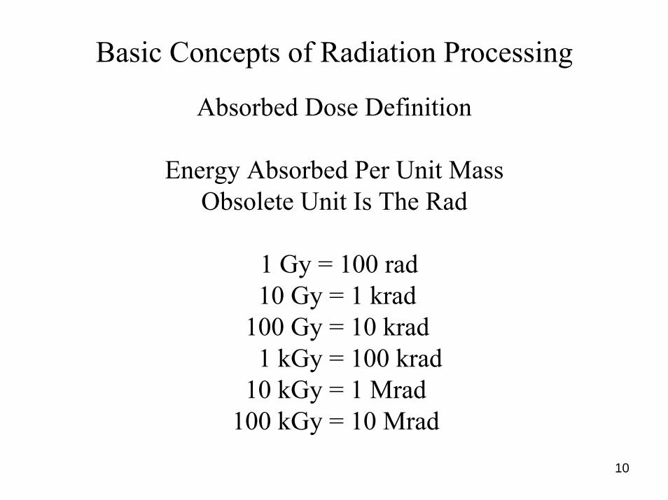
Basic Concepts of Radiation Processing
Absorbed Dose Definition
Energy Absorbed Per Unit MassObsolete Unit Is The Rad
1 Gy = 100 rad10 Gy = 1 krad
100 Gy = 10 krad1 kGy = 100 krad
10 kGy = 1 Mrad100 kGy = 10 Mrad

11
Basic Concepts of Radiation Processing
Temperature Rise vs Absorbed Dose
Temperature rise is proportional to the thermalenergy absorbed per unit mass of heated material.
Also, temperature rise is proportional to theabsorbed dose in irradiated material (in same units).
Calorimetry is the primary method for measuringabsorbed dose and calibrating secondary dosimeters.

12
Basic Concepts of Radiation Processing
Temperature Rise vs Absorbed Dose
ΔT = H / c
ΔT = D / c
ΔT = Temperature Rise in °CH = Heat per Unit Mass in J/gc = Heat Capacity in J/g °CD = Absorbed Dose in kGy

13
Basic Concepts of Radiation Processing
Examples – Temp. Rise per kGy
Material Thermal Cap. Temp. Rise
Water 4.19 0.24Polyethylene 2.30 0.43Teflon 1.05 0.95
Aluminum 0.90 1.11Iron 0.44 2.27Copper 0.38 2.63

14
Basic Concepts of Radiation ProcessingTemperature Rise for EB Processing
Industrial EB processes need less energy than mostthermal treatment processes.
Absorbed dose requirements for various industrialprocesses cover a very wide range from 0.1 kGy to1000 kGy.
Most of these processes need less than 100 kGy,many need less than 10 kGy, and some need lessthan 1 kGy.

15
Basic Concepts of Radiation Processing
Absorbed Dose Requirements
Sprout Inhibiting 0.1 – 0.2 kGyInsect Disinfesting 0.3 – 0.5 kGyParasite Control 0.3 – 0.5 kGyDelay of Ripening 0.5 – 1.0 kGyFungi Control 1.5 – 3.0 kGyBacteria Control 1.5 – 3.0 kGy

16
Basic Concepts of Radiation Processing
Absorbed Dose Requirements
Sterilizing 15 - 30 kGyPolymerizing 25 - 50 kGyGrafting 25 - 50 kGyCrosslinking 50 - 150 kGyDegrading 500 - 1500 kGyGemstone Coloring > > 1500 kGy

17
Basic Concepts of Radiation Processing
Absorbed Dose vs Molecular Weight MW and G Value
D = NA (100 / G) e / MW joules / gram
D = 9.65 x 10⁶ / (G MW) kGy
NA = 6.022 x 10²³ molecules / mole
e = 1.602 x 10⁻¹⁹ joules / electron volt
G = number of chemical reactions / 100 eV

18
Basic Concepts of Radiation Processing
Absorbed Dose vs MW and G Value
High molecular weight means acceptably low dose.
If MW = 100,000 and G = 1, then D = 100 kGy.
Low molecular weight means excessively high dose.
If MW = 100 and G = 3, then D = 32,000 kGy.

19
Basic Concepts of Radiation Processing
Absorbed Dose vs MW and G Value
Polymeric materials with high molecular weightsare good candidates for radiation processing.
Inorganic compounds with low molecular weightsare poor candidates for radiation processing.
Dilute solutions are exceptions. Ionizing a smallfraction of the solvent will affect most of the solute.
20
Applications of Radiation Processing
Modifying Polymeric MaterialsCuring Monomers and OligomersGrafting Monomers onto PolymersCrosslinking PolymersDegrading Polymers
Biological ApplicationsSterilizing Medical ProductsDisinfecting Consumer ProductsPasteurizing and Preserving Foods

21
Applications of Radiation Processing
Environmental ApplicationsReducing Acid RainTreating Waste Materials
Solid State ApplicationsModifying SemiconductorsColoring Gemstones

22
Applications of Radiation Processing
Modifying polymeric materials
Curing
Grafting
Crosslinking
Degrading

23
Applications of Radiation Processing
Curing Solvent-Free Coatings, Inks and Adhesives
OligomersAcrylated epoxiesAcrylated polyethersAcrylated urethane polyesters
Multifunctional monomersTrimethylolpropane triacrylate
Dose = 10 to 30 kGy

24
Low-Energy EB Curing of Colored Coatings
Salt Spray Resistance
Laboratory Test Panels

25
Applications of Radiation Processing
Curing Composite Materials for Spacecraft and Missiles
OligomersModified epoxies with special properties
Carbon fiber reinforcement
Dose = 150 to 250 kGy
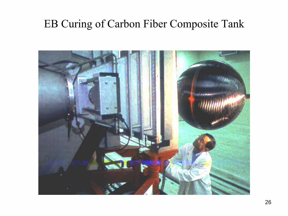
26
EB Curing of Carbon Fiber Composite Tank

27
EB Curing of Composite Missile Component

28
Applications of Radiation Processing
Materials Suitable for Grafting
A variety polymeric materialsPolyethylene, Polypropylene Polyvinyl Chloride, FluoropolymersCellulose, Wool
A variety of hydrophilic monomers
Dose = 10 kGy
29
Applications of Radiation Processing
Property Improvements by Grafting
Addition of hydrophilic surfaces on hydrophobicpolymers to make permselective membranes.
Fuel cell and battery separator films.
Improvement of surface adhesion properties.
Biocompatible materials for medical applications.

30
Applications of Radiation Processing
Typical Materials for Crosslinking
Polyethylene PolyvinylchloridePolyvinylidene fluorideEthylene-propylene rubberEthylene vinylacetatePolyacrylates
Dose = 50 to 200 kGy
31
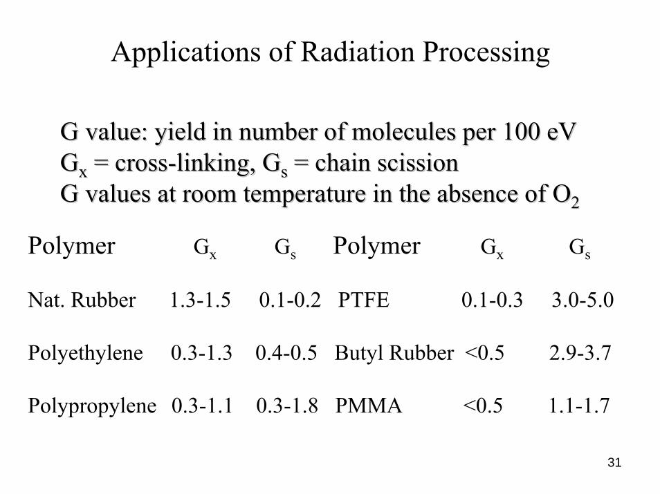
Applications of Radiation Processing
G value: yield in number of molecules per 100 G value: yield in number of molecules per 100 eVeVGGxx = cross= cross--linking, Glinking, Gss = chain scission= chain scissionG values at room temperature in the absence of OG values at room temperature in the absence of O22
Polymer Gx Gs Polymer Gx Gs
Nat. Rubber 1.3-1.5 0.1-0.2 PTFE 0.1-0.3 3.0-5.0
Polyethylene 0.3-1.3 0.4-0.5 Butyl Rubber <0.5 2.9-3.7
Polypropylene 0.3-1.1 0.3-1.8 PMMA <0.5 1.1-1.7

32
Applications of Radiation Processing
Products Improved by Crosslinking
Plastic Products in Finished FormHeat Shrinkable Tubing and FilmElectrical Wire and Cable JacketsTires for Automobiles and TrucksPlastic Foam Padding for AutomobilesBulk Plastic MaterialsHydrogel Materials

33
Crosslinking Formed Plastic Products

34
Crosslinking Heat-Shrinkable TubingPlastic Memory Effect

35
Irradiating Heat-Shrinkable Plastic Film

36
Crosslinking Electrical Wire InsulationImproved Flame Retardancy

37
Crosslinking Jackets on Multi-conductor Cables

38
Wire and Tubing Irradiation Method

39
Precuring Automobile Tire ComponentsImproved Dimensional Stability

40
Irradiating Plastic Foam Cushions for Cars

41
Applications of Radiation Processing
Degrading polymeric materials
Polytetrafluoroethylene – for powders
Polypropylene – to improve formability
Cellulose – to produce viscose for rayon

42
Degrading Scrap Polytetrafluoroethylene

43
Cellulose Degradation for Viscose and Rayon

44
Applications of Radiation Processing
Biological Applications
Sterilizing Medical Products
Disinfecting Consumer Products
Pasteurizing and Preserving Foods

45
Sterilizing Disposable Medical Products

46
Disinfecting Cosmetic Products

47
Disinfesting Fresh Fruits and Vegetables

48
Pasteurizing Uncooked Meats

49
Pasteurizing Natural Spices

50
Applications of Radiation Processing
Environmental Applications
Reducing Acid Rain – by extractingsulfur and nitrogen oxides from smoke
Treating Waste Materials – by decomposingtoxic substances from wastewater

51
Pomorzany Flue Gas EB Process Flow Diagram

52
Pomorzany Flue Gas EB Irradiation Vessel
53
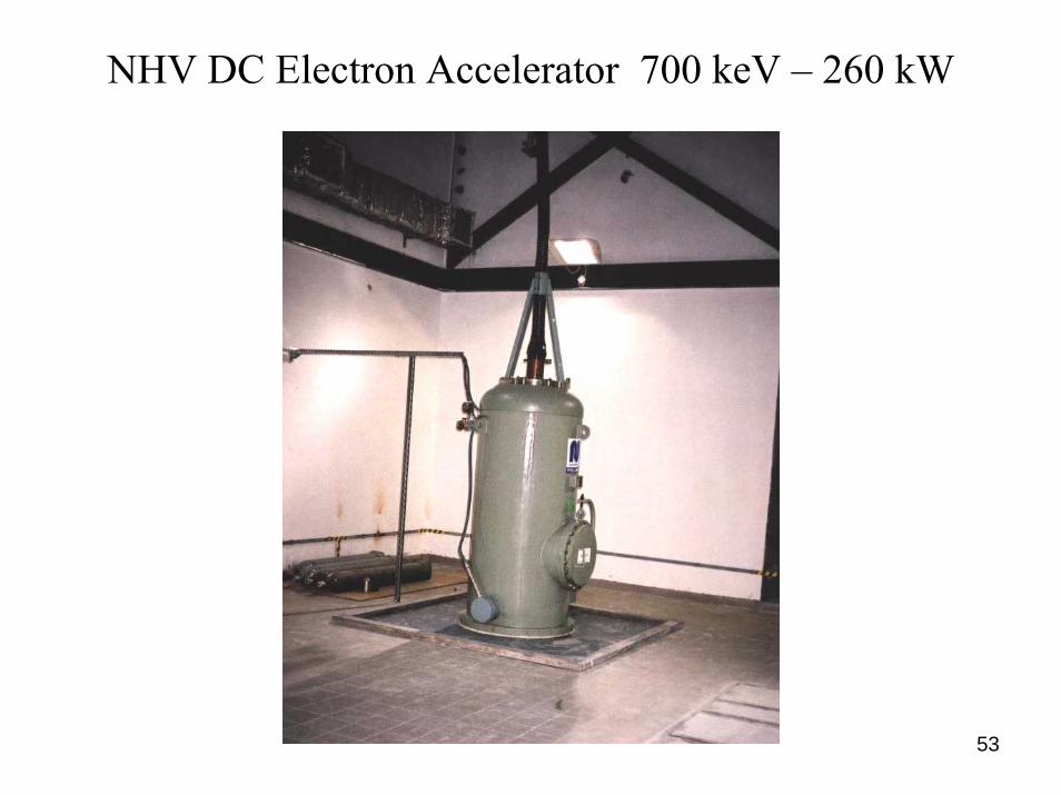
NHV DC Electron Accelerator 700 keV – 260 kW

54
Wastewater Treatment Plant

55
Miami Dade County EB Wastewater Treatment

56
Miami Dade County EB Wastewater Treatment

57
Applications of Radiation Processing
Solid State Applications
Modifying Semiconductors
Coloring Gemstones

58
Modifying Semiconductors

59
Modifying Semiconductors

60
Coloring Gemstones

61
Physical Aspects of Radiation Processing
Material Penetration vs Electron Energy
Mass Throughput Rate vs Electron Beam Power
Area Throughput Rate vs Electron Beam Current
X-Ray Processing Characteristics

62
Physical Aspects of Radiation Processing
0.0
0.5
1.0
1.5
2.0
2.5
3.0
0.0 0.5 1.0 1.5 2.0 2.5 3.0 3.5
Thickness x Density ( g / sq cm )
Elec
tron
Ener
gy D
epos
ition
( MeV
sq
cm /
g )
PEPSPVCPTFE
Penetration Penetration vsvs Electron EnergyElectron EnergyPolymer Comparisons Polymer Comparisons –– 5 MeV5 MeV

63
Physical Aspects of Radiation ProcessingPenetration vs Electron Energy
Polymer Comparisons
Hydrogen has more atomic electrons per unit massthan any other element.
Polymers with more hydrogen have higher energydepositions per incident electron.
Polymers with more hydrogen have lower electronranges for the same incident electron energy.

64
Physical Aspects of Radiation Processing
0.0
1.0
2.0
3.0
4.0
5.0
6.0
0.00 0.05 0.10 0.15 0.20 0.25 0.30 0.35
Thickness x Density ( g / sq cm )
Elec
tron
Ener
gy D
epos
ition
( M
eV sq
cm
/ g
) 0.4 MeV0.6 MeV0.8 MeV0.8 Charge
Penetration Penetration vsvs Electron EnergyElectron EnergyPolyethylenePolyethylene

65
Physical Aspects of Radiation Processing
0.0
1.0
2.0
3.0
4.0
0.00 0.25 0.50 0.75 1.00 1.25 1.50 1.75
Thickness x Density ( g / sq cm )
Elec
tron
Ener
gy
Dep
ositi
on( M
eV sq
cm
/ g
)
1.0 MeV1.5 MeV2.0 MeV3.0 MeV3.0 Charge
Penetration Penetration vsvs Electron EnergyElectron EnergyPolyethylenePolyethylene

66
Physical Aspects of Radiation Processing
0.0
0.5
1.0
1.5
2.0
2.5
3.0
0.0 1.0 2.0 3.0 4.0 5.0 6.0
Thickness x Density ( g / sq cm )
Elec
tron
Ener
gy D
epos
ition
( MeV
sq c
m /
g )
5.0 MeV7.5 MeV10 MeV10 Charge
Penetration Penetration vsvs Electron EnergyElectron EnergyPolyethylenePolyethylene

67
Physical Aspects of Radiation Processing
Penetration vs Electron EnergyElectrostatic Charge Deposition
Electrostatic charges are deposited by incidentelectrons which come to rest in thick materials.
The charge depositions are concentrated near theEnds of the electron ranges.
The charge density decreases and the total energydeposition increases as the incident electron energyincreases.

68
Physical Aspects of Radiation Processing
Electron Range DefinitionsElectron Range Definitions

69
Physical Aspects of Radiation Processing
Electron Range DefinitionsElectron Range Definitions
R(opt) ─ Exit Dose Equals Entrance Dose
R(50) ─ Exit Dose Equals Half Maximum Dose
R(50e) ─ Exit Dose Equals Half Entrance Dose
R(p) ─ Tangent Line Extends to Zero Dose

70
Physical Aspects of Radiation ProcessingElectron Range Values
MeV R(opt) R(50) R(50e) R(p)0.4 0.000 0.054 0.054 0.0830.6 0.075 0.126 0.129 0.1690.8 0.161 0.202 0.214 0.2621.0 0.243 0.282 0.302 0.3581.5 0.449 0.486 0.529 0.6102.0 0.652 0.699 0.754 0.8613.0 1.054 1.128 1.209 1.3735.0 1.859 2.000 2.131 2.4057.5 2.854 3.134 3.284 3.682
10.0 3.884 4.204 4.429 4.955
71
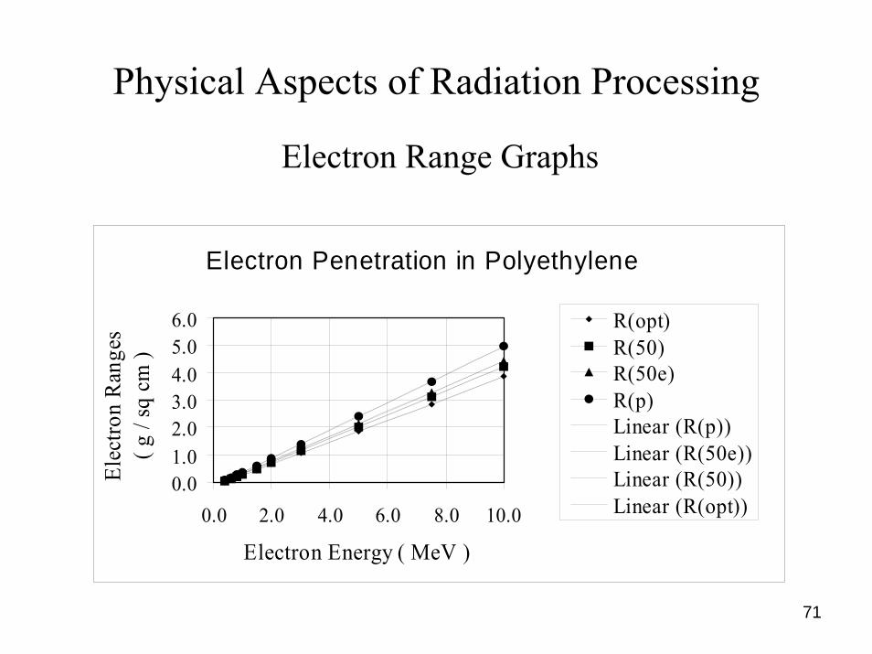
Physical Aspects of Radiation Processing
Electron Penetration in Polyethylene
0.01.02.03.04.05.06.0
0.0 2.0 4.0 6.0 8.0 10.0
Electron Energy ( MeV )
Elec
tron
Ran
ges
( g /
sq c
m )
R(opt)R(50)R(50e)R(p)Linear (R(p))Linear (R(50e))Linear (R(50))Linear (R(opt))
Electron Range Graphs
72
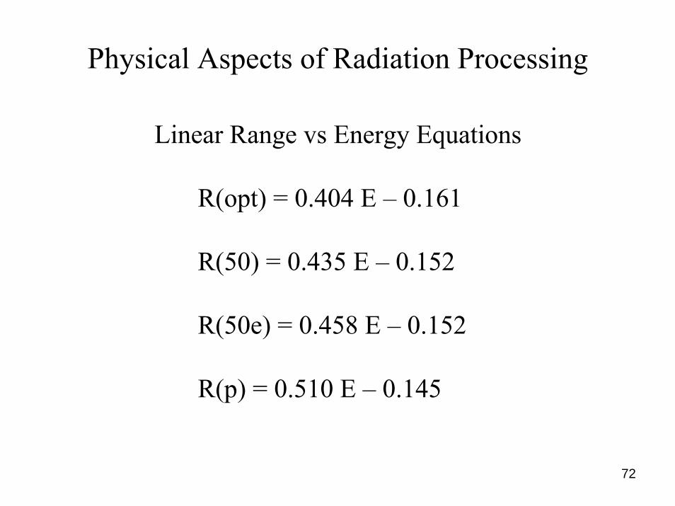
Physical Aspects of Radiation Processing
Linear Range vs Energy Equations
R(opt) = 0.404 E – 0.161
R(50) = 0.435 E – 0.152
R(50e) = 0.458 E – 0.152
R(p) = 0.510 E – 0.145

73
Physical Aspects of Radiation Processing
Electron ranges in other materials can be estimated by multiplying the polyethylene range with the ratio of their CSDA ranges.
R(material) = R(polyethylene) x CSDA(m) / CSDA(pe)
CSDA ranges for many materials with a wide range ofelectron energies can be obtained from ICRU Report 37.
Ranges in Other Materials

74
Physical Aspects of Radiation Processing
Absorbed Dose vs Electron Beam Power
1 kGy = 1 kJ/kg
D(ave) = F(p) P T / M
D(ave) = F(p) P / (M / T)
D(ave) = average dose in kGyP = emitted power in kWT = treatment time in s
M = mass in kg

75
Physical Aspects of Radiation Processing
Mass Throughput Rate vs Electron Beam Power
M / T = F(p) P / D(ave)
F(p) = F(e) F(i)
F(p) = fraction of emitted power absorbedF(e) = fraction of incident power absorbedF(i) = fraction of emitted current intercepted

76
Physical Aspects of Radiation Processing
Mass Throughput Rate vs Electron Beam Power
M / T = f(p) P / D(o)
f(p) = f(e) F(i)
D(o) = surface dose in kGyf(p) = surface dose value of F(p)f(e) = surface dose value of F(e)

77
Physical Aspects of Radiation Processing

78
Physical Aspects of Radiation ProcessingProcessing Parameters vs Incident Energy
MeV D(e) K(o) f(e) F(e)0.4 4.963 0.496 0.000 0.0000.6 3.795 0.380 0.474 0.4960.8 2.982 0.298 0.599 0.6951.0 2.550 0.255 0.619 0.7771.5 2.118 0.212 0.634 0.8502.0 1.966 0.197 0.641 0.8623.0 1.887 0.189 0.663 0.8675.0 1.860 0.186 0.692 0.8757.5 1.860 0.186 0.708 0.873
10.0 1.878 0.188 0.730 0.867

79
Physical Aspects of Radiation Processing
Example – Mass Throughput Rate
E = 1.0 MeVP = 100 kW
F(i) = 0.80f(e) = 0.619
D(o) = 100 kGy
M / T = 0.619 x 0.80 x 100 / 100
M / T = 0.495 kg/s or 1783 kg/h

80
Physical Aspects of Radiation Processing
Absorbed Dose vs Electron Beam Current
D (kGy) = P (kW) T (s) / M (kg)
P (kW) = E (MeV) I (mA)
E (MeV) = D(e) (MeV cm2/g) Z (g/cm2)
D(e) = energy deposition per electronZ = thickness x density (g/cm2)Z = mass / area (g/cm2)

81
Physical Aspects of Radiation Processing
Absorbed Dose vs Electron Beam Current
D (kGy) = E (MeV) I (mA) T (s) / M (kg)
D (kGy) = D(e) Z I (mA) T (s) / M (kg)
D (kGy) = D(e) Z I (mA) T (s) / Z A (cm2) 10-3
D (kGy) = D(e) I (mA) T (s) / 10 A (m2)

82
Physical Aspects of Radiation Processing
Absorbed Dose vs Electron Beam Current
D(z) = K(z) F(i) I T / A
D(z) = dose at the depth z in kGyK(z) = D(e, z) / 10 in kGy m2/mA sK(z) = Area Processing Coefficient ─ evaluated
at the depth where the dose is specifiedF(i) = fraction of emitted beam current intercepted
I = emitted beam current in mAT = treatment time in s
A = product area in m2

83
Physical Aspects of Radiation Processing
Area Throughput Rate vs Electron Beam Current
A / T = K(z) F(i) I / D(z)
A / T = area throughput rate in m2/sK = D(e) / 10 in kGy m2/mA sK = Area Processing Coefficient
F(i) = fraction of beam current interceptedF(i) = product area / irradiated area
I = emitted beam current in mAD(z) = dose in kGy where K(z) is evaluated

84
Physical Aspects of Radiation ProcessingProcessing Parameters vs Incident Energy
MeV D(e) K(o) f(e) F(e)0.4 4.963 0.496 0.000 0.0000.6 3.795 0.380 0.474 0.4960.8 2.982 0.298 0.599 0.6951.0 2.550 0.255 0.619 0.7771.5 2.118 0.212 0.634 0.8502.0 1.966 0.197 0.641 0.8623.0 1.887 0.189 0.663 0.8675.0 1.860 0.186 0.692 0.8757.5 1.860 0.186 0.708 0.873
10.0 1.878 0.188 0.730 0.867

85
Physical Aspects of Radiation Processing
Example – Area Throughput Rate
E = 1.0 MeVI = 100 mA
F(i) = 0.80K(o) = 0.255D(o) = 100 kGy
A / T = 0.255 x 0.80 x 100 / 100
A / T = 0.204 m2/s or 734 m2/h

86
Physical Aspects of Radiation Processing
Example – Mass Throughput from Area Throughput
E = 1.0 MeVI = 100 mA
F(i) = 0.80R(opt) = 0.243 g/cm2 or 2.43 kg/m2
A / T = 734 m2/h
M / T = (A / T) x R(opt)
M / T = 734 x 2.43 = 1785 kg/h

87
Physical Aspects of Radiation Processing
X-Ray Processing Characteristics
X-Ray Energy and Angular Distributions
X-Ray Broad Beam Penetration in Water
X-Ray Utilization vs Product Thickness
X-Ray Emission Efficiency vs Electron Energy
PalletronTM Rotational X-Ray Processing

88
X-Ray Photon Energy Spectrum

89
X-Ray Photon Angular Distribution
0 30 60 90Polar Angle (deg)
0
4
8
12
Phot
on In
tens
ity (r
el. u
nits
)10 MeV7.5 MeV5 MeV

Broad Beam X-Ray Penetration in Water
0 10 20 30 40Depth (cm)
Dos
e (r
el. u
nits
)
10 MeV7.5 MeV5 MeV
EnergyTenth Value Layer (cm)Present Work prev.
(MeV) Calc. Exp. Calc.10 49.0 47.9 49.07.5 44.3 N/A N/A5 39.0 39.5 38.0

Two-Sided X-Ray Process in Water
Optimum ThicknessEnergy 2/λ(MeV) (cm)
10 42.57.5 38.55 33.9
0 10 20 30 40 50 60 70Treated Thickness (g/cm²)
1
1.5
2
2.5
3
3.5
4
Dm
ax/D
min
Phot
on P
ower
Util
izat
ion
(rel
. uni
ts)
10 MeV7.5 MeV5 MeV

92
Two-Sided X-Rays vs Gamma Rays
Electron X-Ray Tenth Value Layer Optimum ThicknessEnergy Efficiency Calculation Double Sided(MeV) (%) (cm water) (cm) Max/Min
10.0 16.2 49.0 43 1.54
7.5 13.3 44.3 38 1.54
5.0 8.2 39.0 34 1.54
Co-60 31.0 28 1.75

93
Two-Sided X-Ray Irradiation

94
Sterigenics Dual-Beam X-ray Facility

95
IBA PalletronTM Rotational Method
Accelerator X-ray Target Collimator Pallet Turntable
Control System

96
IBA PalletronTM Rotational Method

97
IBA Palletron® Dose Distribution Measurement Verification of Monte Carlo Simulation

98
ALLETRON ROTATIONAL METHOD
A/D << 1
A/D = 1
⇒ Optimal A/D = 0.55DUR versus A/D
D= 80 cm / ρ= 0.8
IBA PalletronTM Rotational Method
Cylinder Irradiation with X-Rays

99
r £ 0.4:– constant rotation speed– collimators widely open
r > 0.4:– variable rotation speed– aperture tuned to product
densitySignificant gain at 7.5 MeV:
– Better conversion efficiency– More energetic X-Rays– X-rays peaked forward
IBA PalletronTM Performance Figures
100
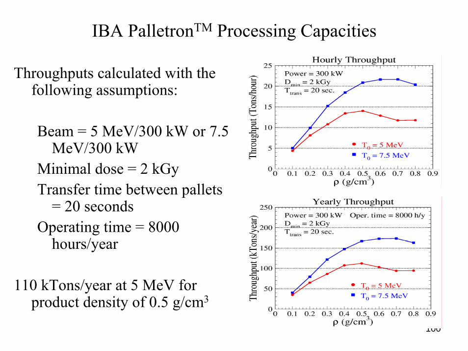
IBA PalletronTM Processing Capacities
Throughputs calculated with thefollowing assumptions:
Beam = 5 MeV/300 kW or 7.5 MeV/300 kW
Minimal dose = 2 kGyTransfer time between pallets
= 20 secondsOperating time = 8000
hours/year
110 kTons/year at 5 MeV for product density of 0.5 g/cm3

101
Industrial Electron Accelerators
Direct Current AcceleratorsSingle Gap – Extended BeamMultiple Gap – Scanned Beam
Microwave Linear AcceleratorsS-Band SystemsL-Band Systems
Radio Frequency AcceleratorsSingle Cavity – Single PassSingle Cavity – Multiple Pass

102
Industrial Electron Accelerators
Direct Current Accelerators
Single Gap – Extended Beam
Electron Energy – 80 keV to 300 keVElectron Beam Power – up to 300 kWElectron Beam Width – up to 3 m

103
RPC BroadBeam® Electron Beam Processor

104
AEB Modular EB Emitter 120 keV - 40 mA

105
AEB Modular Two-Emitter Assembly

106
Industrial Electron Accelerators
Direct Current Accelerators
Multiple Gap – Scanned Beam
Electron Energy – 300 keV to 5 MeVElectron Beam Power – up to 300 kWElectron Beam Width – up to 3 m

107
Industrial Electron Accelerators
Multiple Gap – Scanned Beam DC Accelerator

108
Industrial Electron Accelerators
Parallel-Coupled Capacitive Cascade Circuit

109
Industrial Electron Accelerators
Parallel-Coupled Capacitive Cascade Circuit

RDI Dynamitron® Assembly Drawing
Scan Horn
Beam Window
Heat Exchanger
Electron Gun
Rectifier Modules Acceleration Tube
RF Transformer
Vacuum Pump
RF Electrodes

111
RDI Dynamitron® Assembly 5 MeV – 300 kW

112
RDI Dynamitron® Rectifier Column 5 MeV

113
RDI Dynamitron® EB Processing Facility

114
Industrial Electron Accelerators
Microwave Linear Accelerators
S-Band Systems
Microwave Frequency – 3 GHzElectron Energy – 2 MeV to 20 MeVElectron Beam Power – up to 20 kWElectron Beam Width – up to 1 m

115
SureBeam Dual S-Band Linac EB Facility
116
Industrial Electron Accelerators
Microwave Linear Accelerators
L-Band Systems
Microwave Frequency – 1.3 GHzElectron Energy – 5 MeV to 10 MeVElectron Beam Power – up to 80 kWElectron Beam Width – up to 1.5 m

117
SureBeam L-Band Linac 5 MeV – 80 kW

118
SureBeam Dual L-Band Linac X-Ray Facility

119
AECL Impela® L-Band Linac 10 MeV – 60 kW

120
Iotron Impela® L-Band Linac EB Facility

121
Industrial Electron Accelerators
Radio Frequency Accelerators
Single Cavity – Single Pass Systems
Radio Frequency – 100 to 200 MHzElectron Energy – 0.5 MeV to 4 MeVElectron Beam Power – up to 50 kWElectron Beam Width – up to 1 m

122
Industrial Electron Accelerators
Radio Frequency Accelerators
Single Cavity – Multiple Pass Systems
Radio Frequency – 107 to 215 MHzElectron Energy – 5 MeV to 10 MeVElectron Beam Power – up to 700 kWElectron Beam Width – up to 2 m

Operating Principle (1)
E
G
DD
E
IBA Rhodotron® RF Electron Accelerator
Inward Acceleration

Operating Principle (2)
G
DD
IBA Rhodotron® RF Electron Accelerator
RF Field Reversal

Operating Principle (3)
G
DD
E
E
IBA Rhodotron® RF Electron Accelerator
Outward Acceleration

Operating Principle (4)
G
D
E
E
IBA Rhodotron® RF Electron Accelerator
Beam Deflection
RF Field Reversal
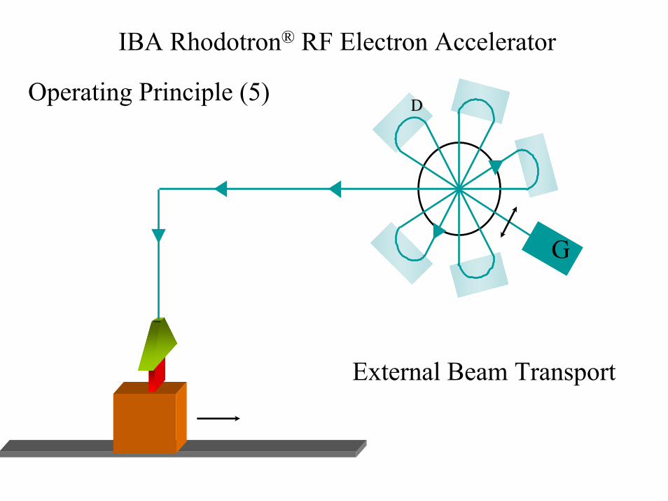
Operating Principle (5)
G
DD
IBA Rhodotron® RF Electron Accelerator
External Beam Transport

E B
Electric (E) and magnetic (B) fields in a Rhodotron coaxial cavity
IBA Rhodotron® RF Electron Accelerator

129
IBA Rhodotron® RF Electron AcceleratorCopper Plated Steel Cavity

130
IBA Rhodotron® RF Electron AcceleratorAssembly of Beam Reversing Magnets

131
IBA Rhodotron® RF Electron AcceleratorModel TT1000 7 MeV – 100 mA – 700 kW
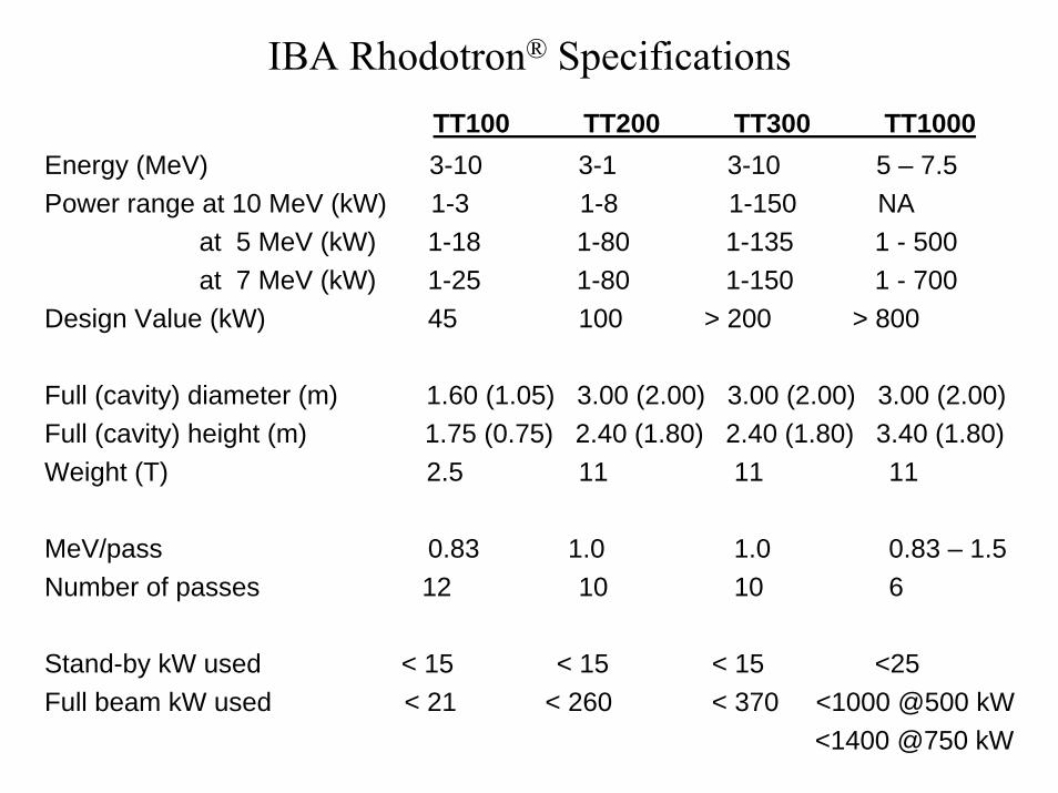
TT100 TT200 TT300 TT1000Energy (MeV) 3-10 3-1 3-10 5 – 7.5Power range at 10 MeV (kW) 1-3 1-8 1-150 NA
at 5 MeV (kW) 1-18 1-80 1-135 1 - 500at 7 MeV (kW) 1-25 1-80 1-150 1 - 700
Design Value (kW) 45 100 > 200 > 800
Full (cavity) diameter (m) 1.60 (1.05) 3.00 (2.00) 3.00 (2.00) 3.00 (2.00) Full (cavity) height (m) 1.75 (0.75) 2.40 (1.80) 2.40 (1.80) 3.40 (1.80)Weight (T) 2.5 11 11 11
MeV/pass 0.83 1.0 1.0 0.83 – 1.5Number of passes 12 10 10 6
Stand-by kW used < 15 < 15 < 15 <25Full beam kW used < 21 < 260 < 370 <1000 @500 kW
<1400 @750 kW
IBA Rhodotron® Specifications

133
IBA Rhodotron EB Processing Facility

134
Industrial Applications of Electron Accelerators
Conclusion
Ideas about how to accelerate atomic particles to highenergies originated about 75 years ago. The motivation then was to investigate the structure of atomic nuclei.
Those early concepts have evolved into very complexaccelerator technologies, which have many practicalapplications outside the field of nuclear physics.

135
Industrial Applications of Electron Accelerators
Conclusion
Radiation processing of materials and commercialproducts is one of those offshoots. It is a diverse fieldthat has justified constructing over 1000 industrialelectron beam irradiation facilities.
Some of the emerging applications, such as foodirradiation and reduction of environmental pollution,offer the prospects of significant benefits to humanhealth and wellfare.