inductance - wake forest student, faculty and...
TRANSCRIPT
InductanceSelf-InductanceRL CircuitsEnergy in a Magnetic FieldMutual InductanceOscillations in an LC Circuit
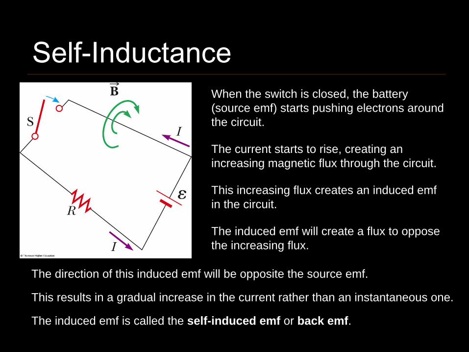
Self-InductanceWhen the switch is closed, the battery (source emf) starts pushing electrons around the circuit.
The current starts to rise, creating an increasing magnetic flux through the circuit.
This increasing flux creates an induced emf in the circuit.
The induced emf will create a flux to oppose the increasing flux.
The direction of this induced emf will be opposite the source emf.
This results in a gradual increase in the current rather than an instantaneous one.
The induced emf is called the self-induced emf or back emf.
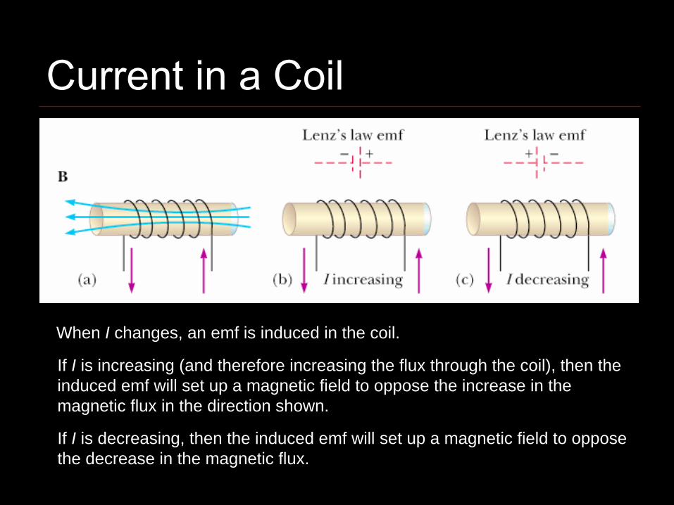
When I changes, an emf is induced in the coil.
If I is increasing (and therefore increasing the flux through the coil), then the induced emf will set up a magnetic field to oppose the increase in the magnetic flux in the direction shown.
If I is decreasing, then the induced emf will set up a magnetic field to oppose the decrease in the magnetic flux.
Current in a Coil
Self-Inductance
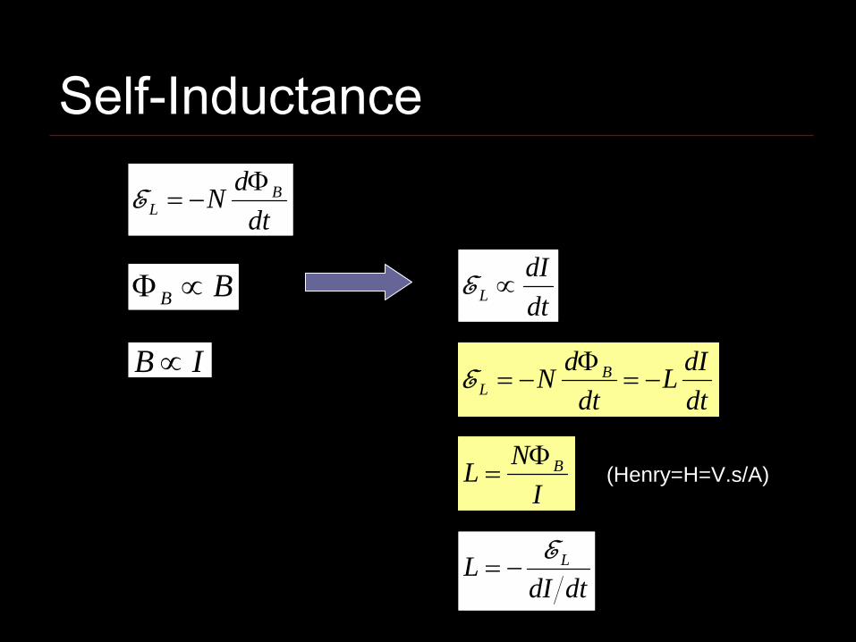
dtdN B
LΦ
−=E
BB ∝Φ
IB ∝
dtdI
L ∝E
dtdIL
dtdN B
L −=Φ
−=E
INL BΦ
=
dtdIL LE−=
(Henry=H=V.s/A)
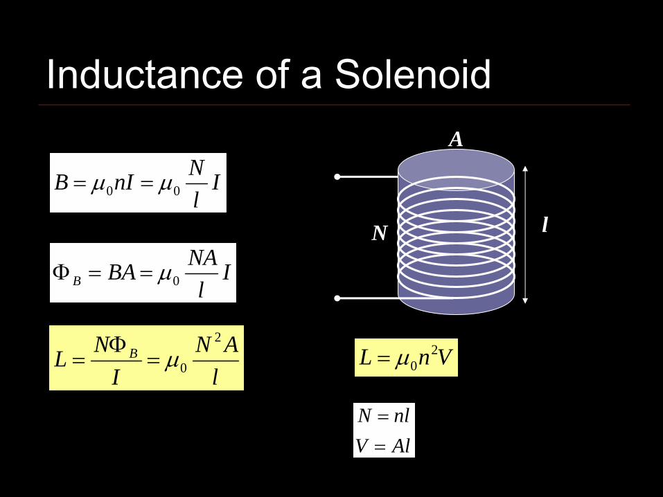
Inductance of a Solenoid
IlNnIB 00 μμ ==
Il
NABAB 0μ==Φ
lAN
INL B
2
0μ=Φ
= VnL 20μ=
AlVnlN
==
lN
A
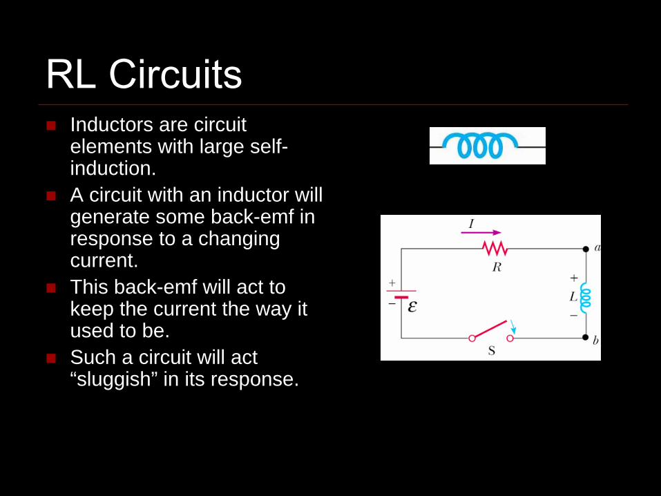
RL CircuitsInductors are circuit elements with large self-induction.A circuit with an inductor will generate some back-emf in response to a changing current.This back-emf will act to keep the current the way it used to be.Such a circuit will act “sluggish” in its response.

RL Circuit Analysis
dtdILL −=E
0=−−dtdILIRE
( )τ/1 teR
I −−=E
RL
=τ
When S2 is at a
0=+dtdILIR
τ/tieII −=
RL
=τ
When S2 is at b
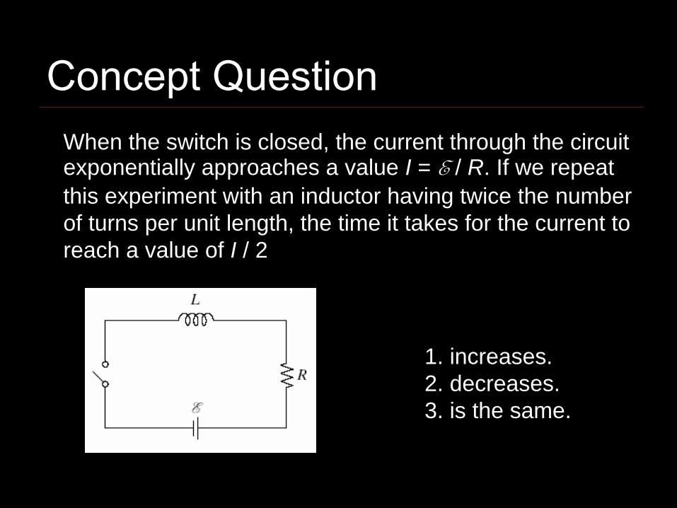
When the switch is closed, the current through the circuit exponentially approaches a value I = E / R. If we repeat this experiment with an inductor having twice the number of turns per unit length, the time it takes for the current to reach a value of I / 2
1. increases.2. decreases.3. is the same.
Concept Question
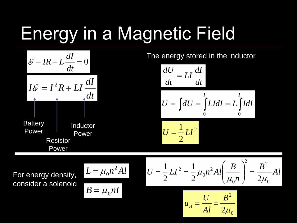
Energy in a Magnetic Field
dtdILIRII += 2E
0=−−dtdILIRE
Battery Power
Resistor Power
Inductor Power
The energy stored in the inductor
dtdILI
dtdU
=
∫∫∫ ===II
IdILLIdIdUU00
2
21 LIU =
For energy density, consider a solenoid
AlnL 20μ=
nIB 0μ=
AlBn
BAlnLIU0
22
0
20
2
221
21
μμμ =⎟⎟
⎠
⎞⎜⎜⎝
⎛==
0
2
2μB
AlUuB ==

Inductance of a Coaxial Cable∫=Φ BdAB
⎟⎠⎞
⎜⎝⎛====Φ ∫∫∫ a
bIlrdrIlldr
rIBdA
b
a
b
aB ln
222000
πμ
πμ
πμ
ldrdA =
⎟⎠⎞
⎜⎝⎛=
Φ=
abl
IL B ln
20
πμ
2
21 LIU =
⎟⎠⎞
⎜⎝⎛=
ablIU ln
4
20
πμ
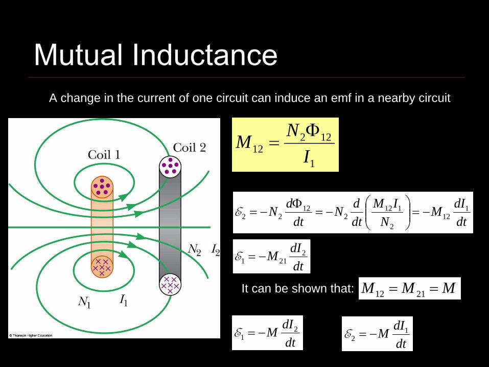
Mutual InductanceA change in the current of one circuit can induce an emf in a nearby circuit
1
12212 I
NM Φ=
dtdIM
NIM
dtdN
dtdN 1
122
1122
1222 −=⎟⎟
⎠
⎞⎜⎜⎝
⎛−=
Φ−=E
dtdIM 2
211 −=E
It can be shown that: MMM == 2112
dtdIM 2
1 −=EdtdIM 1
2 −=E
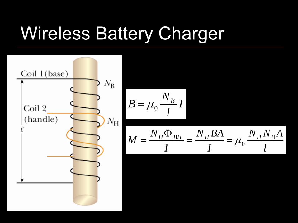
Wireless Battery Charger
Il
NB B0μ=
lANN
IBAN
INM BHHBHH
0μ==Φ
=
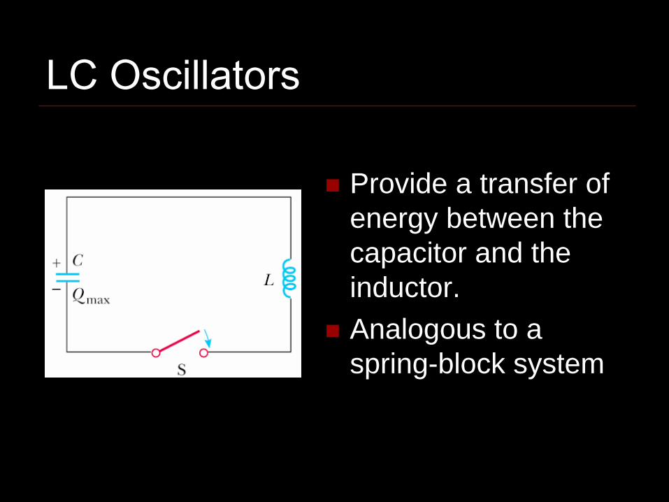
LC Oscillators
Provide a transfer of energy between the capacitor and the inductor.Analogous to a spring-block system

Assume the capacitor is fully charged and thus has some stored energy.
When the switch is closed, the charges on the capacitor leave the plates and move in the circuit, setting up a current.
The Oscillation Cycle
This current starts to discharge the capacitor and reduce its stored energy.

The Oscillation Cycle
When the capacitor is fully discharged, it stores no energy, but the current reaches a maximum and all the energy is stored in the inductor.
At the same time, the current increases the stored energy in the magnetic field of the inductor.
The Oscillation Cycle
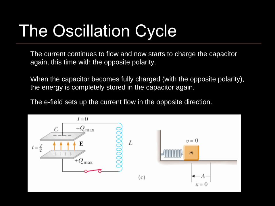
When the capacitor becomes fully charged (with the opposite polarity), the energy is completely stored in the capacitor again.
The e-field sets up the current flow in the opposite direction.
The current continues to flow and now starts to charge the capacitor again, this time with the opposite polarity.
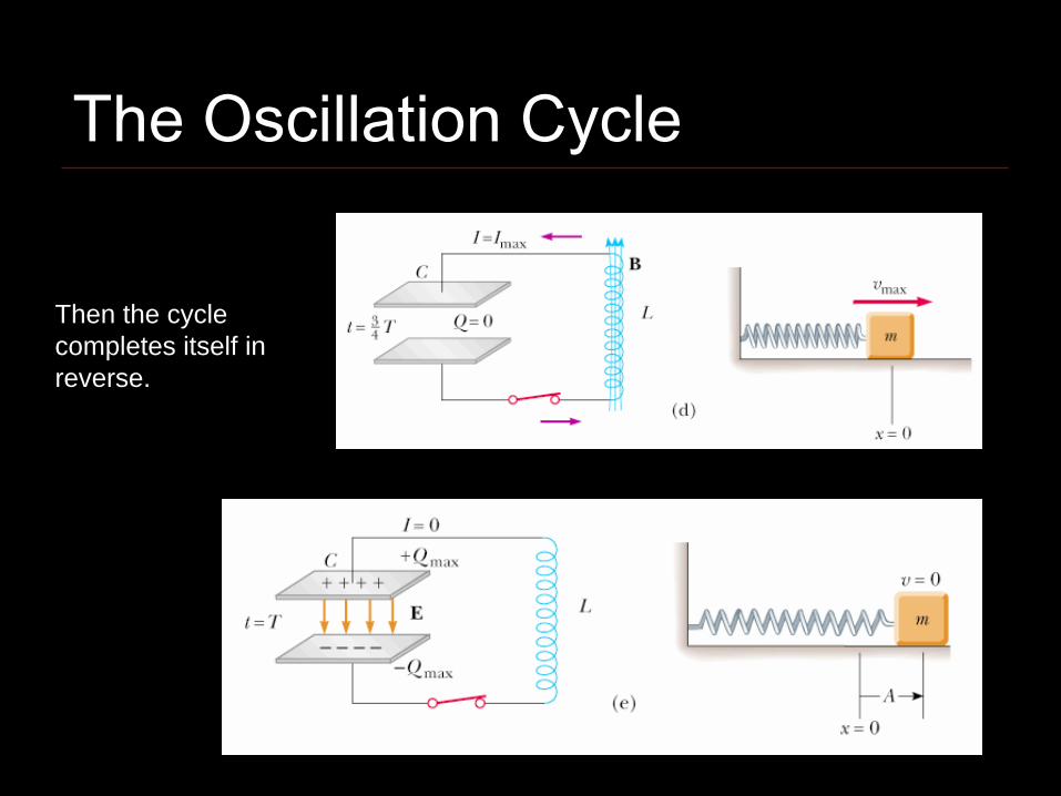
Then the cycle completes itself in reverse.
The Oscillation Cycle
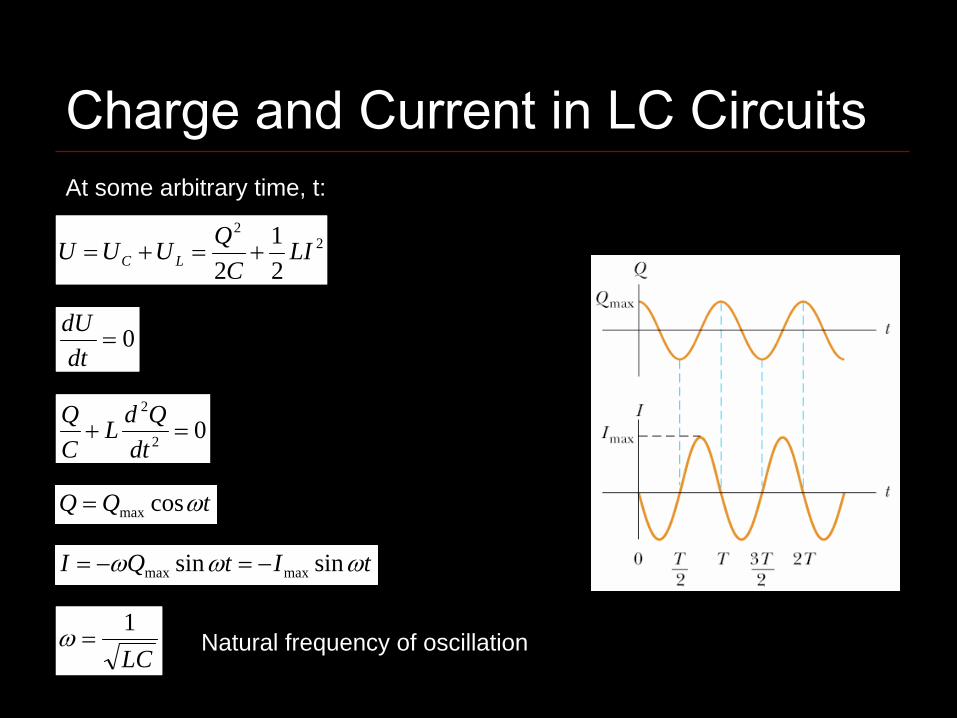
Charge and Current in LC CircuitsAt some arbitrary time, t:
22
21
2LI
CQUUU LC +=+=
0=dtdU
02
2
=+dt
QdLCQ
LC1
=ω Natural frequency of oscillation
tQQ ωcosmax=
tItQI ωωω sinsin maxmax −=−=
tLItC
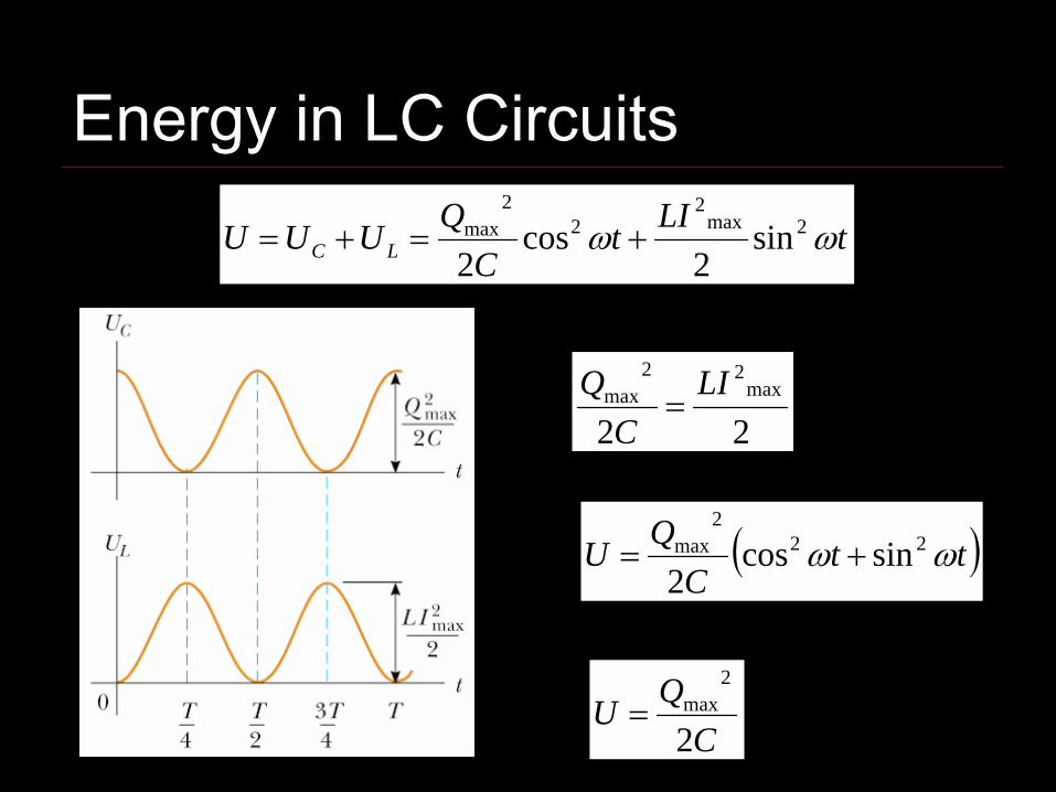
QUUU LC ωω 2max2
22
max sin2
cos2
+=+=
22max
22max LIC
Q=
( )ttC
QU ωω 222
max sincos2
+=
CQU2
2max=
Energy in LC Circuits
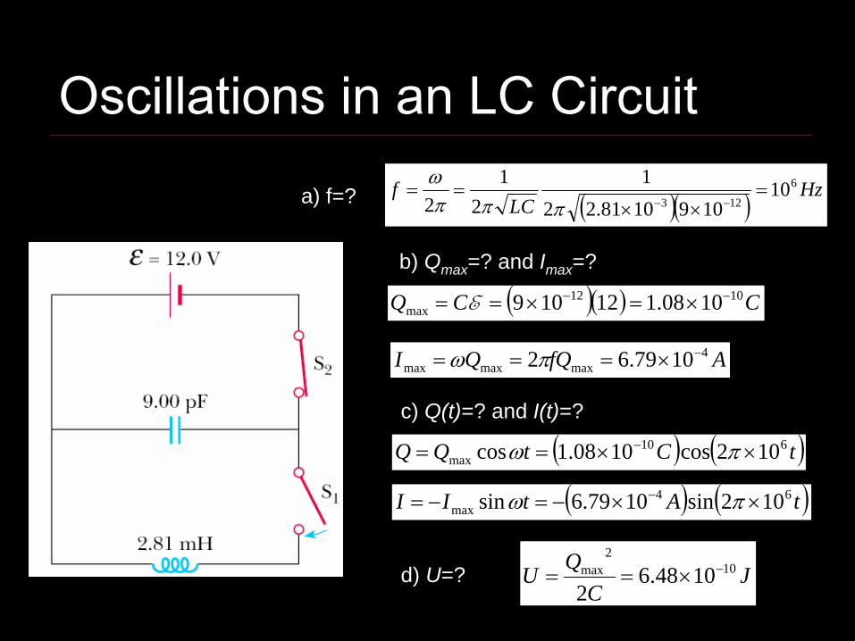
a) f=? ( )( ) HzLC
f 6
12310
1091081.221
21
2=
××==
−−πππω
b) Qmax =? and Imax =?
( )( ) CCQ 1012max 1008.112109 −− ×=×== E
AfQQI 4maxmaxmax 1079.62 −×=== πω
c) Q(t)=? and I(t)=?
( ) ( )tCtQQ 610max 102cos1008.1cos ××== − πω
( ) ( )tAtII 64max 102sin1079.6sin ××−=−= − πω
d) U=? JC
QU 102
max 1048.62
−×==
Oscillations in an LC Circuit

RLC Circuits –
Damped Oscillations
RLC Circuit - A more realistic circuitThe resistor represents the losses in the system.Can be oscillatory, but the amplitude decreases.
212
2max
21
cos
⎥⎥⎦
⎤
⎢⎢⎣
⎡⎟⎠⎞
⎜⎝⎛−=
= −
LR
LC
teQQ
d
dLRt
ω
ω
CLR 4<
For Next ClassReading Assignment
Chapter 33 - Alternating Current Circuits
WebAssign: Assignment 10