indoor mapping exercise plotting information from seismic profiles on to a map
TRANSCRIPT

Indoor mapping exercise
Plotting information from seismic profiles on to a map

Seismic profiles are 2D images of the subsurface but the view they give can be compared to a rock outcrop such as a cliff
exposure in the field, only on a much bigger scale.
This exercise plots information from seismic profiles on to a map and is good practice for field mapping and visualizing structures in
3D.

Steps 1-4

0.200
0.300
0.400
0.500
0.600
0.700
0.800
0.900
1.000
1.100
1.200
1.300
1.400
0.200
0.300
0.400
0.500
0.600
0.700
0.800
0.900
1.000
1.100
1.200
1.300
1.400
760.0780.0800.0820.0840.0860.0880.0900.0920.0940.0960.0980.01000.01020.01040.01060.01080.01100.01120.01140.01160.01180.01200.01220.01240.01260.01280.01300.01320.01340.01360.0- B92-40 -
1380.01400.01420.01440.01460.01480.01500.01520.01540.01560.01580.01600.01620.01640.01660.01680.01700.01720.01740.01760.01780.0SP:
0.200
0.300
0.400
0.500
0.600
0.700
0.800
0.900
1.000
1.100
1.200
1.300
1.400
BP-84-195, 1330.85B90-37, 399.04
N
800 900 1000 1100 1200 1300 1400 1500 1600
600
800
1000
1200
400
200
0
TWT
(mse
c)
TWT (m
sec)
CMP
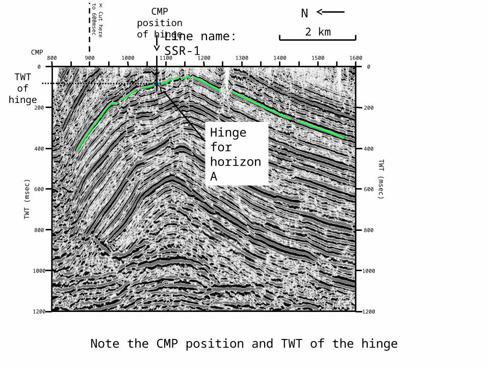
2 kmLine name: SSR-1
✂
Cut here
to 600msec
0
600
800
1000
1200
400
200
Mark the position of the hinge
1. Trace the line of each limb to see where they meet.
2. Measure the interlimb angle and mark the centre point.
Hinge for horizon A
3. The intersection of half the interlimb angle and the horizon is the hinge.
⁾∥ ⁾∥
0.200
0.300
0.400
0.500
0.600
0.700
0.800
0.900
1.000
1.100
1.200
1.300
1.400
0.200
0.300
0.400
0.500
0.600
0.700
0.800
0.900
1.000
1.100
1.200
1.300
1.400
760.0780.0800.0820.0840.0860.0880.0900.0920.0940.0960.0980.01000.01020.01040.01060.01080.01100.01120.01140.01160.01180.01200.01220.01240.01260.01280.01300.01320.01340.01360.0- B92-40 -
1380.01400.01420.01440.01460.01480.01500.01520.01540.01560.01580.01600.01620.01640.01660.01680.01700.01720.01740.01760.01780.0SP:
0.200
0.300
0.400
0.500
0.600
0.700
0.800
0.900
1.000
1.100
1.200
1.300
1.400
BP-84-195, 1330.85B90-37, 399.04
N
800 900 1000 1100 1200 1300 1400 1500 1600
600
800
1000
1200
400
200
0
TWT
(mse
c)
TWT (m
sec)
CMP
2 kmLine name: SSR-1
✂
Cut here
to 600msec
0
600
800
1000
1200
400
200
Note the CMP position and TWT of the hinge
Hinge for horizon A
CMP positionof hinge
TWTof hinge

0.200
0.300
0.400
0.500
0.600
0.700
0.800
0.900
1.000
1.100
1.200
1.300
1.400
0.200
0.300
0.400
0.500
0.600
0.700
0.800
0.900
1.000
1.100
1.200
1.300
1.400
760.0780.0800.0820.0840.0860.0880.0900.0920.0940.0960.0980.01000.01020.01040.01060.01080.01100.01120.01140.01160.01180.01200.01220.01240.01260.01280.01300.01320.01340.01360.0- B92-40 -
1380.01400.01420.01440.01460.01480.01500.01520.01540.01560.01580.01600.01620.01640.01660.01680.01700.01720.01740.01760.01780.0SP:
0.200
0.300
0.400
0.500
0.600
0.700
0.800
0.900
1.000
1.100
1.200
1.300
1.400
BP-84-195, 1330.85B90-37, 399.04
N
800 900 1000 1100 1200 1300 1400 1500 1600
600
800
1000
1200
400
200
0
TWT
(mse
c)
TWT (m
sec)
CMP
2 kmLine name: SSR-1
✂
Cut here
to 600msec
0
600
800
1000
1200
400
200
Find the axial plane and note the CMP position at 0msec TWT
The axial plane divides the layer symmetrically and intersects the hinge.
Axial plane for horizon A
CMP positionof axial plane

0.200
0.300
0.400
0.500
0.600
0.700
0.800
0.900
1.000
1.100
1.200
1.300
1.400
0.200
0.300
0.400
0.500
0.600
0.700
0.800
0.900
1.000
1.100
1.200
1.300
1.400
1024.01040.01060.01080.01100.01120.01140.01160.01180.01200.01220.01240.0- BP-84-195 -
1260.01280.01300.01320.01340.01360.01380.01400.01420.01428.0SP:
0.200
0.300
0.400
0.500
0.600
0.700
0.800
0.900
1.000
1.100
1.200
1.300
1.400
B92-40, 1129.21
600
800
1000
1200
400
200
0
600
800
1000
1200
400
200
0
1400130012001100 1150 1250 13501050
SE2 km
TWT
(mse
c)
TWT (m
sec)
CMP
✂
Cut here to
600msecLine name: SSR-2
Again find the position of the hinge
1. Trace the line of each limb to see where they meet.
2. Measure the interlimb angle and mark the centre point.
⁾∥ ⁾
∥ Hinge for horizon A
3. The intersection of half the interlimb angle and the horizon is the hinge.

0.200
0.300
0.400
0.500
0.600
0.700
0.800
0.900
1.000
1.100
1.200
1.300
1.400
0.200
0.300
0.400
0.500
0.600
0.700
0.800
0.900
1.000
1.100
1.200
1.300
1.400
1024.01040.01060.01080.01100.01120.01140.01160.01180.01200.01220.01240.0- BP-84-195 -
1260.01280.01300.01320.01340.01360.01380.01400.01420.01428.0SP:
0.200
0.300
0.400
0.500
0.600
0.700
0.800
0.900
1.000
1.100
1.200
1.300
1.400
B92-40, 1129.21
600
800
1000
1200
400
200
0
600
800
1000
1200
400
200
0
1400130012001100 1150 1250 13501050
SE2 km
TWT
(mse
c)
TWT (m
sec)
CMP
✂
Cut here to
600msecLine name: SSR-2
Hinge for horizon A
Note the CMP position and TWT of the hinge
CMP positionof hinge
TWTof hinge

0.200
0.300
0.400
0.500
0.600
0.700
0.800
0.900
1.000
1.100
1.200
1.300
1.400
0.200
0.300
0.400
0.500
0.600
0.700
0.800
0.900
1.000
1.100
1.200
1.300
1.400
1024.01040.01060.01080.01100.01120.01140.01160.01180.01200.01220.01240.0- BP-84-195 -
1260.01280.01300.01320.01340.01360.01380.01400.01420.01428.0SP:
0.200
0.300
0.400
0.500
0.600
0.700
0.800
0.900
1.000
1.100
1.200
1.300
1.400
B92-40, 1129.21
600
800
1000
1200
400
200
0
600
800
1000
1200
400
200
0
1400130012001100 1150 1250 13501050
SE2 km
TWT
(mse
c)
TWT (m
sec)
CMP
✂
Cut here to
600msecLine name: SSR-2
Hinge for horizon A
Finally add the axial plane and note the CMP position at 0msec TWT
Axial plane for horizon A
CMP positionof axial plane

Steps 5-6

Plot the position of the fold axial plane for each seismic profile on the map
Indoor mapping Basemap showing location of seismic profiles (basemap surface equivalent to 0ms TWT)
2 km
SSR-
2
SSR-
1
×
Position of axial plane for horizon A Position of axial
plane for horizon A
×
Note:The map surface is equivalent to 0msec TWT

Indoor mapping Basemap showing location of seismic profiles (basemap surface equivalent to 0ms TWT)
2 km
SSR-
2
SSR-
1
×
Position of axial plane for horizon A Position of axial
plane for horizon A
×
Note:The map surface is equivalent to 0msec TWT
Join the two points together to give the fold axial trace
Fold axial trace

Steps 7-10

Plot the position of the hinge for each seismic profile on the map
Indoor mapping Basemap showing location of seismic profiles (basemap surface equivalent to 0ms TWT)
2 km
SSR-
2
SSR-
1
Position of hinge for horizon A Position of hinge
for horizon A

Indoor mapping Basemap showing location of seismic profiles (basemap surface equivalent to 0ms TWT)
2 km
SSR-
2
SSR-
1
Overlay the TWT panel on the map to line up with the hinge positions

Indoor mapping Basemap showing location of seismic profiles (basemap surface equivalent to 0ms TWT)
2 km
SSR-
2
SSR-
1
Mark the intersection with SSR-1 and SSR-2
SSR-1
SSR-2

SSR-1SSR-2
××
SE
Plot the TWT of the hinge on the panel

SSR-1SSR-2
××
SE
Plunge measured as the angle from horizontal
Horizontal
⁽
Join the two points together, this will give the plunge