indiana michigan power indiana michnigan bridgman, mi
TRANSCRIPT

Indiana Michigan PowerINDIANA Cook Nuclear Plant
MICHNIGAN One Cook PlaceBridgman, MI 49106
EUWRI• AEPcom
A unit of American Electric Power
September 15, 2006 AEP:NRC:6055-1210 CFR 50.55a
Docket No. 50-315
U. S. Nuclear Regulatory CommissionATTN: Document Control DeskMail Stop O-P1-17Washington, DC 20555-0001
Donald C. Cook Nuclear Plant Unit 1SUPPLEMENT TO PROPOSED ALTERNATIVE TO THE
AMERICAN SOCIETY OF MECHANICAL ENGINEERS CODE, SECTION XIREPAIR REQUIREMENTS
References: 1. Letter from Joseph N. Jensen, Indiana Michigan Power Company (I&M), to U. S.Nuclear Regulatory Commission (NRC) Document Control Desk,'Donald C. Cook Nuclear Plant Unit 1, Proposed Alternative to the AmericanSociety of Mechanical Engineers Code, Section XI Repair Requirements,"AEP:NRC:6055-08, Accession Number ML061710464, dated June 9, 2006.
2. Electronic mail message from Peter S. Tam, NRC, to Susan D. Simpson, I&M,"D. C. Cook: Draft RAI on Preemptive Weld Overlay (TAC MD2119),"Accession Number ML062360003, dated August 23, 2006.
By Reference 1, Indiana Michigan Power Company (I&M), the licensee for Donald C. Cook NuclearPlant (CNP) Unit 1, proposed an alternative to the repair requirements of the American Society ofMechanical Engineers Boiler and Pressure Vessel Code (ASME Code) pursuant to10 CFR 50.55a(a)(3)(i). The proposed alternative was requested because during the next CNPUnit 1 refueling outage, I&M will be performing full structural preemptive weld overlays (PWOLs)on pressurizer nozzle safe end to nozzle welds where NiCrFe Alloy 82/182 was originally used toweld the safe ends thereto.
By Reference 2, the Nuclear Regulatory Commission (NRC) staff proposed questions that werediscussed in conference calls with I&M personnel on August 25, 2006, and September 14, 2006. Asa result of the conference calls, I&M is supplementing the proposed alternative requested inReference 1. Differences between this supplement and the Reference 1 proposed alternative areindicated by margin marks in Attachment 1 of this letter. In addition, during the conference calls,I&M committed to complete stress analysis summaries of the PWOLs prior to restart of Unit 1, to
Aco-2

U. S. Nuclear Regulatory Commission AEP:NRC:6055-12Page 2
provide the summaries within four weeks after restart from the Unit 1 (Fall 2006) refueling outage,and to provide the PWOL ultrasonic examination results within 14 days following completion of thelast examination. These commitments are documented in Attachment 2 to this letter.
I&M requests approval of the proposed alternative by September 22, 2006, to support the Unit 1outage schedule. Commitments made in this letter are identified in Attachment 2. Should you haveany questions, please contact Ms. Susan D. Simpson, Regulatory Affairs Manager, at(269) 466-2428.
Sincerely,
o0seph N. JensenSite Support Services Vice President
RGV/jen
Attachments: 1. 10 CFR 50.55a Relief Request - ISIR-21, Proposed Alternative for PreemptiveWeld Overlays in Accordance with 10 CFR 50.55a(a)(3)(i)
2. Regulatory Commitments
c: R. Aben - Department of Labor and Economic GrowthJ. L. Caldwell - NRC Region IIIK. D. Curry - AEP Ft. Wayne, w/o attachmentsJ. T. King - MPSC, w/o attachmentsMDEQ - WHMD/RPMWS, w/o attachmentsNRC Resident InspectorP. S. Tam- NRC Washington DC

ATTACHMENT 1 to AEP:NRC:6055-12
10 CFR 50.55a RELIEF REQUEST -ISIR-21PROPOSED ALTERNATIVE FOR PREEMPTIVE WELD OVERLAYS IN ACCORDANCE
WITH 10 CFR 50.55a(a)(3)(i)
1.0 REASON FOR THE REQUEST
Dissimilar metal welds (DMWs), consisting primarily of Alloy 82/182 weld material, arefrequently used in pressurized water reactor (PWR) construction to connect stainless steel pipeand safe ends to vessel nozzles, generally constructed of carbon or low alloy ferritic steel. Thesewelds have shown a propensity for primary water stress corrosion cracking (PWSCC)degradation, especially in components subjected to higher operating temperatures, such as thepressurizer (PRZ).
With this request, Indiana Michigan Power Company (I&M) is proposing to take a proactiveapproach on the Donald C. Cook Nuclear Plant (CNP) Unit 1 PRZ to apply a preemptive weldoverlay (PWOL) on the PRZ nozzle safe end to nozzle DMWs to mitigate the occurrence ofPWSCC prior to detectable evidence of PWSCC. Structural weld overlays (WOLs) have beenused for several years on both boiling water reactors and PWRs to arrest existing flaws frompropagating while establishing a new structural pressure boundary with crack-resistant material.In some cases, WOLs have been used to reestablish structural integrity of the DMW containingthrough wall leaking flaws. The PWOLs will also facilitate ultrasonic examination (UT) of theDMWs by providing a more consistent outer surface configuration from which scanning can beperformed.
The welding will be performed using a remote machine Gas Tungsten-Arc Welding (GTAW)process and using the ambient temperature temper bead method with ERNiCrFe-7, UNS N06052(Alloy 52) or ERNiCrFe-7A, UNS N06054 (Alloy 52M1) weld metal. Manual GTAW, usingAlloy 52 or Alloy 52M, is only planned to be utilized subsequent to the PWOLs being essentiallycompleted. Manual GTAW may be used if local repairs of PWOL weld defects are necessary oradditional weld metal is required locally to form the final PWOL contour.
As discussed herein, there is no comprehensive criterion for a licensee to apply a WOL repair toa DMW that is constructed of Alloy 82/182 weld material and is believed to be susceptible to orcontain PWSCC degradation. Although the American Society of Mechanical Engineers Boilerand Pressure Vessel Code (ASME Code), Section XI, 1989 Edition, no Addenda, IWA-4000, isused for the CNP Unit 1 Section XI Repair/Replacement Program, it does not have the neededrequirements for this type of weld overlay repair. The latest Nuclear Regulatory Commission(NRC) approved ASME Code also does not have the needed requirements for this type ofoverlay. Repair/replacement activities associated with WOLs of this type are required to address
The material supplier's weld wire designation is 52MS. The "S" designates the process route that
converts the hot-rolled billet into finished cold-drawn wire. The material properties are not affected.

Attachment 1 to AEP:NRC:6055-12 Page 2
the materials, welding parameters, personnel radiation exposure concerns, operationalconstraints, examination techniques, and procedure requirements.
2.0 ASME CODE COMPONENTS AFFECTED
Code Class:Code References:
Examination Categories:Item Numbers:Description:
Component Number:
Class 1ASME Section XI, 1989, no Addenda (Inservice Inspection Code)ASME Section III, 1965 Edition, including Addenda throughWinter 1966 (Construction Code)ASME Section XI, 1995 Edition, including Addenda through1996, Appendix VIII, Supplement 11 (Qualification Requirements)ASME Section III, 1998 Edition, including Addenda through 2000(Repair and Inspection Code)ASME Code Case N-416-1 (Hydrostatic Testing Alternatives)ASME Code Case N-460 (Examination Coverage)ASME Code Case N-504-2 (Weld Overlay)B-F and B-JB5.40 and B9.11PWOLs for PRZ Spray, Safety, Relief and Surge Nozzle Safe Endto Nozzle DMWs and PWOLs for the Elbow to Safe End Welds1-PRZ-20 1-PRZ-211-PRZ-22 1-PRZ-241-PRZ-251-RC-5-05F 1-RC-6-01F1-RC-7-01F 1-RC-8-O1F1-RC- 10-39F
3.0 GENERAL DESCRIPTION
CNP Unit 1 is in the third ten-year inservice inspection interval using the 1989 Edition ofSection XI of the ASME Code. Section XI, IWA-4120, states:
(a) "Repairs shall be performed in accordance with the Owner's Design Specification andthe original Construction Code of the component or system. Later Editions and Addenda ofthe Construction Code or of Section III, either in their entirety or portions thereof, and CodeCases may be used. If repair welding cannot be performed in accordance with theserequirements, the applicable alternative requirements of IWA-4500 and the following may beused:..."
The original construction code for the PRZ is ASME Code, Section I1, 1965 Edition, Class A,including Addenda through Winter 1966 for CNP Unit 1. The 1998 Edition, ASME CodeSection III, including Addenda through 2000, would require welding in accordance withNB-4622. 11, 'Temper Bead Weld Repair to Dissimilar Metal Welds or Buttering."

Attachment 1 to AEP:NRC:6055-12 Page 3
4.0 APPLICABLE CODE REQUIREMENTS FOR WHICH RELIEF IS REQUESTED
1. ASME Section XI, 1989 Edition, no Addenda, IWA-4500.
2. Not Used.
3. NRC conditionally-approved Code Case N-504-2 with the condition as specified inRG 1.147, Revision 14.
4. ASME Section XI, 1995 Edition including Addenda through 1996, Appendix VIII,Supplement 11.
5.0 PROPOSED ALTERNATIVE SUMMARY AND BASIS FOR USE
I&M proposes using PWOLs designed in accordance with Code Case N-504-2 (Reference 1)with the modifications proposed in Table 1. Code Case N-504-2, which the NRC findsacceptable if ASME Section XI, 2005 Addenda, Appendix Q, requirements are met, allows aflaw to be reduced to an acceptable size by deposition of weld reinforcement on the outsidesurface of the pipe without flaw removal. The PWOLs will extend around the full circumference;of the applicable DMWs as required by Code Case N-504-2. The specific thickness and lengthwill be determined according to the guidance provided in Code Case N-504-2. The overlay willcompletely cover the DMWs and the adjacent stainless steel safe end to pipe welds with Alloy 52or Alloy 52M material that is highly resistant to PWSCC. A typical PWOL configuration isshown in Figure 1.
The temper bead welding technique for the specified nozzles connecting DMWs will beimplemented using an alternate methodology similar to that described in Code Case N-638-1.The differences between the Code Case N-638-1 methodology and the proposed alternative aredescribed in Table 2. The ultrasonic examination (UT) of the completed PWOL will beaccomplished in accordance with ASME Section XI, 1995 Edition with the 1996 Addenda,Appendix VIII, Supplement 11, with the modifications described in Table 3 used to comply withthe Performance Demonstration Initiative (PDI) program.
6.0 DURATION OF THE PROPOSED ALTERNATIVE
The duration of the proposed alternative is the remaining service life of the component, includingthe period of extended operation.
7.0 PRECEDENTS
Similar relief requests have been previously approved for AmerGen Energy Company for itsThree Mile Island Nuclear Station, Unit 1 (Reference 3), Constellation Energy's Calvert CliffsNuclear Power Plant, Unit 2 (Reference 4), CNP Unit 1 (References 5 and 6), PPL Susquehanna,LLC's Susquehanna Steam Electric Station, Unit 1 (Reference 7), and Dominion Nuclear

Attachment 1 to AEP:NRC:6055-12 Page 4
Connecticut's Millstone Power Station Unit 3 (Reference 8). These requests were associatedwith welding over detected flaws outside the acceptance criteria of Section XI.
A similar CNP Unit 2 request (Reference 9) was verbally approved for the CNP Unit 2, Cycle 16refueling outage.
8.0 CONCLUSION
It is I&M's opinion that the application of PWOLs using the proposed alternative to the ASMECode and the use of PDI provide an acceptable level of quality and safety in accordance with therequirements of 10 CFR 50.55a(3)(i).
9.0 REFERENCES
1. ASME Code Case N-504-2, "Alternative Rules for Repair of Classes 1, 2, and 3Austenitic Stainless Steel Piping," dated March 12, 1997.
2. Code Case N-638-1, "Similar and Dissimilar Metal Welding Using AmbientTemperature Machine GTAW Temper Bead Technique," dated February 13, 2003.
3. Letter from Richard J. Laufer, NRC, to Christopher M. Crane, AmerGen, 'Three MileIsland Nuclear Station, Unit 1 (TMI-1) Request for Relief from Flaw, HeatTreatment, and Nondestructive Examination Requirements for the Third 10-yearInservice Inspection (ISI) Interval (TACNo. MC101)," Accession NumberML0416705 10, dated July 21, 2004.
4. Letter from Richard J. Laufer, NRC, to George Vanderheyden, Calvert Cliffs,"Calvert Cliffs Nuclear Power Plant, Unit No. 2 - Relief Request for Use WeldOverlay and Associated Alternative Inspection Techniques (TAC Nos. MC6219 andMC6220)," Accession Number ML05 1930316, dated July 20, 2005.
5. Letter from L. Raghavan, NRC, to Mano K. Nazar, I&M, 'Donald C. Cook NuclearPlant, Unit 1 (DCCNP-1) - Alternatives Regarding Repair of Weld 1-PZR-23 onPressurizer Nozzle to Valve Inlet Line (TAC No. MC6704)," Accession NumberML053220019, dated December 1, 2005.
6. Letter from L. Raghavan, NRC, to Mano K. Nazar, I&M, 'Donald C. Cook NuclearPlant, Unit 1 - Alternative to Repair Requirements of Section XI of the AmericanSociety of Mechanical Engineers Code (TAC No. MC6751)," Accession NumberML051720006, dated June 27, 2005.
7. Letter from Richard J. Laufer, NRC, to Bryce L. Shriver, PPL Susquehanna,"Susquehanna Steam Electric Station, Unit 1 - Relief from American Society ofMechanical Engineers, Boiler and Pressure Vessel Code (ASME Code), Section XI,Appendix VIII, Supplement 11, Requirements and Code Cases N-504-2 and N-638Requirements (TAC Nos. MC2450, MC2451 and MC2594)," Accession NumberMLO51220568, dated June 22, 2005.

Attachment 1 to AEP:NRC:6055-12 Page 5
8. Letter from Darrell J. Roberts, NRC, to David A. Christian, Dominion NuclearConnecticut, 'Millstone Power Station, Unit No. 3 - Issuance of Relief from CodeRequirements (TAC No. MC8609)
9. Letter from Joseph N Jensen, I&M, to NRC Document Control Desk,'Donald C. Cook Nuclear Plant Unit 2, Proposed Alternative to the American Societyof Mechanical Engineers Code, Section XI Repair Requirements, Request forAdditional Information," AEP:NRC:6055, Accession Number ML060620063, datedMarch 1, 2006.
10. Letter from John N. Hannon, NRC, to E. E. Fitzpatrick, I&M, "D. C. Cook, Units 1and 2, Requesting Approval of Code Case N-416-1 as an alternative to the RequiredHydrostatic Pressure Test (TAC Nos. M92377 and M92345)," dated July 24, 1995.

Attachment I to AEP:NRC:6055-12 Page 6
ýSal Eund fSA4U2 F31k9
A921 R~ootA182 Betlane
JCarton Steeljoz SA-flC Grade ViCC)
FigureI - Typical PWOL Configuration

Attachment 1 to AEP:NRC:6055-12 Page 7
A B-
Dy xrc~tw Tt
Examination Volume A-B-C-D
Figure 2Acceptance Examination Volume

Attachment 1 to AEP:NRC:6055-12 Page 8
TABLE 1DESIGN/MATERIALINONDESTRUCTIVE EXAMINATION
Modifications to Code Case N-504-2 and ASME Section XI, Appendix Q
Code Case N-504-2 and ASME Section XI Proposed ModificationsAppendix Q
(b) Reinforcement weld metal shall be low Modification: Weld overlay filler metal shall
carbon (0.035% [percent] maximum) be an austenitic nickel alloy (28% Craustenitic stainless steel applied 360 degrees minimum) applied 360 degrees around the
around the circumference of the pipe, and shall circumference of the item, and shall be
be deposited in accordance with a qualified deposited using a Welding Procedure
welding procedure specification identified in Specification for groove welding, qualified inthe Repair Program [essentially same as accordance with the Construction Code and
Q-2000(a)]. Owner's Requirements and identified in theRepair/Replacement Plan.
Basis: Industry operational experience hasshown that PWSCC in Alloy 82/182 will bluntat the interface with stainless steel base metal,ferritic steel base metal, or Alloy 52/52M/152weld metal.
(e) The weld reinforcement shall consist of a Modification: There is no requirement forminimum of two weld layers having delta ferrite, and delta ferrite measurementsas-deposited delta ferrite content of at least will not be performed for this overlay.7.5 FN. The first layer of weld metal with deltaferrite content of at least 7.5 FN shall constitute Basis: The deposited Alloy 52 or Alloy 52Mthe first layer of the weld reinforcement design weld metal is 100% austenitic and contains nothickness. Alternatively, first layers of at least delta ferrite due to the high nickel composition5 FN may be acceptable based on evaluation (approximately 60% nickel).[essentially the same as Q-2000(d) except if0.02% carbon is used, evaluation of 5 FNacceptability not required].(h) The completed repair shall be pressure Modification: In lieu of hydrostatic testing, a
tested in accordance with IWA-5000. If the system leakage test and a UT of the weldflaw penetrated the original pressure boundary overlay shall be performed in accordance with
prior to welding, or if any evidence of the flaw the Third Interval ISI Program and ASMEpenetrating the pressure boundary is observed Code Case N-416-1.during the welding operation, a systemhydrostatic test shall be performed in Basis: Code Case N-416-1 has been approvedaccordance with IWA-5000. If the system for use at CNP as an alternative to hydrostaticpressure boundary has not been penetrated, a testing (Reference 10).system leakage, inservice, or functional testshall be performed in accordance withIWA-5000.

Attachment 1 to AEP:NRC:6055-12 Page 9
Code Case N-504-2 and ASME Section XI Proposed Modifications
Appendix QThe repair shall be performed in accordance See Table 2.with a Repair Program satisfying the
requirements of IWA-4000 in the Edition andAddenda of Section XI applicable to the plantin-service inspection program, or later Edition
and Addenda.

Attachment I to AEP:NRC:6055-12 Page 10
TABLE 2AMBIENT TEMPERATURE TEMPER BEAD WELDING
Code Case N-638-1 and Proposed Alternative Methodology Differences
Code Case N-638-1 Proposed Alternative1.0 GENERAL REQUIREMENTS
(a) The maximum area of an individual weldbased on the finished surface shall be100 square inches, and the depth of the weldshall not be greater than one-half of theferritic base metal thickness.
The maximum area of an individual weld basedon the finished surface over the ferritic materialshall be 300 square inches.
Basis: The PWOL will require welding on morethan 100 square inches of surface on the surgenozzle carbon steel base material. The PWOLwill extend to the transition taper of the carbonsteel nozzle so that qualified UT of the requiredvolume can be performed
There have been a number of temper bead WOLrepairs applied to safe-end to nozzle welds in thenuclear industry, and a WOL repair having a300 square inch surface was recently approvedfor the Susquehanna Steam Electric Station(Reference 7).
ASME Code Case N-432-1, which is approvedfor use in RG 1.147, allows temper bead weldingon carbon and low alloy ferritic steel nozzleswithout limiting the temper bead weld surfacearea. The two additional conditions required byCode Case N-432-1 that are not required byCode Case N-638-1 are that temper bead weldshave preheat applied and that the procedurequalification be performed on the samespecification, type, grade, and class of material.The elevated preheat would present a radiationexposure burden when performing the repair.
4.0 EXAMINATION
(b) The final weld surface and the bandaround the area defined in paragraph 1.0(d)shall be examined using surface andultrasonic methods when the completed weldhas been at ambient temperature for at least48 hours. The ultrasonic examination shall bein accordance with Appendix I.
Modification: For the PWOLs, UT of the 1.5Tband will not be performed.
Basis: For the application of the PWOL repairaddressed in this request, it is not practical toperform a meaningful UT of the required bandof base material because of the existing nozzleconfiguration shown in Figure 1. This Code

Attachment 1 to AEP:NRC:6055-12 Page 11
Code Case N-638-1 Proposed AlternativeCase applies to any type of welding where atemper bead technique is to be employed and isnot specifically written for a WOL repair.Experience from CNP Unit 2 shows the 1.5Texamination causes increased dose, outage time,and cost without a commensurate increase insafety. The base material is cast carbon steeland not subject to weld stress residual cracking.Indications in this type of material are generallycasting inclusions which preclude meaningfulexamination.
IWA-4534 requires UT of the weld region only.
The Code Case requirements are based on repairto material with flaws that have been removedprior to welding thereon. Therefore, there is aconcern for other incipient or existing flaws inthe immediate area which may not have beenproperly cleared prior to welding possiblyincreasing in size as a result of welding.
The first purpose of the examination is to detectflaws that may be revealed as a result of therepair. In this case, there are no known flaws inthe ferritic steel base metal that is being repaired.For the PWOL, the primary potential concernwould be flaws occurring in the heat affectedzone adjacent to and beneath the weld in thenozzle carbon steel base material due to weldingthereon. UT examination of the PWOL (weldedregion) will be performed. Dye penetrantexamination of both the weld and 1.5T band onthe ferritic steel nozzle will be performed. Thisis sufficient to verify that defects have not beeninduced in the ferritic carbon steel nozzlematerial due to the welding process.Acceptance Examination
The examination volume in Figure 2 shall beultrasonically examined to assure adequatefusion (i.e., adequate bond) with the base metaland to detect welding flaws, such as interbeadlack of fusion, inclusions, or cracks. Theinterface C-D shown between the overlay and

Attachment I to AEP:NRC:6055-12 Page 12
Code Case N-638-1 Proposed Alternativethe weld includes the bond and the heat affectedzone from the overlay. For ambient temperaturetemper bead welding, the ultrasonic examinationshall be conducted at least 48 hours after thecompleted overlay has returned to ambienttemperature. Planar flaws shall meet thepreservice examination standards of TableIWB-3514-2. In applying the acceptancestandards, wall thickness "tw" shall be thethickness of the weld overlay. Laminar flawsshall meet the following:
Laminar flaws shall meet the acceptancestandards of Table IWB-3514-3 with theadditional limitation that the total laminarflaw shall not exceed 10 percent of the weldsurface area and that no linear dimension ofthe laminar flaw area exceeds 3.0 inches.
The reduction in coverage of theexamination volume in Figure 2 due tolaminar flaws shall be less than 10 percent.The dimensions of the uninspectable volumeare dependent on the coverage achieved withthe angle beam examination of the overlay.
Any uninspectable volume in the weldoverlay shall be assumed to contain thelargest radial planar flaw that could existwithin that volume. This assumed flaw shallmeet the inservice examination standards ofTable IWB-3514-2. Alternately, theassumed flaw shall be evaluated and shallmeet the requirements of IWB-3640. Bothaxial and circumferential planar flaws shallbe assumed.
Basis: The context of the original Code CaseN-638 was to perform repair welds in vesselsand other highly restrained configurations. ThePWOL is a different application of the ambienttemper bead welding and this alternativeacceptance criterion is specific to weld overlays.The inspection techniques are qualified tospecifically detect and characterize defects in

Attachment 1 to AEP:NRC:6055-12 Page 13
Code Case N-638-1 Proposed Alternativeweld overlays (Table 3). This concept wasdiscussed in NUREG-0313, Revision 2,'Technical Report on Material Selection andProcessing Guidelines for BWR CoolantPressure Boundary Piping."

Attachment 1 to AEP:NRC:6055-12 Page 14
TABLE 3Modifications to Appendix VIII, Supplement 11
Appendix VIII, Supplement 11 PDI Modification1.0 SPECIMEN REQUIREMENTS(b) The specimen set shall consist of at least (b) The specimen set shall consist of at leastthree specimens having different nominal pipe three specimens having different nominal pipediameters and overlay thicknesses. They shall diameters and overlay thicknesses. They shallinclude the minimum and maximum nominal include the minimum and maximum nominalpipe diameters for which the examination pipe diameters for which the examinationprocedure is applicable. Pipe diameters within a procedure is applicable. Pipe diameters within arange of 0.9 to 1.5 times a nominal diameter range of 0.9 to 1.5 times a nominal diametershall be considered equivalent. If the procedure shall be considered equivalent. If the procedureis applicable to pipe diameters of 24 inches or is applicable to pipe diameters of 24 inches orlarger, the specimen set must include at least one larger, the specimen set must include at least onespecimen 24 inches or larger but need not specimen 24 inches or larger but need notinclude the maximum diameter. The specimen include the maximum diameter.set must include at least one specimen withoverlay thickness within -0.1 inches to +0.25 The specimen set shall include specimens withinches of the maximum nominal overlay overlays not thicker than 0.1 inches more thanthickness for which the procedure is applicable, the minimum thickness, nor thinner than
0.25 inches of the maximum nominal overlaythickness for which the examination procedure isapplicable.
(d) Flaw Conditions(1) Base metal flaws. All flaws must be cracks (1) Base metal flaws. All flaws must be in orin or near the butt weld heat-affected zone, open near the butt weld heat-affected zone, open to theto the inside surface, and extending at least 75% inside surface, and extending at least 75%through the base metal wall. Flaws may extend through the base metal wall. Intentional overlay100% through the base metal and into the fabrication flaws shall not interfere withoverlay material; in this case, intentional overlay ultrasonic detection or characterization of thefabrication flaws shall not interfere with base metal flaws. Specimens containing IGSCCultrasonic detection or characterization of the shall be used when available. At least 70% ofcracking. Specimens containing IGSCC the flaws in the detection and sizing tests shall be[intergranular stress corrosion cracking] shall cracks and the remainder shall be alternativebe used when available, flaws. Alternative flaw mechanisms, if used,
shall provide crack-like reflective characteristicsand shall be limited by the following:

Attachment 1 to AEP:NRC:6055-12 Page 15
Appendix VIII, Supplement 11 PDI Modification(a) The use of Alternative flaws shall be limitedto when the implantation of cracks producesspurious reflectors that are uncharacteristic ofactual flaws.
(b) Flaws shall be semielliptical with a tip widthof less than or equal to 0.002 inches.
(e) Detection Specimens(1) At least 20% but less than 40% of the flaws (1) At least 20% but less than 40% of the baseshall be oriented within +20 degrees of the pipe metal flaws shall be oriented within ±20 degreesaxial direction. The remainder shall be oriented of the pipe axial direction. The remainder shallcircumferentially. Flaws shall not be open to any be oriented circumferentially. Flaws shall not besurface to which the candidate has physical or open to any surface to which the candidate hasvisual access. The rules of IWA-3300 shall be physical or visual access.used to determine whether closely spaced flawsshould be treated as single or multiple flaws.(2) Specimens shall be divided into base and (2) Specimens shall be divided into base metalover-lay grading units. Each specimen shall and overlay fabrication grading units. Eachcontain one or both types of grading units. specimen shall contain one or both types of
grading units. Flaws shall not interfere withultrasonic detection or characterization of otherflaws.
(a)(1) A base grading unit shall include at least 3 (a)(1) A base metal grading unit includes theinches of the length of the overlaid weld. The overlay material and the outer 25% of thebase grading unit includes the outer 25% of the original overlaid weld. The base metal gradingoverlaid weld and base metal on both sides. The unit shall extend circumferentially for at leastbase grading unit shall not include the inner 75% 1 inch and shall start at the weld centerline andof the overlaid weld and base metal overlay be wide enough in the axial direction tomaterial, or base metal-to-overlay interface. encompass one half of the original weld crown
and a minimum of 0.50 inch of the adjacent basematerial.
(a)(2) When base metal cracking penetrates into (a)(2) When base metal flaws penetrate into thethe overlay material, the base grading unit shall overlay material, the base metal grading unitinclude the overlay metal within 1 inch of the shall not be used as part of any overlaycrack location. This portion of the overlay fabrication grading unit.material shall not be used as part of any overlaygrading unit.

Attachment 1 to AEP:NRC:6055-12 Page 16
Appendix VIII, Supplement 11 PDI Modification(a)(3) When a base grading unit is designed to be (a)(3) Sufficient unflawed overlaid weld andunflawed, at least 1 inch of unflawed overlaid base metal shall exist on all sides of the gradingweld and base metal shall exist on either side of unit to preclude interfering reflections fromthe base grading unit. The segment of weld adjacent flaws.length used in one base grading unit shall not beused in another base grading unit. Base gradingunits need not be uniformly spaced around thespecimen.(b)(1) An overlay grading unit shall include the (b)(1) An overlay fabrication grading unit shalloverlay material and the base metal-to-overlay include the overlay material and the baseinterface of at least 6 square inches The overlay metal-to-overlay interface for a length of at leastgrading unit shall be rectangular, with minimum 1 inch.dimensions of 2 inches.(b)(2) An overlay grading unit designed to be (b)(2) Overlay fabrication grading units designedunflawed shall be surrounded by unflawed to be unflawed shall be separated by unflawedoverlay material and unflawed base metal-to- overlay material and unflawed baseoverlay interface for at least 1 inch around its metal-to-overlay interface for at least 1 inch atentire perimeter. The specific area used in one both ends. Sufficient unflawed overlaid weldoverlay grading unit shall not be used in another and base metal shall exist on both sides of theoverlay grading unit. Overlay grading units need overlay fabrication grading unit to precludenot be spaced uniformly about the specimen. interfering reflections from adjacent flaws. The
specific area used in one overlay fabricationgrading unit shall not be used in another overlayfabrication grading unit. Overlay fabricationgrading units need not be spaced uniformlyabout the specimen.
(b)(3) Detection sets shall be selected from Table (b)(3) Detection sets shall be selected fromVII-S2-1. The minimum detection sample set is Table VIII-S2-1. The minimum detectionfive flawed base grading units, ten unflawed base sample set is five flawed base metal gradinggrading units, five flawed overlay grading units, units, ten unflawed base metal grading units, fiveand ten unflawed overlay grading units. For flawed overlay fabrication grading units, and teneach type of grading unit, the set shall contain at unflawed overlay fabrication grading units. Forleast twice as many unflawed as flawed grading each type of grading unit, the set shall contain atunits. least twice as many unflawed as flawed grading
units. For initial procedure qualification,detection sets shall include the equivalent ofthree personnel qualification sets. To qualifynew values of essential variables, at least onepersonnel qualification set is required.

Attachment 1 to AEP:NRC:6055-12 Page 17
Appendix VIII, Supplement 11 PDI Modification(f) Sizing Specimen(1) The minimum number of flaws shall be ten. (1) The minimum number of flaws shall be ten.At least 30% of the flaws shall be overlay At least 30% of the flaws shall be overlayfabrication flaws. At least 40% of the flaws shall fabrication flaws. At least 40% of the flaws shallbe cracks open to the inside surface. be open to the inside surface. Sizing sets shall
contain a distribution of flaw dimensions toassess sizing capabilities. For initial procedurequalification, sizing sets shall include theequivalent of three personnel qualification sets.To qualify new values of essential variables, atleast one personnel qualification set is required.
(3) Base metal cracking used for length sizing (3) Base metal flaws used for length sizingdemonstrations shall be oriented demonstrations shall be orientedcircumferentially. circumferentially.(4) Depth sizing specimen sets shall include at (4) Depth sizing specimen sets shall include atleast two distinct locations where cracking in the least two distinct locations where a base metalbase metal extends into the overlay material by flaw extends into the overlay material by at leastat least 0.1 inch in the through-wall direction. 0.1 inch in the through-wall direction.2.0 CONDUCT OF PERFORMANCE
DEMONSTRATION
The specimen inside surface and identification The specimen inside surface and identificationshall be concealed from the candidate. All shall be concealed from the candidate. Allexaminations shall be completed prior to grading examinations shall be completed prior to gradingthe results and presenting the results to the the results and presenting the results to thecandidate. Divulgence of particular specimen candidate. Divulgence of particular specimenresults or candidate viewing of unmasked results or candidate viewing of unmaskedspecimens after the performance demonstration specimens after the performance demonstrationis prohibited. is prohibited. The overlay fabrication flaw test
and the base metal flaw test may be performedseparately.
2.1 Detection Test.Flawed and unflawed grading units shall be Flawed and unflawed grading units shall berandomly mixed. Although the boundaries of randomly mixed. Although the boundaries ofspecific grading units shall not be revealed to the specific grading units shall not be revealed to thecandidate, the candidate shall be made aware of candidate, the candidate shall be made aware ofthe type or types of grading units (base or the type or types of grading units (base metal oroverlay) that are present for each specimen. overlay fabrication) that are present for each
specimen.

Attachment 1 to AEP:NRC:6055-12 Page 18
Appendix VIII, Supplement 11 PDI Modification2.2 Length Sizing Test(d) For flaws in base grading units, the candidate (d) For flaws in base metal grading units, theshall estimate the length of that part of the flaw candidate shall estimate the length of that part ofthat is in the outer 25% of the base wall the flaw that is in the outer 25% of the basethickness. metal wall thickness.2.3 Depth Sizing Test.For the depth sizing test, 80% of the flaws shall (a) The depth sizing test may be conductedbe sized at a specific location on the surface of separately or in conjunction with the detectionthe specimen identified to the candidate. For the test.remaining flaws, the regions of each specimencontaining a flaw to be sized shall be identified (b) When the depth sizing test is conducted into the candidate. The candidate shall determine conjunction with the detection test and thethe maximum depth of the flaw in each region. detected flaws do not satisfy the requirements of
1. 1(f), additional specimens shall be provided tothe candidate. The regions containing a flaw tobe sized shall be identified to the candidate. Thecandidate shall determine the maximum depth ofthe flaw in each region.
(c) For a separate depth sizing test, the regions ofeach specimen containing a flaw to be sized shallbe identified to the candidate. The candidateshall determine the maximum depth of the flawin each region.
3.0 ACCEPTANCE CRITERIA3.1 Detection Acceptance Criteria.Examination procedures, equipment, and a) Examination procedures are qualified forpersonnel are qualified for detection when the detection when:results of the performance demonstration satisfythe acceptance criteria of Table VIII-S2-1 for 1) All flaws within the scope of the procedureboth detection and false calls. The criteria shall are detected and the results of the performancebe satisfied separately by the demonstration demonstration satisfy the acceptance criteria ofresults for base grading units and for overlay Table VIII-S2-1 for false calls.grading units.
(a) At least one successful personneldemonstration has been performed meeting theacceptance criteria defined in (b).

Attachment 1 to AEP:NRC:6055-12 Pagel9
Appendix VIII, Supplement 11 PDI Modification(b) Examination equipment and personnel arequalified for detection when the results of theperformance demonstration satisfy theacceptance criteria of Table VIII-S2-1 for bothdetection and false calls.
(c) The criteria in (a) and (b) shall be satisfiedseparately by the demonstration results for basemetal grading units and for overlay fabricationgrading units.
3.2 Sizing Acceptance Criteria-(a) The RMS [root mean square] error of the (a) The RMS error of the flaw lengthflaw length measurements, as compared to the measurements, as compared to the true flawtrue flaw lengths, is less than or equal to lengths, is less than or equal to 0.75 inch. The0.75 inch. The length of base metal cracking is length of base metal flaws is measured at themeasured at the 75% through-base-metal 75% through-base-metal position.position.(b) All extensions of base metal cracking into the This requirement is omitted.overlay material by at least 0.1 inch are reportedas being intrusions-into the overlay material.
(c) The RMS error of the flaw depth (b) The RMS error of the flaw depthmeasurements, as compared to the true flaw measurements, as compared to the true flawdepths, is less than or equal to 0.125 inch. depths, is less than or equal to 0.125 inch.
Attachment 2 to AEP:NRC:6055-12
Regulatory Commitments
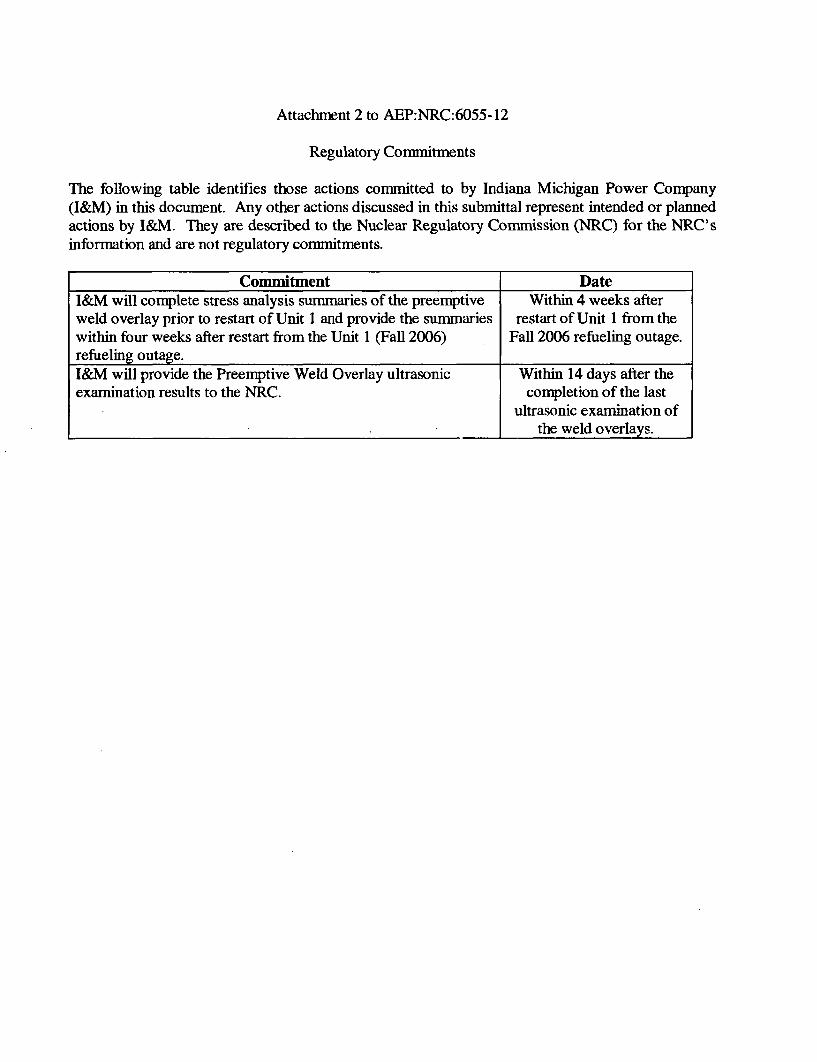
The following table identifies those actions committed to by Indiana Michigan Power Company(I&M) in this document. Any other actions discussed in this submittal represent intended or plannedactions by I&M. They are described to the Nuclear Regulatory Commission (NRC) for the NRC'sinformation and are not regulatory commitments.
Commitment DateI&M will complete stress analysis summaries of the preemptive Within 4 weeks afterweld overlay prior to restart of Unit 1 and provide the summaries restart of Unit 1 from thewithin four weeks after restart from the Unit 1 (Fall 2006) Fall 2006 refueling outage.refueling outage.I&M will provide the Preemptive Weld Overlay ultrasonic Within 14 days after theexamination results to the NRC. completion of the last
ultrasonic examination ofthe weld overlays.