indian payload capabilities for space …...indian payload capabilities for space missions a.s....
TRANSCRIPT

INDIAN PAYLOAD CAPABILITIES FOR SPACE MISSIONS
A.S. Kiran Kumar Director
Space Applications Centre Ahmedabad
5th I
nter
natio
nal A
STR
OD
Sym
posi
um,
July
11-
13, B
anga
lore

CARTOSAT-2/2A/2B (2007/2009/2010)
PAN
CARTOSAT-1 (2005) STEREOPAN
OCEANSAT-2 (2009) OCM/ SCAT/ROSA
RISAT-1 (2012) C-band SAR
TES(2001) Step& Stare
PAN
RESOURCESAT-1 (2003) LISS 3/ LISS 4 AWiFS
IMS-1(2008) MX/ HySI-T
RESOURCESAT-2 (2011)
LISS 3/ LISS 4/AWiFS
KALPANA-1 (2002) VHRR
INSAT-3A (2003) VHRR, CCD
YOUTHSAT(2011) LiV HySI/RaBIT
Megha-Tropiques (2011) MADRAS/SAPHIR/ScARaB/ ROSA
Application-specific EO payloads (O
pera
tiona
l)

OCEANSAT-3 OCM , TIR
RISAT-1R C-band SAR
RESOURCESAT-3 LISS 3/LISS 4/ AWiFS
RESOURCESAT-2A LISS3/LISS4/AWiFS
GISAT MXVNIR/SWIR/ TIR/HySI
INSAT- 3D Imager/Sounder
SARAL Altimeter/ARGOS
RESOURCESAT-3A/3B/3C LISS 3/LISS 4/AWiFS
GISAT MXVNIR/SWIR/TIR/HySI
Application-specific EO payloads (P
lanne
d)
CARTOSAT-2C/2D PAN
CARTOSAT-3 PAN
RISAT-3 L-band SAR

EARTH OBSERVATION (LAND AND WATER)
RESOURCESAT-1
RESOURCESAT-2 RISAT-1 IMS-1
GISAT RESOURCESAT-3
RISAT-3 RISAT-1R
RESOURCESAT-2A
RESOURCESAT-3A/3B/3C

EARTH OBSERVATION (CARTOGRAPHY)
CARTOSAT-1
RISAT-1
RISAT-3 RISAT-1R
TES
CARTOSAT-2/2A/2B
CARTOSAT-2C/2D
CARTOSAT-3

EARTH OBSERVATION (ATMOSPHERE & OCEAN)
INSAT-3D
SARAL
KALPANA-1
INSAT- 3A
GISAT MEGHA–TROPIQUES
OCEANSAT-2
OCEANSAT-1
OCEANSAT-3
YOUTHSAT


Payload Sensors in operation
Spatial Res. Swath/ Coverage (km)
Radiometry Spectral bands Repetivity/ revisit
CCD 1 1 Km India & surround.
10 bits 3 (B3, B4, B5) 4 times/ day
VHRR 2 2 km VIS 8 km WV/IR
Earth Disc 10 bits 3 Every ½ hrs
HySI/ IMS 1 500 m 128 12 bits 64 24 days OCM-2 1 360m 1420 12 bits 8 2 days
AWiFS 2 56 m 740 10/12 bits 4(B2,B3, B4, B5) 5 / 2.5 days
MX/ IMS 1 37 m 148 10 bits 4(B1, B2,B3, B4) 24 days LISS3 2 23 m 140 7/10 bits 4(B2,B3, B4, B5) 24/12 days LISS4 2 5.8 m 23/70 7/10 bits 3(B2,B3, B4) 40/ 5 days
PAN (stereo) 1 2.5 m 30 10 bits 1 100 days
PAN (mono) 4 0.8/ 1 m 10 / 16 10 bits 1 5 day revisit
Current observation capabilities : Optical

Current observation capabilities : Microwave
Payload Spatial Res. Swath km Radiometry Frequency Repetivity/revisit
Scatterometer 50 Km 1400 10 bits Ku band 2 days
SAR-X 1m to 8m 10 to 120 10 bits X 2days
SAR-C 1m to 50m 10 to 220 10 bits C 25/7days
Payload Spatial Res. Swath Frequency bands
Repetivity/revisit
MADRAS 6km to 40 km 1700 5 (18.7 to 157GHz) Multiple observations per day SAPHIR 10 km 1700 6 @183 GHz
ScARaB 40 km 2240 4
ROSA L1,L2 ~600 occultaions per day

Indian Imaging Capabilities - from Kilometer to sub-Meter
360m
23m
188m
1 Km BHASKARA TV PAYLOAD
1km
2.5m
< 1m
56m
73m
36m
5.8m
OCM
WiFS
LISS-1
AWiFS
LISS-2
LISS-3
LISS-4
PAN CARTO-1
INSAT-CCD < 1m
CARTOSAT-2 PAN 1 Km BHASKARA TV
PAYLOAD
PAN CARTO-2

Imaging Sensor for Earth Observation Cartographic applications
IRS-PAN
Cartosat 1 PAN Cartosat 2 PAN
TES-PAN
0.8 m
1 m
2.5 m
5.8 m

CARTOSAT-2C/2D ORBIT 500km POLAR SSO
PAYLOADS HIGH-RESOLUTION PANCHROMATIC (PAN) HIGH-RESOLUTION MULTI-SPECTRAL (MX)
PAN PAYLOAD FEATURES
Spectral bands PAN: 0.45-0.9 µm Resolution 0.64m Swath 10Km Quantization 11 bits SWR >10% SNR >180
TELESCOPE
FOCAL PLANE
CAMERA ELECTRONICS
MX PAYLOAD FEATURES
Spectral bands VIS1: 0.45-0.52 µm VIS2: 0.52-0.59 µm VIS3 : 0.62-0.68 µm VIS4 : 0.77-0.86 µm Resolution 1.6m Swath 10Km Quantization 11 bits SWR >20% SNR >500
Compact focal plane providing continuous imaging line (16000 pixels)
Time-delay-and-integration (TDI) CCD based detection system

0.25 m GSD PAN 0.5 m, 4 band MX 5 m MIR or 30m VNIR+ SWIR HySI CONTINUOUS IMAGING
PANMx
MIR
2700
1690
CARTOSAT-3 series
Mirror light-weighted 420 to 70 kg HexaPod High speed FECE
Optical Butting Test bench
Cartosat-3 series (3, 3A, 3B) 0.25m GSD PAN , 1m Mx and~5m MWIR 16km swath TDI CCD based imager Can provide 64000 Square kilometer data per orbit 6400 sq km imaging per orbit

Indian Mini-Satellite
HySI Payload
FCC with Classes
HySI Image Cube Jalgaon Area, 03-Jun-2008
4 Band, 36m GSD with a swath of ~ 140 Km Mx-Imager
Crop Classification using HySI Data 64 bands; 400-950 nm range; Spectral separation 8 nm; Spatial Res. 500 m; Swath 129.5 km

• C-band SAR
• Single/dual/quad polarisation
• Imaging with 1-50m resolution
• 10-240 km SWATH
RISAT-1


Radar Imaging Satellite (RISAT-1R)
Swath: 30-40-240 (in Km) Resolution:1- 3-9-25=50 ( m) C-band SAR with active-antenna Electronic beam steering Single/dual/quad polarization
Scan-SAR
Strip-Map
Spot-Light
Multi Resolution
Multi Swath
Multi-Polarization
107 kms 659 kms
Near-Swath
Spotlight
Far-Swath
+Pitch
ScanSAR
-Pitch
StripMap
536k
ms
Spot Mode: = 1 m, σo = -16dB Stripmap Mode: 3 - 6 m, σo = -17dB ScanSAR Mode1: 25 m, σo = -17dB ScanSAR Mode2: 50 m, σo = -17dB

INSAT-3D Met. Payloads 6 channel Imager 19 channel Sounder
• Visible to Thermal IR
• 1KM to 8KM IGFOV
• Half hourly earth coverage
• Flexible scanning modes
• Programmable number of lines and frame repeats
• Improved Blackbody calibration scheme
• Image motion & mirror motion compensation
• Visible to Lon. Wave IR
• Fully programmable East-West and North –South Scan pattern
• Programmable dwell time for East-West scan step motion
• Automatic space view every 2 min and Blackbody view every 30min.
• 10KM IGFOV, 14bits digitization
• Image motion & Mirror motion compensation

Visible
SWIR MIR WVP TIR-1 TIR-2
6 Channel Imager
24°
19°
Scan Modes: Normal: Full Earth Disk, 18°x18° in 24°x19° FOR (<27min) Programme: No. of Scan lines and No. of Image repeats programmable. Can be placed anywhere in FOR
Channel
(NE∆T@300K)
Spectral Band (µm)
Spatial Resolution
at Nadir (km)
VIS (SNR>150)
0.55-0.75 1 km
SWIR (SNR>150)
1.55-1.70 1 km
MIR (1.4K)
3.80-4.00 4 km
WV (1.0K@230K)
6.5-7.1 8 km
TIR-1 (0.35K)
10.3-11.3 4 km
TIR-2 (0.35K)
11.5-12.5 4 km

VIS 0.67-0.72um
SWIR 3.67-4.59um
MWIR 6.38-11.33um
LWIR 11.66-14.85um
6Ch 5Ch 7Ch
19 Channel Sounder
24°
19°
24°
19°
Minimum: 1° x 1° (640x640KM) in 1.7min, anywhere in FOR of 24° x19 ° Maximum: 15° x 15° (9600KMx9600KM) in ~400min, anywhere in FOR
Sounder Modes: Programmable Sounding Area: Programmable Space view Direction selection Selection of Dwell time on each scene: 0.1, 0.2 or 0.4s

Megha-Tropiques (ISRO-CNES Collaboration) Studying water cycle and energy exchanges in Tropical-belt
• MADRAS: – Precipitation and cloud properties – Total-power radiometer with Conical scanning – 5 frequencies (18.7GHz – 157GHz) • ScaRAB: Outgoing fluxes at TOA – Four Channel Earth Radiation budget at 0.5-0.7 μm, 0.2-4 μm, 0.2-50
μm & 10.5-12.5 μm – Resolution: 40 Km, Swath: 2242 Km • SAPHIR: Water vapour profile – mmW HSU at 183 GHz, 6-Ch Sounder – Brightness-Temperature 4K-313K – Resolution: 10 km & Swath: 1705 km • ROSA: GPS based Two Frequency Receivers L1 (1575.42 MHz) & L2
(1227.60MHz)
SAPHIR SCARAB
ROSA
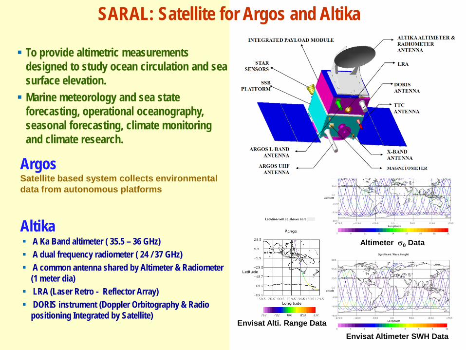
A Ka Band altimeter ( 35.5 – 36 GHz) A dual frequency radiometer ( 24 / 37 GHz) A common antenna shared by Altimeter & Radiometer
(1 meter dia) LRA (Laser Retro - Reflector Array) DORIS instrument (Doppler Orbitography & Radio
positioning Integrated by Satellite)
To provide altimetric measurements designed to study ocean circulation and sea surface elevation. Marine meteorology and sea state
forecasting, operational oceanography, seasonal forecasting, climate monitoring and climate research.
Argos Satellite based system collects environmental data from autonomous platforms
Envisat Altimeter SWH Data
Altimeter σ0 Data
Envisat Alti. Range Data
SARAL: Satellite for Argos and Altika
Altika

High Resolution Imaging Sensors on GEO Platform
High resolution Multi-spectral VNIR
Ground Resolution : 50 meters
Hyper-spectral VNIR
Ground Resolution : 500 meters
Hyper-spectral SWIR
Ground Resolution : 500 meters
Multi-channel IR
Ground Resolution : 1500 meters
GISAT
Scanning Modes: Full globe (18x18 deg) Sub continent (10x12 deg) User defined area scanning

PLANETARY/SPACE EXPLORATION
ADITYA
MARS MISSION
CHANDRAYAAN-2
ASTROSAT
CHANDRAYAAN-1

Laser Ranging
Terrain Mapper
Hyper Spectral Imager
Moon Impact Probe Trans Lunar
Injection
Mid Course Correction
GTO
ETO
Lunar Transfer Trajectory
Initial Orbit ~ 1000 km
Lunar Insertion Manoeuvre
Final Orbit 100 km Polar
Moon at Launch
Star Trackers
Sun Sensors
Gyroscope
Accelerometer
Altimeter
Pressure & Temp Sensors
Chandrayaan-1
Payloads Guidance & Control System

Lunar Impact Craters
Dark Haloed crater Ray Crater
TMC images of Chandrayaan-1

20 km
1
2
3
4
5 1
2
3
4
5 23 Nov 2008
Detection of Lunar rock types using HySI reflectance data
1. Plagioclase 2. Iron bearing minerals on
Basaltic terrain 3. Highland soils 4. Iron rich rocks on
Highland terrain 5. Mare soils
Mare Orientale is one of the youngest basin on the Moon surface. Location of Mare Orientale is shown as red dot on extreme left Lunar composite image. The HySI image from Chandrayaan-1 data represent sixty four colour of Lunar surface. The reflectance curves generated from HySI data helps us to identify highland and basaltic rocks on Moon.
Lunar Mineralogy : HySI data

Chandrayaan-2 Mission
• GSLV launch with a weight of ~2,650 kg • Orbiter & Lander
• Indian Rover
• Orbiter Payloads - Soft X-ray spectrometer - L & S band mini SAR - Imaging IR spectrometer - Neutral mass spectrometer - Terrain Mapping Camera
• Rover Payloads - Laser Induced Breakdown spectroscopy - Alpha particle induced X-ray spectroscopy

Fore Optics telescope
Three mirror
Slit
Spectrometer
Convex grating
Detector
250 mm
200 mm
Fore Optics telescope
Three mirror
Slit
Spectrometer
Convex grating
Detector
250 mm
200 mm
Chandrayaan-2 Electro-Optical Payloads
Footprint: 10 m X 10 m Along-track sampling: 5 m Swath : 40km
Terrain Mapping Camera-2 (TMC-2)
Camera weight 4 Kg FOV Imaging
1° along track 6.5° across track views: +25° , 0° , -25°
Size table
Direction EOM Elect. Pkg.
YAW 260 mm 192 mm
PITCH 200 mm 35 mm
ROLL 345 mm 172 mm
GIFOV 80m
Swath 40km
Spectral Range 0.8-5.0 µm
Spectral Resolution <20 nm
Max. spectral bands 256
Regulated Power 7W + Detector cooler power
Weight 6.5kg
Micro Camera
- Event Monitoring Camera - Rover Arm Camera (RAC)
Camera Head (each)
Processing Electronics (for 2 Camera head)
Regulated Power (W) 500 mW 800 mW
Size (mm x mm) 40 X 40 X 20 100 X 100 X 30
Weight (g) <30 <300
Imaging IR Spectrometer (IIRS)

ADITYA A Space based Advanced Solar Coronagraph
to study solar Corona in Visible and NIR wavelengths
Observe Oscillations of coronal structures Polarization of light: Study of magnetic field Detect “start” of coronal mass ejection
inputs for Space-Weather

ASTROSAT – versatile space based observatory
LAXPC SXT
SSM
UVIT
CZTI
India’s first dedicated multi-wavelength astronomy satellite with a capability to observe target sources in wide spectral
coverage extending over visible, ultraviolet, soft x-ray and hard x-ray regions with co-
aligned instruments simultaneously
• Large Area X-ray Proportional Counters (LAXPCs)
• Cadmium zinc Telluride Imager (CZTI)
• Soft X-Ray Telescope (SXT) • Ultraviolet Imaging Telescope
(UVIT) • Scanning Sky Monitor (SSM)

OPTICAL SYSTEMS
REFRACTIVE
ALL REFLECTIVE
CATADIOPTRIC MULTI-MIRROR
Double Gauss Telecentric
Cassegrain Three-mirror Anastigmat UNOBSCURED)
Ritchy Cassegrain with FCO
Φ570
Primary mirror
mirror
Interference FCO
Prism
FOV <40°
EFL < 0.7m
FOV < 90°
EFL:very small focal lengths~25mm
FOV < 3°
EFL:Large focal length~15m
FOV ~ 10°
EFL< 3 m
FOV ~ 3°
EFL: Large focal length~15m
Korsch TMA
FOV < 3°
EFL: Very Large focal length~ 30m

Optical System - Technologies
Optical Fabrication Computer aided polishing Ion Beam figuring Stressed mirror polishing
Light Weighting Scooping from rear Honey Comb structures Frit bonding
Opto-Mechanical Engineering Optical performance simulation FE computation Gravity unloaders for large mirrors
Optical Metrology Mirror testing using CGH Interferometric aided alignment
Honey comb structure
Gravity unloader concept

Near ideal electro-optical system performance
Ideal Detector: 100% Photons Detected with 63% MTF Nyquist Measures Photon wavelength Time of Photon arrival Detects Polarization
Telescope: Collects incoming EM energy Defines the spatial resolution Diffraction limited MTF Negligible Stray light
Optics: Corrects for the aberrations Diffraction limited performance along the field Performs Optical filtering Polarization selection Registered bands

Imaging Sensors Evolution
MCT/CMOS linear array
Single/ multi element detector
MCT array on Si readout circuit
Sensor Chip Assembly
Camera on chip
QWIP Device Focal plane array
ASIC for TR Control
Detector Wavelength (m) Si 0.2 - 1.1 Ge 0.4 - 1.8
InGaAs 1.0 - 3.8 InSb 1.0 - 7.0
InSb (77K) 1.0 - 5.6 HgSdTe (77k) 1.0 -25.0
Bhaskara IRS 1A/1B
IRS 1C/1D/P6
TES/CARTO
Imaging Technology
Frame Pushbroom Step & Stare
Resolution (m) 1000 72/36 5 1
Focal Length (mm)
Refractive (10-450) Reflective (~980)
Catadioptic (~5600)
Aperture (mm) 50 – 140 220 700
Detector Vidicon / vacuum tube
Linear array CCD / solid state
Data rate (Mbps) ~0.1 5-20 ~100 ~200
Platform Spin stabilised 3-axis stabilised Agile

Multi-spectral imager with high resolution (spatial, spectral and radiometric)
Filter: • Discrete filter • Strip filter • Filter overlaid on detector die
Detector: 1) Multi-linear detector for high BBR 2) Mechanically/optically butted array for Large swath 3) Area array overlaid with filter operated as multi-linear array 4) Multi-band detector
3 Separate Silicon Layers at Each Pixel
Different Colours Absorbed at
Different Depths

Hyper-spectral
Background can be reduced by – Low emissive mirrors and grating – Cold shield and cold stop at the exit pupil of the optics – cooling the spectrometer optics and its structure – Cooled Linear variable filter (LVF) – Cooled Multiple Strip filter


TECHNOLOGY EVOLUTION OPTICAL MICROWAVE
(BHASKARA) MULTI-SPECTRAL HIGH-RESOLUTION RADAR IMAGING
IMAGING TECHNOLOGY
FRAME IMAGER
PUSH-BROOM STEP & STARE Synthetic Aperture Radar
RESOLUTION 1000M 72/36M – 5M 0.8M 1M-50M
EM ENERGY COLLECTION
REFRACTIVE (10-450mm)
REFLECTIVE (~980mm)
CATADIOPTRIC (~5600mm)
ACTIVE ANTENNA
DETECTOR
VIDICON/ VACUUM TUBE
LINEAR ARRAY CCD/SOLID-STATE
LINEAR ARRAY CCD/SOLID-STATE
RECEIVE MODULES
ELECTRONICS CMOS LSTTL/STTL STTL/FTTL ASICS/ FTTL/ FPGA DATA RATE ~100 Kbps 5-20 Mbps – 100
Mbps ~ 200 Mbps
640 Mbps
PLATFORM
SPIN-STABILISED
3-AXIS STABILISED/ SUN-SYNCHRONOUS
AGILE 3-AXIS STABILISED/ SUN-SYNCHRONOUS
YEAR 1979 1988-2012 2001-2012
2012

55O
INSA
T-3E
G
SAT-
8
74O
INSA
T-3C
IN
SAT-
4CR
83O
INSA
T-3B
IN
SAT-
4A
93.5O
INSA
T-3A
IN
SAT-
4B
GSA
T-12
XPDR 55 deg E 74 deg E 83 deg E 93.5 deg E
INSAT-3E GSAT-8 INSAT-3C INSAT-4CR INSAT-3B INSAT-4A INSAT-3A INSAT-4B GSAT-12
MSS - - 1 SxC
- 1 SxC
- - - - 1 CxS 1 CxS
Ext. C 12 - 6 - 12 - 6 - 12 Nor. C 24 - 24 - - 12 12 12 -
Ku - 24 - 12 3 12 6 12 -
Others - - 2 BSS (C x S)
- - - - - -
TRANSPONDERS: PRESENT COMMUNICATION SATELLITES

Communication Payload Systems

Atomic Clock Monitoring Unit
NSGU
L5-Upconverter
S-Upconverter
HPA-150 W
HPA-250 W Helical Circular
Array Antenna Rb Atomic Clock
Frequency L5,S
Rb- Clocks Mod-Upconverter NSGU Dual Band Helical Array Antenna
ACMU

ASA/SAC/ISRO ASA/SAC/ISRO
2m Deployable Antenna on EV Top
EV Mounted Prime Focal Antenna
GSAT3
EV deployable & fixed Antennas
INSAT3
Onboard Reflector Antennas

ASA/SAC/ISRO ASA/SAC/ISRO
On Board C/Ku Band Shaped Antennas
INSAT-3C Antenna System
INSAT-4C Antenna System
INSAT-3E Antenna System
INSAT-4C Antenna System

ASA/SAC/ISRO ASA/SAC/ISRO
Near-Field diagnosis Module
COMPACT ANTENNA TEST RANGE
ANTENNA MESUREMENT FACILITY

ASA/SAC/ISRO
Remote sensing optical payloads Microwave payloads Communication and navigation payloads LEO- GEO-Lunar and planetary orbits Atomic clock developments

Thank You! A.S. Kiran Kumar
Director Space Applications Centre