index 536-002 guardrail transitions and … plans instructions topic no. 625-010-003 index 536-002...
TRANSCRIPT

Standard Plans Instructions Topic No. 625-010-003
Index 536-002 Guardrail Transitions and Connections for Existing Bridges FY 2018-19
1
Index 536-002 Guardrail Transitions and Connections for Existing Bridges Design Criteria NCHRP Report 350; AASHTO LRFD Bridge Design Specifications, 6th Edition, Section 13; Structures Design Guidelines (SDG); FDOT Design Manual (FDM)
Design Assumptions and Limitations Index 536-002 contains details for attaching guardrail approach transitions to Standard Plans 460 Series and 521 Series Indexes and also to existing safety shape bridge traffic railings.
The appropriate Index 536-002 approach transition retrofit for Standard Plans 460 Series and 521 Series Indexes must be selected and specified in the plans based on the shapes and designs of the existing bridge traffic railings, approach slabs and end bent wing walls. See the Standard Plans Instructions for Standard Plans 460 Series and 521 Series Indexes, FDM 215, and SDG 6.7 for more information.
The following three sections of instructions address the use of Index 536-002 with existing safety shape bridge traffic railings:
A Historical Compilation of Superseded Florida Department of Transportation "Structures Standard Drawings" for "F" and "New Jersey" Shape Structure Mounted Traffic Railings
Guardrail Approach Transition Retrofit Instructions for Existing Flat Slab Bridges
Guardrail Approach Transition Retrofit Instructions for Existing Beam/Girder Bridges
Index 536-002 Thrie-Beam Guardrail transition retrofits are bolted to existing safety shape bridge traffic railings through field drilled holes utilizing the pre-drilled Thrie-Beam Terminal Connector as a template. This method of attachment creates the potential for conflicts between the new attachment bolts and existing utilities and/or conduits. Compare the locations of the new attachment bolts with the positions of any existing utilities and/or conduits. Guidance is provided on Index 536-002 for selecting a bolt pattern for the Thrie-Beam Terminal Connector that may avoid existing utilities and/or conduits. Existing utilities and/or conduits that conflict with the possible bolt patterns shall be relocated if possible or placed out of service. Include all necessary utility adjustment information in the Roadway Plans.

Standard Plans Instructions Topic No. 625-010-003
Index 536-002 Guardrail Transitions and Connections for Existing Bridges FY 2018-19
2
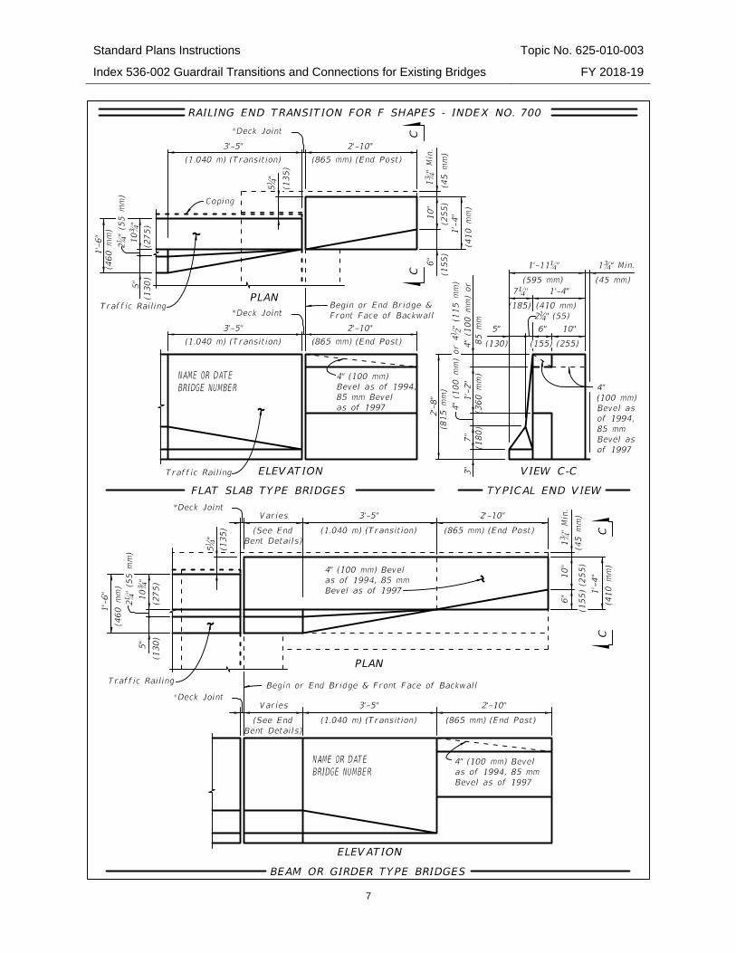
1. A Historical Compilation of Superseded FDOT Structures Standard Drawings for "F" and "New Jersey" Shape Structure Mounted Traffic Railings:
The following list of superseded standard drawings and associated railing typical sections and end transition details are presented as a historical reference for use when evaluating existing safety shape structure mounted traffic railings.
Utilities and/or conduits may exist in or adjacent to existing traffic railings and will vary in size, number and location. Utilities and/or conduits are not shown on these railing typical sections or end transition details.
Welded Wire Reinforcing (WWR) may have been used in place of the conventional reinforcing steel shown on the railing typical sections. Reinforcing steel was not standardized for railing end transitions but was instead included with the end bent reinforcing steel as a project specific design. Thus, some degree of variability can be expected for this reinforcing steel.
Superseded FDOT Structure Mounted Traffic Railing Standards Standard Index No. Railing Type Drawing
Date Revision Date(s)
11407 New Jersey 3/74 10/74 11407 New Jersey 3/78 10/77, 1/78, 9/78, 7/80, 3/81 &
8/81 11460 New Jersey 5/74 6/75, 8/75, 10/77, 9/78, 3/80,
7/80, 3/81, 8/81 & 5/82 12670 New Jersey 3/78 1/81 & 8/81 12931 New Jersey 1/79 3/81, 8/81, 10/84 & 11/84 13857 New Jersey 10/83 11/84 14101 New Jersey 1/86 N.A. 14286 F 9/87 10/87, 11/87, 12/87 & 1/88
700 (English Units) F 2/89 1990, 1992 & 1994 700 (Metric Units) F 2/89 1994, 1996, 1997 & 1998

Standard Plans Instructions Topic No. 625-010-003
Index 536-002 Guardrail Transitions and Connections for Existing Bridges FY 2018-19
3

Standard Plans Instructions Topic No. 625-010-003
Index 536-002 Guardrail Transitions and Connections for Existing Bridges FY 2018-19
4

Standard Plans Instructions Topic No. 625-010-003
Index 536-002 Guardrail Transitions and Connections for Existing Bridges FY 2018-19
5

Standard Plans Instructions Topic No. 625-010-003
Index 536-002 Guardrail Transitions and Connections for Existing Bridges FY 2018-19
6
Standard Plans Instructions Topic No. 625-010-003
Index 536-002 Guardrail Transitions and Connections for Existing Bridges FY 2018-19
7

Standard Plans Instructions Topic No. 625-010-003
Index 536-002 Guardrail Transitions and Connections for Existing Bridges FY 2018-19
8
2. Guardrail Approach Transition Retrofit Instructions for Existing Flat Slab Bridges:
These instructions are applicable only to bridges with concrete flat slab superstructures.
The retrofitting of existing W-beam guardrail transitions is accomplished by installing new Thrie-Beam Guardrail transitions in accordance with Scheme A or Scheme B as presented herein. It is permissible to use both Scheme A and Scheme B on a single bridge as required; e.g. Scheme A at begin bridge and Scheme B at end bridge. Scheme A shall be considered as the preferred choice for retrofitting the existing guardrail transitions. Scheme B should only be used where Scheme A is not applicable. Use of either scheme is dependent on the existing Traffic Railing and End Transition being in sound structural condition, for the portions that will remain in place.
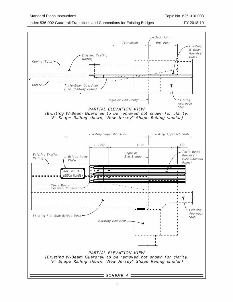
Flat Slab Scheme A The Thrie-Beam Guardrail transition retrofit details shown in Scheme A are applicable for existing bridges meeting both of the following requirements:
The existing bridge Traffic Railings are "F" or "New Jersey" shape railings conforming to one of the superseded FDOT standard designs shown in Section 1 of these Instructions (see above).
The total amount of thermal movement at the bridge end expansion joint does not exceed 1½" (¾" in each direction). The total amount of thermal movement at the expansion joint shall be determined by theoretical calculation and confirmed by field measurement where possible. It should be noted that the actual in-service movement due to thermal effects may be less than the value determined by theoretical calculation.
If both of the above requirements cannot be met, then Scheme B shall be evaluated for use. If both of the above requirements are met, the Scheme A details shown below and the following guidelines shall be used to assist in the preparation of the plans.
Generally, if Scheme A is applicable, Structures Plans will not be required for the Thrie-Beam Guardrail transition retrofit. Only Roadway Plans which include a reference to the Index 536-002, Sheet 24 of 24, Scheme I are required.
Standard Plans Instructions Topic No. 625-010-003
Index 536-002 Guardrail Transitions and Connections for Existing Bridges FY 2018-19
9

Standard Plans Instructions Topic No. 625-010-003
Index 536-002 Guardrail Transitions and Connections for Existing Bridges FY 2018-19
10
Flat Slab Scheme B The Thrie-Beam Guardrail transition retrofit details shown in Scheme B are applicable for existing bridges meeting both of the following requirements:
The existing bridge Traffic Railings are "F" or "New Jersey" shape railings conforming to one of the superseded FDOT standard designs shown in Section 1 of these Instructions (see above).
The total amount of thermal movement at the bridge end expansion joint exceeds 1½" (¾" in each direction). The total amount of thermal movement at the expansion joint shall be determined by theoretical calculation and confirmed by field measurement where possible. It should be noted that the actual in-service movement due to thermal effects may be less than the value determined by theoretical calculation.
If both of the above requirements are met, then Scheme B details shown below and the following guidelines shall be used to assist in the preparation of the plans.
If Scheme B is used, then Structures and Roadway Plans will be required for the Thrie-Beam Guardrail retrofit. The Roadway Plans shall address traffic control issues, removal of the existing W-Beam Guardrail transition connection and installation of the new Guardrail transition connection utilizing Index 536-001. The Structures Plans shall address demolition and reconstruction of the required portion of the existing Traffic Railing end transition and approach slab.
If the existing traffic railing is a 32” or 42” F-Shape traffic railing not listed in Section 1 of these Instructions (i.e. 1998 to FY 2017-18 Design Standards), the existing thrie-beam approach transition may remain in place in accordance with FDM 215. If the transition must be replaced project specific details will be required in the Plans. Applicable details from Indexes 400-090 or 400-091 shall be used for the approach slab reconstruction, if needed.
If the existing traffic railing is a "New Jersey" Shape traffic railing, project specific railing details will be required. Applicable details from Indexes 400-090 or 400-091 shall be used as required for the approach slab reconstruction.

Standard Plans Instructions Topic No. 625-010-003
Index 536-002 Guardrail Transitions and Connections for Existing Bridges FY 2018-19
11

Standard Plans Instructions Topic No. 625-010-003
Index 536-002 Guardrail Transitions and Connections for Existing Bridges FY 2018-19
12
3. Guardrail Approach Transition Retrofit Instructions for Existing Beam/Girder Bridges
These instructions are applicable only to bridges with beam or girder superstructures.
The retrofitting of existing "W" beam guardrail transitions is accomplished by installing new Thrie-Beam Guardrail transitions in accordance with Schemes A, B or C as presented herein. It is permissible to use any combination of Schemes A, B and C on a single bridge as required; e.g. Scheme A at begin bridge and Scheme C at end bridge. Schemes A and B shall be considered as the preferred choices for retrofitting the existing guardrail transitions. Scheme C should only be used where Schemes A or B are not applicable. Use of any schemes is dependent on the existing Traffic Railing and End Transition being in sound structural condition, for the portions that will remain in place.
Beam/Girder Scheme A The Thrie-Beam Guardrail transition retrofit details shown in Scheme A are applicable for existing bridges meeting both of the following requirements:
The existing bridge Traffic Railings are "F" or "New Jersey" shape railings conforming to one of the superseded FDOT standard designs shown in Section 1 of these Instructions (see above).
The existing end bent wingwalls that support the Traffic Railing end transitions are a minimum of 8'-9" in length and are directly supported by a pile or drilled shaft.
If both of the above requirements cannot be met, then Scheme B shall be evaluated for use. If both of the above requirements are met, the Scheme A details shown below and the following guidelines shall be used to assist in the preparation of the plans.
Generally, if Scheme A is applicable, Structures Plans will not be required for the Thrie-Beam Guardrail transition retrofit. Only Roadway Plans which include a reference to Index 536-002, Sheet 24 of 24, Scheme II are required.

Standard Plans Instructions Topic No. 625-010-003
Index 536-002 Guardrail Transitions and Connections for Existing Bridges FY 2018-19
13

Standard Plans Instructions Topic No. 625-010-003
Index 536-002 Guardrail Transitions and Connections for Existing Bridges FY 2018-19
14
Beam/Girder Scheme B The Thrie-Beam Guardrail transition retrofit details shown in Scheme B are applicable for existing bridges meeting both of the following requirements:
The existing bridge Traffic Railings are "F" or "New Jersey" shape railings conforming to one of the superseded FDOT standard designs shown in Section 1 of these Instructions (see above).
The total amount of thermal movement at the bridge end expansion joint does not exceed 1½" (¾" in each direction). The total amount of thermal movement at the expansion joint shall be determined by theoretical calculation and confirmed by field measurement where possible. It should be noted that the actual in-service movement due to thermal effects may be less than the value determined by theoretical calculation.
If both of the above requirements cannot be met then Scheme C shall be evaluated for use. If both of the above requirements are met, the Scheme B details shown below and the following guidelines shall be used to assist in the preparation of the plans.
Generally, if Scheme B is determined to be applicable, Structures Plans will not be required for the Thrie-Beam Guardrail retrofit. Only Roadway Plans which include a reference to Index 536-002, Sheet 24 of 24, Scheme III shall be used for the Thrie-Beam Guardrail retrofit.

Standard Plans Instructions Topic No. 625-010-003
Index 536-002 Guardrail Transitions and Connections for Existing Bridges FY 2018-19
15
Standard Plans Instructions Topic No. 625-010-003
Index 536-002 Guardrail Transitions and Connections for Existing Bridges FY 2018-19
16
Beam/Girder Scheme C The Thrie-Beam Guardrail transition retrofit details shown in Scheme C are applicable for existing bridges meeting both of the following requirements:
The existing bridge Traffic Railings are "F" or "New Jersey" shape railings conforming to one of the superseded FDOT standard designs shown in Section 1 of these Instructions (see above).
The total amount of thermal movement at the bridge end expansion joint exceeds 1½" (¾" in each direction). The total amount of thermal movement at the expansion joint shall be determined by theoretical calculation and confirmed by field measurement where possible. It should be noted that the actual in-service movement due to thermal effects may be less than the value determined by theoretical calculation.
If both of the above requirements are met then Scheme C shall be used for the retrofit. In this event, the details shown below and the following guidelines shall be used to assist in the preparation of the plans.
If Scheme C is determined to be applicable, then Structures and Roadway Plans will be required for the Thrie-Beam Guardrail retrofit. The Roadway Plans shall address traffic control issues, removal of the existing "W" Beam Guardrail transition connection and installation of the new Guardrail transition connection utilizing Index 536-001. The Structures Plans shall address demolition and reconstruction of the required portion of the existing Traffic Railing end transition and approach slab.
If the existing traffic railing is a 32” or 42” F-Shape traffic railing not listed in Section 1 of these Instructions (i.e. 1998 to FY 2017-18 Design Standards), the existing thrie-beam approach transition may remain in place in accordance with FDM 215. If the transition must be replaced project specific details will be required in the Plans. Applicable details from Indexes 400-090 or 400-091 shall be used for the approach slab reconstruction, if needed.
If the existing traffic railing is a "New Jersey" Shape traffic railing, project specific railing details will be required. Applicable details from Indexes 400-090 and 400-091 shall be used as required for the approach slab reconstruction.

Standard Plans Instructions Topic No. 625-010-003
Index 536-002 Guardrail Transitions and Connections for Existing Bridges FY 2018-19
17

Standard Plans Instructions Topic No. 625-010-003
Index 536-002 Guardrail Transitions and Connections for Existing Bridges FY 2018-19
18
Plan Content Requirements In the Roadway Plans: Include the following note in the General Notes:
Paint reinforcing steel that is exposed during drilling/coring of the Terminal Connector bolt holes with a zinc rich galvanizing compound in accordance with Specification 562.
Payment Item number Item Description Unit Measure
536-1-AA Guardrail - Roadway LF 536-8-AB Guardrail – Approach Transition to Rigid Barrier EA 536-73 Guardrail Removal LF
See the BOE and Specification 536 for additional information on payment, pay item use and compensation.