increasing the energy efficiency of an internal combustion
TRANSCRIPT

applied sciences
Article
Increasing the Energy Efficiency of an InternalCombustion Engine for Ship Propulsion withBottom ORCs
Melchiorre Casisi 1, Piero Pinamonti 1,* and Mauro Reini 2
1 Polytechnic Department of Engineering and Architecture, University of Udine, 33100 Udine, Italy;[email protected]
2 Department of Engineering and Architecture, University of Trieste, 34100 Trieste, Italy; [email protected]* Correspondence: [email protected]; Tel.: +39-320-4365861
Received: 24 July 2020; Accepted: 27 September 2020; Published: 2 October 2020
Abstract: The study examines the option of adding a bottom Organic Rankine Cycle (ORC) for energyrecovery from an internal combustion engine (ICE) for ship propulsion. In fact, energy recoveryfrom the exhaust gas normally rejected to the atmosphere and eventually from the cooling watercircuit (usually rejected to the sea) can significantly reduce the fuel consumption of a naval ICEduring its operation. In the paper, different possible bottom ORC configurations are consideredand simulated using the Aspen® code. Different working fluids are taken into account, jointly withregenerative and two-temperature levels designs. The energy recovery allowed by each solution isevaluated for different engine load, allowing the identification of the most suitable ORC configuration.For the selected case, the preliminary design of the main heat exchangers is carried out and theoff-design performance of the whole combined propulsion plant (ICE + ORC) is evaluated, leading toa preliminary analysis of cost saving during normal ship operation. The results of this analysis showan increase in power output of about 10% and an expected Payback Time of less than 6 years.
Keywords: Organic Rankine Cycle; ship engine; bottoming cycle
1. Introduction
The today’s cost of fossil fuels is constantly evolving. The present economic crisis, combined withpolitical pressures, make the price of oil strongly uncertain. In addition, in recent years, pollutingemissions produced by merchant ships have to be contained in increasingly restrictive limits to complywith the new regulations coming in force [1]. In this changing scenario, the need arises to explore thepossibility of using alternative fuels, instead of the traditional oil (heavy fuel oil -HFO) and to increasethe whole efficiency of the propulsion system.
From the point of view of alternative fuels, the research points towards fuels with economicallysound potentials and with limited impact on the environment. The technology development occurredin large gas engines during the recent years has achieved high thermal efficiency and low emissionsutilizing liquefied natural gas (LNG), suggesting this fuel as a potential substitute of HFO [2–4].Modern gas engines abate CO2 by 30%, NOx by 85% (without after treatments), ensuring the completeabsence of SOx compared to the correspondent engine, fed by liquid fuel oil [5]. In order to benefitfrom these advantages, the major engine manufacturers have designed several set of gas engine forboth ship propulsion and land based power generation, like the Wärtsilä 50DF series.
From the point of view of increasing the whole efficiency of the propulsion system, energy recoverycan be considered of the waste heat usually dissipated, for both improving the propulsion power or forproducing useful heat on board the ship [6–10]. In this context, the use of Organic Rankine Cycles (ORC)
Appl. Sci. 2020, 10, 6919; doi:10.3390/app10196919 www.mdpi.com/journal/applsci

Appl. Sci. 2020, 10, 6919 2 of 18
as bottom power plant of the main propulsion engine appears a very attractive technology, allowingefficiency gains equal, or higher, with respect to other energy saving solutions, like the adoption ofmore complex exhaust gas boilers, heat pumps [11,12], or a bottom Kalina cycle [13]. Many applicationsof this technology are made in land-based installations, such as biomass, solar and geothermal energyplant [14–18]. Recently, several studies have been conducted on the possible application of ORCgroups coupled to diesel engines, for both stationary and propulsion applications [19–21]. Specificapplication to marine propulsion system can be found in [22], where different hydrocarbons and somerefrigerant are considered as working fluids in both recuperated and non-recuperated cycles, in [23,24],where different refrigerant are considered as working fluids in simple and superheated cycles, in [25],where the whole heat exchangers network is designed using the pinch analysis, and in [26], where animportant excess of steam is supposed to be produced by the exhaust gas boiler and the energy recoverycan be performed by a cascade, made up by a steam Rankine cycle and a ORC. A similar cascade energyrecovery system is presented in [27], but the ORC is replaced by an absorption refrigeration machine.
This study examines the options of energy recovery from an ICE for ship propulsion by addinga bottom ORC, with the aim of reducing the fuel consumption of the propulsion system during itsoperation. Different possible bottom ORC configurations are considered and simulated using theAspen® code, and different working fluids are taken into account, jointly with regenerative andtwo-temperature levels designs, allowing the identification of the most suitable ORC configuration.
The proposed analysis is based on the real operating data of a marine engine, considering theneeds of its cooling system, and on the use of a realistic design/off-design simulator of the heatexchangers, available in Aspen®. In this way the expectation is to obtain very realistic values of theactual performance increase of the propulsion system. Therefore, a robust preliminary economic andenvironmental evaluation of the real operation of the ship engine can be performed.
The analysis is focused on increasing the efficiency of the on-board propulsion system, withoutconsidering the possibility of producing other energy carriers to meet the ship’s requests. A search foroptimal solutions to meet the entire energy demand on board of a cruise ship is presented for examplein [28].
2. Options of Waste Heat Recovery from a Naval Engine
In this study a dual fuel engine (model 6L50DF by Wärtsilä) for ship propulsion has beenconsidered. This engine model is a six cylinder in-line, it produces it 5.7 MW with efficiency ofabout 49%, operating at 514 rpm. It is very flexible from the fuel point of view: it can switch almostinstantaneously from gas (LNG) to liquid diesel (LFO-HFO), and vice versa, allowing the choose ofthe most suitable solution. Because of its complexity, a dual-fuel engine costs up to 30% more than atraditional diesel engine, but it allows an annual saving in term of fuel equal to 5–8% [5].
The benefits mentioned above can still be enhanced by recovering the thermal energy mainlyavailable in the exhaust gases and in other engine’s fluids, which is discharged to the environment inthe traditional propulsion plants.
The heat balance of a Wärtsilä 6L50DF engine shows about 11.5 MW of fuel input and a poweroutput of 5.7 MW, at maximum load (Figure 1). The remaining energy is rejected to the environmentby the exhaust gas (about 3.1 MW available at 400 C) and the cooling circuits (2.4 MW in LT andHT circuits).
The cooling circuit is split in two parts, according to the temperature level: a high temperaturecircuit (HT, at about 90 C) and a low temperature circuit (LT, at 50 C). It is worth nothing that theamount of energy rejected by the engine is about equally split between the exhaust gas and the twocooling circuits HT + LT together (56% and 44%, respectively, at the maximum engine load), but theexergy content of the exhaust gas is three times higher than that of the HT + LT circuits (74% and 26%,respectively, at the maximum engine load). Therefore, it can be inferred that a first selection of possibleenergy recovery can be based primarily on the availability of high temperature heat sources, namelythe exhaust gas and possibly the HT water circuit.

Appl. Sci. 2020, 10, 6919 3 of 18Appl. Sci. 2020, 10, x FOR PEER REVIEW 3 of 18
Figure 1. Energy balance of the engine W6L50DF [1].
To introduce the feasibility of the heat recovery, a brief description of the cooling circuits and of exhaust gas circuit of the engine W6L50DF is necessary (Figure 2).
Figure 2. Simplified schematic of the cooling circuits and exhaust gas of the engine W6L50DF.
The water of the high temperature fresh-water circuit (HT CIRCUIT) flows through the cylinder jackets, the cylinder heads and the first stage of the air-cooler, from the engine inlet (IM) to the engine
Figure 1. Energy balance of the engine W6L50DF [1].
To introduce the feasibility of the heat recovery, a brief description of the cooling circuits and ofexhaust gas circuit of the engine W6L50DF is necessary (Figure 2).
Appl. Sci. 2020, 10, x FOR PEER REVIEW 3 of 18
Figure 1. Energy balance of the engine W6L50DF [1].
To introduce the feasibility of the heat recovery, a brief description of the cooling circuits and of exhaust gas circuit of the engine W6L50DF is necessary (Figure 2).
Figure 2. Simplified schematic of the cooling circuits and exhaust gas of the engine W6L50DF.
The water of the high temperature fresh-water circuit (HT CIRCUIT) flows through the cylinder jackets, the cylinder heads and the first stage of the air-cooler, from the engine inlet (IM) to the engine
Figure 2. Simplified schematic of the cooling circuits and exhaust gas of the engine W6L50DF.
Appl. Sci. 2020, 10, 6919 4 of 18
The water of the high temperature fresh-water circuit (HT CIRCUIT) flows through the cylinderjackets, the cylinder heads and the first stage of the air-cooler, from the engine inlet (IM) to the engineoutlet (UM). The water in the low temperature fresh-water circuit (LT CIRCUIT) cools the second stageof the air-cooler and then the lubricant oil. The control of the HT circuit is based on the temperatureof the water leaving the engine. A three-way thermostatic valve set at 91 C re-circulates part of theflow (RIC) to keep the water inlet temperature at the right level. The remaining part of the water isthen cooled in a central cooler, dissipating heat into the sea water. A heat exchanger, high temperaturewaste heat recovery (HT WHR) allows the recovery of thermal energy from the HT cooling circuit.The object of this recovery is to allow the maximum power production from the bottom cycle, withoutpreventing the proper operation of the temperature control loop, therefore the extracted thermal powershall be equal to the engine thermal production, at each different load. The water at the outlet of theHT WHR returns to the engine inlet (RIT), with a possible integration from the LT circuit (REINT).In this way, the regulation system of the engine cooling guarantees, for all engine loads, a constanttemperature in the high temperature fresh water circuit, while the temperature of the low temperaturefresh water circuit does not exceed 50 C, but it strong depends on the engine load and on the seewater temperature. Therefore, an energy recovery from the LT circuit has to be regarded as not feasiblein practice.
3. First Plant Modeling and Choice of the Working Fluid
The goal of this study is the identification of the most suitable ORC configuration dedicated to theheat recovery from the engine Wärtsilä 6L50DF. The study is performed in three steps: first step is thechoice of the organic working fluid for the cycle, then it comes the thermodynamic analysis to optimizethe cycle and finally the component design. For these purposes it is useful the support of a computersoftware containing an extensive library of fluids, including all their chemical and thermodynamicproperties. The different plant solutions have been analyzed with the Aspen Plus® code, utilizing thestandard components of its library [29].
3.1. Choice of Working Fluid
As it is well known, the convenience of using systems based on ORC cycles lies primarily onfavorable characteristics of some organic liquids in comparison with water, i.e., larger molecular mass,lower critical temperature, lower critical pressure, lower condensation entropy and lower solidificationtemperature [30–32]. In fact, the feature that makes water unsuitable to use in applications of smallsize and low maximum temperature of the cycle, is its large entropy of evaporation, compared withthat of organic fluids. By using organic fluids, it is possible to operate with higher mass flow rates andlower expansion pressures, achieving a power output higher than that of a steam cycle working withthe same conditions.
In the present study four different pure substances are compared: benzene, cyclohexane,octa-methylsiloxane (MDM) and toluene. Cyclohexane, benzene and toluene are selected as workingfluids because they possess efficient thermal performance at high temperature, favorable environmentalcharacteristics and high decomposition temperatures [33]. MDM and toluene have already foundindustrial application in ORC cycles [34–36] with temperature of the heat source in the range 300–400 Cand electric power output greater than 100 kW. Different kinds of fluids are currently studied and usedfor lower temperatures of the heat source and small size of the system. In particular some studiesconsider the option of using refrigerant for waste heat recovery from small size ICEs [37–39]. It isworth noting that, for the typical hot source temperature of this application, the fluids considered inthe present study (in particular toluene and MDM) always obtain efficiencies close to the maximumachievable value [34], with small gaps with respect to the best performing fluid, if any. Obviously,different fluids are better suited for lower hot source temperature, like the isobutene introduced in theTwo-pressure-levels recovery system, presented further on in this paper.

Appl. Sci. 2020, 10, 6919 5 of 18
First, a simple Rankine cycle, according to the scheme shown in Figure 3, has been simulated withthe Aspen Plus® code considering each one of the four organic fluids. In order to assure safe operationon board of the ships, thermal oil is used as intermediate media between the exhaust gasses and theorganic fluid. The exhaust gasses flow rate and temperature are 9.2 kg/s and 400 C, respectively at100% of the nominal load and they change with load up to 5.3 kg/s and 442 C, respectively at 50% ofthe nominal load [5]. The thermal oil is heated in the heat exchanger at the left hand side in Figure 3,which is also shown as “Exhaust Gas Recuperator (optional)” at the top of Figure 2. In this preliminaryevaluation, nominal conditions only have been considered and the temperature and mass flow rateof the thermal oil have been fixed, jointly with the maximum and minimum pressures regarded asacceptable for the cycle, in order of obtaining a homogeneous comparison of the four fluids. In thedetailed design of the heat exchangers (Section 5), as well as in the off-design analysis of the ORCregenerated cycle Section 6), these limitations will be relaxed.
The following operating conditions and mass flow rates are set for all the organic working fluids,consistently with the hypothesis of recovering energy only from the exhaust gas of the engine Wärtsilä6L50DF:
• temperature of hot source (thermal oil Dowtherm-G®): 350 C;• mass flow rate of hot source (thermal oil Dowtherm-G® [40]): 5 kg/s;• maximum evaporating temperature of the organic fluid: 250 C;• maximum pressure of the organic fluid: 15 bar;• minimum condensing pressure of the organic fluid: 0.3 bar;
Appl. Sci. 2020, 10, x FOR PEER REVIEW 5 of 18
respectively at 50% of the nominal load [5]. The thermal oil is heated in the heat exchanger at the left hand side in Figure 3, which is also shown as “Exhaust Gas Recuperator (optional)” at the top of Figure 2. In this preliminary evaluation, nominal conditions only have been considered and the temperature and mass flow rate of the thermal oil have been fixed, jointly with the maximum and minimum pressures regarded as acceptable for the cycle, in order of obtaining a homogeneous comparison of the four fluids. In the detailed design of the heat exchangers (Section 5), as well as in the off-design analysis of the ORC regenerated cycle Section 6), these limitations will be relaxed.
The following operating conditions and mass flow rates are set for all the organic working fluids, consistently with the hypothesis of recovering energy only from the exhaust gas of the engine Wärtsilä 6L50DF:
• temperature of hot source (thermal oil Dowtherm-G®): 350 °C; • mass flow rate of hot source (thermal oil Dowtherm-G® [40]): 5 kg/s; • maximum evaporating temperature of the organic fluid: 250 °C; • maximum pressure of the organic fluid: 15 bar; • minimum condensing pressure of the organic fluid: 0.3 bar;
Figure 3. Flowchart of simple ORC circuit.
The final cold sink is the sea water. Considering a possible intermediate circuit, a precautionary value of 38 °C is assumed for the cooling fluid of the condenser of the energy recovery system. The working fluids flow rates have been determined by the standard Evaporator model of Aspen Plus® [29], starting from a tentative value (3 kg/s). The main components of the plant (Figure 3) have been modeled on the basis of the hypothesis below:
• Turbine (3-4): discharge pressure (minimum of the cycle) and isentropic efficiency are set constant.
• Condenser (4-1): it allows the condensation of the full amount of the working fluid, with no limits on the maximum temperature reached by the cold fluid.
• Circulation pump (1-2): output pressure is set constant (maximum of the cycle). • Evaporator (2-3): the outlet temperature of the working fluid has been fixed (maximum
temperature of the cycle); taking the maximum pressure into account, the full amount of the organic fluid may reach the state of dry saturated or superheated vapor.
A comparison of the results obtained for the different working fluids is shown in Table 1.
Figure 3. Flowchart of simple ORC circuit.
The final cold sink is the sea water. Considering a possible intermediate circuit, a precautionaryvalue of 38 C is assumed for the cooling fluid of the condenser of the energy recovery system.The working fluids flow rates have been determined by the standard Evaporator model of AspenPlus® [29], starting from a tentative value (3 kg/s). The main components of the plant (Figure 3) havebeen modeled on the basis of the hypothesis below:
• Turbine (3-4): discharge pressure (minimum of the cycle) and isentropic efficiency are set constant.• Condenser (4-1): it allows the condensation of the full amount of the working fluid, with no limits
on the maximum temperature reached by the cold fluid.• Circulation pump (1-2): output pressure is set constant (maximum of the cycle).• Evaporator (2-3): the outlet temperature of the working fluid has been fixed (maximum temperature
of the cycle); taking the maximum pressure into account, the full amount of the organic fluid mayreach the state of dry saturated or superheated vapor.

Appl. Sci. 2020, 10, 6919 6 of 18
A comparison of the results obtained for the different working fluids is shown in Table 1.
Table 1. Performance comparison of simple ORC cycles with different fluids.
Fluid Power Output Oil Out Temp. Efficiency
kW C %
Benzene 420 155 20.2Cyclohexane 411 147 18.7
MDM 97 276 12.5Toluene 364 174 20.6
This preliminary comparison shows that the most promising fluids appear to be benzene andtoluene. Toluene in particular allows to raise the evaporation temperature of the cycle at 290 C andthe maximum cycle pressure to 28 bar. Benzene and cyclohexane have a critical temperature below290 C, whilst MDM has a slightly higher critical temperature (291 C) but its adoption is convenient ininternal recuperated ORCs, due to the shape of its saturation curves in the T-s plane [41]. For toluene inaddition, it is possible to further reduce the condensing pressure to 0.1 bar, thanks to the temperature ofcold fluid source (see water), and a good resistance to degradation at high temperature (above 300 C)is also experimentally demonstrated for toluene [42]; this fluid is also less toxic than benzene.
Then, toluene has been identified as the best working fluid for the considered application.The results obtained in these new conditions are presented in Table 2. The optimization of the massflow rate of the chosen fluid allows an even higher maximum power of 611 kW to be obtained from thebottoming cycle, corresponding to a toluene mass flow rate of 3.5 kg/s.
As previously described, the engine releases also a flow of hot water (the HT cooling circuit) thatis an additional opportunity of energy recovery. This heat source is at low temperature (about 90 C),so that the fluids considered in Table 1 are not suitable for energy recovery in a Rankine cycle, becausethey are characterized by high boiling temperatures. In this case it would be appropriate using alow temperature boiling fluid, like isobutene, which has an evaporation temperature equal to −12 Cat 1 bar, a Tcr = 135 C and shows good performance in comparison with other hydrocarbons andrefrigerants at maximum cycle temperature of about 90 C [43].
Table 2. Performance obtained by a simple ORC with toluene, Tvap = 290 C, pvap = 28 bar, pcon = 0.1 bar.
Power output Oil Out Temp. Efficiency
kW C %
Toluene 523 145 25.8
Therefore, a simple Rankine cycle with isobutene as the working fluid has been simulated, alwaysaccording to the scheme in Figure 3. It has been coupled to the HT water circuit of the ICE, replacingthe heat exchanger “HT WHR (optional)” in Figure 2 with the evaporator of the ORC. The possibleoutput of the latter has been evaluated using a set of thermodynamic parameters consistent with theoperating conditions of the engine at maximum load [5]:
• temperature of HT water circuit (hot source): 91 C;• mass flow rate of HT water circuit: 37.5 kg/s;• evaporating temperature of the working fluid: 81 C;• maximum pressure of the working fluid: 13 bar;• condensing pressure of the working fluid: 6.5 bar;• tentative working fluid flow rate: 7 kg/s;• temperature of condenser cooling flow: 38 C.

Appl. Sci. 2020, 10, 6919 7 of 18
Under these conditions the additional power of 87 kW has been obtained from the low temperatureORC cycle, with an efficiency of 6.1%.
3.2. Functional Parameters of the ORC at ICE Part Load
A sensitivity analysis has been performed on the main parameters of the cycle at five engineoperation points (100%, 85%, 75%, 50%, 25% of nominal load), obtaining information on the maximumexpected performance of the ORC, in consequence of changing in the flow rate and temperature ofexhaust gases, that change as the engine load varies, modifying the energy available for the bottom cycle.In this sensitivity analysis, the upper and lower temperature and pressure of a simple Rankine cyclewith toluene have both been varied, according to the power recovered from the engine exhaust gases.
The cycle’s powers and efficiencies achieved changing the maximum pressure are shown inFigures 4 and 5. Increasing the maximum pressure, the efficiency has a monotonous increasing trend,but the power is about constant in the range 20–30 bar, showing that the cycle efficiency increase iscompensated by a reduction in the energy recovery from exhaust gas. Therefore, a maximum pressureof 20 bar has been assumed in the further evaluations.
Figure 6 shows that a significant increase in power output can be obtained by considering theengine operating in a cold sea. The condensation pressure, for the considered temperatures range,is from 0.04 to 0.1 bar. The power increases with decreasing the condensation temperature, as it isexpected for a Rankine cycle. When condensation temperature can be kept at about 27 C (as it ispossible only if see water temperature is below 20 C) the power output shows a surplus of about100 kW, with respect to full load operation with a condensation temperature of 46 C. The efficiency alsoincreases with decreasing the condensation temperature, varying between 23% and 25.3%, with verylimited influence, however, by the engine load.
Appl. Sci. 2020, 10, x FOR PEER REVIEW 7 of 18
3.2. Functional Parameters of the ORC at ICE Part Load
A sensitivity analysis has been performed on the main parameters of the cycle at five engine operation points (100%, 85%, 75%, 50%, 25% of nominal load), obtaining information on the maximum expected performance of the ORC, in consequence of changing in the flow rate and temperature of exhaust gases, that change as the engine load varies, modifying the energy available for the bottom cycle. In this sensitivity analysis, the upper and lower temperature and pressure of a simple Rankine cycle with toluene have both been varied, according to the power recovered from the engine exhaust gases.
The cycle’s powers and efficiencies achieved changing the maximum pressure are shown in Figures 4 and 5. Increasing the maximum pressure, the efficiency has a monotonous increasing trend, but the power is about constant in the range 20–30 bar, showing that the cycle efficiency increase is compensated by a reduction in the energy recovery from exhaust gas. Therefore, a maximum pressure of 20 bar has been assumed in the further evaluations.
Figure 6 shows that a significant increase in power output can be obtained by considering the engine operating in a cold sea. The condensation pressure, for the considered temperatures range, is from 0.04 to 0.1 bar. The power increases with decreasing the condensation temperature, as it is expected for a Rankine cycle. When condensation temperature can be kept at about 27 °C (as it is possible only if see water temperature is below 20 °C) the power output shows a surplus of about 100 kW, with respect to full load operation with a condensation temperature of 46 °C. The efficiency also increases with decreasing the condensation temperature, varying between 23% and 25.3%, with very limited influence, however, by the engine load.
Figure 4. ORC output power vs. maximum cycle pressure, for different engine loads (cooling water temperature equal to 38 °C). Figure 4. ORC output power vs. maximum cycle pressure, for different engine loads (cooling watertemperature equal to 38 C).

Appl. Sci. 2020, 10, 6919 8 of 18
Appl. Sci. 2020, 10, x FOR PEER REVIEW 8 of 18
Figure 5. ORC efficiency vs. maximum cycle pressure, for different engine loads (cooling water temperature equal to 38 °C).
Figure 6. ORC power vs. condensation temperature, for different engine loads and maximum pressure equal to 20 bar.
4. Choice of Optimal Bottoming Cycle Configuration
In the next step of the study, an assessment of different configurations of the ORC bottoming thermodynamic cycle has been made. The criteria used for choosing pressures and temperatures for each configuration are those that allow to maximize the power produced by the cycle for each level of output of the engine. At this stage, the constraints related to the real geometrical dimensions of the heat exchangers are not explicitly taken into account; they will be introduced in the next step, in view of the economic evaluation of the chosen solution.
The following parameters have been kept constant for all engine load:
• cycle maximum pressure 20 bar (in order to avoid stressing pipes and components); • cycle maximum temperature 290 °C (in order to obtain a slight overheating above the toluene
saturation temperature at 20 bar (260 °C), and below the degradation limit for the same fluid); • condensing mass flow rate 80 kg/s;
Figure 5. ORC efficiency vs. maximum cycle pressure, for different engine loads (cooling watertemperature equal to 38 C).
Appl. Sci. 2020, 10, x FOR PEER REVIEW 8 of 18
Figure 5. ORC efficiency vs. maximum cycle pressure, for different engine loads (cooling water temperature equal to 38 °C).
Figure 6. ORC power vs. condensation temperature, for different engine loads and maximum pressure equal to 20 bar.
4. Choice of Optimal Bottoming Cycle Configuration
In the next step of the study, an assessment of different configurations of the ORC bottoming thermodynamic cycle has been made. The criteria used for choosing pressures and temperatures for each configuration are those that allow to maximize the power produced by the cycle for each level of output of the engine. At this stage, the constraints related to the real geometrical dimensions of the heat exchangers are not explicitly taken into account; they will be introduced in the next step, in view of the economic evaluation of the chosen solution.
The following parameters have been kept constant for all engine load:
• cycle maximum pressure 20 bar (in order to avoid stressing pipes and components); • cycle maximum temperature 290 °C (in order to obtain a slight overheating above the toluene
saturation temperature at 20 bar (260 °C), and below the degradation limit for the same fluid); • condensing mass flow rate 80 kg/s;
Figure 6. ORC power vs. condensation temperature, for different engine loads and maximum pressureequal to 20 bar.
4. Choice of Optimal Bottoming Cycle Configuration
In the next step of the study, an assessment of different configurations of the ORC bottomingthermodynamic cycle has been made. The criteria used for choosing pressures and temperatures foreach configuration are those that allow to maximize the power produced by the cycle for each level ofoutput of the engine. At this stage, the constraints related to the real geometrical dimensions of theheat exchangers are not explicitly taken into account; they will be introduced in the next step, in viewof the economic evaluation of the chosen solution.
The following parameters have been kept constant for all engine load:
• cycle maximum pressure 20 bar (in order to avoid stressing pipes and components);• cycle maximum temperature 290 C (in order to obtain a slight overheating above the toluene
saturation temperature at 20 bar (260 C), and below the degradation limit for the same fluid);
Appl. Sci. 2020, 10, 6919 9 of 18
• condensing mass flow rate 80 kg/s;• maximum oil temperature 350 C;• maximum gas temperature 468 C;• overall heat transfer coefficient constant for all exchangers, equal to 850 W/m2K (average value
recommended by Aspen® for the used fluid);• no pressure drops in the bottoming cycle components (consistently with a simplified initial
analysis).
The performance of the simple cycle, as described in Section 3, will be compared below (by fixingtoluene as working fluid) with those of three other more complex configurations of the energy recoverycycle, obtained by considering a preheating of the working fluid with the water of the HT enginecooling circuit, the internal regeneration for the ORC and two combined ORC cycles in cascade.
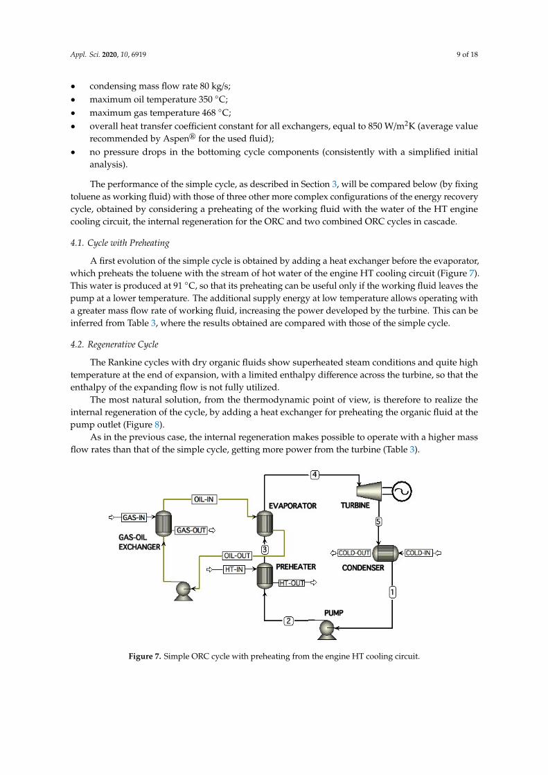
4.1. Cycle with Preheating
A first evolution of the simple cycle is obtained by adding a heat exchanger before the evaporator,which preheats the toluene with the stream of hot water of the engine HT cooling circuit (Figure 7).This water is produced at 91 C, so that its preheating can be useful only if the working fluid leaves thepump at a lower temperature. The additional supply energy at low temperature allows operating witha greater mass flow rate of working fluid, increasing the power developed by the turbine. This can beinferred from Table 3, where the results obtained are compared with those of the simple cycle.
4.2. Regenerative Cycle
The Rankine cycles with dry organic fluids show superheated steam conditions and quite hightemperature at the end of expansion, with a limited enthalpy difference across the turbine, so that theenthalpy of the expanding flow is not fully utilized.
The most natural solution, from the thermodynamic point of view, is therefore to realize theinternal regeneration of the cycle, by adding a heat exchanger for preheating the organic fluid at thepump outlet (Figure 8).
As in the previous case, the internal regeneration makes possible to operate with a higher massflow rates than that of the simple cycle, getting more power from the turbine (Table 3).
Appl. Sci. 2020, 10, x FOR PEER REVIEW 9 of 18
• maximum oil temperature 350 °C; • maximum gas temperature 468 °C; • overall heat transfer coefficient constant for all exchangers, equal to 850 W/m2K (average value
recommended by Aspen® for the used fluid); • no pressure drops in the bottoming cycle components (consistently with a simplified initial
analysis).
The performance of the simple cycle, as described in Section 3, will be compared below (by fixing toluene as working fluid) with those of three other more complex configurations of the energy recovery cycle, obtained by considering a preheating of the working fluid with the water of the HT engine cooling circuit, the internal regeneration for the ORC and two combined ORC cycles in cascade.
4.1. Cycle with Preheating
A first evolution of the simple cycle is obtained by adding a heat exchanger before the evaporator, which preheats the toluene with the stream of hot water of the engine HT cooling circuit (Figure 7). This water is produced at 91 °C, so that its preheating can be useful only if the working fluid leaves the pump at a lower temperature. The additional supply energy at low temperature allows operating with a greater mass flow rate of working fluid, increasing the power developed by the turbine. This can be inferred from Table 3, where the results obtained are compared with those of the simple cycle.
4.2. Regenerative Cycle
The Rankine cycles with dry organic fluids show superheated steam conditions and quite high temperature at the end of expansion, with a limited enthalpy difference across the turbine, so that the enthalpy of the expanding flow is not fully utilized.
The most natural solution, from the thermodynamic point of view, is therefore to realize the internal regeneration of the cycle, by adding a heat exchanger for preheating the organic fluid at the pump outlet (Figure 8).
As in the previous case, the internal regeneration makes possible to operate with a higher mass flow rates than that of the simple cycle, getting more power from the turbine (Table 3).
Figure 7. Simple ORC cycle with preheating from the engine HT cooling circuit. Figure 7. Simple ORC cycle with preheating from the engine HT cooling circuit.

Appl. Sci. 2020, 10, 6919 10 of 18Appl. Sci. 2020, 10, x FOR PEER REVIEW 10 of 18
Figure 8. Regenerated ORC cycle.
4.3. Two Combined ORC with Different Temperature Levels
Let’s finally consider two combined cycles, operating with different organic fluids at two different thermal levels (Figure 9). The cycle at higher temperature (toluene) is coupled to the exhaust gas through the thermal oil circuit, as in the ORCs previously shown; the lower temperature cycle (using isobutene as working fluid) receives energy directly from the HT cooling water circuit of the ICE.
Figure 9. Combined ORC cycles with two temperature levels.
As mentioned before, the flow in the HT cooling circuit is adjusted to maintain a constant return temperature to the engine. In case water in the HT cooling circuit is used for the evaporation of the isobutene, the return temperature of the HT water circuit must not drop below the value set in the engine-control system. To avoid this eventuality and to enable the combined cycles to operate with the highest possible flow in the evaporator, an exhaust gas/water recuperator has been introduced to rise the temperature of the water leaving the recovery system (Figure 9), assuming that the gas at the
Figure 8. Regenerated ORC cycle.
4.3. Two Combined ORC with Different Temperature Levels
Let’s finally consider two combined cycles, operating with different organic fluids at two differentthermal levels (Figure 9). The cycle at higher temperature (toluene) is coupled to the exhaust gasthrough the thermal oil circuit, as in the ORCs previously shown; the lower temperature cycle (usingisobutene as working fluid) receives energy directly from the HT cooling water circuit of the ICE.
Appl. Sci. 2020, 10, x FOR PEER REVIEW 10 of 18
Figure 8. Regenerated ORC cycle.
4.3. Two Combined ORC with Different Temperature Levels
Let’s finally consider two combined cycles, operating with different organic fluids at two different thermal levels (Figure 9). The cycle at higher temperature (toluene) is coupled to the exhaust gas through the thermal oil circuit, as in the ORCs previously shown; the lower temperature cycle (using isobutene as working fluid) receives energy directly from the HT cooling water circuit of the ICE.
Figure 9. Combined ORC cycles with two temperature levels.
As mentioned before, the flow in the HT cooling circuit is adjusted to maintain a constant return temperature to the engine. In case water in the HT cooling circuit is used for the evaporation of the isobutene, the return temperature of the HT water circuit must not drop below the value set in the engine-control system. To avoid this eventuality and to enable the combined cycles to operate with the highest possible flow in the evaporator, an exhaust gas/water recuperator has been introduced to rise the temperature of the water leaving the recovery system (Figure 9), assuming that the gas at the
Figure 9. Combined ORC cycles with two temperature levels.
As mentioned before, the flow in the HT cooling circuit is adjusted to maintain a constant returntemperature to the engine. In case water in the HT cooling circuit is used for the evaporation of theisobutene, the return temperature of the HT water circuit must not drop below the value set in theengine-control system. To avoid this eventuality and to enable the combined cycles to operate withthe highest possible flow in the evaporator, an exhaust gas/water recuperator has been introduced torise the temperature of the water leaving the recovery system (Figure 9), assuming that the gas at the

Appl. Sci. 2020, 10, 6919 11 of 18
chimney has not to be cooled below 140 C. In few words, the heat exchanger “HT WHR (optional)” inFigure 2 is replaced by the “Evaporator I-butane” and the “Recuperator Gas-Water” in Figure 9.
The two cycles exchange energy also each other. To take advantage from the high temperature oftoluene vapor exiting the turbine, an additional heat exchanger is introduced for superheating theisobutene, allowing the lower temperature cycle to increase its power output (Table 3).
Table 3. Performance comparison of different configurations of the ORC bottom cycle.
Engine Load [%]100 85 75 50 25
Simple cyclePower [kW] 592 541 523 410 227
η [%] 23.2 22.8 22.9 23 22.9
Pre-heated cyclePower [kW] 671 637 620 484 280
η [%] 23.7 23.7 23.9 23.9 21.9
Regenerating cyclePower [kW] 684 639 622 488 288
η [%] 26.7 26.7 26.8 26.8 26.7
Cascade cyclePower [kW] 706 652 608 459 275
η (toluene) [%] 20.8 20.4 19.6 19.2 19η (isobutene) [%] 10 10.2 10 10.2 10
4.4. Performance Comparison of Different Configurations
The total power obtainable by combining the propulsion ICE and the ORC system is shown inFigure 10, for different engine loads and the considered configurations of the bottom cycle.
Appl. Sci. 2020, 10, x FOR PEER REVIEW 11 of 18
chimney has not to be cooled below 140 °C. In few words, the heat exchanger “HT WHR (optional)” in Figure 2 is replaced by the “Evaporator I-butane” and the “Recuperator Gas-Water” in Figure 9.
The two cycles exchange energy also each other. To take advantage from the high temperature of toluene vapor exiting the turbine, an additional heat exchanger is introduced for superheating the isobutene, allowing the lower temperature cycle to increase its power output (Table 3).
Table 3. Performance comparison of different configurations of the ORC bottom cycle.
Engine Load [%] 100 85 75 50 25
Simple cycle Power [kW] 592 541 523 410 227 η [%] 23.2 22.8 22.9 23 22.9
Pre-heated cycle Power [kW] 671 637 620 484 280 η [%] 23.7 23.7 23.9 23.9 21.9
Regenerating cycle Power [kW] 684 639 622 488 288 η [%] 26.7 26.7 26.8 26.8 26.7
Cascade cycle Power [kW] 706 652 608 459 275 η (toluene) [%] 20.8 20.4 19.6 19.2 19 η (isobutene) [%] 10 10.2 10 10.2 10
4.4. Performance Comparison of Different Configurations
The total power obtainable by combining the propulsion ICE and the ORC system is shown in Figure 10, for different engine loads and the considered configurations of the bottom cycle.
Figure 10. Power of the combined propulsion system, according to the load, for the different cycle configurations studied.
A significant power gain (about 10%) is already achieved with the simple cycle. For the other configurations the increase is slightly higher, at least with reference to the full load of the engine. The
Figure 10. Power of the combined propulsion system, according to the load, for the different cycleconfigurations studied.

Appl. Sci. 2020, 10, 6919 12 of 18
A significant power gain (about 10%) is already achieved with the simple cycle. For the otherconfigurations the increase is slightly higher, at least with reference to the full load of the engine.The corresponding efficiencies are reported in Figure 11, showing that they grow (up to 8 points) withdecreasing engine load. In fact, if the engine efficiency reduces, a bigger fraction of the energy of thefuel input is available as waste heat for the bottom cycle.
Appl. Sci. 2020, 10, x FOR PEER REVIEW 12 of 18
corresponding efficiencies are reported in Figure 11, showing that they grow (up to 8 points) with decreasing engine load. In fact, if the engine efficiency reduces, a bigger fraction of the energy of the fuel input is available as waste heat for the bottom cycle.
Figure 11. Increase in percentage points of the combined propulsion system efficiency, according to the load, for the different cycle configurations studied.
The regenerated and the two combined cycles show the bigger efficiency increase, but the latter is affected by the temperature decrease in the HT cooling circuit at low engine loads. Therefore, it can be inferred that the regenerated cycle gives the best performance, without excessive plant complexity. Then, the following design analysis has been carried out on this plant configuration and the sizing and the realistic off-design performance of the required heat exchangers have been obtained.
5. Sizing of the Heat Exchangers for the ORC Regenerated Cycle
The specific design of shell and tube heat exchangers has been performed by using the software Aspen Tasc®, to address in detail the performance of the regenerative cycle and to perform the economic analysis of the investment. The used software incorporates an extensive library of organic fluids and therefore it has been possible to define in detail the geometry of heat exchangers, according to the prescriptions of the Tubular Exchanger Manufacturers Association (TEMA) [44], and to calculate accurately the phase transition and the pressure drop in the shell and in the tubes
The heat exchangers in the regenerated cycle are the exhaust gas/thermal oil heat exchanger, the evaporator, the regenerator and the condenser (Figure 8). During sizing and geometry selection, it has been paid attention to limit the size, in view of a possible installation in a room next to the engine room. The main data obtained for the different heat exchangers are summarized in Table 4.
To ensure the proper operation of the engine, the pressure drop of the gas stream through the exhaust gas circuit must be below 3 kPa [4], therefore the maximum loss through the exhaust gas/thermal oil heat exchanger has been set to 1.2 kPa. In this way, an acceptable backpressure is guaranteed for the engine turbocharger, which is just upstream this heat exchanger.
The exhaust gas/thermal oil heat exchanger is a vertical tube bundle (containing the thermal oil), with the direct flow of gases in the shell without support baffles, for reducing losses.
For the evaporator it was used a shell and tube heat exchanger, with geometry type CFU (channel Integral with tube-sheet, Two-pass shell with longitudinal baffle, U-tube bundle [44]) and two shells in parallel. Taking the toluene pressure (20 bar), it is better to locate it inside the tubes [45], while the flow of hot thermal oil circulates outside. The losses are not a limit for this heat exchanger, as a sensitivity analysis has shown that fluctuations in the maximum cycle pressure of about few bars lead to negligible power losses. The pinch-point obtained in the oil/toluene exchanger is equal to 5.3 °C, a value that demonstrates a high heat transfer efficiency.
Figure 11. Increase in percentage points of the combined propulsion system efficiency, according to theload, for the different cycle configurations studied.
The regenerated and the two combined cycles show the bigger efficiency increase, but the latter isaffected by the temperature decrease in the HT cooling circuit at low engine loads. Therefore, it can beinferred that the regenerated cycle gives the best performance, without excessive plant complexity.Then, the following design analysis has been carried out on this plant configuration and the sizing andthe realistic off-design performance of the required heat exchangers have been obtained.
5. Sizing of the Heat Exchangers for the ORC Regenerated Cycle
The specific design of shell and tube heat exchangers has been performed by using the softwareAspen Tasc®, to address in detail the performance of the regenerative cycle and to perform theeconomic analysis of the investment. The used software incorporates an extensive library of organicfluids and therefore it has been possible to define in detail the geometry of heat exchangers, accordingto the prescriptions of the Tubular Exchanger Manufacturers Association (TEMA) [44], and to calculateaccurately the phase transition and the pressure drop in the shell and in the tubes
The heat exchangers in the regenerated cycle are the exhaust gas/thermal oil heat exchanger,the evaporator, the regenerator and the condenser (Figure 8). During sizing and geometry selection,it has been paid attention to limit the size, in view of a possible installation in a room next to the engineroom. The main data obtained for the different heat exchangers are summarized in Table 4.
To ensure the proper operation of the engine, the pressure drop of the gas stream throughthe exhaust gas circuit must be below 3 kPa [4], therefore the maximum loss through the exhaustgas/thermal oil heat exchanger has been set to 1.2 kPa. In this way, an acceptable backpressure isguaranteed for the engine turbocharger, which is just upstream this heat exchanger.
The exhaust gas/thermal oil heat exchanger is a vertical tube bundle (containing the thermal oil),with the direct flow of gases in the shell without support baffles, for reducing losses.
For the evaporator it was used a shell and tube heat exchanger, with geometry type CFU (channelIntegral with tube-sheet, Two-pass shell with longitudinal baffle, U-tube bundle [44]) and two shells inparallel. Taking the toluene pressure (20 bar), it is better to locate it inside the tubes [45], while the flow
Appl. Sci. 2020, 10, 6919 13 of 18
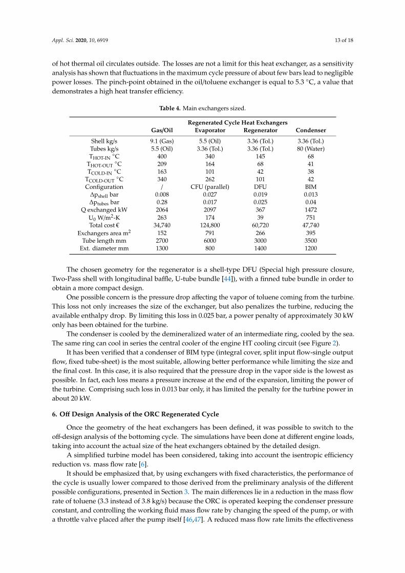
of hot thermal oil circulates outside. The losses are not a limit for this heat exchanger, as a sensitivityanalysis has shown that fluctuations in the maximum cycle pressure of about few bars lead to negligiblepower losses. The pinch-point obtained in the oil/toluene exchanger is equal to 5.3 C, a value thatdemonstrates a high heat transfer efficiency.
Table 4. Main exchangers sized.
Regenerated Cycle Heat ExchangersGas/Oil Evaporator Regenerator Condenser
Shell kg/s 9.1 (Gas) 5.5 (Oil) 3.36 (Tol.) 3.36 (Tol.)Tubes kg/s 5.5 (Oil) 3.36 (Tol.) 3.36 (Tol.) 80 (Water)THOT-IN
C 400 340 145 68THOT-OUT
C 209 164 68 41TCOLD-IN
C 163 101 42 38TCOLD-OUT
C 340 262 101 42Configuration / CFU (parallel) DFU BIM
∆pshell bar 0.008 0.027 0.019 0.013∆ptubes bar 0.28 0.017 0.025 0.04
Q exchanged kW 2064 2097 367 1472U0 W/m2-K 263 174 39 751Total cost € 34,740 124,800 60,720 47,740
Exchangers area m2 152 791 266 395Tube length mm 2700 6000 3000 3500
Ext. diameter mm 1300 800 1400 1200
The chosen geometry for the regenerator is a shell-type DFU (Special high pressure closure,Two-Pass shell with longitudinal baffle, U-tube bundle [44]), with a finned tube bundle in order toobtain a more compact design.
One possible concern is the pressure drop affecting the vapor of toluene coming from the turbine.This loss not only increases the size of the exchanger, but also penalizes the turbine, reducing theavailable enthalpy drop. By limiting this loss in 0.025 bar, a power penalty of approximately 30 kWonly has been obtained for the turbine.
The condenser is cooled by the demineralized water of an intermediate ring, cooled by the sea.The same ring can cool in series the central cooler of the engine HT cooling circuit (see Figure 2).
It has been verified that a condenser of BIM type (integral cover, split input flow-single outputflow, fixed tube-sheet) is the most suitable, allowing better performance while limiting the size andthe final cost. In this case, it is also required that the pressure drop in the vapor side is the lowest aspossible. In fact, each loss means a pressure increase at the end of the expansion, limiting the power ofthe turbine. Comprising such loss in 0.013 bar only, it has limited the penalty for the turbine power inabout 20 kW.
6. Off Design Analysis of the ORC Regenerated Cycle
Once the geometry of the heat exchangers has been defined, it was possible to switch to theoff-design analysis of the bottoming cycle. The simulations have been done at different engine loads,taking into account the actual size of the heat exchangers obtained by the detailed design.
A simplified turbine model has been considered, taking into account the isentropic efficiencyreduction vs. mass flow rate [6].
It should be emphasized that, by using exchangers with fixed characteristics, the performance ofthe cycle is usually lower compared to those derived from the preliminary analysis of the differentpossible configurations, presented in Section 3. The main differences lie in a reduction in the mass flowrate of toluene (3.3 instead of 3.8 kg/s) because the ORC is operated keeping the condenser pressureconstant, and controlling the working fluid mass flow rate by changing the speed of the pump, or witha throttle valve placed after the pump itself [46,47]. A reduced mass flow rate limits the effectiveness

Appl. Sci. 2020, 10, 6919 14 of 18
of the heat exchangers, therefore, superheated conditions may not be always reached at turbine inlet.Furthermore, the pressure losses in the heat exchangers reduce the turbine enthalpy drop, with aconsequent lower power of about 50 kW at maximum load. Finally, the heat transfer coefficientscalculated through the libraries of Aspen Tasc® have been almost always lower than the default valueused in Aspen Plus®, increasing the area of heat exchangers. This last aspect significantly affects theircosts and overall dimensions.
The actual performance obtained by the bottom regenerative Rankine cycle is presented in Table 5.The gross power gain reaches 520 kW and it is constant for medium and high engine loads, until theorganic fluid flow rate can be kept constant. Knowing the real off-design performances of the energyrecovery system, it is possible to calculate the real power of the combined engine and ORC system ateach load, in order to evaluate the annual achievable fuel saving.
By considering the engine average operation duty equal to 6960 h per year, the fuel saved can becalculated taking the engine load distribution into account, like in [48,49]:
• 100% load is typically used 1.5% of the time for maximum operating speed;• 85% load is used to obtain the cruising speed, with the minimum specific consumption of the
engine, and is usually kept for 85% of the time;• 75% load is used for 5% of the time;• 50% load is used in ancillary services, when the ship stops in port, for 7% of the time;• 25% load is used for 1.5% of the time in port operation.
Table 5. Main characteristics for the regenerated ORC cycle in off-design analysis.
Engine Load % 100 85 75 50 25
PORC gross kW 520 520 520 374 174PORCnet kW 480 480 480 340 150ηORC % 25.7 25.7 25.7 22.5 19.2Tgas
C 400 420 438 468 443Toil
C 340 340 340 340 340Tvap
C 262 262 262 262 262pmax bar 20 20 20 20 20pcond bar 0.12 0.12 0.12 0.12 0.12
∆pregen bar 0.025 0.025 0.025 0.008 0.003∆pcond bar 0.013 0.013 0.013 0.011 0.006
Moil kg/s 5.5 5.5 5.5 4.5 2.5Mtol kg/s 3.36 3.36 3.36 2.76 1.5ηis-turb % 80 80 80 70 60
Table 6 lists the data obtained for both conventional and combined engine, assuming the LHVof LNG fuel equivalent to 36 MJ/Nm3 and the price of natural gas of 12 $/Mbtu on the basis of theEuropean average price 2011–2015 [50]. In the calculations the cost of owning and maintaining thepropulsion system has been evaluated as 10% of fuel cost, obtaining a final cost of 0.32 €/Nm3 for theLNG. It can be appreciated how the ORC gives a significant contribution to fuel savings at the mostfrequent load used during a year (85% of maximum load).

Appl. Sci. 2020, 10, 6919 15 of 18
Table 6. Annual savings of the naval ICE with the bottom ORC.
Load Engine +ORC Power
CONSUMPTIONSFuel Saved Saving Per Year
Specific Engine Engine + ORC
% kW kJ/kWh Nm3/h Nm3/h Nm3/h €
100 6180 7220 1143 1047 96 321685 5325 7400 996 897 99 186,78875 4755 7420 881 782 99 11,01750 3190 7890 625 550 75 11,61325 1575 7900 313 280 33 1100
TOT 213,733
7. Economic and Environmental Remarks
A first approximation of the installation cost of a ORC group can be evaluated as the sum ofturbine, pumps, exchangers and fluids costs. The costs of the heat transfer components have beenobtained by means of Aspen Tasc®:
• Gas/oil heat exchanger 130,000 €;• evaporator 190,000 €;• regenerator 95,000 €;• condenser 100,000 €.
For the other components, the following economic estimates have been considered on the basis ofinformation from manufacturers:
• turbine 150,000 €;• electric generator 30,000 €• toluene pump 20,000 €;• thermal oil pump 10,000 €;• toluene 30,000 €;• diathermic oil 15,000 €;• balance of the plant (piping, filters, valves, etc.) 115,500 €.
The expected total cost for the bottom regenerated cycle could be obtained adding to the sum ofall these terms (€885,000) a mark-up of 20%, resulting in a total price of 1,062,600 €.
Taking into account the estimation of actual fuel saving for the typical operating year, a simplepayback period of the investment equal to 4.9 years has been obtained, while considering a discountrate equal to 3% a dynamic payback period of the investment equal to 5.9 years has been obtained.
The recovery of waste heat downstream of the propulsion engine by means of a bottom ORC hasalso a good cost/performance ratio, equal to 2214 €/kW.
The adoption of an ORC group as a supplement of the propulsion system, allows saving largeamounts of LNG fuel, implying a reduction in atmospheric emissions of pollutant agents, such ascarbon dioxide and nitrogen oxides.
To evaluate the quantity of CO2 avoided, the specific average amount of CO2 emitted by theWärtsilä 6L50DF engine, equal to 430 g/kWh, can be considered. By applying this value to the averagepower produced by the ORC, and on the basis of the hours of use per year of the propulsion system,1380 ton/year of CO2 non emitted into the atmosphere can be obtained.
Not emitted into the atmosphere NOx tons can be derived in the same way. Starting from theengine average emission of 2.5 g/kWh, a total amount equal to 8.4 ton/year of avoided NOx emissionhas been obtained.

Appl. Sci. 2020, 10, 6919 16 of 18
8. Conclusions
In the present study various options of energy recovery from an ICE for ship propulsion, by addingbottom ORCs, have been examined. The analysis is based on the real operating data of a marine engine,considering the needs of its cooling system, and on the use of a realistic design/off-design simulatorof the heat exchangers, available in Aspen®. In this way, realistic values of the actual performanceincrease of the propulsion system have been obtained.
Different possible bottom ORC configurations are simulated, and different working fluids are takeninto account, jointly with regenerative and two-temperature levels designs, allowing the identificationof the most suitable ORC configuration for reducing the fuel consumption of the propulsion systemduring its operation.
The main results of the study allow to conclude that Toluene confirm the well-match with theengine exhaust gases heat source, even if an intermediate circuit of thermal oil has to be added betweenexhaust gas and Toluene, because of its high flammability. On the other hand, Isobutene is better suitedto be coupled with the HT circuit at about 90 C and can be used, jointly with Toluene, in a doublelevel bottom ORC. A regenerated cycle bottom ORC is expected to obtain a power increment of about10%. In the case study, an additional power of 520 kW has been obtained.
A robust preliminary economic evaluation of the real operation of the ship engine has beenperformed on the basis of the recovered energy flows, showing a payback time equal to about6 years, thanks to the fuel savings obtained as a result of greater efficiency. Finally, the ORC bringsinteresting benefits in terms of reducing atmospheric pollutant emissions of both carbon dioxide andnitrogen oxide.
Author Contributions: Conceptualization, M.R. and P.P.; methodology, M.R. and P.P.; software, M.R.; validation,M.C., M.R. and P.P.; formal analysis, M.C.; investigation, M.R.; resources, P.P.; data curation, M.R.; writing—originaldraft preparation, M.R. and P.P.; writing—review and editing, M.C.; supervision, M.C. All authors have read andagreed to the published version of the manuscript.
Funding: This research received no external funding.
Acknowledgments: The Authors would like to thank J. Bonafin and P. Tremuli for the help in performing thenumerical simulations and in gathering economic and environmental data.
Conflicts of Interest: The authors declare no conflict of interest.
References
1. Marpol 73/78 Annex VI. Regulations for the Prevention of Air Pollution from Ships; International MaritimeOrganization: London, UK, 2005.
2. Register, L. LNG-Fuelled Deep Sea Shipping; Lloyds Register: London, UK, 2012.3. Banawan, A.A.; El Gohary, M.M.; Sadek, I.S. Environmental and economical benefits of changing from
marine diesel oil to natural-gas fuel for short-voyage high-power passenger ships. Proc. Inst. Mech. Eng.Part M J. Eng. Marit. Environ. 2010, 224, 103–113. [CrossRef]
4. Burel, F.; Taccani, R.; Zuliani, N. Improving sustainability of maritime transport through utilization ofLiquefied Natural Gas (LNG) for propulsion. Energy 2013, 57, 412–420. [CrossRef]
5. Wärtsilä Finland Oy. 50DF Product Guide; Wärtsilä Finland Oy: Helsinky, Finland, 2019.6. Saidur, R.; Muzammil, W.K.; Hassan, M.H.; Paria, S.; Hasanuzzaman, M. Technologies to recover exhaust
heat from internal combustion engines. Renew. Sustain. Energy Rev. 2012, 16, 5649–5659. [CrossRef]7. Gequn, S.; Youcai, L.; Haiqiao, W.; Hua, T.; Jian, Z.; Lina, L. A review of waste heat recovery on two-stroke
IC engine aboard ships. Renew. Sustain. Energy Rev. 2013, 19, 385–401.8. Grljušic, M.; Medica, V.; Racic, N. Thermodynamic Analysis of a Ship Power Plant Operating with Waste
Heat Recovery through Combined Heat and Power Production. Energies 2014, 7, 7368–7394. [CrossRef]9. Grljušic, M.; Medica, V.; Racic, N. Calculation of Efficiencies of a Ship Power Plant Operating with Waste
Heat Recovery through Combined Heat and Power Production. Energies 2015, 8, 4273–4299. [CrossRef]10. Bellolio, S.; Lemort, V.; Rigo, P. Organic Rankine Cycle Systems for Waste Heat Recovery in Marine Applications;
University of Liège: Liège, Belgium, 2015.

Appl. Sci. 2020, 10, 6919 17 of 18
11. El Geneidy, R.; Otto, K.; Ahtila, P.; Kujala, P.; Sillanpää, K.; Mäki-Jouppila, T. Increasing energy efficiency inpassenger ships by novel energy conservation measures. J. Mar. Eng. Technol. 2018, 17, 85–98. [CrossRef]
12. Andreasen, G.J.; Meroni, A.; Haglind, F. A Comparison of Organic and Steam Rankine Cycle Power Systemsfor Waste Heat Recovery on Large Ships. Energies 2017, 10, 547. [CrossRef]
13. Larsen, U.; Sigthorsson, O.; Haglind, F. A comparison of advanced heat recovery power cycles in a combinedcycle for large ships. Energy 2014, 74, 260–268. [CrossRef]
14. Casisi, M.; Costanzo, S.; Pinamonti, P.; Reini, M. Two-level evolutionary multi-objective optimization of adistrict heating system with distributed cogeneration. Energies 2019, 12, 114. [CrossRef]
15. Desideri, U.; Bidini, G. Study of Possible Criteria for Optimization Geothermal Power Plants. Energy Convers.Manag. 1997, 38, 1681–1691. [CrossRef]
16. Hung, T.C.; Shai, T.Y.; Wang, S.K. A Review of Organic Rankine Cycles (ORCs) for the Recovery of Low-GradeWaste Heat. Energy 1997, 22, 661–667. [CrossRef]
17. Schuster, A.; Karellas, S.; Kakaras, E.; Spliethoff, H. Energetic and economic investigation of Organic RankineCycle applications. Appl. Therm. Eng. 2009, 29, 1809–1817. [CrossRef]
18. Duvia, A.; Guercio, A.; Rossi, C. Technical and economic aspects of Biomass fulled CHP plants based on ORCturbogenerators feeding existing district heating networks. In Proceedings of the 17th European BiomassConference, Hamburg, Germany, 29 June–3 July 2009.
19. Vaja, I.; Gambarotta, A. Internal combustion engine (ICE) bottoming with Organic Rankine bottoming cycles(ORCs). Energy 2010, 35, 1084–1093. [CrossRef]
20. Song, S.; Zhang, H.; Lou, Z.; Yang, F.; Yang, K.; Wang, H.; Bei, C.; Chang, Y.; Yao, B. Performance analysis ofexhaust waste heat recovery system for stationary CNG engine based on organic Rankine cycle. Appl. Therm.Eng. 2015, 76, 301–309. [CrossRef]
21. Bombarda, P.; Invernizzi, M.C.; Pietra, C. Heat recovery from Diesel engines: A thermodynamic comparisonbetween Kalina and ORC cycles. Appl. Therm. Eng. 2010, 30, 212–219. [CrossRef]
22. Chun, W.; Tam, I.C.K.; Wu, D. Thermo-Economic Performance of an Organic Rankine Cycle SystemRecovering Waste Heat Onboard an Offshore Service Vessel. J. Mar. Sci. Eng. 2020, 8, 351. [CrossRef]
23. Konur, O.; Saatcioglu, O.Y.; Korkmaz, S.A.; Erdogan, A.; Colpan, C.O. Heat exchanger network design of anorganic Rankine cycle integrated waste heat recovery system of a marine vessel using pinch point analysis.Int. J. Energy Res. 2020, 1–17. [CrossRef]
24. Yang, M.H.; Yeh, R.H. Thermodynamic and economic performances optimization of an organic Rankinecycle system utilizing exhaust gas of a large marine diesel engine. Appl. Energy 2015, 149, 1–12. [CrossRef]
25. Girgin, I.; Ezgi, C. Design and thermodynamic and thermoeconomic analysis of an organic Rankine cycle fornaval surface ship applications. Energy Convers. Manag. 2017, 148, 623–634. [CrossRef]
26. Uusitalo, A.; Nerg, J.; Nikkanen, S.; Elg, M. Numerical analysis on utilizing excess steam for electricityproduction in cruise ships. J. Clean. Prod. 2019, 209, 424–438. [CrossRef]
27. Liang, Y.; Shu, G.; Tian, H.; Wei, H.; Liang, X.; Liu, L.; Wang, X. Theoretical analysis of a novelelectricity–cooling cogeneration system(ECCS) based on cascade use of waste heat of marine engine.Energy Convers. Manag. 2014, 85, 888–894. [CrossRef]
28. Gnes, P.; Pinamonti, P.; Reini, M. Bi-level optimization of the energy recovery system from the InternalCombustion Engines of a cruise ship. Appl. Sci. 2020. to be published on.
29. Aspen Physical Property System. Version 8.4. November 2013. Available online: http://profsite.um.ac.ir/~fanaei/_private/Property%20Methods%208_4.pdf (accessed on 1 June 2019).
30. Angelino, G.; Colonna di Paliano, P. Multicomponent Working Fluids for Organic Rankine Cycles (ORCs).Energy 1998, 23, 449–463. [CrossRef]
31. Saleh, B.; Koglbauer, G.; Wendland, M.; Fischer, J. Working fluids for low-temperature organic Rankinecycles. Energy 2007, 32, 1210–1221. [CrossRef]
32. Angelino, G.; Invernizzi, C. Cyclic Methyl-siloxanes as Working Fluids for Space Power Cycles. Trans. ASMEJ. Sol. Energy Eng. 1993, 115, 130–137. [CrossRef]
33. Ge, Z.; Li, J.; Duan, Y.; Yang, Z.; Xie, Z. Thermodynamic Performance Analyses and Optimization ofDual-Loop Organic Rankine Cycles for Internal Combustion Engine Waste Heat Recovery. Appl. Sci. 2019, 9,680. [CrossRef]
34. Lai, N.A.; Wendland, M.; Fischer, J. Working fluids for high-temperature organic Rankine cycles. Energy2011, 36, 199–211. [CrossRef]

Appl. Sci. 2020, 10, 6919 18 of 18
35. Bruno, J.C.; López-Villada, J.; Letelier, E.; Romera, S.; Coronas, A. Modeling and optimization of solar organicRankine cycle engines for reverse osmosis desalination. Appl. Therm. Eng. 2008, 28, 2212–2226. [CrossRef]
36. Micheli, D.; Pinamonti, P.; Reini, M.; Taccani, R. Performance Analysis and Working Fluid Optimization of aCogenerative Organig Rankine Cycle (ORC) Plant. J. Energy Resour. Technol. 2013, 135, 021601. [CrossRef]
37. Gequn, S.; Yuanyuan, G.; Hua, T.; Wei, H.; Liang, X. Study of mixtures based on hydrocarbons used in ORC(Organic Rankine Cycle) for engine waste heat recovery. Energy 2014, 74, 428–438.
38. Gequn, S.; Xiaoning, L.; Hua, T.; Liang, X.; Wei, H.; Wang, X. Alkanes as working fluids for high-temperatureexhaust heat recovery of diesel engine using organic Rankine cycle. Appl. Energy 2014, 119, 204–217.
39. Hua, T.; Gequn, S.; Wei, H.; Liang, X.; Liu, L. Fluids and parameters optimization for the organic Rankinecycles (ORCs) used in exhaust heat recovery of Internal Combustion Engine (ICE). Energy 2012, 47, 125–136.
40. Dow Technical Report. Available online: http://www.dow.com/heattrans/products/synthetic/dowtherm.htm(accessed on 1 June 2019).
41. Junjiang, B.; Li, Z. A review of working fluid and expander selections for organic Rankine cycle. Renew.Sustain. Energy Rev. 2013, 24, 325–342.
42. Prabhu, E. Solar Trough Organic Rankine Electricity System (STORES)-Stage 1 Power Plant Optimization andEconomics; Technical Report No. NREL/SR-550-39433; National Renewable Energy Laboratory: Golden, CO,USA, March 2006.
43. Dai, Y.; Wang, J.; Gao, L. Parametric optimization and comparative study of organic Rankine cycle (ORC)forlow grade waste heat recovery. Energy Convers. Manag. 2009, 50, 576–582. [CrossRef]
44. TEMA Tubular Exchanger Manufacturers Association. Available online: http://www.tema.org/ (accessed on1 July 2019).
45. Serth, R.W. Process Heat Transfer Principles and Applications; Elsevier Science and Technology Books:Amsterdam, The Netherlands, 2007.
46. Mondejar, M.E.; Ahlgren, F.; Thern, M.; Genrup, M. Quasi-steady state simulation of an organic Rankinecycle for waste heat recovery in a passenger vessel. Appl. Energy 2017, 185, 1324–1335. [CrossRef]
47. Ahlgren, F.; Mondejar, M.E.; Genrup, M.; Thern, M. Waste heat recovery in a cruise vessel in the Baltic Sea byusing an organic Rankine cycle: A case study. J. Eng. Gas Turbines Power 2016, 138, 011702. [CrossRef]
48. Shu, G.; Liu, P.; Tian, H.; Wang, X.; Jing, D. Operational profile based thermal-economic analysis on anOrganic Rankine cycle using for harvesting marine engine’s exhaust waste heat. Energy Convers. Manag.2017, 146, 107–123. [CrossRef]
49. Baldi, F.; Larsen, U.; Gabrieli, C. Comparison of different procedures for the optimisation of a combinedDiesel engine and organic Rankine cycle system based on ship operational profile. Ocean. Eng. 2015, 110,85–93. [CrossRef]
50. Ref-e. Economics Engineering Energy Environment-Working Paper n. 12; Ref-e: Milan, Italy, July 2015.
© 2020 by the authors. Licensee MDPI, Basel, Switzerland. This article is an open accessarticle distributed under the terms and conditions of the Creative Commons Attribution(CC BY) license (http://creativecommons.org/licenses/by/4.0/).