including the new low loss “a”version · product reference ec1-50-hf ec2-50-hf ec4-50-hf...
TRANSCRIPT

Including the
New LOW LOSS “A” Version
Edition November 2008

2 Kabelwerk Eupen AG
The foundation of the cable factoryKABELWERK EUPEN AG as manufac-turer of electrical cables goes back to thebeginning of this century. Today the com-pany has a staff of 950 people producingpower cables, telecommunication cablesand RF-Cables.
Since broadband transmission becamepossible, KABELWERK EUPEN AG hasbeen involved in the design and manu-facture of coaxial cables.The introduction of Cable Television in1962 was decisive for the start of produc-ing coaxial cables on a larger scale.With the increasing demand for coaxialcables and the intensive R&D to improvecable construction and transmissioncharacteristics, KABELWERK EUPENAG has become today one of the lead-ing manufacturer for coaxial cables inthe World.
Over 45 years of experience in the fieldof RF-Cables, the company constantlydeveloped its extensive manufacturingprocess bearing in mind the improvementof quality.
In 1999 KABELWERK EUPEN AG devel-oped a new generation of coaxial cableconnectors.
Since 1993 the company is ISO 9001certified for all its products.
Today the cables and connectors fromKABELWERK EUPEN AG, together is anunbeatable match to guarantee superiorperformances and long service life.

Kabelwerk Eupen AG 3
Contents
Introduction
Introduction to EC3 cables and connectors. . . . . . . . . . . . . . . . . . . . . . . . . . . . . . . . . . . . . . . 4
Coaxial cables, connectors,
tools & grounding clamps
EC3 Foam Dielectric . . . . . . . . . . . . . . . . . . . . . . . . . . . . . . . . . 61/4” Hiflex . . . . . . . . . . . . . . . . . . . . . . . . . . . . . . . . . . . . . . . . . . . 101/2” Hiflex . . . . . . . . . . . . . . . . . . . . . . . . . . . . . . . . . . . . . . . . . . . 127/8” Hiflex . . . . . . . . . . . . . . . . . . . . . . . . . . . . . . . . . . . . . . . . . . . 141-1/4” Hiflex . . . . . . . . . . . . . . . . . . . . . . . . . . . . . . . . . . . . . . . . . 161/4” . . . . . . . . . . . . . . . . . . . . . . . . . . . . . . . . . . . . . . . . . . . . . . . . . . 181/2” . . . . . . . . . . . . . . . . . . . . . . . . . . . . . . . . . . . . . . . . . . . . . . . . . . 207/8”A . . . . . . . . . . . . . . . . . . . . . . . . . . . . . . . . . . . . . . . . . . . . . . . . . 221-1/4”A. . . . . . . . . . . . . . . . . . . . . . . . . . . . . . . . . . . . . . . . . . . . . . . 241-5/8”A. . . . . . . . . . . . . . . . . . . . . . . . . . . . . . . . . . . . . . . . . . . . . . . 262-1/4” . . . . . . . . . . . . . . . . . . . . . . . . . . . . . . . . . . . . . . . . . . . . . . . . 28
Jumper cables
. . . . . . . . . . . . . . . . . . . . . . . . . . . . . . . . . . . . . . . . . . . . . . . . . . 30
Accessories for cables
1. Adapters. . . . . . . . . . . . . . . . . . . . . . . . . . . . . . . . . . . . . . . . . . 322. Torque wrench. . . . . . . . . . . . . . . . . . . . . . . . . . . . . . . . . . . 333. Grounding clamps. . . . . . . . . . . . . . . . . . . . . . . . . . . . . . . 344. Fixing clamps . . . . . . . . . . . . . . . . . . . . . . . . . . . . . . . . . . . . 355. Hoisting grips . . . . . . . . . . . . . . . . . . . . . . . . . . . . . . . . . . . . 376. Sealant SIL-744
for connectors with sealant injection . . . . . . . . . . 377. Eucaseal . . . . . . . . . . . . . . . . . . . . . . . . . . . . . . . . . . . . . . . . . 388. Quarter wave lightning arrester . . . . . . . . . . 409. Additional weatherproofing solutions . . . . . . . . . 41
Cable packaging information
. . . . . . . . . . . . . . . . . . . . . . . . . . . . . . . . . . . . . . . . . . . . . . . . . . 42
Technical data, designs and specifications presented inthis catalogue are not binding and are subject to changewithout prior notice.

4 Kabelwerk Eupen AG
EUPEN CABLE USA IEUPEN CABLE USA Incnc..
5181 110th Avenue NorthUnit D, Clearwater, Florida - 33760USA
EUPEN CABLE MEXICO SA EUPEN CABLE MEXICO SA
Avenida Manta 705Lindavista, 07300 Mexico, D.F.MEXICO
EUPEN CABLES FRANCEEUPEN CABLES FRANCE
ZA La Haie Griselle24, avenue du 8 Mai 194594470 Boissy St LegerFRANCE
KABELWERK RHENANIA GKABELWERK RHENANIA GmbmbHH
Karl-Kuck-Str. 352078 AachenDEUTSCHLAND
Agencies AmericaCanadaMexicoUSA
FloridaNew JerseyTexas
Guatemala
Agencies AfricaEgyptSouth AfricaAgencies Europe
AustriaBulgariaFinlandGermanyHungaryIrelandItalyNorwayPolandRomaniaRussiaSpainSloveniaSwedenTchech RepublikTurkeyUkraine
Agencies OceaniaAustraliaNew Zealand
Agencies AsiaIndiaIranPakistanKingdom of Saudi ArabiaSingaporeSyriaThailandTaiwan R.O.C.UAE

Kabelwerk Eupen AG 5
Over the world
made. No soldering is required for theattachment of any of the connectors.High quality silver plating is used on allparts in the electrical path, with electro-less nickel plating on all mechanicalparts.They feature superior electrical perfor-mances.
EC3 Cables are offered in sizes rangingfrom 1/4” to 2-1/4”. A full range of typeN, DIN and EIA EC3 Connectors areavailable to complete the package,including hanging and grounding acces-sories, as well as other accessoriesneeded to complete installation.
In addition to the cables in this cata-logue we can provide:
- Phase stabilised, phase measuredcable
- Low VSWR microwave versions- Special colours- Cable assemblies
Our quality products are delivered fastand on time, saving time and money.Eupen has a staff of engineers to pro-vide complete technical support for ourproducts and to help you to select thebest cable for your application. We canprovide training to assure the bestinstallation of your system.
Antenna stations in mobile, cellular,microwave and broadcast communica-tion systems require high quality coaxialcables and connectors for very low lossand high power signal transmission.
EC3 Cable from Eupen offers betterelectrical performance and greaterdurability than conventional corrugatedcopper cables. It is the best choice forUMTS, PCS, cellular antenna feedercables and other wireless communica-tion applications requiring a cable withthe lowest loss and best long term dura-bility. The more durable construction ofthe EC3 Cable allows us to offer the bestwarranty in the industry – 12 years.
The electrical specifications of the EC3
Cable are unsurpassed. Every reel isswept for attenuation and return lossbefore it leaves the factory. Return lossis typically 30 dB and guaranteed to beat least 23 dB over the cellular and PCSbands, when the cable is terminatedwith EC3 Connectors. Attenuation speci-fications are the best in the industry.
EC3 Connectors are the easiest attach-ing corrugated copper cable connectors
EUPEN cables and cable
accessories are specifically
designed for the needs of
modern radio communication
systems.
EC3
:
Eupen Corrugated Copper Cables

6 Kabelwerk Eupen AG
Our coaxial cable design with lowdensity cellular polyethylene foamdielectric and ring-corrugated copperouter conductor and our 50 years ofexperience in manufacturing thesecables are your guarantee of the supplyof a technically optimal construction,featuring:
- lowest loss- excellent flexibility - excellent RF shielding- very low VSWR- easy and reliable installation of
connectors
Thanks to intensive R&D, Eupenimproved in 2006 the attenuation of itsmost common sections and launch theultra low loss “A” version for 7/8”,1-1/4” and 1-5/8”.
The cable inner conductor isconstructed from copperclad aluminiumwire, copper tube or corrugated coppertube, depending on the cable size.
EC3
F OA M D I E L E C T R I C
The dielectric is a cellular polyethylenefoam manufactured by a proprietaryprocess using ozone friendly expansiongas. A high foaming ratio guaranteeslow attenuation.The foam dielectric is bonded to theinner conductor by a precoating layer.This layer ensures good adhesion of thedielectric to the inner conductor. It alsopermits easy, clean removal of thedielectric during connector installation.The ring-corrugation of the copperouter conductor captures the dielectricmechanically and ensures good adhe-sion to the dielectric. This constructionprevents relative movement betweenthe inner and the outer conductor due tobending, pulling and temperature varia-tions.
The standard cable construction usesan all-weather and UV-resistant black(or grey) PE jacket, suitable for indoor,outdoor or underground installation.
For applications requiring flame-retar-dance, coaxial cables are available witha flame retardant and halogen free jack-et. This construction meets internation-al standards for flame propagation,such as IEC 60332-1-2, smoke densityIEC 61034-1+2 and acidity of evolvedgases IEC 60754-2.
For very severe installation require-ments, cable constructions with steeltape or wire armouring are available.
EUPEN cables feature innovative design,
careful choice of raw materials, consis-
tent manufacturing and quality assurance
techniques.
The result is a coaxial cable with superior
launched electrical and mechanical
performance.

Test on flammabilitya) Test on flammability of single cables
Test in accordance with: IEC 60332-1-2EN 60332-1-2
b) Test on flammability of cable bundles
Test in accordance with: IEC 60332-3 Cat. CEN 50266-2-4 Cat. C
Test on smoke densityTest in accordance with: IEC 61034-1 and -2
EN 61034-1 and -2
Test on corrosive gas emissionsTest in accordance with: IEC 60754-2
EN 50267-2-2
Test on insulation integrityTest in accordance with: IEC 60331-23
VDE 0472 Part 814
Kabelwerk Eupen AG 7
Halogen Free & Fire resistant
H A L O G E N F R E E a n d
F I R E R E S I S TA N T f e a t u r e s

8 Kabelwerk Eupen AG
Cable type 5042 5082 5092 5228X 5328XProduct reference EC1-50-HF EC2-50-HF EC4-50-HF EC5-50-HF EC6-50-HF
RETARDANTCable type 5042-HLFR 5082-HLFR 5092-HLFR 5228X-HLFR 5328X-HLFRProduct reference EC1-50-HF-FR EC2-50-HF-FR EC4-50-HF-FR EC5-50-HF-FR EC6-50-HF-FR
CHARACTERISTICSConstructionOuter diameter (mm) 7.5 9.1 13.5 28.0 39.0
MechanicalMinimum bending radius
single bending (cm) 3 2.5 3 9 20
Electrical• Relative prop. velocity (%) 82 82 82 88 88
• Nominal attenuation at 20 °C
30 MHz (dB/100m) 3.06 2.28 1.68 0.67 0.47450 MHz (dB/100m) 12.20 9.19 6.96 2.76 1.99960 MHz (dB/100m) 18.16 13.76 10.57 4.19 3.05
1880 MHz (dB/100m) 26.00 19.85 15.51 6.14 4.512170 MHz (dB/100m) 28.10 21.49 16.86 6.67 4.912400 MHz (dB/100m) 29.68 22.73 17.89 7.08 5.22
• Mean power rating at 40 °C ambient temperature
30 MHz (kW) 2.26 3.48 5.66 14.49 22.66450 MHz (kW) 0.57 0.86 1.37 3.51 5.40960 MHz (kW) 0.38 0.58 0.90 2.31 3.53
1880 MHz (kW) 0.27 0.40 0.61 1.58 2.382170 MHz (kW) 0.25 0.37 0.57 1.45 2.192400 MHz (kW) 0.23 0.35 0.53 1.37 2.06
• RF peak power (kW) 3.6 7.2 12.8 90 180
• Cut-off frequency (GHz) 22 15.6 13.2 5.1 3.3
1/4” Hiflex 3/8” Hiflex* 1/2” Hiflex 7/8” Hiflex 1-1/4” Hiflex
Cable with stand
Cable with halogen free and flame retarda
ST
AN
DA
RD
HL
FR
* Please consult us for availability, as minimum order quantities may apply.
UMTS Qualified3G

5062 5088 5128 5168 5228 A 5328 A 5438 A 5528EC1-50 EC2-50 EC4-50 EC4.5-50 EC5-50-A EC6-50-A EC7-50-A EC12-50
5062-HLFR 5088-HLFR 5128-HLFR 5168-HLFR 5228A-HLFR 5328A-HLFR 5438A-HLFR 5528-HLFREC1-50-FR EC2-50-FR EC4-50-FR EC4.5-50-FR EC5-50-A-FR EC6-50-A-FR EC7-50-A-FR EC12-50-FR
9.7 11.8 16 21.9 28 39 50 60
3 4 7 10 10 20 20 25
82 88 88 88 89 88 89 88
2.32 1.69 1.17 0.81 0.62 0.44 0.36 0.299.38 6.79 4.75 3.29 2.50 1.80 1.47 1.2714.05 10.14 7.12 4.94 3.75 2.72 2.23 1.9920.27 14.59 10.30 7.16 5.43 3.98 3.25 3.0321.95 15.79 11.16 7.76 5.88 4.32 3.52 3.3223.22 16.69 11.81 8.22 6.22 4.58 3.74 -
3.24 4.11 6.73 9.27 14.60 21.24 28.27 40.860.80 1.02 1.66 2.28 3.60 5.17 6.88 9.300.54 0.68 1.11 1.52 2.40 3.42 4.55 5.930.37 0.48 0.77 1.05 1.66 2.34 3.12 3.900.34 0.44 0.71 0.96 1.53 2.15 2.87 3.560.32 0.42 0.67 0.91 1.45 2.03 2.74 -
6.9 11 25.6 62 86 184 302 462
18.6 14.2 9.8 6.5 5.1 3.7 2.7 2.3
Kabelwerk Eupen AG 9
1/4” 3/8” * 1/2” 5/8” * 7/8”A 1-1/4”A 1-5/8”A 2-1/4” *
dard jacket - halogen free in acc. with IEC 60754
nt jacket in acc. with IEC 60754-2, 60332-1-2, 60332-3 Cat. C & 61034-1+2
7/8“ Foam-DielectricFoam-Dielectric
Ultra Low Loss Ultra Low Loss Ultra Low Loss
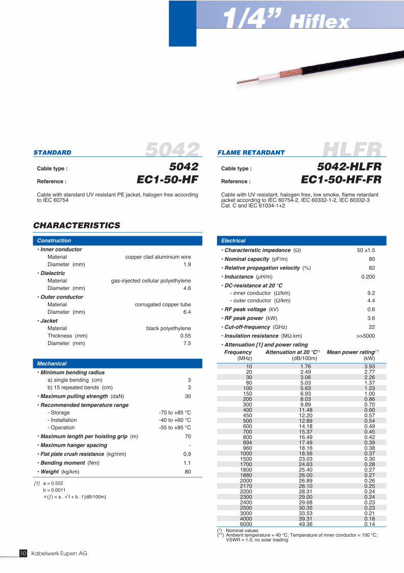
5042 HLFRSTANDARD
Cable type : 5042Reference : EC1-50-HFCable with standard UV resistant PE jacket, halogen free accordingto IEC 60754
FLAME RETARDANT
Cable type : 5042-HLFRReference : EC1-50-HF-FRCable with UV resistant, halogen free, low smoke, flame retardantjacket according to IEC 60754-2, IEC 60332-1-2, IEC 60332-3Cat. C and IEC 61034-1+2
Electrical
• Characteristic impedance (Ω) 50 ±1.5
• Nominal capacity (pF/m) 80
• Relative propagation velocity (%) 82
• Inductance (μH/m) 0.200
• DC-resistance at 20 °C- inner conductor (Ω/km) 9.2- outer conductor (Ω/km) 4.4
• RF peak voltage (kV) 0.6
• RF peak power (kW) 3.6
• Cut-off-frequency (GHz) 22
• Insulation resistance (MΩ.km) >>5000
• Attenuation [1] and power ratingFrequency Attenuation at 20 °C(*) Mean power rating(**)
(MHz) (dB/100m) (kW)
10 1.76 3.9320 2.49 2.7730 3.06 2.2680 5.03 1.37
100 5.63 1.23150 6.93 1.00200 8.03 0.86300 9.89 0.70400 11.48 0.60450 12.20 0.57500 12.89 0.54600 14.18 0.49700 15.37 0.45800 16.49 0.42894 17.49 0.39960 18.16 0.38
1000 18.56 0.371500 23.03 0.301700 24.63 0.281800 25.40 0.271880 26.00 0.272000 26.89 0.262170 28.10 0.252200 28.31 0.242300 29.00 0.242400 29.68 0.232500 30.35 0.233000 33.53 0.214000 39.31 0.186000 49.36 0.14
(*) Nominal values(**) Ambient temperature = 40 °C; Temperature of inner conductor = 100 °C;
VSWR = 1.0; no solar loading
Construction
• Inner conductorMaterial copper clad aluminium wireDiameter (mm) 1.9
• DielectricMaterial gas-injected cellular polyethyleneDiameter (mm) 4.6
• Outer conductorMaterial corrugated copper tubeDiameter (mm) 6.4
• JacketMaterial black polyethyleneThickness (mm) 0.55Diameter (mm) 7.5
Mechanical
• Minimum bending radiusa) single bending (cm) 3b) 15 repeated bends (cm) 3
• Maximum pulling strength (daN) 30
• Recommended temperature range- Storage -70 to +85 °C- Installation -40 to +60 °C- Operation -55 to +85 °C
• Maximum length per hoisting grip (m) 70
• Maximum hanger spacing -
• Flat plate crush resistance (kg/mm) 0.9
• Bending moment (Nm) 1.1
• Weight (kg/km) 80
CHARACTERISTICS
1/4” Hiflex
10 Kabelwerk Eupen AG
[1] a = 0.552b = 0.0011∝(ƒ) = a . √ f + b . f [dB/100m]
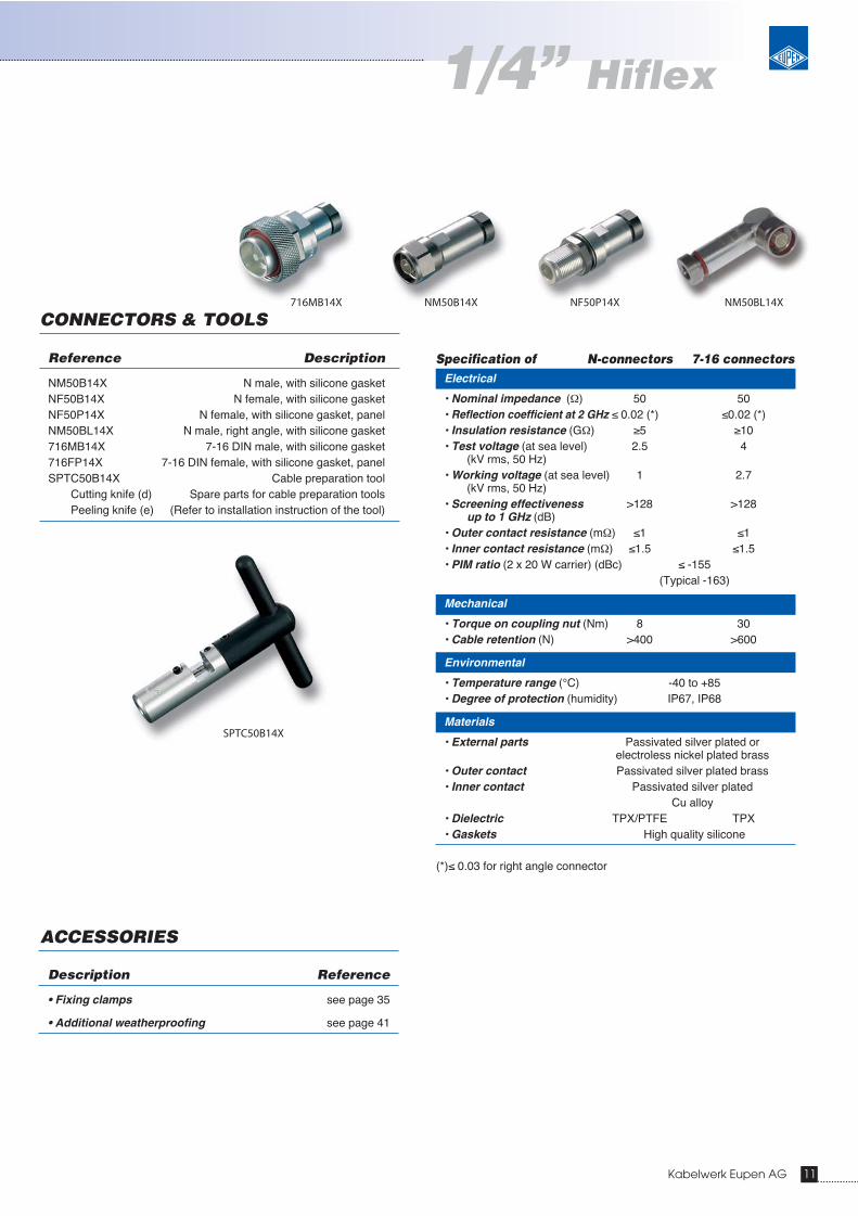
Specification of N-connectors 7-16 connectors
SPTC50B14X
NM50BL14XNF50P14X
Kabelwerk Eupen AG 11
Electrical
• Nominal impedance (Ω) 50 50• Reflection coefficient at 2 GHz ≤ 0.02 (*) ≤0.02 (*)• Insulation resistance (GΩ) ≥5 ≥10• Test voltage (at sea level) 2.5 4
(kV rms, 50 Hz)• Working voltage (at sea level) 1 2.7
(kV rms, 50 Hz)• Screening effectiveness >128 >128
up to 1 GHz (dB)• Outer contact resistance (mΩ) ≤1 ≤1• Inner contact resistance (mΩ) ≤1.5 ≤1.5• PIM ratio (2 x 20 W carrier) (dBc) ≤ -155
(Typical -163)
Mechanical
• Torque on coupling nut (Nm) 8 30• Cable retention (N) >400 >600
Environmental
• Temperature range (°C) -40 to +85• Degree of protection (humidity) IP67, IP68
Materials
• External parts Passivated silver plated or electroless nickel plated brass
• Outer contact Passivated silver plated brass• Inner contact Passivated silver plated
Cu alloy• Dielectric TPX/PTFE TPX• Gaskets High quality silicone
(*)≤ 0.03 for right angle connector
CONNECTORS & TOOLS
ACCESSORIES
Description Reference
• Fixing clamps see page 35
• Additional weatherproofing see page 41
Reference Description
NM50B14X N male, with silicone gasketNF50B14X N female, with silicone gasketNF50P14X N female, with silicone gasket, panelNM50BL14X N male, right angle, with silicone gasket716MB14X 7-16 DIN male, with silicone gasket716FP14X 7-16 DIN female, with silicone gasket, panelSPTC50B14X Cable preparation tool
Cutting knife (d) Spare parts for cable preparation toolsPeeling knife (e) (Refer to installation instruction of the tool)
NM50B14X716MB14X
1/4” Hiflex

5092 HLFRSTANDARD
Cable type : 5092Reference : EC4-50-HFCable with standard UV resistant PE jacket, halogen free accordingto IEC 60754
FLAME RETARDANT
Cable type : 5092-HLFRReference : EC4-50-HF-FRCable with UV resistant, halogen free, low smoke, flame retardantjacket according to IEC 60754-2, IEC 60332-1-2, IEC 60332-3Cat. C and IEC 61034-1+2
Electrical
• Characteristic impedance (Ω) 50 ±1
• Nominal capacity (pF/m) 82
• Relative propagation velocity (%) 82
• Inductance (μH/m) 0.200
• DC-resistance at 20 °C- inner conductor (Ω/km) 2.65- outer conductor (Ω/km) 3.0
• RF peak voltage (kV) 1.13
• RF peak power (kW) 12.8
• Cut-off-frequency (GHz) 13.2
• Insulation resistance (MΩ.km) >>5000
• Attenuation [1] and power ratingFrequency Attenuation at 20 °C(*) Mean power rating(**)
(MHz) (dB/100m) (kW)
10 0.96 9.9020 1.37 6.9630 1.68 5.6680 2.79 3.42
100 3.13 3.04150 3.88 2.46200 4.51 2.11300 5.60 1.70400 6.53 1.46450 6.96 1.37500 7.38 1.29600 8.15 1.17700 8.87 1.07800 9.55 1.00894 10.16 0.94960 10.57 0.90
1000 10.82 0.881500 13.62 0.701700 14.63 0.651800 15.12 0.631880 15.51 0.612000 16.08 0.592170 16.86 0.572200 17.00 0.562300 17.45 0.552400 17.89 0.532500 18.33 0.523000 20.42 0.474000 24.29 0.396000 31.21 0.31
(*) nominal values(**) Ambient temperature = 40 °C; Temperature of inner conductor = 100 °C;
VSWR = 1.0; no solar loading
Construction
• Inner conductorMaterial copper clad aluminium wireDiameter (mm) 3.55
• DielectricMaterial gas-injected cellular polyethyleneDiameter (mm) 9.0
• Outer conductorMaterial corrugated copper tubeDiameter (mm) 12.2
• JacketMaterial black polyethyleneThickness (mm) 0.65Diameter (mm) 13.5
Mechanical
• Minimum bending radiusa) single bending (cm) 3b) 15 repeated bends (cm) 4
• Maximum pulling strength (daN) 70
• Recommended temperature range- Storage -70 to +85 °C- Installation -40 to +60 °C- Operation -55 to +85 °C
• Maximum length per hoisting grip (m) 70
• Maximum hanger spacing 0.5
• Flat plate crush resistance (kg/mm) 1.7
• Bending moment (Nm) 2.7
• Weight (kg/km) 200
CHARACTERISTICS
1/2” Hiflex
12 Kabelwerk Eupen AG
[1] a = 0.30018b = 0.001327∝(ƒ) = a . √ f + b . f [dB/100m]
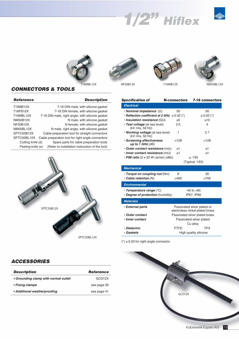
Specification of N-connectors 7-16 connectors
Kabelwerk Eupen AG 13
Electrical
• Nominal impedance (Ω) 50 50• Reflection coefficient at 2 GHz ≤ 0.02 (*) ≤ 0.02 (*)• Insulation resistance (GΩ) ≥5 ≥10• Test voltage (at sea level) 2.5 4
(kV rms, 50 Hz)• Working voltage (at sea level) 1 2.7
(kV rms, 50 Hz)• Screening effectiveness >128 >128
up to 1 GHz (dB)• Outer contact resistance (mΩ) ≤1 ≤1• Inner contact resistance (mΩ) ≤1 ≤1• PIM ratio (2 x 20 W carrier) (dBc) ≤ -155
(Typical -163)
Mechanical
• Torque on coupling nut (Nm) 8 30• Cable retention (N) >400 >700
Environmental
• Temperature range (°C) -40 to +85• Degree of protection (humidity) IP67, IP68
Materials
• External parts Passivated silver plated or electroless nickel plated brass
• Outer contact Passivated silver plated brass• Inner contact Passivated silver plated
Cu alloy• Dielectric PTFE TPX• Gaskets High quality silicone
(*) ≤ 0.03 for right angle connector
CONNECTORS & TOOLS
ACCESSORIES
Description Reference
• Grounding clamp with normal outlet GCS12X
• Fixing clamps see page 35
• Additional weatherproofing see page 41
Reference Description
716MB12X 7-16 DIN male, with silicone gasket716FB12X 7-16 DIN female, with silicone gasket716MBL12X 7-16 DIN male, right angle, with silicone gasketNM50B12X N male, with silicone gasketNF50B12X N female, with silicone gasketNM50BL12X N male, right angle, with silicone gasketSPTC50B12X Cable preparation tool for straight connectors SPTC50BL12X Cable preparation tool for right angle connectors
Cutting knife (d) Spare parts for cable preparation toolsPeeling knife (e) (Refer to installation instruction of the tool)
NF50B12X 716MB12X NM50BL12X716MBL12X
SPTC50B12X
GCS12X
1/2” Hiflex
SPTC50BL12X

5228X HLFRSTANDARD
Cable type : 5228XReference : EC5-50-HFCable with standard UV resistant PE jacket, halogen free accordingto IEC 60754
FLAME RETARDANT
Cable type : 5228X-HLFRReference : EC5-50-HF-FRCable with UV resistant, halogen free, low smoke, flame retardantjacket according to IEC 60754-2, IEC 60332-1-2, IEC 60332-3Cat. C and IEC 61034-1+2
Electrical
• Characteristic impedance (Ω) 50 ±1
• Nominal capacity (pF/m) 76
• Relative propagation velocity (%) 88
• Inductance (μH/m) 0.189
• DC-resistance at 20 °C- inner conductor (Ω/km) 2.5- outer conductor (Ω/km) 1.02
• RF peak voltage (kV) 3.0
• RF peak power (kW) 90
• Cut-off-frequency (GHz) 5.1
• Insulation resistance (MΩ.km) >>5000
• Attenuation [1] and power ratingFrequency Attenuation at 20 °C(*) Mean power rating(**)
(MHz) (dB/100m) (kW)
10 0.38 25.3420 0.54 17.8230 0.67 14.4980 1.11 8.74
100 1.24 7.79150 1.54 6.30200 1.79 5.41300 2.22 4.36400 2.59 3.74450 2.76 3.51500 2.92 3.31600 3.23 3.00700 3.51 2.75800 3.78 2.56894 4.02 2.40960 4.19 2.31
1000 4.28 2.261500 5.39 1.801700 5.79 1.671800 5.98 1.621880 6.14 1.582000 6.36 1.522170 6.67 1.452200 6.72 1.442300 6.90 1.402400 7.08 1.372500 7.25 1.333000 8.07 1.204000 9.60 1.016000 - -
(*) nominal values(**) Ambient temperature = 40 °C; Temperature of inner conductor = 100 °C;
VSWR = 1.0; no solar loading
Construction
• Inner conductorMaterial corrugated copper tubeDiameter (mm) 9.4
• DielectricMaterial gas-injected cellular polyethyleneDiameter (mm) 23.4
• Outer conductorMaterial corrugated copper tubeDiameter (mm) 25.0
• JacketMaterial black polyethyleneThickness (mm) 1.4Diameter (mm) 28.0
Mechanical
• Minimum bending radiusa) single bending (cm) 9b) 15 repeated bends (cm) 12.5
• Maximum pulling strength (daN) 130
• Recommended temperature range- Storage -70 to +85 °C- Installation -40 to +60 °C- Operation -55 to +85 °C
• Maximum length per hoisting grip (m) 70
• Maximum hanger spacing 1.2
• Flat plate crush resistance (kg/mm) 1.7
• Bending moment (Nm) 8.4
• Weight (kg/km) 460
CHARACTERISTICS
7/8” Hiflex
14 Kabelwerk Eupen AG
[1] a = 0.11905b = 0.000518∝(ƒ) = a . √ f + b . f [dB/100m]

Specification of N-connectors 7-16 connectorsElectrical
• Nominal impedance (Ω) 50 50• Reflection coefficient at 2 GHz ≤ 0.02 ≤0.02• Insulation resistance (GΩ) ≥5 ≥10• Test voltage (at sea level) 2.5 4
(kV rms, 50 Hz)• Working voltage (at sea level) 1 2.7
(kV rms, 50 Hz)• Screening effectiveness >128 >128
up to 1 GHz (dB)• Outer contact resistance (mΩ) ≤0.7 ≤0.7• Inner contact resistance (mΩ) ≤1 ≤1• PIM ratio (2 x 20 W carrier) (dBc) ≤ -155
(Typical -163)
Mechanical
• Torque on coupling nut (Nm) 8 30• Cable retention (N) >400 >1000
Environmental
• Temperature range (°C) -40 to +85• Degree of protection (humidity) IP67, IP68
Materials
• External parts Passivated silver plated or electroless nickel plated brass
• Outer contact Passivated silver plated brass• Inner contact Passivated silver plated
Cu alloy• Dielectric PTFE TPX• Gaskets High quality silicone
CONNECTORS & TOOL
ACCESSORIES
Description Reference
• Grounding clamp with parallel outlet GCS78PAR
• Fixing clamps see page 35
• Additional weatherproofing see page 41
• Lace-up hoisting grip HG-78Pre-laced hoisting grip HG-78-L
see page 37
716FV78MNF50A78M
SPTC50AV78X
7/8” Hiflex
Reference Description
716MV78M 7-16 DIN male, O-Ring716FV78M 7-16 DIN female, O-Ring716MA78M 7-16 DIN male, Sealant injection716FA78M 7-16 DIN female, Sealant injectionNM50V78M N male, O-RingNF50V78M N female, O-RingSPTC50AV78X Cable preparation tool
Inner ring (a) Spare parts for cable preparation toolOuter ring (b) (Refer to installation instruction of the tool)Spring (c)Cutting knife (d)Peeling knife (e)Flaring knife (f)
SIL-744 90ml Sealant for connectors using sealant injectionSIL-744 310 ml Sealant for connectors using sealant injection
Rem.: • Sealant for connectors using the sealant injection method must be purchased separately.
GCS78PAR
Kabelwerk Eupen AG 15

5328X HLFRSTANDARD
Cable type : 5328XReference : EC6-50-HFCable with standard UV resistant PE jacket, halogen free accordingto IEC 60754
FLAME RETARDANT
Cable type : 5328-HLFRReference : EC6-50-HF-FRCable with UV resistant, halogen free, low smoke, flame retardantjacket according to IEC 60754-2, IEC 60332-1-2, IEC 60332-3Cat. C and IEC 61034-1+2
Electrical
• Characteristic impedance (Ω) 50 ±1
• Nominal capacity (pF/m) 76
• Relative propagation velocity (%) 88
• Inductance (μH/m) 0.190
• DC-resistance at 20 °C- inner conductor (Ω/km) 1.8- outer conductor (Ω/km) 0.5
• RF peak voltage (kV) 4.25
• RF peak power (kW) 180
• Cut-off-frequency (GHz) 3.3
• Insulation resistance (MΩ.km) >>5000
• Attenuation [1] and power ratingFrequency Attenuation at 20 °C(*) Mean power rating(**)
(MHz) (dB/100m) (kW)
10 0.27 39.7320 0.38 27.9030 0.47 22.6680 0.79 13.62
100 0.89 12.12150 1.10 9.78200 1.28 8.39300 1.59 6.74400 1.86 5.76450 1.99 5.40500 2.11 5.09600 2.33 4.60700 2.55 4.22800 2.74 3.91894 2.92 3.67960 3.05 3.53
1000 3.12 3.441500 3.94 2.721700 4.25 2.531800 4.39 2.441880 4.51 2.382000 4.68 2.302170 4.91 2.192200 4.95 2.172300 5.09 2.112400 5.22 2.062500 5.35 2.013000 5.98 1.794000 - -6000 - -
(*) nominal values(**) Ambient temperature = 40 °C; Temperature of inner conductor = 100 °C;
VSWR = 1.0; no solar loading
Construction
• Inner conductorMaterial corrugated copper tubeDiameter (mm) 13.6
• DielectricMaterial gas-injected cellular polyethyleneDiameter (mm) 33.5
• Outer conductorMaterial corrugated copper tubeDiameter (mm) 36.0
• JacketMaterial black polyethyleneThickness (mm) 1.5Diameter (mm) 39.0
Mechanical
• Minimum bending radiusa) single bending (cm) 20b) 15 repeated bends (cm) 30
• Maximum pulling strength (daN) 200
• Recommended temperature range- Storage -70 to +85 °C- Installation -40 to +60 °C- Operation -55 to +85 °C
• Maximum length per hoisting grip (m) 70
• Maximum hanger spacing 1.4
• Flat plate crush resistance (kg/mm) 3.4
• Bending moment (Nm) 25
• Weight (kg/km) 830
CHARACTERISTICS
1-1/4” Hiflex
16 Kabelwerk Eupen AG
[1] a = 0.084b = 0.000461∝(ƒ) = a . √ f + b . f [dB/100m]

Specification of N-connectors 7-16 connectors
Kabelwerk Eupen AG 17
Electrical
• Nominal impedance (Ω) 50 50• Reflection coefficient at 2 GHz ≤0.02 ≤0.02• Insulation resistance (GΩ) ≥5 ≥10• Test voltage (at sea level) 2.5 4
(kV rms, 50 Hz)• Working voltage (at sea level) 1 2.7
(kV rms, 50 Hz)• Screening effectiveness >128 >128
up to 1 GHz (dB)• Outer contact resistance (mΩ) ≤0.5 ≤0.5• Inner contact resistance (mΩ) ≤1 ≤1• PIM ratio (2 x 20 W carrier) (dBc) ≤-155
(Typical -163)
Mechanical
• Torque on coupling nut (Nm) 8 30• Cable retention (N) >400 >1000
Environmental
• Temperature range (°C) -40 to +85• Degree of protection (humidity) IP67, IP68
Materials
• External parts Passivated silver plated or electroless nickel plated brass
• Outer contact Passivated silver plated brass• Inner contact Passivated silver plated
Cu alloy• Dielectric PTFE TPX• Gaskets High quality silicone
CONNECTORS & TOOL
ACCESSORIES
Description Reference
• Grounding clamp with parallel outlet GCS114PAR
• Fixing clamps see page 35
• Additional weatherproofing see page 41
• Lace-up hoisting grip HG-114Pre-laced hoisting grip HG-114-L
see page 37
Reference Description
716MV114M 7-16 DIN male, O-Ring716FV114M 7-16 DIN female, O-Ring716MA114M 7-16 DIN male, Sealant injection716FA114M 7-16 DIN female, Sealant injectionNM50V114M N male, O-RingNF50V114M N female, O-RingSPTC50AV114X Cable preparation tool
Inner ring (a) Spare parts for cable preparation toolOuter ring (b) (Refer to installation instruction of the tool)Spring (c)Cutting knife (d)Peeling knife (e)
SIL-744 90ml Sealant for connectors using sealant injectionSIL-744 310 ml Sealant for connectors using sealant injection
Rem.: • Sealant for connectors using the sealant injection method must be purchased separately.
716FA114MNM50V114M
SPTC50AV114X
GCS114PAR
1-1/4” Hiflex
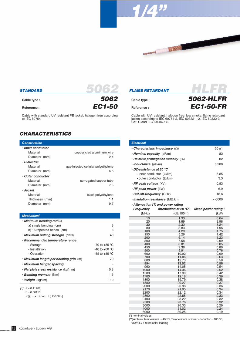
5062 HLFRSTANDARD
Cable type : 5062Reference : EC1-50Cable with standard UV resistant PE jacket, halogen free accordingto IEC 60754
FLAME RETARDANT
Cable type : 5062-HLFRReference : EC1-50-FRCable with UV resistant, halogen free, low smoke, flame retardantjacket according to IEC 60754-2, IEC 60332-1-2, IEC 60332-3Cat. C and IEC 61034-1+2
Electrical
• Characteristic impedance (Ω) 50 ±1
• Nominal capacity (pF/m) 82
• Relative propagation velocity (%) 82
• Inductance (μH/m) 0.200
• DC-resistance at 20 °C- inner conductor (Ω/km) 5.85- outer conductor (Ω/km) 3.3
• RF peak voltage (kV) 0.83
• RF peak power (kW) 6.9
• Cut-off-frequency (GHz) 18.6
• Insulation resistance (MΩ.km) >>5000
• Attenuation [1] and power ratingFrequency Attenuation at 20 °C(*) Mean power rating(**)
(MHz) (dB/100m) (kW)
10 1.33 5.6420 1.89 3.9830 2.32 3.2480 3.83 1.96
100 4.29 1.75150 5.29 1.42200 6.14 1.23300 7.58 0.99400 8.81 0.85450 9.38 0.80500 9.91 0.76600 10.92 0.69700 11.86 0.63800 12.73 0.59894 13.52 0.56960 14.05 0.54
1000 14.36 0.521500 17.90 0.421700 19.18 0.391800 19.79 0.381880 20.27 0.372000 20.98 0.362170 21.95 0.342200 22.12 0.342300 22.68 0.332400 23.22 0.322500 23.76 0.323000 26.33 0.294000 31.02 0.246000 39.25 0.19
(*) nominal values(**)Ambient temperature = 40 °C; Temperature of inner conductor = 100 °C;
VSWR = 1.0; no solar loading
Construction
• Inner conductorMaterial copper clad aluminium wireDiameter (mm) 2.4
• DielectricMaterial gas-injected cellular polyethyleneDiameter (mm) 6.5
• Outer conductorMaterial corrugated copper tubeDiameter (mm) 7.5
• JacketMaterial black polyethyleneThickness (mm) 1.1Diameter (mm) 9.7
Mechanical
• Minimum bending radiusa) single bending (cm) 3b) 15 repeated bends (cm) 8
• Maximum pulling strength (daN) 40
• Recommended temperature range- Storage -70 to +85 °C- Installation -40 to +60 °C- Operation -55 to +85 °C
• Maximum length per hoisting grip (m) 70
• Maximum hanger spacing -
• Flat plate crush resistance (kg/mm) 0.8
• Bending moment (Nm) 1.5
• Weight (kg/km) 110
CHARACTERISTICS
1/4”
18 Kabelwerk Eupen AG
[1] a = 0.41769b = 0.00115∝(ƒ) = a . √ f + b . f [dB/100m]

Specification of N-connectors 7-16 connectors
Kabelwerk Eupen AG 19
Electrical
• Nominal impedance (Ω) 50 50• Reflection coefficient at 2 GHz ≤0.02 (*) ≤0.02 (*)• Insulation resistance (GΩ) ≥5 ≥10• Test voltage (at sea level) 2.5 4
(kV rms, 50 Hz)• Working voltage (at sea level) 1 2.7
(kV rms, 50 Hz)• Screening effectiveness >128 >128
up to 1 GHz (dB)• Outer contact resistance (mΩ) ≤1 ≤1• Inner contact resistance (mΩ) ≤1.5 ≤1.5• PIM ratio (2 x 20 W carrier) (dBc) ≤ -155
(Typical -163)
Mechanical
• Torque on coupling nut (Nm) 8 30 • Cable retention (N) >400 >700
Environmental
• Temperature range (°C) -40 to +85• Degree of protection (humidity) IP67, IP68
Materials
• External parts Passivated silver plated or electroless nickel plated brass
• Outer contact Passivated silver plated brass• Inner contact Passivated silver plated
Cu alloy• Dielectric PTFE TPX• Gaskets High quality silicone
(*) ≤0.03 for right angle connector
CONNECTORS & TOOLS
ACCESSORIES
Description Reference
• Grounding clamp with normal outlet GCS14
• Fixing clamps see page 35
• Additional weatherproofing see page 41
Reference Description
716MA14 7-16 DIN male, O-Ring716FA14 7-16 DIN female, O-RingNM50A14 N male, O-RingNF50A14 N female, O-RingNM50AL14 N male, right angle, O-RingSPTC50A14 Cable preparation tool
Cutting knife (d) Spare parts for cable preparation toolsPeeling knife (e) (Refer to installation instruction of the tool)
NM50AL14NF50A14
GCS14
1/4”
SPTC50A14

5128 HLFRSTANDARD
Cable type : 5128Reference : EC4-50Cable with standard UV resistant PE jacket, halogen free accordingto IEC 60754
FLAME RETARDANT
Cable type : 5128-HLFRReference : EC4-50-FRCable with UV resistant, halogen free, low smoke, flame retardantjacket according to IEC 60754-2, IEC 60332-1-2, IEC 60332-3Cat. C and IEC 61034-1+2
Electrical
• Characteristic impedance (Ω) 50 ±1
• Nominal capacity (pF/m) 76
• Relative propagation velocity (%) 88
• Inductance (μH/m) 0.190
• DC-resistance at 20 °C- inner conductor (Ω/km) 1.48- outer conductor (Ω/km) 2.04
• RF peak voltage (kV) 1.6
• RF peak power (kW) 25.6
• Cut-off-frequency (GHz) 9.8
• Insulation resistance (MΩ.km) >>5000
• Attenuation [1] and power ratingFrequency Attenuation at 20 °C(*) Mean power rating(**)
(MHz) (dB/100m) (kW)
10 0.67 11.7420 0.95 8.2730 1.17 6.7380 1.93 4.08
100 2.17 3.64150 2.67 2.95200 3.10 2.54300 3.83 2.06400 4.46 1.77450 4.75 1.66500 5.02 1.57600 5.53 1.43700 6.01 1.31800 6.45 1.22894 6.85 1.15960 7.12 1.11
1000 7.28 1.081500 9.09 0.871700 9.74 0.811800 10.06 0.781880 10.30 0.772000 10.66 0.742170 11.16 0.712200 11.25 0.702300 11.53 0.682400 11.81 0.672500 12.09 0.653000 13.40 0.594000 15.81 0.506000 20.06 0.39
(*) nominal values(**) Ambient temperature = 40 °C; Temperature of inner conductor = 100 °C;
VSWR = 1.0; no solar loading
Construction
• Inner conductorMaterial copper clad aluminium wireDiameter (mm) 4.8
• DielectricMaterial gas-injected cellular polyethyleneDiameter (mm) 12.4
• Outer conductorMaterial corrugated copper tubeDiameter (mm) 13.7
• JacketMaterial black polyethyleneThickness (mm) 1.1Diameter (mm) 16.0
Mechanical
• Minimum bending radiusa) single bending (cm) 7b) 15 repeated bends (cm) 12.5
• Maximum pulling strength (daN) 100
• Recommended temperature range- Storage -70 to +85 °C- Installation -40 to +60 °C- Operation -55 to +85 °C
• Maximum length per hoisting grip (m) 70
• Maximum hanger spacing 1
• Flat plate crush resistance (kg/mm) 1.9
• Bending moment (Nm) 3.5
• Weight (kg/km) 235
CHARACTERISTICS
1/2”
20 Kabelwerk Eupen AG
[1] a = 0.2105b = 0.000625∝(ƒ) = a . √ f + b . f [dB/100m]
Specification of N-connectors 7-16 connectors
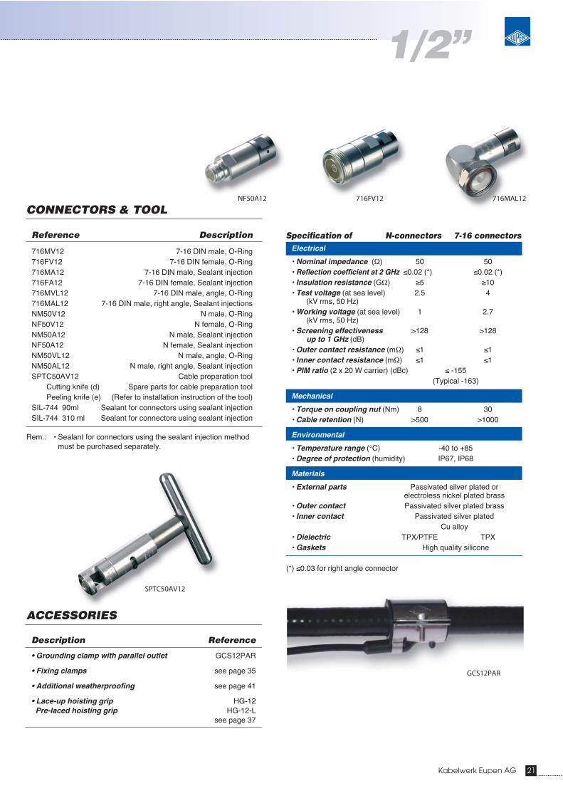
716MAL12
Kabelwerk Eupen AG 21
Electrical
• Nominal impedance (Ω) 50 50• Reflection coefficient at 2 GHz ≤0.02 (*) ≤0.02 (*)• Insulation resistance (GΩ) ≥5 ≥10• Test voltage (at sea level) 2.5 4
(kV rms, 50 Hz)• Working voltage (at sea level) 1 2.7
(kV rms, 50 Hz)• Screening effectiveness >128 >128
up to 1 GHz (dB)• Outer contact resistance (mΩ) ≤1 ≤1• Inner contact resistance (mΩ) ≤1 ≤1• PIM ratio (2 x 20 W carrier) (dBc) ≤ -155
(Typical -163)
Mechanical
• Torque on coupling nut (Nm) 8 30• Cable retention (N) >500 >1000
Environmental
• Temperature range (°C) -40 to +85• Degree of protection (humidity) IP67, IP68
Materials
• External parts Passivated silver plated or electroless nickel plated brass
• Outer contact Passivated silver plated brass• Inner contact Passivated silver plated
Cu alloy• Dielectric TPX/PTFE TPX• Gaskets High quality silicone
(*) ≤0.03 for right angle connector
CONNECTORS & TOOL
ACCESSORIES
Description Reference
• Grounding clamp with parallel outlet GCS12PAR
• Fixing clamps see page 35
• Additional weatherproofing see page 41
• Lace-up hoisting grip HG-12Pre-laced hoisting grip HG-12-L
see page 37
Reference Description
716MV12 7-16 DIN male, O-Ring716FV12 7-16 DIN female, O-Ring716MA12 7-16 DIN male, Sealant injection716FA12 7-16 DIN female, Sealant injection716MVL12 7-16 DIN male, angle, O-Ring716MAL12 7-16 DIN male, right angle, Sealant injectionsNM50V12 N male, O-RingNF50V12 N female, O-RingNM50A12 N male, Sealant injectionNF50A12 N female, Sealant injectionNM50VL12 N male, angle, O-RingNM50AL12 N male, right angle, Sealant injectionSPTC50AV12 Cable preparation tool
Cutting knife (d) Spare parts for cable preparation toolPeeling knife (e) (Refer to installation instruction of the tool)
SIL-744 90ml Sealant for connectors using sealant injectionSIL-744 310 ml Sealant for connectors using sealant injection
Rem.: • Sealant for connectors using the sealant injection method must be purchased separately.
716FV12NF50A12
SPTC50AV12
1/2”
GCS12PAR

HLFR
22 Kabelwerk Eupen AG
5228 ASTANDARD
Cable type : 5228 AReference : EC5-50-ACable with standard UV resistant PE jacket, halogen free accordingto IEC 60754
FLAME RETARDANT
Cable type : 5228A-HLFRReference : EC5-50A-FRCable with UV resistant, halogen free, low smoke, flame retardantjacket according to IEC 60754-2, IEC 60332-1-2, IEC 60332-3Cat. C and IEC 61034-1+2
Electrical
• Characteristic impedance (Ω) 50 ±1
• Nominal capacity (pF/m) 75
• Relative propagation velocity (%) 89
• Inductance (μH/m) 0.187
• DC-resistance at 20 °C- inner conductor (Ω/km) 1.34- outer conductor (Ω/km) 1.0
• RF peak voltage (kV) 2.9
• RF peak power (kW) 86
• Cut-off-frequency (GHz) 5.1
• Insulation resistance (MΩ.km) >>5000
• Attenuation [1] and power ratingFrequency Attenuation at 20 °C(*) Mean power rating(**)
(MHz) (dB/100m) (kW)
10 0.35 25.4620 0.50 17.9330 0.62 14.6080 1.02 8.85
100 1.14 7.89150 1.41 6.40200 1.63 5.51300 2.02 4.46400 2.35 3.83450 2.50 3.60500 2.64 3.41600 2.91 3.09700 3.16 2.85800 3.40 2.65894 3.61 2.49960 3.75 2.40
1000 3.83 2.351500 4.79 1.881700 5.13 1.751800 5.30 1.701880 5.43 1.662000 5.62 1.602170 5.88 1.532200 5.92 1.522300 6.07 1.482400 6.22 1.452500 6.37 1.413000 7.06 1.274000 8.33 1.086000 - -
(*) nominal values(**) Ambient temperature = 40 °C; Temperature of inner conductor = 100 °C;
VSWR = 1.0; no solar loading
Construction
• Inner conductorMaterial smooth copper tubeDiameter (mm) 9.3
• DielectricMaterial gas-injected cellular polyethyleneDiameter (mm) 23.5
• Outer conductorMaterial corrugated copper tubeDiameter (mm) 25.0
• JacketMaterial black polyethyleneThickness (mm) 1.4Diameter (mm) 28.0
Mechanical
• Minimum bending radiusa) single bending (cm) 10b) 15 repeated bends (cm) 25
• Maximum pulling strength (daN) 150
• Recommended temperature range- Storage -70 to +85 °C- Installation -40 to +60 °C- Operation -55 to +85 °C
• Maximum length per hoisting grip (m) 70
• Maximum hanger spacing 1.2
• Flat Plate Crush resistance (kg/mm) 1.4
• Bending moment (Nm) 11.6
• Weight (kg/km) 496
CHARACTERISTICS
7/8” AUltra Low Loss
[1] a = 0.1107b = 0.000333∝(ƒ) = a . √ f + b . f [dB/100m]

Specification of N-connectors 7-16 connectorsElectrical
• Nominal impedance (Ω) 50 50• Reflection coefficient at 2 GHz ≤0.02 ≤0.02• Insulation resistance (GΩ) ≥5 ≥10• Test voltage (at sea level) 2.5 4
(kV rms, 50 Hz)• Working voltage (at sea level) 1 2.7
(kV rms, 50 Hz)• Screening effectiveness >128 >128
up to 1 GHz (dB)• Outer contact resistance (mΩ) ≤0.7 ≤0.7• Inner contact resistance (mΩ) ≤1 ≤1• PIM ratio (2 x 20 W carrier) (dBc) ≤ -155
(Typical -163)
Mechanical
• Torque on coupling nut (Nm) 8 30• Cable retention (N) >400 >1000
Environmental
• Temperature range (°C) -40 to +85• Degree of protection (humidity) IP68
Materials
• External parts Passivated silver plated or electroless nickel plated brass
• Outer contact Passivated silver plated brass• Inner contact Passivated silver plated
Cu-Be and brass• Dielectric PTFE TPX• Gaskets High quality silicone
CONNECTORS & TOOL
ACCESSORIES
Description Reference
• Grounding clamp with parallel outlet GCS78PAR
• Fixing clamps see page 35
• Additional weatherproofing see page 41
• Lace-up hoisting grip HG-78Pre-laced hoisting grip HG-78-L
see page 37
Reference Description
716MV78MA 7-16 DIN male, O-Ring716FV78MA 7-16 DIN female, O-Ring716MA78MA 7-16 DIN male, Sealant injection716FA78MA 7-16 DIN female, Sealant injectionNM50V78MA N male, O-RingNF50V78MA N female, O-RingNM50A78MA N male, Sealant injectionNF50A78MA N female, Sealant injectionSPTC50AV78M Cable preparation tool
Inner ring (a) Spare parts for cable preparation toolOuter ring (b) (Refer to installation instruction of the tool)Spring (c)Cutting knife (d)Peeling knife (e)Flaring knife (f)
SIL-744 90ml Sealant for connectors using sealant injectionSIL-744 310 ml Sealant for connectors using sealant injection
Rem.: • Sealant for connectors using the sealant injection method must be purchased separately.
• EIA connectors available on request.
716FV78MANM50A78MA
SPTC50AV78M
GCS78PAR
Kabelwerk Eupen AG 23
7/8” A
5328 A HLFRSTANDARD
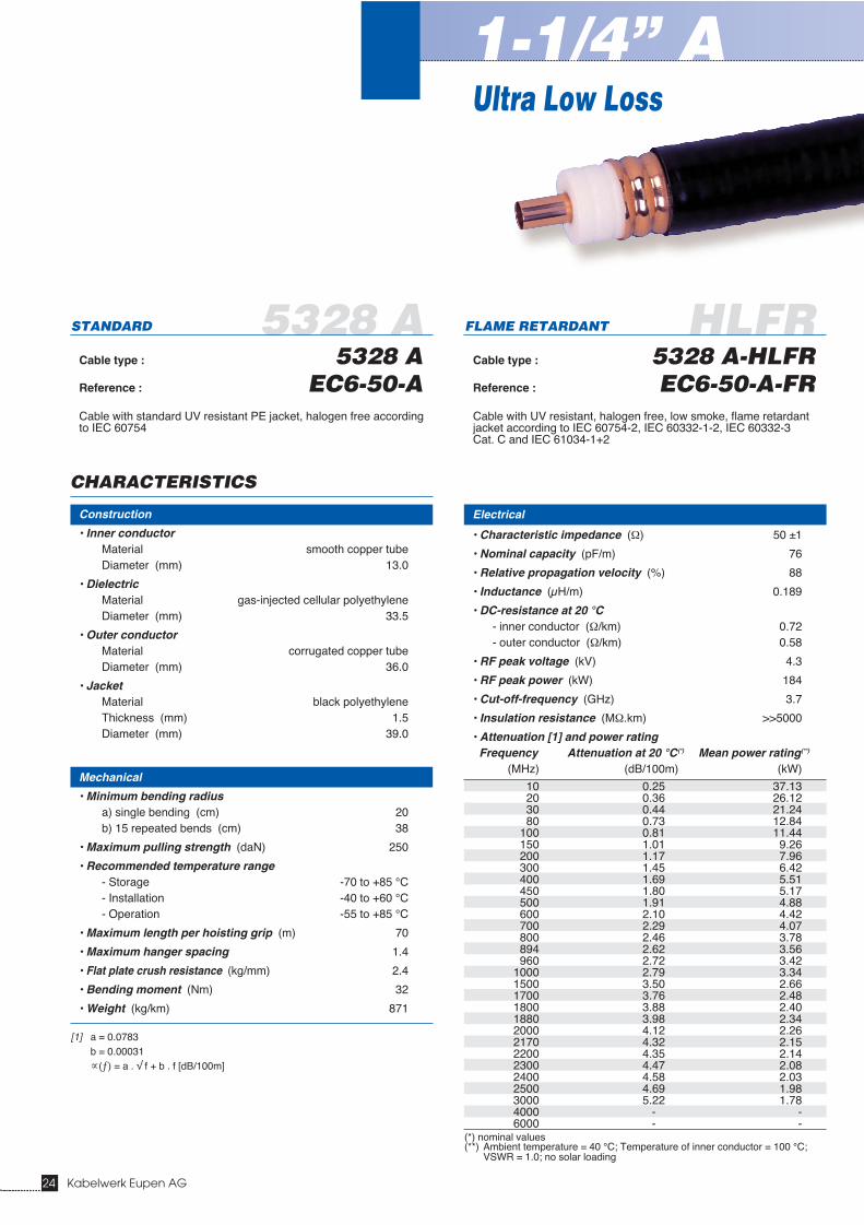
Cable type : 5328 AReference : EC6-50-ACable with standard UV resistant PE jacket, halogen free accordingto IEC 60754
FLAME RETARDANT
Cable type : 5328 A-HLFRReference : EC6-50-A-FRCable with UV resistant, halogen free, low smoke, flame retardantjacket according to IEC 60754-2, IEC 60332-1-2, IEC 60332-3Cat. C and IEC 61034-1+2
Electrical
• Characteristic impedance (Ω) 50 ±1
• Nominal capacity (pF/m) 76
• Relative propagation velocity (%) 88
• Inductance (μH/m) 0.189
• DC-resistance at 20 °C- inner conductor (Ω/km) 0.72- outer conductor (Ω/km) 0.58
• RF peak voltage (kV) 4.3
• RF peak power (kW) 184
• Cut-off-frequency (GHz) 3.7
• Insulation resistance (MΩ.km) >>5000
• Attenuation [1] and power ratingFrequency Attenuation at 20 °C(*) Mean power rating(**)
(MHz) (dB/100m) (kW)
10 0.25 37.1320 0.36 26.1230 0.44 21.2480 0.73 12.84
100 0.81 11.44150 1.01 9.26200 1.17 7.96300 1.45 6.42400 1.69 5.51450 1.80 5.17500 1.91 4.88600 2.10 4.42700 2.29 4.07800 2.46 3.78894 2.62 3.56960 2.72 3.42
1000 2.79 3.341500 3.50 2.661700 3.76 2.481800 3.88 2.401880 3.98 2.342000 4.12 2.262170 4.32 2.152200 4.35 2.142300 4.47 2.082400 4.58 2.032500 4.69 1.983000 5.22 1.784000 - -6000 - -
(*) nominal values(**) Ambient temperature = 40 °C; Temperature of inner conductor = 100 °C;
VSWR = 1.0; no solar loading
Construction
• Inner conductorMaterial smooth copper tubeDiameter (mm) 13.0
• DielectricMaterial gas-injected cellular polyethyleneDiameter (mm) 33.5
• Outer conductorMaterial corrugated copper tubeDiameter (mm) 36.0
• JacketMaterial black polyethyleneThickness (mm) 1.5Diameter (mm) 39.0
Mechanical
• Minimum bending radiusa) single bending (cm) 20b) 15 repeated bends (cm) 38
• Maximum pulling strength (daN) 250
• Recommended temperature range- Storage -70 to +85 °C- Installation -40 to +60 °C- Operation -55 to +85 °C
• Maximum length per hoisting grip (m) 70
• Maximum hanger spacing 1.4
• Flat plate crush resistance (kg/mm) 2.4
• Bending moment (Nm) 32
• Weight (kg/km) 871
CHARACTERISTICS
1-1/4” A
24 Kabelwerk Eupen AG
Ultra Low Loss
[1] a = 0.0783b = 0.00031∝(ƒ) = a . √ f + b . f [dB/100m]
Specification of N-connectors 7-16 connectors
Kabelwerk Eupen AG 25
Electrical
• Nominal impedance (Ω) 50 50• Reflection coefficient at 2 GHz ≤0.02 ≤0.02• Insulation resistance (GΩ) ≥5 ≥10• Test voltage (at sea level) 2.5 4
(kV rms, 50 Hz)• Working voltage (at sea level) 1 2.7
(kV rms, 50 Hz)• Screening effectiveness >128 >128
up to 1 GHz (dB)• Outer contact resistance (mΩ) ≤0.5 ≤0.5• Inner contact resistance (mΩ) ≤1 ≤1• PIM ratio (2 x 20 W carrier) (dBc) ≤ -155
(Typical -163)
Mechanical
• • Torque on coupling nut (Nm) 8 30• Cable retention (N) >400 >1000
Environmental
• Temperature range (°C) -40 to +85• Degree of protection (humidity) IP67, IP68
Materials
• External parts Passivated silver plated or electroless nickel plated brass
• Outer contact Passivated silver plated brass• Inner contact Passivated silver plated
Cu-Be and brass• Dielectric TPX/PTFE• Gaskets High quality silicone
CONNECTORS & TOOL
ACCESSORIES
Description Reference
• Grounding clamp with parallel outlet GCS114PAR
• Fixing clamps see page 35
• Additional weatherproofing see page 41
• Lace-up hoisting grip HG-114Pre-laced hoisting grip HG-114-L
see page 37
Reference Description
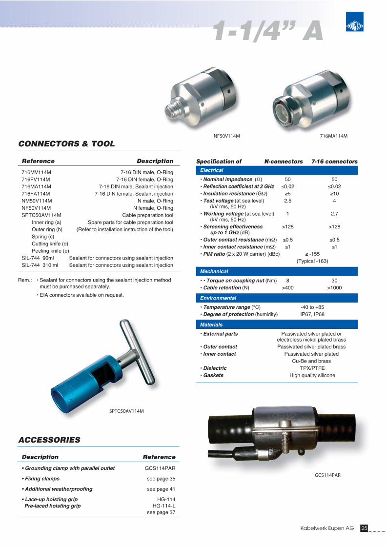
716MV114M 7-16 DIN male, O-Ring716FV114M 7-16 DIN female, O-Ring716MA114M 7-16 DIN male, Sealant injection716FA114M 7-16 DIN female, Sealant injectionNM50V114M N male, O-RingNF50V114M N female, O-RingSPTC50AV114M Cable preparation tool
Inner ring (a) Spare parts for cable preparation toolOuter ring (b) (Refer to installation instruction of the tool)Spring (c)Cutting knife (d)Peeling knife (e)
SIL-744 90ml Sealant for connectors using sealant injectionSIL-744 310 ml Sealant for connectors using sealant injection
Rem.: • Sealant for connectors using the sealant injection method must be purchased separately.
• EIA connectors available on request.
716MA114MNF50V114M
SPTC50AV114M
GCS114PAR
1-1/4” A
5438 A HLFRSTANDARD
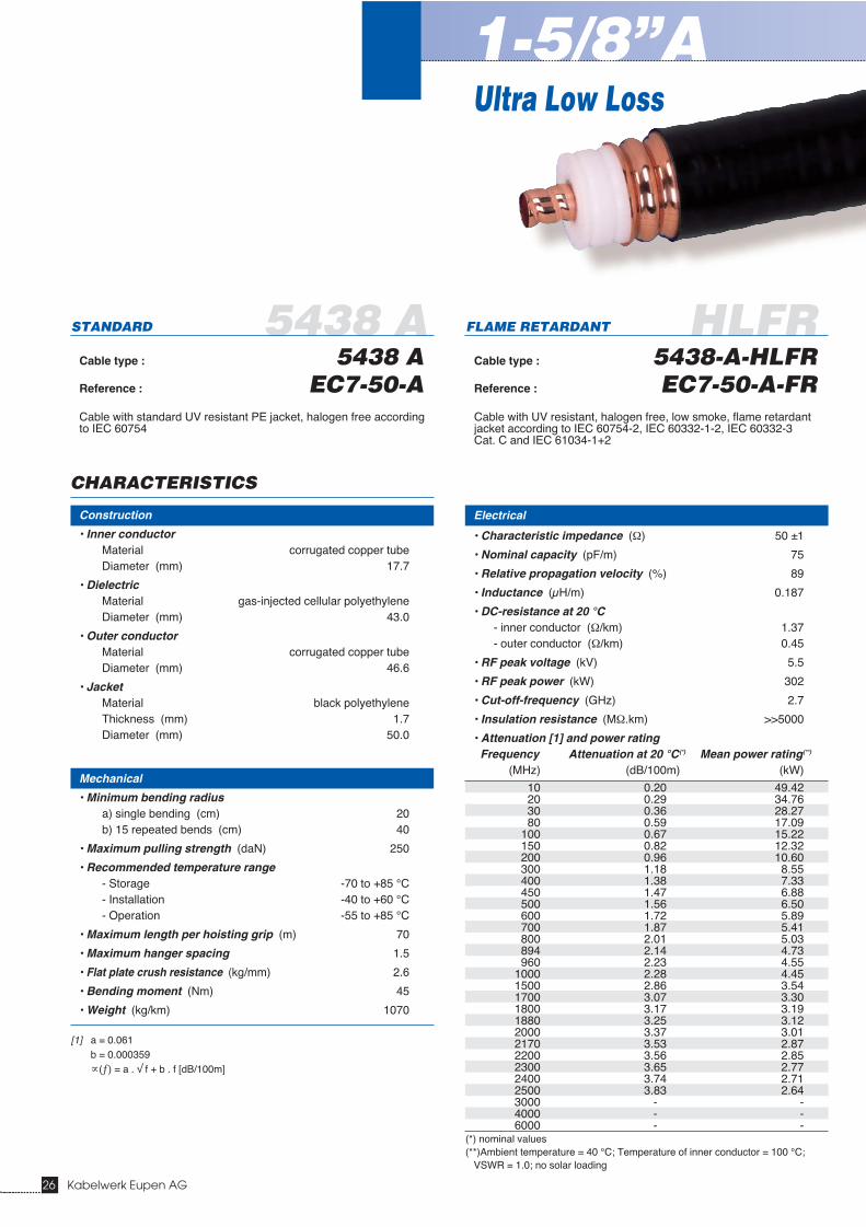
Cable type : 5438 AReference : EC7-50-ACable with standard UV resistant PE jacket, halogen free accordingto IEC 60754
FLAME RETARDANT
Cable type : 5438-A-HLFRReference : EC7-50-A-FRCable with UV resistant, halogen free, low smoke, flame retardantjacket according to IEC 60754-2, IEC 60332-1-2, IEC 60332-3Cat. C and IEC 61034-1+2
Electrical
• Characteristic impedance (Ω) 50 ±1
• Nominal capacity (pF/m) 75
• Relative propagation velocity (%) 89
• Inductance (μH/m) 0.187
• DC-resistance at 20 °C- inner conductor (Ω/km) 1.37- outer conductor (Ω/km) 0.45
• RF peak voltage (kV) 5.5
• RF peak power (kW) 302
• Cut-off-frequency (GHz) 2.7
• Insulation resistance (MΩ.km) >>5000
• Attenuation [1] and power ratingFrequency Attenuation at 20 °C(*) Mean power rating(**)
(MHz) (dB/100m) (kW)
10 0.20 49.4220 0.29 34.7630 0.36 28.2780 0.59 17.09
100 0.67 15.22150 0.82 12.32200 0.96 10.60300 1.18 8.55400 1.38 7.33450 1.47 6.88500 1.56 6.50600 1.72 5.89700 1.87 5.41800 2.01 5.03894 2.14 4.73960 2.23 4.55
1000 2.28 4.451500 2.86 3.541700 3.07 3.301800 3.17 3.191880 3.25 3.122000 3.37 3.012170 3.53 2.872200 3.56 2.852300 3.65 2.772400 3.74 2.712500 3.83 2.643000 - -4000 - -6000 - -
(*) nominal values(**)Ambient temperature = 40 °C; Temperature of inner conductor = 100 °C;
VSWR = 1.0; no solar loading
Construction
• Inner conductorMaterial corrugated copper tubeDiameter (mm) 17.7
• DielectricMaterial gas-injected cellular polyethyleneDiameter (mm) 43.0
• Outer conductorMaterial corrugated copper tubeDiameter (mm) 46.6
• JacketMaterial black polyethyleneThickness (mm) 1.7Diameter (mm) 50.0
Mechanical
• Minimum bending radiusa) single bending (cm) 20b) 15 repeated bends (cm) 40
• Maximum pulling strength (daN) 250
• Recommended temperature range- Storage -70 to +85 °C- Installation -40 to +60 °C- Operation -55 to +85 °C
• Maximum length per hoisting grip (m) 70
• Maximum hanger spacing 1.5
• Flat plate crush resistance (kg/mm) 2.6
• Bending moment (Nm) 45
• Weight (kg/km) 1070
CHARACTERISTICS
1-5/8”A
26 Kabelwerk Eupen AG
Ultra Low Loss
[1] a = 0.061b = 0.000359∝(ƒ) = a . √ f + b . f [dB/100m]
Specification of N-connectors 7-16 connectors
Kabelwerk Eupen AG 27
Electrical
• Nominal impedance (Ω) 50 50• Reflection coefficient at 2 GHz ≤0.02 ≤0.02• Insulation resistance (GΩ) ≥5 ≥10• Test voltage (at sea level) 2.5 4
(kV rms, 50 Hz)• Working voltage (at sea level) 1 2.7
(kV rms, 50 Hz)• Screening effectiveness >128 >128
up to 1 GHz (dB)• Outer contact resistance (mΩ) ≤0.5 ≤0.5• Inner contact resistance (mΩ) ≤1 ≤1• PIM ratio (2 x 20 W carrier) (dBc) ≤ -155
(Typical -163)
Mechanical
• Torque on coupling nut (Nm) 8 30• Cable retention (N) >400 >1000
Environmental
• Temperature range (°C) -40 to +85• Degree of protection (humidity) IP67, IP68
Materials
• External parts Passivated silver plated or electroless nickel plated brass
• Outer contact Passivated silver plated brass• Inner contact Passivated silver plated
Cu-Be and brass• Dielectric TPX / PTFE• Gaskets High quality silicone
CONNECTORS & TOOL
ACCESSORIES
Description Reference
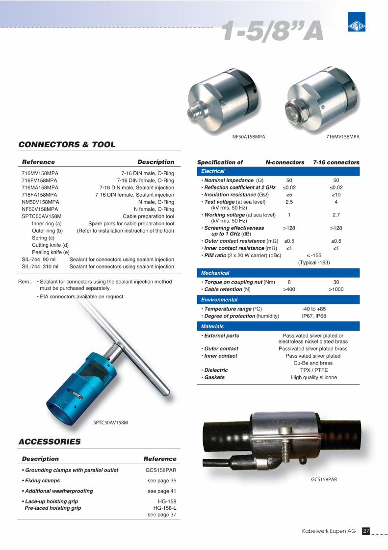
• Grounding clamps with parallel outlet GCS158PAR
• Fixing clamps see page 35
• Additional weatherproofing see page 41
• Lace-up hoisting grip HG-158Pre-laced hoisting grip HG-158-L
see page 37
Reference Description
716MV158MPA 7-16 DIN male, O-Ring716FV158MPA 7-16 DIN female, O-Ring716MA158MPA 7-16 DIN male, Sealant injection716FA158MPA 7-16 DIN female, Sealant injectionNM50V158MPA N male, O-RingNF50V158MPA N female, O-RingSPTC50AV158M Cable preparation tool
Inner ring (a) Spare parts for cable preparation toolOuter ring (b) (Refer to installation instruction of the tool)Spring (c)Cutting knife (d)Peeling knife (e)
SIL-744 90 ml Sealant for connectors using sealant injectionSIL-744 310 ml Sealant for connectors using sealant injection
Rem.: • Sealant for connectors using the sealant injection method must be purchased separately.
• EIA connectors available on request.
716MV158MPANF50A158MPA
SPTC50AV158M
GCS158PAR
1-5/8”A

5528 HLFRSTANDARD
Cable type : 5528Reference : EC12-50Cable with standard UV resistant PE jacket, halogen free accordingto IEC 60754
FLAME RETARDANT
Cable type : 5528-HLFRReference : EC12-50-FRCable with UV resistant, halogen free, low smoke, flame retardantjacket according to IEC 60754-2, IEC 60332-1-2, IEC 60332-3Cat. C and IEC 61034-1+2
Electrical
• Characteristic impedance (Ω) 50 ±1
• Nominal capacity (pF/m) 76
• Relative propagation velocity (%) 88
• Inductance (μH/m) 0.190
• DC-resistance at 20 °C- inner conductor (Ω/km) 0.55- outer conductor (Ω/km) 0.25
• RF peak voltage (kV) 6.8
• RF peak power (kW) 462
• Cut-off-frequency (GHz) 2.3
• Insulation resistance (MΩ.km) >>5000
• Attenuation [1] and power ratingFrequency Attenuation at 20 °C(*) Mean power rating(**)
(MHz) (dB/100m) (kW)
10 0.16 72.1920 0.23 50.4730 0.29 40.8680 0.49 24.30
100 0.55 21.55150 0.68 17.28200 0.80 14.74300 1.01 11.74400 1.19 9.96450 1.27 9.30500 1.35 8.75600 1.50 7.86700 1.65 7.18800 1.78 6.62894 1.91 6.20960 1.99 5.93
1000 2.04 5.791500 2.63 4.501700 2.84 4.161800 2.95 4.011880 3.03 3.902000 3.15 3.752170 3.32 3.562200 3.35 3.532300 - -2400 - -2500 - -3000 - -4000 - -6000 - -
(*) nominal values(**) Ambient temperature = 40 °C; Temperature of inner conductor = 100 °C;
VSWR = 1.0; no solar loading
Construction
• Inner conductorMaterial corrugated copper tubeDiameter (mm) 21.0
• DielectricMaterial gas-injected cellular polyethyleneDiameter (mm) 52.0
• Outer conductorMaterial corrugated copper tubeDiameter (mm) 56.0
• JacketMaterial black polyethyleneThickness (mm) 2.0Diameter (mm) 60.0
Mechanical
• Minimum bending radiusa) single bending (cm) 25b) 15 repeated bends (cm) 55
• Maximum pulling strength (daN) 300
• Recommended temperature range- Storage -70 to +85 °C- Installation -40 to +60 °C- Operation -55 to +85 °C
• Maximum length per hoisting grip (m) 70
• Maximum hanger spacing 1.8
• Flat Plate Crush resistance (kg/mm) 4.8
• Bending moment (kg/km) 90
• Weight (kg/km) 1960
CHARACTERISTICS
2-1/4”
28 Kabelwerk Eupen AG
[1] a = 0.05035b = 0.00045∝(ƒ) = a . √ f + b . f [dB/100m]
Specification of N-connectors 7-16 connectors
Kabelwerk Eupen AG 29
Electrical
• Nominal impedance (Ω) 50 50• Reflection coefficient at 2 GHz ≤0.025 ≤0.025• Insulation resistance (GΩ) ≥5 ≥10• Test voltage (at sea level) 2.5 4
(kV rms, 50 Hz)• Working voltage (at sea level) 1 2.7
(kV rms, 50 Hz)• Screening effectiveness >128 >128
up to 1 GHz (dB)• Outer contact resistance (mΩ) ≤0.5 ≤0.5• Inner contact resistance (mΩ) ≤1 ≤1• PIM ratio (2 x 20 W carrier) (dBc) ≤ -155
(Typical -163)
Mechanical
• Torque on coupling nut (Nm) 8 30• Cable retention (N) >400 >1000
Environmental
• Temperature range (°C) -40 to +85• Degree of protection (humidity) IP67, IP68
Materials
• External parts Passivated silver plated or electroless nickel plated brass
• Outer contact Passivated silver plated brass• Inner contact Passivated silver plated
Cu alloy• Dielectric PTFE TPX/PTFE• Gaskets High quality silicone
CONNECTORS & TOOL
ACCESSORIES
Type Reference Description
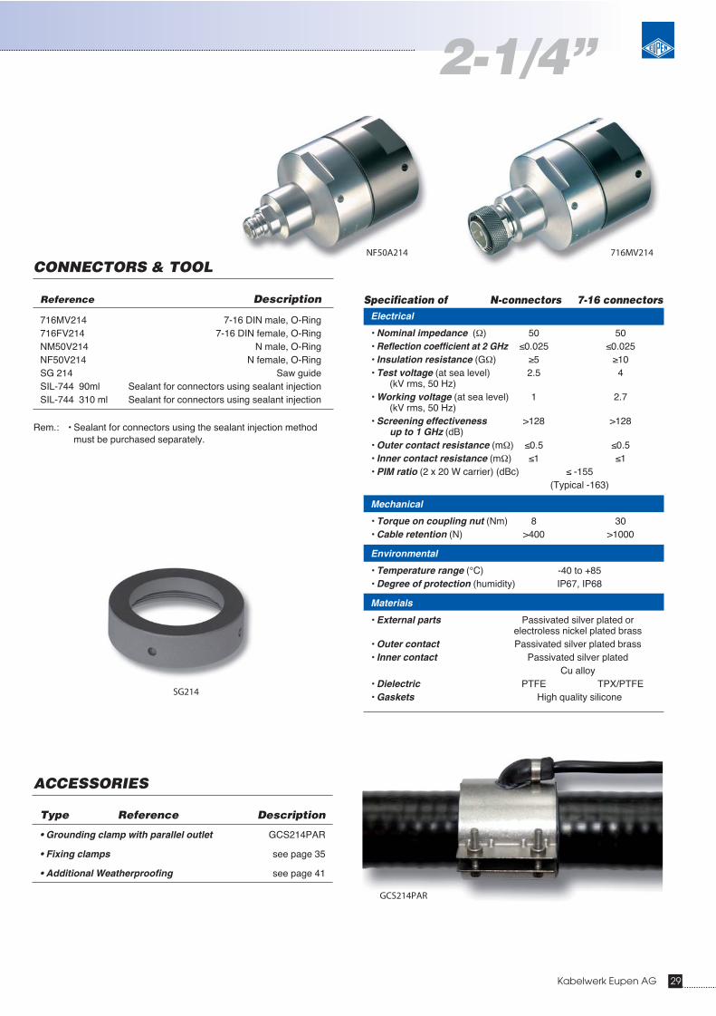
• Grounding clamp with parallel outlet GCS214PAR
• Fixing clamps see page 35
• Additional Weatherproofing see page 41
Reference Description
716MV214 7-16 DIN male, O-Ring716FV214 7-16 DIN female, O-RingNM50V214 N male, O-RingNF50V214 N female, O-RingSG 214 Saw guideSIL-744 90ml Sealant for connectors using sealant injectionSIL-744 310 ml Sealant for connectors using sealant injection
Rem.: • Sealant for connectors using the sealant injection method must be purchased separately.
716MV214NF50A214
SG214
2-1/4”
GCS214PAR
30 Kabelwerk Eupen AG
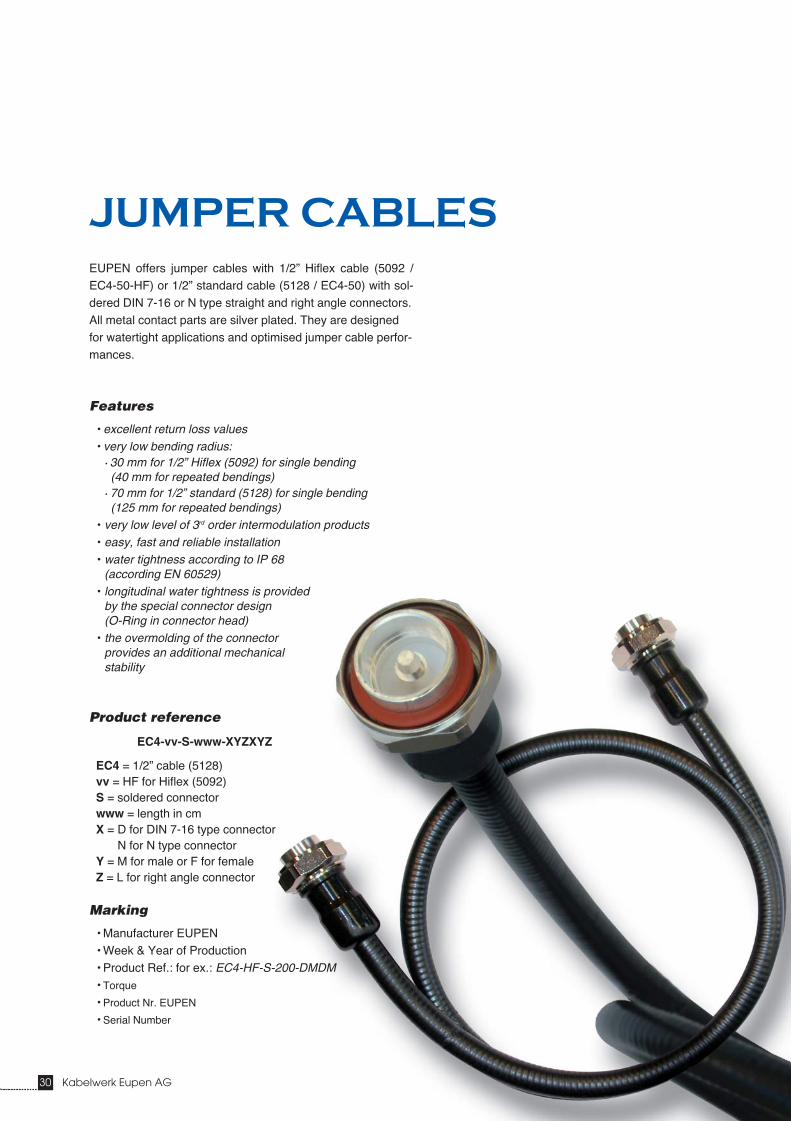
EUPEN offers jumper cables with 1/2” Hiflex cable (5092 /EC4-50-HF) or 1/2” standard cable (5128 / EC4-50) with sol-dered DIN 7-16 or N type straight and right angle connectors.All metal contact parts are silver plated. They are designedfor watertight applications and optimised jumper cable perfor-mances.
Features
• excellent return loss values• very low bending radius:
• 30 mm for 1/2” Hiflex (5092) for single bending(40 mm for repeated bendings)
• 70 mm for 1/2” standard (5128) for single bending(125 mm for repeated bendings)
• very low level of 3rd order intermodulation products • easy, fast and reliable installation• water tightness according to IP 68
(according EN 60529)• longitudinal water tightness is provided
by the special connector design (O-Ring in connector head)
• the overmolding of the connector provides an additional mechanical stability
Product reference
EC4-vv-S-www-XYZXYZ
EC4 = 1/2” cable (5128)vv = HF for Hiflex (5092)S = soldered connectorwww = length in cmX = D for DIN 7-16 type connector
N for N type connectorY = M for male or F for femaleZ = L for right angle connector
Marking
• Manufacturer EUPEN• Week & Year of Production• Product Ref.: for ex.: EC4-HF-S-200-DMDM• Torque
• Product Nr. EUPEN
• Serial Number
JUMPER CABLES

Kabelwerk Eupen AG 31
Jumper cables
Electrical
• Return loss [Min] for 7-16 straight - 7-16 straight (dB) -31 -307-16 straight - 7-16 angle (dB) -31 -26N straight - N straight (dB) -30 -28N straight - N angle (dB) -30 -27N straight - 7-16 straight (dB) -32 -30N straight - 7-16 angle (dB) -32 -27
• Attenuation per 100m at 20 °C (dB) 11.4 (+connectors) 17.8
• Power handling [min], continuous (W) 750 500
• Level of intermodulation productsTypical (dBc) -162 -162Max (dBc) -155 -155
• Impedance (Ohm) 50 ±1 50 ±1• RF Voltage rating [Peak] (V) 1130 1130• Velocity of propagation (%) 82 82
Mechanical
• Minimum bending radiussingle (mm) 30repeated (mm) 30
• Connector torque [nominal] (Nm) 28 (for 7-16 type)12 (for N type)
Environmental
• Temperature range (°C)Installation -40 to +60Operating -55 to +85
• Relative humidity (%) 10 to 100• General environmental corrosion and UV resistant
Specification 800-1000 MHz 1600-2200 MHz
Electrical
• Return loss [Min] for 7-16 straight - 7-16 straight (dB) -31 -307-16 straight - 7-16 angle (dB) -31 -26N straight - N straight (dB) -30 -28N straight - N angle (dB) -30 -27N straight - 7-16 straigth (dB) -32 -30N straight - 7-16 angle (dB) -32 -27
• Attenuation per 100m at 20 °C (dB) 7.9 (+connectors) 12.4
• Power handling [min], continuous (W) 750 500
• Level of intermodulation productsTypical (dBc) -162 -162Max (dBc) -155 -155
• Impedance (Ohm) 50 ±1 50 ±1• RF Voltage rating [Peak] (V) 1600 1600• Velocity of propagation (%) 82 82
Mechanical
• Minimum bending radiussingle (mm) 70repeated (mm) 125
• Connector torque [nominal] (Nm) 28 (for 7-16 type)12 (for N type)
Environmental
• Temperature range (°C)Installation -40 to +60Operating -55 to +85
• Relative humidity (%) 10 to 100• General environmental corrosion and UV resistant
Specification 800-1000 MHz 1600-2200 MHz
50921/2” HIFLEX JUMPER
Cable type : 5092Reference : EC4-50-HF
51281/2” STANDARD JUMPER
Cable type : 5128Reference : EC4-50
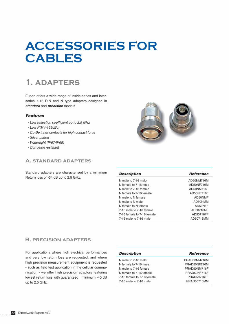
Eupen offers a wide range of inside-series and inter-series 7-16 DIN and N type adapters designed instandard and precision models.
Features
• Low reflection coefficient up to 2.5 GHz• Low PIM (-163dBc)• Cu-Be inner contacts for high contact force• Silver plated• Watertight (IP67/IP68)• Corrosion resistant
Standard adapters are characterised by a minimumReturn loss of -34 dB up to 2.5 GHz.
For applications where high electrical performancesand very low return loss are requested, and wherehigh precision measurement equipment is requested- such as field test application in the cellular commu-nication - we offer high precision adaptors featuringlowest return loss with guaranteed minimum -40 dBup to 2.5 GHz.
Description Reference
N male to 7-16 male AD50NM716MN female to 7-16 male AD50NF716MN male to 7-16 female AD50NM716FN female to 7-16 female AD50NF716FN male to N female AD50NMFN male to N male AD50NMMN female to N female AD50NFF7-16 male to 7-16 female AD50716MF7-16 female to 7-16 female AD50716FF7-16 male to 7-16 male AD50716MM
Description Reference
N male to 7-16 male PRAD50NM716MN female to 7-16 male PRAD50NF716MN male to 7-16 female PRAD50NM716FN female to 7-16 female PRAD50NF716F7-16 female to 7-16 female PRAD50716FF7-16 male to 7-16 male PRAD50716MM
A. standard adapters
B. precision adapters
32 Kabelwerk Eupen AG
ACCESSORIES FOR
CABLES
1. adapters

Kabelwerk Eupen AG 33
Accessories for cables
2. preset torque wrench selection guide
* only available on request
Connector Wrench size Max. Wrench Rear Nut ReferenceHead Thickness Torque
mm mm Nm
1/2” 19 7 20 TQ-34-F15
1/2” Hiflex 19 7 27 TQ-34-F20
7/8” + 7/8”A + 7/8” Hiflex 30 12 30 TQ-30MM-F22
1-1/4” + 1-1/4”A + 1-1/4” Hiflex 44 N/A 40 TQ-11116-F37
1-5/8”A 58 N/A 50 TQ-214-F37
2-1/4” 2-5/8” N/A 50 TQ-258-F37*
Connector Wrench size Max. Wrench Rear Nut ReferenceHead Thickness Torque
mm mm Nm
7-16 DIN MonoBloc male 32 N/A 25 TQ-114-F18-M
A. blue wrench handles for connector back nuts
B. red wrench handles for connector interfaces

34 Kabelwerk Eupen AG
3. grounding clamps
The optimal grounding of the transmissionline antenna to base station is a very weakpoint. In order to guarantee the best ground-ing we recommend the use of the EUPENgrounding clamps in order to ground thecoaxial outer conductor to the antenna toweror ground wire. The main features of theEupen grounding clamps are:
• Ultra quick and easy installation • No loose parts • Lightning resistant to 100kA light-
ning current (wave type 10/350 µs)• Very low contact resistance
< 1mOhm• Waterproof according IP68
(5 m of water 2,5 hours) without addi-tional tape or sealant
• Corrosion resistant• Reusable
GROUNDING CLAMPS
Reference GCS14 GCS38 GCS12X GCS12PAR GCS78PAR GCS114PAR GCS158PAR GCS214PAR
Cable size 1/4” 3/8” 1/2” Hiflex 1/2” 7/8”, 7/8”A & 7/8” Hiflex 1-1/4”A & 1-1/4” Hiflex 1-5/8”A 2-1/4”Outlet normal normal normal parallel parallel parallel parallel normalsee page 19 21 13 see above see above see above see above 31Cable cut (mm) 24 20 24 25 21 26 30 30
A. grounding clamps with parallel outlet
B. connector grounding kit “CGC” 12-158
Features
• Fast, easy and reliable installation• Low contact resistance• Corrosion resistant stainless steel material• Reusable• Only one model for all the connector sizes from 1/2” to 1-5/8”
Description
• Stainless steel connector grounding clamp• 60 cm lead with attachment lug and stainless steel M6
Allen screw, washer and nut.

Kabelwerk Eupen AG 35
Accessories for cables
A. new eucatecTM
rf cable clamps with lock nut
For further details please refer to technical specifications.
Features
• High durability given by non-corrosive metal components ofV2A stainless steel and calibrated saddles from ultravioletand aging resistant polyamide
• Mountable at ”C”-profile rails usual in radio systems as wellas flat sections to a maximum of 25 mm thickness andtubes up to a diameter of 25 mm (according to clamp type)
• Easy handling; the cable clamps (single type) consist ofmerely two elements
• New inlet design with crotchet on both sides to retain thesaddles in the clamp while fixing the cable
• Protection of the cable against a possible harm through thetensioning screw is ensured since the tensioning screw iscombined firmly with the polyamide shell
• Extra-secure hold is achieved by the use of a look nut
• All EUCATEC Cable Clamps are available in single, doubleor triple version
• Also available without look nut
40 or 50 mm
R25
8 mm9 mm
R11
EC
C-U
-...-
LN
EC
C-A
-...-
LN
EC
C-C
-...-
LN
EC
C-F
-...-
LN
EC
C-U
11-.
..-LN
Suitable profile types
• Standard C-Profile• Flat sections• Pipes• Right angle
4. fixing clamps
ECC-C-2x78-LN

36 Kabelwerk Eupen AG
OPTION: Angle Adapter for snap-in or clip hangers
Material : Stainless steel
EU-SH78L
EU-CH78NH
Other specific clamps are available on request
snap-in hangers clip hangers
Reference 1/2” 7/8” 1-1/4” 1-5/8” 2-1/4”
Snap-In EU-SH12L EU-SH78L EU-SH114L EU-SH158L EU-SH214LClip Hangers EU-CH12NH EU-CH78NH EU-CH114NH EU-CH158NH –
• For mainting on flat plate or angle • No additional hardware required• Orientable
Reference 1/2” 7/8” 1-1/4” 1-5/8”
Spring Clamp EU-ES9016 EU-ES9028 EU-ES9040 EU-ES9040
B. stainless steel clamp system
Description Reference
Angle Adapter EU-AA-SL
C. orientable stainless steel spring clamp
Kabelwerk Eupen AG 37
Accessories for cables
SIL-744
Reference 3/8” 1/2” 7/8” 1-1/4” 1-5/8” 2-1/4”
with 90 ml tube 26...30 20...25 13...15 7...9 4...5 3...4with 310 ml tube 90...103 69...86 44...51 24...31 13...17 10...13
With one tube the following quantities of connectors can be sealed:
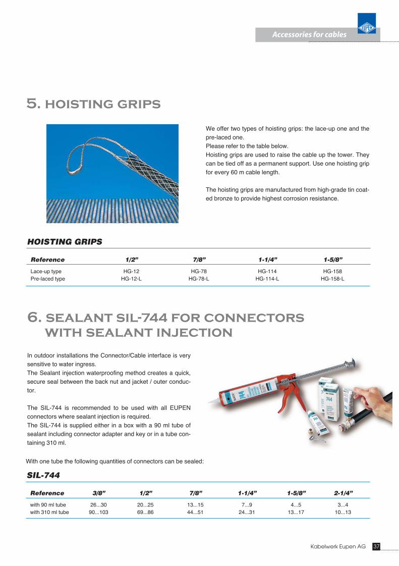
We offer two types of hoisting grips: the lace-up one and thepre-laced one.Please refer to the table below.Hoisting grips are used to raise the cable up the tower. Theycan be tied off as a permanent support. Use one hoisting gripfor every 60 m cable length.
The hoisting grips are manufactured from high-grade tin coat-ed bronze to provide highest corrosion resistance.
5. hoisting grips
HOISTING GRIPS
Reference 1/2” 7/8” 1-1/4” 1-5/8”
Lace-up type HG-12 HG-78 HG-114 HG-158Pre-laced type HG-12-L HG-78-L HG-114-L HG-158-L
6. sealant sil-744 for connectors
with sealant injection
In outdoor installations the Connector/Cable interface is verysensitive to water ingress.The Sealant injection waterproofing method creates a quick,secure seal between the back nut and jacket / outer conduc-tor.
The SIL-744 is recommended to be used with all EUPENconnectors where sealant injection is required.The SIL-744 is supplied either in a box with a 90 ml tube ofsealant including connector adapter and key or in a tube con-taining 310 ml.
38 Kabelwerk Eupen AG
ES-12-114
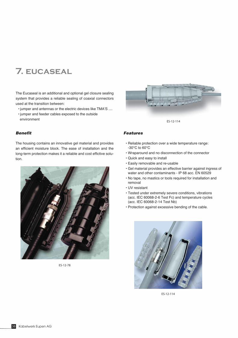
7. eucaseal
The Eucaseal is an additional and optional gel closure sealingsystem that provides a reliable sealing of coaxial connectorsused at the transition between:
• jumper and antennas or the electric devices like TMA’S ....• jumper and feeder cables exposed to the outside environment
Features
• Reliable protection over a wide temperature range: -30°C to 60°C
• Wraparound and no disconnection of the connector• Quick and easy to install• Easily removable and re-usable• Gel material provides an effective barrier against ingress of
water and other contaminants - IP 68 acc. EN 60529• No tape, no mastics or tools required for installation and
removal• UV resistant• Tested under extremely severe conditions, vibrations
(acc. IEC 60068-2-6 Test Fc) and temperature cycles (acc. IEC 60068-2-14 Test Nb)
• Protection against excessive bending of the cable.
Benefit
The housing contains an innovative gel material and providesan efficient moisture block. The ease of installation and thelong-term protection makes it a reliable and cost effictive solu-tion.
ES-12-78
ES-12-114

Kabelwerk Eupen AG 39
Accessories for cables
EUCASEAL
Application 1/2” jumper to 1/2” jumper to 1/2” jumper to 1/2” jumper toantenna or box 7/8” feeder 1-1/4” feeder 1-5/8” feeder
Reference ES-12-BOX ES-12-78 ES-12-114 ES-12-158
Cable type 1/2” & 1/2” Hiflex 1/2” & 1/2” Hiflex 1/2” & 1/2” Hiflex 1/2” & 1/2” Hiflexto 7/8”, 7/8”A or 7/8” Hiflex to 1-1/4”A or 1-1/4” Hiflex to 1-5/8”A
Connector type only DIN 7-16 N or 7-16 N or 7-16 N or 7-16- max. length 60 mm
- max. body diameter 27 mm- nominal distance between
panel connectors 45 mm
Available in black and grey
ES-12-BOX
ES-12-BOX

40 Kabelwerk Eupen AG
The lightning arrester offers an additional protectionfor the BTS against lightning damages.
EUPEN Quarter Wave protector can be used inwideband applications from 800 to 2500 MHz.
8. quarter wave lightning arrester
Features
• Quick and easy to install• Basic range from 800 to 2500 MHz• Arrester method: 1/4 Wave
Technical Data
• Impedance: 50 Ohm • Insertion loss: < 0.1 dB• Return Loss (VSWR): < 1.20• Surge current handling capability at least 20 kA (8/20 μS) up to 100 kA (following type)• Residual pulse energy ≤ 0.5 μJ (3kA@8/20μS)• Residual pulse voltage ≤ ±3V (3kA@8/20μS)• Max. power: 100W• Available in DIN and N type
Reference
for ex.: EU-LA-QW-800-2500-DM-DF
EU-LA-QW-800-2500-DMDF

Kabelwerk Eupen AG 41
Accessories for cables
If additional weatherproofing is required, it can beobtained with appropriate adhesive tapes wrappedaround the cable/connector interface.
Eupen supplies a weatherproofing tape kit for addi-tional protection of connector, cable and jumper inter-faces. The tape kit includes selffusing butyl tape(65 mm x 2 m) and black PVC tape (25 mm x 10 m).
The following table indicates the quantity of connec-tors or splices which can be protected by tape kit:
9. weatherproofing tape kit
WEATHERPROOFING TAPE KIT
Cable/Connector 1/4” & 3/8” 1/2” & 1/2”X 7/8” 1-1/4” 1-5/8”
Single connector 10 9 7 5 3Splice 6 5 4 3 2
Aw
W
d D
42 Kabelwerk Eupen AG
CABLE PACKING AND
HANDLING INFORMATION
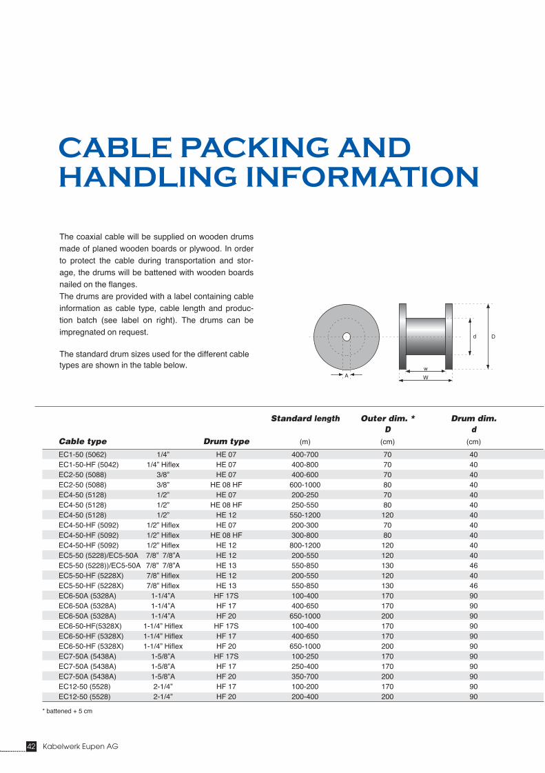
The coaxial cable will be supplied on wooden drumsmade of planed wooden boards or plywood. In orderto protect the cable during transportation and stor-age, the drums will be battened with wooden boardsnailed on the flanges.The drums are provided with a label containing cableinformation as cable type, cable length and produc-tion batch (see label on right). The drums can beimpregnated on request.
The standard drum sizes used for the different cabletypes are shown in the table below.
* battened + 5 cm
Standard length Outer dim. * Drum dim.D d
Cable type Drum type (m) (cm) (cm)
EC1-50 (5062) 1/4” HE 07 400-700 70 40EC1-50-HF (5042) 1/4” Hiflex HE 07 400-800 70 40EC2-50 (5088) 3/8” HE 07 400-600 70 40EC2-50 (5088) 3/8” HE 08 HF 600-1000 80 40EC4-50 (5128) 1/2” HE 07 200-250 70 40EC4-50 (5128) 1/2” HE 08 HF 250-550 80 40EC4-50 (5128) 1/2” HE 12 550-1200 120 40EC4-50-HF (5092) 1/2” Hiflex HE 07 200-300 70 40EC4-50-HF (5092) 1/2” Hiflex HE 08 HF 300-800 80 40EC4-50-HF (5092) 1/2” Hiflex HE 12 800-1200 120 40EC5-50 (5228)/EC5-50A 7/8” 7/8”A HE 12 200-550 120 40EC5-50 (5228))/EC5-50A 7/8” 7/8”A HE 13 550-850 130 46EC5-50-HF (5228X) 7/8” Hiflex HE 12 200-550 120 40EC5-50-HF (5228X) 7/8” Hiflex HE 13 550-850 130 46EC6-50A (5328A) 1-1/4”A HF 17S 100-400 170 90EC6-50A (5328A) 1-1/4”A HF 17 400-650 170 90EC6-50A (5328A) 1-1/4”A HF 20 650-1000 200 90EC6-50-HF(5328X) 1-1/4” Hiflex HF 17S 100-400 170 90EC6-50-HF (5328X) 1-1/4” Hiflex HF 17 400-650 170 90EC6-50-HF (5328X) 1-1/4” Hiflex HF 20 650-1000 200 90EC7-50A (5438A) 1-5/8”A HF 17S 100-250 170 90EC7-50A (5438A) 1-5/8”A HF 17 250-400 170 90EC7-50A (5438A) 1-5/8”A HF 20 350-700 200 90EC12-50 (5528) 2-1/4” HF 17 100-200 170 90EC12-50 (5528) 2-1/4” HF 20 200-400 200 90

Kabelwerk Eupen AG 43
Packing information
Drum label
Outer width Inner width Shaft hole Drum freight Drum weight Cable weightW w A Volume drum/battened drum
(cm) (cm) (cm) (m3) (kg) (kg/km)
41.6 40 6.5 0.21 7/9 11041.6 40 6.5 0.21 7/9 8041.6 40 6.5 0.21 7/9 14054 49 6.5 0.35 16/35 140
41.6 40 6.5 0.21 7/9 23554 49 6.5 0.35 16/35 23554 49 6.5 0.78 25/60 235
41.6 40 6.5 0.21 7/9 20054 49 6.5 0.35 16/35 20054 49 8 0.78 25/60 20054 49 8 0.78 25/60 53078 74 8 1.32 40/90 53054 49 8 0.78 25/60 46078 74 8 1.32 40/90 46070 64 9 2.20 232/320 970104 98 9 3.03 380/471 970116 104 9 4.75 440/556 97070 64 9 2.20 232/320 830104 98 9 3.03 380/472 830116 104 9 4.75 440/556 83070 64 9 2.20 232/320 1200104 98 9 3.03 380/472 1200116 104 9 4.75 440/556 1200104 98 9 3.03 380/472 1960116 104 9 4.75 440/556 1960

Malmedyer Str. 9 - B-4700 EUPEN - BELGIENTel.: +32(0)87.59.70.00 Fax: +32(0)87.59.71.00
http://www.eupen.com e-mail:[email protected]
11/2
008
- 15
00 p
c (K
)