incipient failure detection in power transformers … failure detection in power transformers...
TRANSCRIPT

Incipient Failure Detection in Power Transformers through Frequency Sweep
Response
Alberto Avalos Gonzalez, Jaime Cerda Jacobo, Servando Sanchez Ruíz Abstract - Solid faults identification in power transformers can be accomplished throughout a number of different routine tests such as: low tension TTR, power factor and excitation tests. However, with the presence of incipient faults, it is usually a necessity for its excitation and identification the application of auxiliary tests, such as: high tension TTR (from 2.5 KV to 10 KV), leakage reactance and sweep frequency response, among others. These set of tests are normally capable of exciting, and in consequence to uncover these types of faults. This work shows a particular case of a fault in a power autotransformer tap changer, where the presence of a fault was intermittent. Evidence is shown of at least two tests which were able to uncover the fault. This document intends to highlight the importance of detecting incipient faults, to decide whether to energize the transformer or not, with the smallest risk for the equipment and the operative personnel. Index Terms - Incipient Faults, Sweep Frequency, Electrical Tests.
I. INTRODUCTION
Faults which present themselves upon the power transformers e.g. short circuits, winding deformities, insulation losses, problems in the tap changers, can be easily identified by routine tests; phenomena like winding telescoping represent geometry changes within them, that can be identified with tests like the power factor, due to the change in the capacitance measured in this test; the reactance dispersion test detects the changes on the own impendence of the transformer, and lastly, the sweep frequency test can clearly show the changes in the operation modes of the transformer, due to the variation of its geometry [1]. On the other hand, the excitation test, as well as both low and high tension TTR test, are not able of excite these kinds of faults for its detection unless a rupture on the winding insulation is present to allow the electric arc between coils, or in-between winding and core that clearly excites the failure, making it evident. At the same time, the presence of electric arcs will be reflected on the accumulation of dissolved gases in oil, where a chromographic test of the same will show its presence.
Manuscript received July 23, 2012; revised August 24, 2012. J. A. Avalos is with the Electrical Engineering School, Universidad
Michoacana, Morelia, MX (email: [email protected]). J. Cerda is with the Electrical Engineering School, Universidad Michoacana, Morelia, MX (4433223500 ext.1177; email: [email protected]). S. Sánchez is with the Comision Federal de Electricidad, División Centro Occidente, Morelia, México (email: [email protected]).
In this work a particular case is presented to confirm the previous statements, involving a fault in the tap changer of a power autotransformer, whose characteristics are: 12/16/20 MVA, 3ϕ, Y-Y-Δ, 110/69/13.8KV. This fault was originated when an atmospheric discharge onto the feeding transmission line fired the differential protection which damaged the transformer tap changer. The peculiarity of this fault was that the damage caused in the tap changer was not evidenced by any of the electrical tests mentioned above, including the sweep frequency test. In one of the realized movements in the tap changers, the fault was declared, allowing its excitation through the frequency sweep, high tension TTR and the leakage reactance tests. The risk to the transformer that comes from not detecting in time the fault, foreseeing its eventual re-energizing, can provoke a permanent damage itself that would end at a loss of thousands of dollars. Different types of incipient faults like this one do present themselves eventually, for instance the loss of insulation at the common point of the star of the transformer. Therefore, it is necessary to guarantee the detection of these incipient faults to avoid their evolution to solid faults that would produce an imminent damage to the transformer. At least two cases have been detected by the authors of this work, in which none of the faults were capable of evidencing the fault, leading to its evolution to solid faults that damaged the transformers with its obvious consequences. Certain types of incipient faults can be excited by high tension tests like: excitation current and 10 KV TTR. However, faults like bad welds in the braids that connect the tap changer are not detected by these types of tests. But these types of faults can be identified by tests that respond to the frequency and resistance of the windings. Those faults that involve geometry changes of the windings, originated by the axial or radial movement/displacement of the same windings, are efficiently detected by the sweep frequency test. For this type of incipient fault, the ability to identify the damage level that the transformers present is necessary to assess the risk of taking them out of operation for its internal inspection. The sweep frequency response test bases its analysis on the fact that the internal structure of a transformer represents a set of multi-coupled RLC circuits, which reflect inductive and capacitive couplings between the windings, the core and the tank of the transformer, where the presence of the oil where the transformer is immersed, will accentuate the capacitive effects in its interior. In different frequency ranges, the
Proceedings of the World Congress on Engineering and Computer Science 2012 Vol II WCECS 2012, October 24-26, 2012, San Francisco, USA
ISBN: 978-988-19252-4-4 ISSN: 2078-0958 (Print); ISSN: 2078-0966 (Online)
WCECS 2012

predominant effects will be integrated, like the core for low frequencies, the loss of fastening elements of the windings will allow their displacement that would accentuate its inductive effect reflected in a frequency range of 400 Hz to 700 KHz. Any windings or core displacement of the transformer would result in a change of impendence in a given frequency range. This in turn would allow the detection of the different faults present inside of the transformer. That will be reflected as a change in its geometry, if compared with a plant reference o a site with faultless condition [1]. This work is specifically focused on the Sweep Frequency Response Analysis (SFRA), for the identification of solid or incipient faults in transformers [2]. This technique allows, through the application of a small voltage in a frequency range from 20 Hz to 2 MHz (or larger), to excite the resonance frequencies of the transformer, identifying this with its own geometry. Thus any change in its geometry will be reflected as a displacement of the resonance points, or in the trajectory of the obtained response, therefore allowing the detection of the internal faults in the transformer. The method bases its analysis in two different ways: the first one consists of counting with the plant test of the transformer [3], known as its fingerprint. This test allows to follow up on the internal condition of the windings and core of the transformer through its comparison with future tests, to be realized periodically or, if preferred, by exposing the transformer to great electrical efforts due to severe faults, or upon displacements of the transformers due to a possible re-location, or to seismic movements of great relevance. This will allow the detection of variations in the sweep frequency response to determine the existence of internal faults within the transformer. The second way consists, if no previous tests of the transformer are available, in comparing the results either with twin units or between the responses obtained in the distinct transformer phases. To this end, it is assumed that lateral phases should behave identically, due to the fact that magnetic trajectories are symmetrical and that the previous knowledge of the other transformer typical responses are known.
II. THE SFRA TEST
The SFRA test bases its analysis mainly on counting with an industry referenced test of the transformers. However, in most countries, it can be found transformers with more than 20, 30 or 40 years in operation without a reference test. Nevertheless, it is still necessary the actual estate information that guarantees its safe operation for both the electrical red and the personal that operates it. The SFRA test, next to other electrical tests, allows the detection of those units that should not be in operation and the ones that can still operate with an adequate safety margin. In some countries, particularly the CFE-Division Centro Occidente, Mexico (DCO), they have chosen those transformers with years of operations, identified with an acceptable security level, operated with relatively low load levels that allow them to increment their expected life, and
thus achieving to minimize the inversion costs of the electrical company in the short term. Below, the expected typical responses, when the established tests by the SFRA tests applied to power transformers, are shown. These depend on the connections of the windings, whether they are open or short circuit. It is also assumed that the frequency ranges of affectation for the main faults that appear in a transformer have been identified.
III. TYPICAL RESPONSE FOR A ∆-Y TRANSFORMER
The main tests that are applied to the transformer with this method are: high and low tension open circuit tests, short circuit tests, the last ones are realized by feeding the high tension whilst the low tension is in short circuit. The typical responses of these tests for a transformer connected in ∆-Y are shown in Figure 1.
Fig. 1. Typical Response for a ∆-Y connection
This figure shows the typical response for the open-circuit tests both for the delta connection and the star connection. Similarly, it demonstrates the response of the short circuit. It can be observed the response on the open-circuit test of the lateral phases and the delta connection as well as for the star connection are identical. On the other hand, the central phase on both cases reflect a bigger impendency due to the difference in the flow trajectories that present the magnetic structure of the transformer, and different resonance points. As for the short circuit test, it test presents an identical behavior on the three phases under 4 KHz and afterwards, it shows that the lateral phases presents a practically identical behavior, while the central phase reflects on its response an increment in its impedance and changes on the different resonance points. However, for separate core transformers in the same tank, the responses should be practically identical for the three phases in the three tests. It is important to point out that different frequency ranges are associated with different possible faults within the transformer, in windings and the core, as it can be observed in Figure 2.
Proceedings of the World Congress on Engineering and Computer Science 2012 Vol II WCECS 2012, October 24-26, 2012, San Francisco, USA
ISBN: 978-988-19252-4-4 ISSN: 2078-0958 (Print); ISSN: 2078-0966 (Online)
WCECS 2012
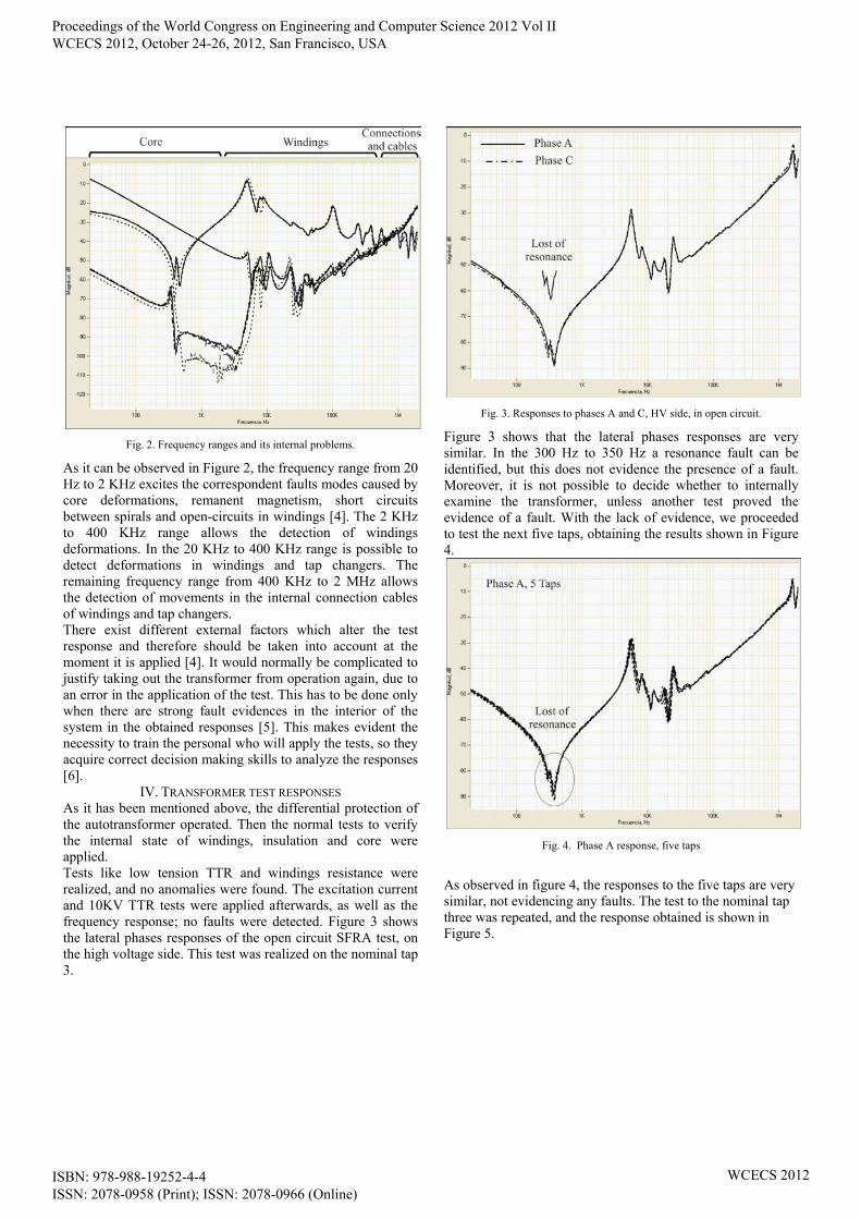
Fig. 2. Frequency ranges and its internal problems.
As it can be observed in Figure 2, the frequency range from 20 Hz to 2 KHz excites the correspondent faults modes caused by core deformations, remanent magnetism, short circuits between spirals and open-circuits in windings [4]. The 2 KHz to 400 KHz range allows the detection of windings deformations. In the 20 KHz to 400 KHz range is possible to detect deformations in windings and tap changers. The remaining frequency range from 400 KHz to 2 MHz allows the detection of movements in the internal connection cables of windings and tap changers. There exist different external factors which alter the test response and therefore should be taken into account at the moment it is applied [4]. It would normally be complicated to justify taking out the transformer from operation again, due to an error in the application of the test. This has to be done only when there are strong fault evidences in the interior of the system in the obtained responses [5]. This makes evident the necessity to train the personal who will apply the tests, so they acquire correct decision making skills to analyze the responses [6].
IV. TRANSFORMER TEST RESPONSES As it has been mentioned above, the differential protection of the autotransformer operated. Then the normal tests to verify the internal state of windings, insulation and core were applied. Tests like low tension TTR and windings resistance were realized, and no anomalies were found. The excitation current and 10KV TTR tests were applied afterwards, as well as the frequency response; no faults were detected. Figure 3 shows the lateral phases responses of the open circuit SFRA test, on the high voltage side. This test was realized on the nominal tap 3.
Fig. 3. Responses to phases A and C, HV side, in open circuit.
Figure 3 shows that the lateral phases responses are very similar. In the 300 Hz to 350 Hz a resonance fault can be identified, but this does not evidence the presence of a fault. Moreover, it is not possible to decide whether to internally examine the transformer, unless another test proved the evidence of a fault. With the lack of evidence, we proceeded to test the next five taps, obtaining the results shown in Figure 4.
Fig. 4. Phase A response, five taps
As observed in figure 4, the responses to the five taps are very similar, not evidencing any faults. The test to the nominal tap three was repeated, and the response obtained is shown in Figure 5.
Proceedings of the World Congress on Engineering and Computer Science 2012 Vol II WCECS 2012, October 24-26, 2012, San Francisco, USA
ISBN: 978-988-19252-4-4 ISSN: 2078-0958 (Print); ISSN: 2078-0966 (Online)
WCECS 2012

Fig. 5. Phase A response before and after the fault.
With the movement of the tap changer, the fault declared itself, making possible its detection, as observed in Figure 5. Figure 6 shows the responses to the three phases.
Fig. 6. Three phases response
As observed in Figure 6, phases B and C preserve their original response, concluding with the fact that the fault is present in phase A. Likewise, the low tension winding in open circuit was tested obtaining the response shown in Figure 7.
Fig. 7. Three phases response, low tension side.
As observed in Figure 7, the phase A spots the presence of the fault. At the same time, the short circuit test was applied with the response shown in Figure 8.
Fig. 8. Short circuit test
As it can be observed in Figure 8, the short-circuit test reflects an important increase in the phase A impendancy, which reflects a fake contact. Against the fault declaration, we proceeded to apply the TTR to 10 KV test, the results obtained are shown in Table 1.
Proceedings of the World Congress on Engineering and Computer Science 2012 Vol II WCECS 2012, October 24-26, 2012, San Francisco, USA
ISBN: 978-988-19252-4-4 ISSN: 2078-0958 (Print); ISSN: 2078-0966 (Online)
WCECS 2012

TABLE 1 10KV TTR TEST
As observed in Table 1, phase A presents constantly distinct values in the three windings. Subsequently, the leakage reactance test was applied, not allowing the excitation of the A and C phases. From the way the signal is injected, via phase pairs, it is understood that an open circuit has taken place involving phase A. These results are shown in Table 2.
TABLE 2
LEAKAGE REACTANCE TEST
From the last tests, we can conclude that the fault is present in the tap changer of phase A. However, as observed, the excitation of this fault proved difficult, and if it had not been excited, the consequence of energizing the autotransformer would have generated a greater damage. Finally, three tests managed to prove evidence of the presence of the fault, leaving no doubt of the decision to not energize the autotransformer and proceed to the internal inspection.
VI. CONCLUSIONS
Fault detection at the interior of the transformer fundamentally depends on whether the applied tests achieve the excitation of the points where the fault will allow spotting its existence. The incipient fault detection in transformers through SFRA testing has demonstrated its effectiveness in multiple occasions. The solid faults are normally detectable by more than one conventional and unconventional test. The fault in the tap changer from phase A was detected by the SFRA, the 10 KV TTR and the leakage reactance tests.
REFERENCES
[1] Luwendran Moodley, eTheKwini Municipality and Brian de Klerk, Sweep frequency response analysis as a diagnostic tool to detect transformer mechanical integrity, Congress The Association of Municipal Electricity Undertakings Southern Africa 2006.
[2] Nirgude, P.M.; Gunasakaran B.; Channakeshava; Rajkumar, A. D.; Singh, B.P., Frequency Response Analysis approach for condition monitoring of transformers, Electrical Insulation and Dielectric Phenomena, 2004, CEIDP appos; 04 2004 Annual Report Conference on Volumen, Issue, 17-20 Oct. 2004 Page(s): 186-189.
[3] Larry Coffeen, Charles Sweetser, Different Aspects of Frequency Response Analysis (FRA), IEEE/PES Transformers Committee Spring 2002 Meeting Vancober, B.C., Canada April 14-18, 2002.
[4] Sandra C. Flores V., “Análisis de la Respuesta a la Frecuencia en Pruebas de Campo a Transformadores de Potencia”, tesis de licenciatura, Nov. 2010.
[5] Lapworth J. A. and McGrill J.J. “Transformer Winding Movement Detection by Frequency Response Analysis (FRA)” Proceedings of the Sixty-Sixth Annual International Conference of Doble Clients, 1998, Sec 8-14.
[6] Sánchez Servando, Avalos Alberto, Pérez Carlos. “FIELD AND LABORATORY EXPERENCES IN SWEEP FREQUENCY IN TRANSFORMERS”, Doble Engineering Company- 75th Annual International Doble Client Conference, 2008.
Tap Vp Vs Nominal Relation
H1-H3
H2-H1
H3-H2
3 110000 69000 1.594 1.614 1.594 1.585
3 63508 13800 4.602 4.509 4.603 4.605
3 39837 13800 2.886 2.794 2.887 2.887
Proceedings of the World Congress on Engineering and Computer Science 2012 Vol II WCECS 2012, October 24-26, 2012, San Francisco, USA
ISBN: 978-988-19252-4-4 ISSN: 2078-0958 (Print); ISSN: 2078-0966 (Online)
WCECS 2012