inc336 level measurement - inc.kmutt.ac.thinc.kmutt.ac.th/course/inc336/level.pdf · the float...
TRANSCRIPT

LevelLevel MEASUREMENTMEASUREMENT

AGENDAAGENDA
A. A. IntroductionIntroduction
B.B. Float methodFloat method
C.C. Displacer methodDisplacer method
D.D. Hydrostatic pressure methodHydrostatic pressure method
E.E. Capacitance methodCapacitance method
G.G. Ultrasonic methodUltrasonic method
H.H. Radar methodRadar method
I.I. Laser methodLaser method
J.J. Level detectionsLevel detections

A. IntroductionA. Introduction
11.. ContinuousContinuous LiquidLiquid LevelLevel MeasurementMeasurement andand ControlControl
Level measurement technologies are made available in different vLevel measurement technologies are made available in different versions to ersions to address a wide range of measurement needs or sometimes to addresaddress a wide range of measurement needs or sometimes to address just s just one specific application. The family of level measurement systemone specific application. The family of level measurement systems can be s can be divided into 3 main groups as follows: divided into 3 main groups as follows:
แบงออกเปน 3 กลุม

2.2. PointPoint LiquidLiquid LevelLevel DetectionDetection
3.3. SolidsSolids && DryDry ProductsProducts LevelLevel CapabilityCapability
A. IntroductionA. Introduction

2.2. PointPoint LiquidLiquid LevelLevel DetectionDetection
3.3. SolidsSolids && DryDry ProductsProducts LevelLevel CapabilityCapability
A. IntroductionA. Introduction

A. IntroductionA. Introduction
General considerations in level measurement technology selectionGeneral considerations in level measurement technology selection
• Density and viscosity ความหนาแนน และความหนืด
• Chemical composition ความเปนเคมี
• Ambient temperature อุณหภูมิสภาวะแวดลอม
• Process temperature อุณหภูมิใน process
• Process pressure ความดัน
• Vapor, mist, and dust ไอ, ฝุน
• Process conductivity and dielectric constant ความนําและไมนําไฟฟา
• Vibrationการสั่นสะเทือน
• Humidity/moisture ความชื้น
• Repeatability and accuracy requirement

B. Float MethodsB. Float Methods
The level gauge consists of a float chamber, a float, and an external indicationdevice. The float chamber is basically a column with process connections tomatch those of the storage tank, reactor, drum, column or other equipmentwhere level is to be measured. These connections may be side couplings orflanges, or top and bottom flanges.
อาศัยหลักการของอารคิมิเดสที่กลาววา แรงที่ทําใหวัตถุลอยตัวอยูไดในของเหลวจะมีคาเทากับน้ําหนักของของเหลวที่ถูกแทนที่

C. DisplacersC. Displacers
The displacement method is based on the difference between the weight of the displacement body and the upward force exerted by the medium on this body (buoyancy force).
The upward force depends on the volume of displacement body, the relative density of medium, and the level of medium.
For a given volumes and relative density, the upward force will depend on only the level of the medium.
ระดับของของเหลวในภาชนะจะมีผลตอแรงที่กระทํากับลูกลอย เมื่อระดับของของเหลวเพิ่มสูงขึ้น ก็จะทําให Displacer ขยับตัวสูงขึ้น

Displacers work well with clean liquids and are accurate and adaptable to wide variations in fluid densities. Once commissioned, however, the process fluid measured must maintain its density if repeatability is required.
Mounting may be either directly into a vessel or externally mounted in a chamber.
C. DisplacersC. Displacers
Displacer ทําดวยโลหะรูปทรงกระบอกและมคีาความถวงจําเพาะแตกตางกันไประหวาง 2.95 ถึง 1.22 ทั้งนี้ขึ้นอยูกับคาความถวงจําเพาะของของเหลวที่ตองการวัดระดับเหลานั้น

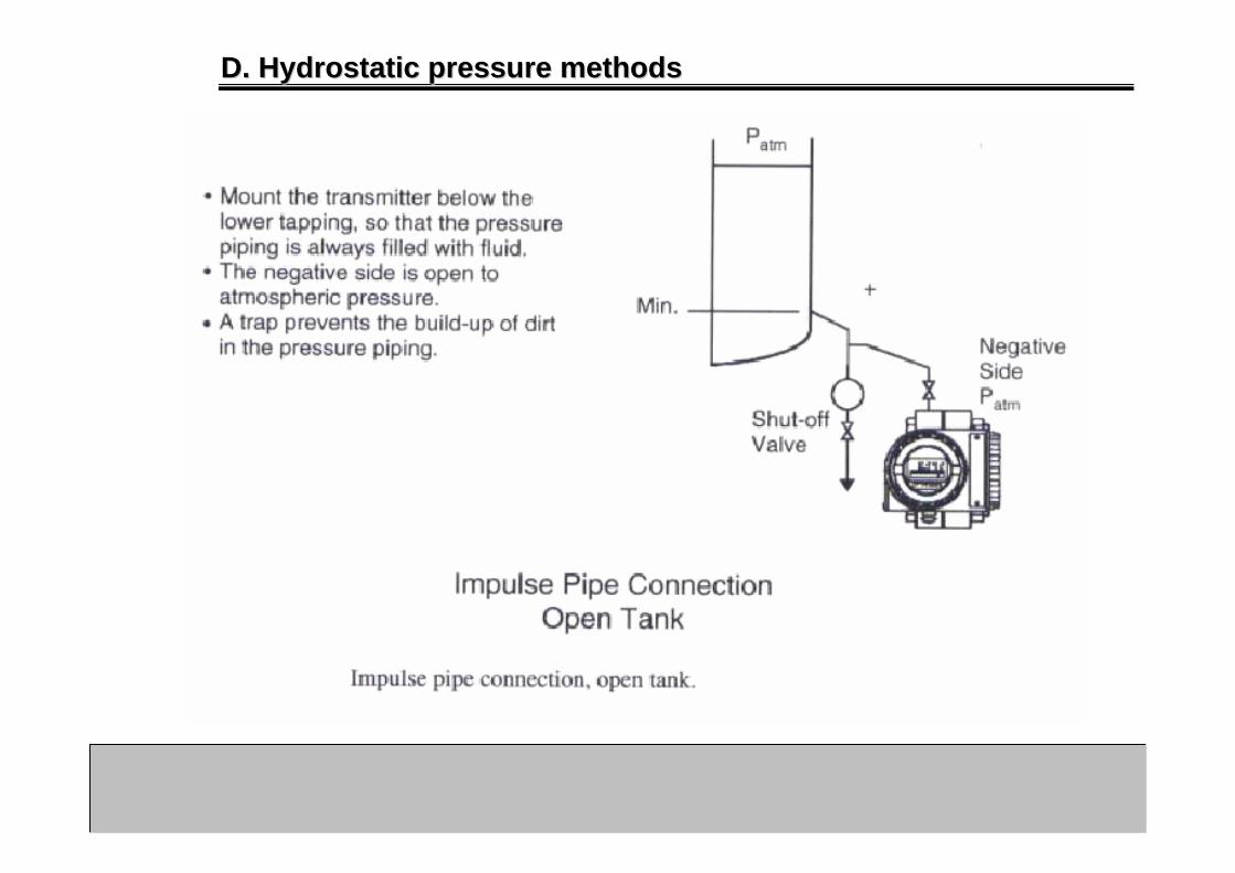
D. Hydrostatic pressure methodsD. Hydrostatic pressure methods
D.1 BubblerD.1 Bubbler
The bubbler system supplies a constant rate of airflow through a small diameter tube anchored nearthe bottom of the tank. The amount of pressurerequired to force the air bubble out of the bottomof the tube is equal to the hydrostatic pressure atthat point (i.e. the deepest point in the tank).
This is calculated using the formula
ประกอบดวยทอสงความดันลมและทอ Bubbler Bubbler ติดตั้งในแนวดิ่งในถังเปดติดตั้งในแนวดิ่งในถังเปด และที่ปลายของและที่ปลายของทอจะเปนระดับอางอิงหรือระดับศูนยทอจะเปนระดับอางอิงหรือระดับศูนย อาศัยหลักการที่วาอาศัยหลักการที่วา ความดันในทอความดันในทอ Bubbler Bubbler ที่จุมอยูที่จุมอยูในของเหลวจะมีคาเทากับความดันของของเหลวที่ปลายทอในของเหลวจะมีคาเทากับความดันของของเหลวที่ปลายทอ

D. Hydrostatic pressure methodsD. Hydrostatic pressure methods
Simplicity of design and low initial purchase cost are frequently given asadvantages of bubblers. The system consists of a pipe, an air supply, a pressure transmitter and a differential pressure regulator. The regulatorproduces the constant gas flow required to prevent calibration changes.
ถา level ต่ํา pressure ตานนอย ความดันที่วัดก็ต่ํา
ถา level สูง pressure ตานมาก ความดันที่วัดก็สูง

D. Hydrostatic pressure methodsD. Hydrostatic pressure methods
A DP is used to transmit the head pressure that thediaphragm senses due to the height of the materialin the vessel multiplied by a density variable.
The primary benefit of DP’s is that it can beexternally installed or retrofitted to an existingvessel. It can also be isolated safely from theprocess using block valves for maintenance andtesting. There are certain measurements suchas total level in separator vessels that due to widevariations in material composition of the upperphase DP is the only viable if not ideal option.
d/p cell ระบบความดันแตกตางซึ่งนิยมใชกันมากใชหลักการวัดระดับแบบใชความดันแตกตาง
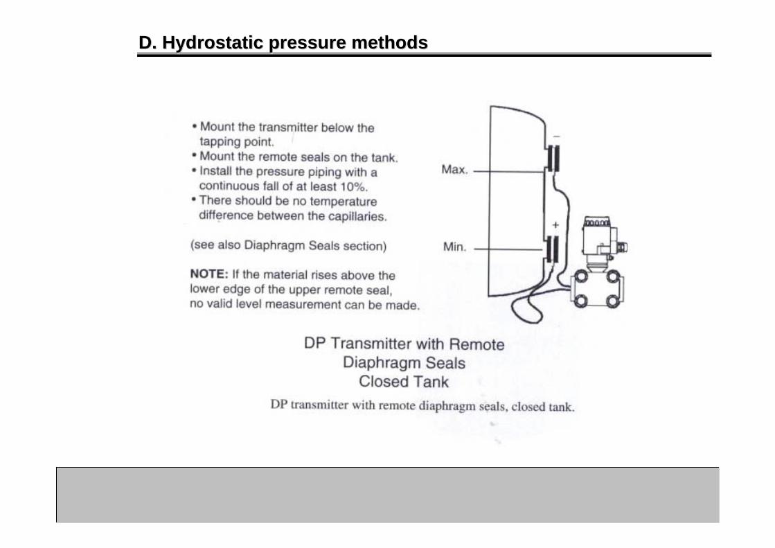
Close tank

D. Hydrostatic pressure methodsD. Hydrostatic pressure methods
DP transmitters are subject to errors due tochanges in liquid density. Density variations arecaused by temperature changes or change ofproduct.
Fluid density must be stable if readings are to beaccurate. If liquid density is subject to change a second d/p transmitter is required to measuredensity and then used to.
คาความถวงจําเพาะของของเหลวอาจมีการเปลี่ยนแปลงเมื่ออุณหภูมิเปลี่ยนแปลง ซึ่งสงผลให d/p cell วัดคาผิดพลาดได

D. Hydrostatic pressure methodsD. Hydrostatic pressure methods
D. Hydrostatic pressure methodsD. Hydrostatic pressure methods

D. Hydrostatic pressure methodsD. Hydrostatic pressure methods
กรณีถังปด ทอดาน PL อาจเปนอากาศเหนือถังหรือใสของเหลวเอาไว

D. Hydrostatic pressure methodsD. Hydrostatic pressure methods
•เวลาวัดตองคํานวณวาควรใช range ของ ΔP เทาไหร ที่
min level=> O/P ตองออก 0 % ที่ max level=> O/P ตองออก 100%
เชน ΔP = 0 – 20 psi แสดงวา ΔP = 0 => O/P ออก 4 mA
ΔP = 20 => O/P ออก 20 mA
•ถา max pressure = 100 kg/cm2 range 0-5 kg/cm2 ตองระวังไมใหความดันแตละดานเกิน 100 kg/cm2 ดวย ถึงแมวา ΔP จะไมเกิน 5 kg/cm2 ก็ตาม
Z
YX
d/p cell
Min level
PH = GsZ+GLY+Pa , PL = Pa
ΔPmin = GsZ+GLY
การคํานวณกําหนดของเหลวในถังมีความถวงจําเพาะ GL ความถวงจําเพาะในหลอด Gs
Max levelPH = GsZ+GL(Y+X)+Pa , PL = PaΔPmax = GsZ+GL(Y+X) Span = XGL, Elevation = YGL+ZGS
D. Hydrostatic pressure methodsD. Hydrostatic pressure methods

E. Capacitance methodE. Capacitance method
Capacitance is the ratio of the electric charge on one ofa pair of conductors to the potential difference betweenthe conductors.
A capacitance level probe determines the level of liquidin a column or receiver by measuring the combinedcapacitance of the liquid and gas (vapor) in the column.
ถา level เปลี่ยน คา C ก็เปลี่ยน แตไมคอยนิยมเพราะตองมีการ shield ตอ ground ใหดี เนื่องจากมีสัญญาณไฟฟามาถึงของเหลว

A. IntroductionA. Introduction
As the liquid level rises in the column, the total capacitance value increases.(The capacitance of vapor is very small compared to the capacitance of theliquid.)
This increase is measured by the controlling electronic system and an outputcontrol signal is created.
E. Capacitance methodE. Capacitance method
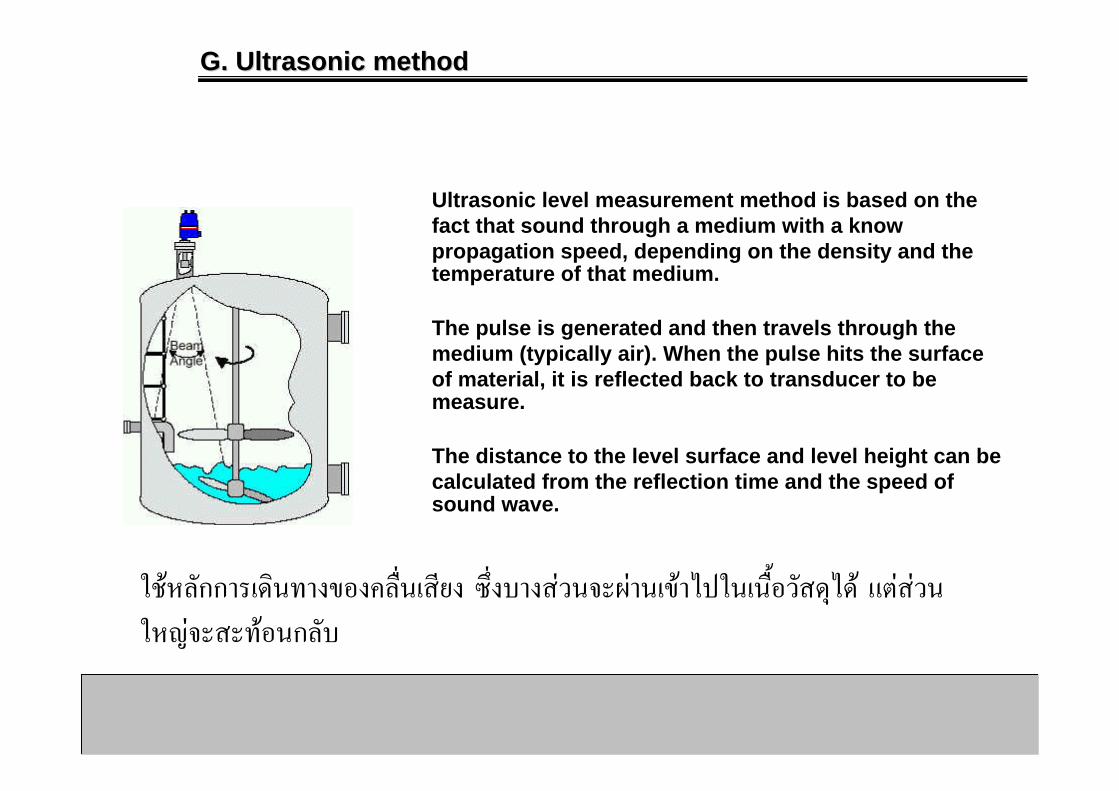
G. Ultrasonic methodG. Ultrasonic method
Ultrasonic level measurement method is based on the fact that sound through a medium with a know propagation speed, depending on the density and the temperature of that medium.
The pulse is generated and then travels through the medium (typically air). When the pulse hits the surface of material, it is reflected back to transducer to be measure.
The distance to the level surface and level height can be calculated from the reflection time and the speed of sound wave.
ใชหลักการเดินทางของคลืน่เสียง ซึ่งบางสวนจะผานเขาไปในเนื้อวัสดุได แตสวนใหญจะสะทอนกลับ

The main advantages of ultrasonic level instrumentation are that the transducer does not come into contact with the process material, they have no moving parts and a single top of vessel entry makes leaks less probable than fully wetted techniques.
There are various influences that affect the returnsignal. Things such as powders, heavy vapors, surfaceturbulence, foam and even ambient noise can affectthe returning signal.
Temperature can also be a limiting factor in manyprocess applications. Ultrasonic devices will notoperate on vacuum or high pressure applications.
G. Ultrasonic methodG. Ultrasonic method

Radar is becoming a rapidly important method for measuring the level of liquids and some case of solids. The two technologies on the market are frequency modulated continuous wave (FMCW) or pulsed wave time of flight.
Pulsed Wave systems emit a microwave burst towards the process material, this burst is reflected by the surface of the material and detected by the same sensor which now acts as a receiver. Level is inferred from the time of flight (transmission to reception) of the microwave signal.
FMCW systems, however, continuously emit a swept frequency signal and distance is inferred from the difference in frequency between the transmit and receive signals at any point in time.
H. Radar methodH. Radar method

This non-contact technology produces highly accuratemeasurements in storage tanks and some processvessels. Radar is an excellent, but fairly expensivetechnology for continuous level measurements.There are various influences that affect the returnsignal.
Things such as powders, heavy vapors, surfaceturbulence, foam and even ambient noise can affectthe returning signal.
It’s primary disadvantage is cost, which can bejustified for tank gauging and inventory control. Thepressure ratings on radar antenna are limited andthese devices cannot measure interfaces.
H. Radar methodH. Radar method

I. Laser methodI. Laser method
Advances in optical technology have reducedthe cost of laser engines to the point where ithas become practical to use infrared lasers aslevel measurement devices.
The LASERMETER measures the time it takesfor a laser pulse to travel from the instrument toa target and back. The distance to the target iscalculated from this time.
In some cases, they have become competitive inthe same range of applications as microwavelevel. They are still susceptible to attenuation ofthe beam by vapor, and other forms of beamscattering.
They have been tried on granulars and solids,with wildly varying results.

I. Laser methodI. Laser method

I. Laser methodI. Laser method
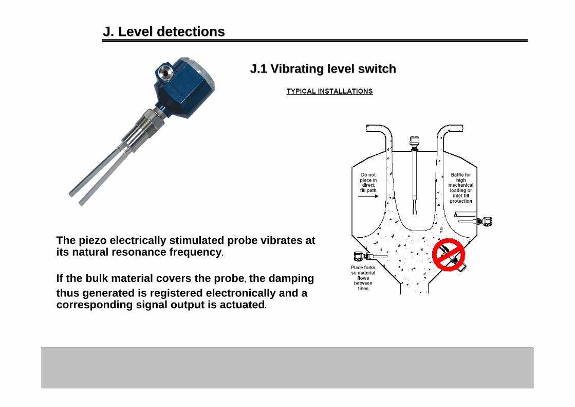
J. Level detectionsJ. Level detections
J.1 Vibrating level switchJ.1 Vibrating level switch
The piezo electrically stimulated probe vibrates atits natural resonance frequency.
If the bulk material covers the probe, the dampingthus generated is registered electronically and a corresponding signal output is actuated.

J. Level detectionsJ. Level detections
J.2 Level paddle switchJ.2 Level paddle switch
Level is detected by the change in inertia of a rotating paddle depending on whether the paddle is in the air or in contact with the product.
The location should be selected such that the product to be monitored is allowed to freely flow both into and away from the rotating paddle.
However, the paddle should not be placed directly under the free-falling path of the product.

J. Level detectionsJ. Level detections
J.4 Level conductivity switchJ.4 Level conductivity switch
This method is suitable only for level measure-ment in conductive liquids. The difference in the conductivity of partially insulated electrode is measured when the probe is covered and not covered with the conductive product.
The advantages of this method are simple, inexpensive and suitable for dual or multiple point control.
The disadvantages are probe can not become contaminated with grease or other deposits and has limited suitability for products of varying conductivity.

SUMMARYSUMMARY
Source: http://www.omega.com/literature/transactions/volume4/images/11_Table.I_l.GIF