in uence of diaphragm opening on seismic response of...
TRANSCRIPT

Scientia Iranica A (2016) 23(4), 1689{1698
Sharif University of TechnologyScientia Iranica
Transactions A: Civil Engineeringwww.scientiairanica.com
Research Note
In uence of diaphragm opening on seismic response ofrectangular RC buildings with end shear walls
A.R. Khaloo, H. Masoomi�, S. Nozhati and M. Mohamadi Dehcheshmeh
Department of Civil Engineering, Sharif University of Technology, Tehran, Iran.
Received 2 February 2014; received in revised form 20 June 2015; accepted 28 November 2015
KEYWORDSFloor diaphragm;Reinforce concretestructures;Pushover curves;In-plane exibility;Diaphragm opening.
Abstract. Routinely, behavior of oor diaphragms is assumed completely rigid in theirplane, which leads to erroneous results in analysis and design of some particular buildings.In this study, 4-story RC buildings, with end shear walls and plan aspect ratio of 3, areconsidered in order to investigate the in uence of diaphragm openings on their seismicresponse. It is concluded that although in-plane oor exibility has enormous e�ectson pre-yielding part of pushover curve, it has no in uence on post-yielding part of that.Furthermore, the opening beside shear walls has crucial impact on response of building.Hence, it would be better o� avoiding opening near the shear walls; if not, the in-plane exibility of diaphragm has not to be overlooked even if the plan aspect ratio of building is 3.© 2016 Sharif University of Technology. All rights reserved.
1. Introduction
Modeling is one of the most important steps in analysisand design of structures. Most of the time, behavior of oor diaphragms is assumed completely rigid in theirplane in order to simplify practical design. Althoughthis assumption leads to acceptable results in anal-ysis and design of conventional buildings, erroneousresults may be assessed in some particular buildings{for instance, narrow buildings with sti� end walls.Accordingly, behavior of the aforementioned buildingsin future earthquakes will oppose the performancespredicted in design phase and they are so vulnerableinasmuch as in-plane de ection of oor diaphragms isstriking, which cannot be ignored. Unexpected build-ing behaviors and even collapses, owing to neglectedin-plane exibility of diaphragm, were reported inseveral earthquakes during last decades. For instance,
*. Corresponding author. Tel.: +98 21 66164211;Fax: +98 912 1087774E-mail addresses: [email protected] (A.R. Khaloo);[email protected] (H. Masoomi);[email protected] (S. Nozhati);[email protected] (M.M. Dehcheshmeh)
during the 1994 Northridge earthquake, several parkingstructures su�ered partial or complete collapse [1-3]. Large diaphragm in-plane deformations underearthquake loading are one reasonable cause of thesefailures. Diaphragms were assumed rigid in analysisand design of these parking structures. Since storydrifts are much larger than those of shear walls dueto signi�cant exibility of the diaphragms, distributionof seismic loads was strongly di�erent from that whichwas anticipated. Therefore, gravity load system, whichwas not designed for lateral forces, experienced largedisplacement and failed, leading to the collapse of theparking structure.
According to ASCE7-10, reinforced concrete oordiaphragm in buildings with plan aspect ratio of 3:1or less is assumed rigid [4]. This assumption neglectssmall diaphragm deformations; however, it is notaccurate for cases in which the diaphragm deformationsare large enough to highly a�ect building performanceunder seismic loading. In-plane diaphragm deforma-tions are particularly signi�cant in buildings such as thelong and narrow ones and the ones with end shear walls;with setbacks in elevation; with plans in the shapes ofletters L, Y, T, to name but a few [5-7]. Moeini and
1690 A.R. Khaloo et al./Scientia Iranica, Transactions A: Civil Engineering 23 (2016) 1689{1698
Rafezi [8,9] investigated RC buildings with plans indi�erent shapes by using response-spectrum dynamicanalysis. Their study indicated that rigid diaphragmassumption is accurate enough in buildings withoutshear wall, even in asymmetric buildings. Nonetheless,this hypothesis leads to erroneous results in buildingswith shear wall, especially buildings with end shearwalls.
Al Harash et al. [10,11] studied in uence ofdiaphragm openings on buildings with three types of oor diaphragm models, namely rigid, elastic, andinelastic. The results illustrate that interior frames ab-sorb more shear when there are openings in diaphragmsince in-plane diaphragm deformation is greater inthis situation. Additionally, in these circumstances,rigid and elastic diaphragm models will result in aninaccurate estimation of the nonlinear seismic responseof building inasmuch as these models overlook yieldingin diaphragms. Thus, in long buildings with diaphragmopenings, inelastic diaphragm model should be usedin order to obtain precise results. They used modelswith lumped mass for each oor. However, assuminga lumped mass could be acceptable when we adoptrigid diaphragm in models. In this way, it seems thatinelastic behavior of slabs in analyses of the modelsused in the aforementioned study comes from thisassumption.
Therefore, in the current study, in order toinvestigate the exibility of diaphragm, masses weredistributed through the oor to show the real situation.As a simple supported beam has di�erent responsesunder a single point load and a distributed loadwith the same magnitude, diaphragms would also besensitive to applied load when they are modeled byreal in-plane sti�ness.
2. Objectives
The primary goals of the study presented here are toinvestigate the errors which appear in seismic parame-ters due to rigid diaphragm assumption and intensityof changes in these errors when there are openingsin the diaphragm. The study attempts to accentuatethe momentousness of diaphragm action on a speci�cclass of buildings. This research considers buildingswith plan aspect ratio of 3 and with end shear walls.Floor openings of di�erent sizes are located in di�erentparts of the plan in order to look into the in uence ofdiaphragm opening on seismic response and pushovercurves of such buildings.
3. Description of models
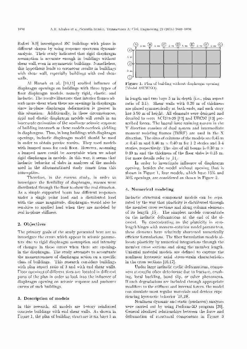
In this research, all models are 4-story reinforcedconcrete buildings with end shear walls. As shown inFigure 1, the plan of building structure is six bays 5 m
Figure 1. Plan of building without diaphragm opening(Model 4SEWNO).
in length and two bays 5 m in depth (i.e., plan aspectratio of 3:1). Shear walls with 0.20 m of thicknessare placed symmetrically at both ends, and each storyhas 3.50 m of height. All elements were designed anddetailed to meet ACI318-99 [12] and UBC97 [13] pre-scribed forces. The lateral force resisting system in theY direction consists of dual system and intermediatemoment resisting frames (IMRF) are used in the Xdirection. The sizes of columns of the models are 0.45 m� 0.45 m and 0.40 m � 0.40 m for 1-2 stories and 3-4stories, respectively. The size of all beams is 0.30 m �0.40 m and the thickness of the oor slabs is 0.15 m.For more details refer to [14].
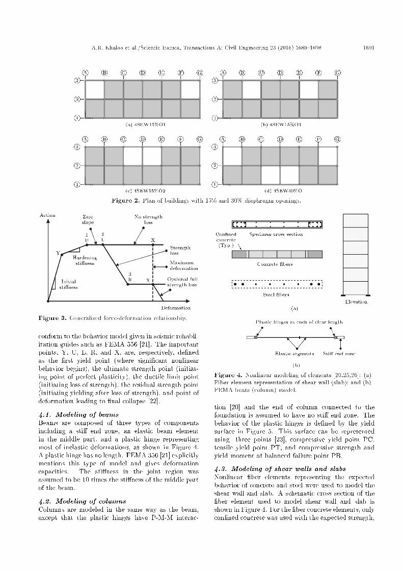
In order to investigate in uence of diaphragmopening, besides the model without opening that isshown in Figure 1, four models, which have 15% and30% openings, are considered as shown in Figure 2.
4. Numerical modeling
Inelastic structural component models can be sepa-rated by the way that plasticity is distributed throughthe member cross sections and along column elementsof its length [15]. The simplest models concentrateon the inelastic deformations at the end of the el-ement. By concentrating on the plasticity in zero-length hinges with moment-rotation model parameters,these elements have relatively shortened numericallye�cient formulations. The �ber formulation models al-locate plasticity by numerical integrations through themember cross sections and along the member length.Uniaxial material models are de�ned to capture thenonlinear hysteretic axial stress-strain characteristicsin the cross sections [16,17].
Under large inelastic cyclic deformations, compo-nent strengths often deteriorate due to fracture, crush-ing, local buckling, bond slip, or other phenomena.If such degradations are included through appropriatemodi�ers to the sti�ness and internal forces, the modelcan simulate most regular materials and devices expe-riencing hysteretic behavior [18,19].
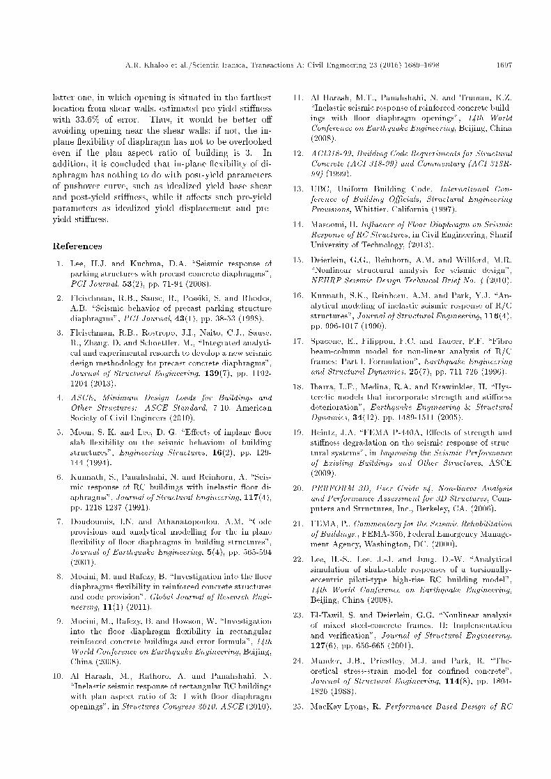
Nonlinear dynamic and static (pushover) analyseswere carried out by using Perform-3D program [20].General idealized relationships between the force anddeformation of structural components in Figure 3
A.R. Khaloo et al./Scientia Iranica, Transactions A: Civil Engineering 23 (2016) 1689{1698 1691
Figure 2. Plan of buildings with 15% and 30% diaphragm openings.
Figure 3. Generalized force-deformation relationship.
conform to the behavior model given in seismic rehabil-itation guides such as FEMA 356 [21]. The importantpoints, Y, U, L, R, and X, are, respectively, de�nedas the �rst yield point (where signi�cant nonlinearbehavior begins), the ultimate strength point (initiat-ing point of perfect plasticity), the ductile limit point(initiating loss of strength), the residual strength point(initiating yielding after loss of strength), and point ofdeformation leading to �nal collapse [22].
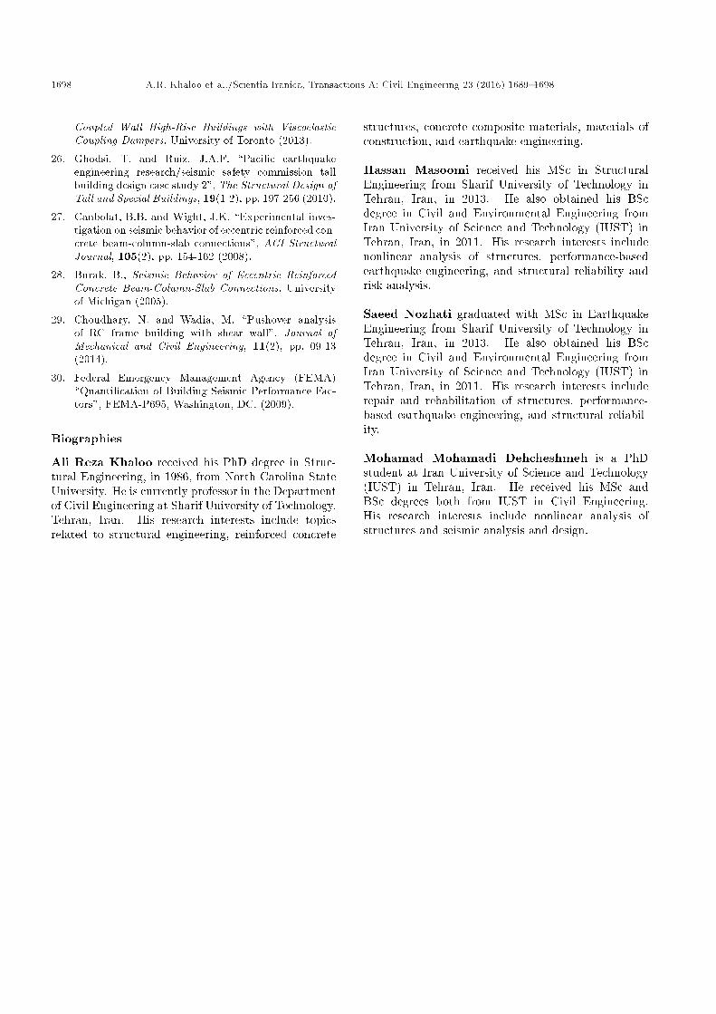
4.1. Modeling of beamsBeams are composed of three types of componentsincluding a sti� end zone, an elastic beam elementin the middle part, and a plastic hinge representingmost of inelastic deformations, as shown in Figure 4.A plastic hinge has no length. FEMA 356 [21] explicitlymentions this type of model and gives deformationcapacities. The sti�ness in the joint region wasassumed to be 10 times the sti�ness of the middle partof the beam.
4.2. Modeling of columnsColumns are modeled in the same way as the beam,except that the plastic hinges have P-M-M interac-
Figure 4. Nonlinear modeling of elements [20,25,26]: (a)Fiber element representation of shear wall (slab); and (b)FEMA beam (column) model.
tion [20] and the end of column connected to thefoundation is assumed to have no sti� end zone. Thebehavior of the plastic hinges is de�ned by the yieldsurface in Figure 5. This surface can be representedusing three points [23], compressive yield point PC,tensile yield point PT, and compressive strength andyield moment at balanced failure point PB.
4.3. Modeling of shear walls and slabsNonlinear �ber elements representing the expectedbehavior of concrete and steel were used to model theshear wall and slab. A schematic cross section of the�ber element used to model shear wall and slab isshown in Figure 4. For the �ber concrete elements, onlycon�ned concrete was used with the expected strength,

1692 A.R. Khaloo et al./Scientia Iranica, Transactions A: Civil Engineering 23 (2016) 1689{1698
Figure 5. PMM yield surface for columns.
Figure 6. Concrete stress-strain relationship.
i.e. the uncon�ned concrete cover was neglected. Theconcrete stress-strain relationship was based on themodi�ed Mander model for con�ned concrete [24],based on a nominal concrete compressive strength,f 0c, of 25 MPa and the tension strength of concretewas neglected (Figure 6). Since the used computerprogram, Perform-3D, requires the concrete stress-strain relation to be de�ned by four linear segments,four control points were selected to approximate therelation produced using the Mander model as shown inFigure 6. Both shear wall and oor slab were modelednonlinearly in their plane, and they behave linearly outof plane [25].
4.4. Cyclic degradationCyclic energy dissipation factors are shown in Tables 1and 2. Cyclic degradation of the reinforcing steelcan be accounted for by specifying energy factors.
Table 1. Cyclic degradation of beams and columns.
Points Energy factorsBeam Column
Y 0.50 1U 0.45 1L 0.40 0.90R 0.35 0.85X 0.35 0.80
Table 2. Cyclic degradation parameters of reinforcingsteel.
Strain Energy factor
DY 0.700.0025 0.680.0040 0.640.0060 0.62
DX 0.60
These factors alter the material backbone curve witheach load cycle, making it dependent on the loadinghistory. Perform-3D allows the user to de�ne therelationship between the maximum strain in a givenhysteresis loop and an associated energy factor. Energyfactors represent the ratio of the area of the degradedhysteresis loop over the area of the un-degraded loopand are typically calibrated using test data. The energyfactors used to model the reinforcing steel are the sameas those used by Ghodsi and Ruiz [26].
4.5. Beam-to-column connectionsFrom several experimental studies on seismic behaviorof reinforced concrete beam-to-column connections, itwas observed that if a deformable joint model wasnot de�ned in frame modeling, lateral drift of thestructure was underestimated [27,28]. However, in thisstudy, beam-to-column connections were neglected. Inthese circumstances, rigidity of diaphragm will beestimated conservatively, since considering beam-to-column connections causes more exible lateral loadresisting system; therefore, diaphragm would be morerigid in comparison to lateral load resisting system.Also, lateral displacements were compared in this studyin the case of rigid diaphragm assumption and exiblediaphragm. Thus, since beam-to-column connectionshave approximately the same in uence in both ofthese parameters, this negligence could be accept-able.
5. Records selection
In order to select suitable earthquake records foranalysis, di�erent codes have approximately the same

A.R. Khaloo et al./Scientia Iranica, Transactions A: Civil Engineering 23 (2016) 1689{1698 1693
recommendations. Regarding the number of accelero-grams, Eurocode 8, FEMA 450 (2003 NEHRP rec-ommended provisions), FEMA 356, and ASCE 7-05recommend that a suite of not less than three motionsshould be used for time-history analysis. Accordingto FEMA 356 Section 1.6.2.2, time-history analysisshould not be performed with fewer than three datasets of ground motion time histories. Time his-tories should have magnitude, fault distances, andsource mechanisms that are equivalent to those thatcontrol the design earthquake ground motion. Foreach data set, the Square Root of the Sum of theSquares (SRSS) of the 5%-damped spectrum of thescaled horizontal components should be constructed.The data sets should be scaled such that the aver-age value of the SRSS spectra does not fall below1.4 times the 5%-damped spectrum for the designearthquake for periods between 0.2T seconds and1.5T seconds (where T is the fundamental periodof the building) [29]. Where three time historydata sets are used in the analysis of a structure,the maximum value of each response parameter (e.g.,force in a member, displacement at a speci�c level)should be used to determine design acceptability.Where seven or more time history data sets are em-ployed, the average value of each response parametershould be permitted to determine design acceptabil-ity.
In the current investigation, three pair recordswere selected and scaled. Therefore, a series of twentytwo far-�eld quakes are selected from FEMA-p695 [30]for site class C. The three records with the most �tnessto the design response spectrum for site class C wereselected; they are tabulated in Table 3. As shown inFigure 7, these three records were scaled for use innonlinear analyses. The related scaled factors are alsomentioned in Table 3.
6. Results and discussion
Nonlinear dynamic and static analyses were conductedfor each model; the results are discussed here.
Figure 7. SRSS spectra were scaled to be greater than1.4 times the design spectrum for the periods between0.2T and 1.5T.
6.1. Pushover analysisPushover analysis was conducted for all buildings andmodels were pushed by triangular distribution overthe building height until the roof displacement met 1percent of the building height (i.e. 0.15 m). Pushovercurves are illustrated in Figure 8 in two parts, namelyrigid diaphragm and exible diaphragm. As seen inFigure 8(a), if the rigid diaphragm assumption is usedin the analysis, existence of opening in diaphragm willnot a�ect pushover curves due to the fact that in-plane exibility of diaphragm is not taken into account. Inthis situation, even if the opening is as large as 30% ofall the diaphragm area, all buildings pushover curveswill be virtually identical.
On the other hand, when in-plane exibility ofdiaphragm is considered and diaphragm is modeled toperform in its nearly actual behavior, i.e. it can bendin its plane, an increase in diaphragm opening leads todecrease in in-plane sti�ness of diaphragm, and thus itis expected that lateral displacement will be intensi�ed.As indicated in Figure 8(b), the larger the opening indiaphragm, the greater the idealized yield displacementand the lower the e�ective lateral sti�ness. Althoughthe opening of model 4SEW30%O is two times that of
Table 3. Selected records for time history analyses.
No.Earthquake
ComponentDuration PGA Signi�cant Scale
M Year Name Station (sec) (g) duration (sec) factor
1 7.1 1999 HectorMine
HectorHEC000 45.3 0.266 11.65
0.697HEC090 45.3 0.337 9.66
2 7.5 1999 Kocaeli,Turkey
ArcelikARC000 30 0.219 11.015
1.073ARC090 30 0.15 10.275
3 6.6 1971 SanFernando
LA-HollywoodStor
PEL090 28 0.21 10.490.774
PEL180 28 0.174 11.16

1694 A.R. Khaloo et al./Scientia Iranica, Transactions A: Civil Engineering 23 (2016) 1689{1698
Figure 8. Buildings pushover curves with and without rigid diaphragm assumption: (a) Rigid diaphragm; and (b) exiblediaphragm.
Figure 9. Variations of (a) idealized yield displacement, and (b) pre-yield sti�ness by change in diaphragm openings inmodels with both rigid and exible diaphragms.
model 4SEW15%O1, in which the opening is locatedat both ends, near the shear walls, these two modelshave approximately similar pushover curves. In fact,besides the amount of opening, its location has a strongin uence on response of building. Furthermore, model4SEW15%O2, in which the opening is installed inthe middle of the plan of the building, has a similarpushover curve to that of the model without opening(model 4SEWNO). It is concluded that diaphragmopening has greater in uence when it is located nearshear walls instead of the middle of building plan,which is the farthest location from shear walls.
The pre-yield parts of idealized pushover curvesare di�erent in models with exible diaphragm andwith rigid diaphragm. Considering the same dis-placement of middle frame in both exible and rigidmodels, in the model with rigid diaphragm, all frameshave identical displacements; however, displacement inmiddle frame is greater than those in other framesof the model with exible diaphragm. Hence, therigid diaphragm assumption forces the building toclaim more base-shear in order to reach a certaindisplacement; in other words, the building respondsin a sti�er manner. With this in mind, since yieldbase shear has the same value in both models with andwithout rigid diaphragm assumption, the building with
rigid diaphragm reaches the yield base shear at lowerdisplacement value. As shown in Figure 9, althoughidealized yield displacement and pre-yield sti�ness havenothing to do with diaphragm opening in the conditionof rigid diaphragm assumption, they will have di�erentvalues by increase in opening of diaphragm in modelswith exible diaphragm. Moreover, rigid diaphragmassumption gives rise to underestimation of idealizedyield displacement and overestimation of pre-yieldsti�ness.
The post-yield parts of idealized pushover curvesare virtually identical in all models whether with exible diaphragm or with rigid diaphragm. From thepushover analysis, it is observed that in all buildings,shear walls are the �rst elements which yield andcolumns start yielding after the yielding of some beams.Nonetheless, all slab elements remain in elastic regionuntil very large drift. In this regard, after the yieldingpoint, decrease in sti�ness of lateral load resistingsystem leads to much more increasing displacementrate, and in-plane deformation of diaphragm remainsconstant or decreases after shear walls yield. Thus,slabs respond in a sti�er manner than lateral loadresisting system and their behavior approaches rigiddiaphragm behavior. It is concluded that rigid di-aphragm assumption or in-plane exibility of oor

A.R. Khaloo et al./Scientia Iranica, Transactions A: Civil Engineering 23 (2016) 1689{1698 1695
Figure 10. Variation of idealized yield base shear and post-yield sti�ness by change in diaphragm openings in modelswith both (a) rigid diaphragm, and (b) exible diaphragms.
Table 4. Pushover parameters in both exible and rigid models, and the error resulting from rigid diaphragm assumption.
Parameter4SEWNO 4SEW15%O1 4SEW15%O2 4SEW15%O3 4SEW30%O
Flex. Rigid Err.%
Flex. Rigid Err.%
Flex. Rigid Err.%
Flex. Rigid Err.%
Flex. Rigid Err.%
Idealized yield
base shear (Vy)1585.4 1580.3 0.3 1571.7 1560.4 0.7 1569.9 1567.5 0.1 1576.3 1567.8 0.5 1558.5 1552.3 0.4
Idealized yield
displacement (�y)0.0024 0.0018 25.0 0.0027 0.0018 35.2 0.0024 0.0018 25.3 0.0025 0.0018 28.7 0.0028 0.0018 37.2
Pre-yield
sti�ness476.6 633.1 32.8 412.7 632.4 53.2 474.7 634.3 33.6 454.7 634.1 39.4 398.2 631.6 58.6
Post-yield
sti�ness26.2 25.7 2.0 25.6 25.4 0.7 26.4 25.5 3.3 25.9 25.5 1.4 25.5 24.7 3.2
diaphragm has no e�ect on post-yield part of pushovercurve and, as indicated in Figure 10, idealized yieldbase shear and post-yield sti�ness not only do notchange models with di�erent opening positions andsizes, but also have the same value in both rigid and exible diaphragm models.
The summary of the pushover analysis results forall the cases is given in Table 4. Also, the errors ofpushover results due to the rigid diaphragm assumptionare calculated. As shown in the tables, idealized yieldbase shear and post-yield sti�ness have the same valuein exible and rigid models. Moreover, it is clear thatconsidering diaphragm as rigid causes high error incalculating idealized yield displacement and pre-yieldsti�ness. For instance, the errors of these parameters inmodel 4SEW30%O are 37.2% and 58.6%, respectively.
6.2. Dynamic analysisInelastic dynamic analyses were conducted for all build-ings and seismic responses of buildings were studied.Maximum roof displacements of all models with andwithout rigid diaphragm assumption are illustratedin Figure 11. In models with exible diaphragm,middle frames have greater displacement than thatof the frames which include shear wall, while dis-placements are approximately equal for all frames in
rigid diaphragm models. As indicated in Figure 11,roof displacement of model 4SEW30%O is virtuallyidentical to that of model 4SEW15%O1 with openinglocated near the shear walls; the former, however, hastwo times the opening of the latter. Moreover, model4SEW15%O2 with opening situated in the middle ofplan of the building has identical roof displacementto that of model 4SEWNO (model without opening).Indeed, in addition to the size of opening, its locationin building plan has enormous e�ect on response ofbuilding. As mentioned before, it is concluded thatdiaphragm opening has greater in uence when it islocated near shear walls.
As shown in Figure 11(b), enlargement in open-ing increases lateral displacement; nevertheless, Fig-ure 11(a) opposes this fact by showing that model4SEW30%O has lower displacement than model4SEWNO when diaphragm is assumed rigid. Eventhough most of the rigid models have similar roof dis-placements, an inaccuracy occurs in response of model4SEW30%O with rigid diaphragm. This miscalculationis because of rigid diaphragm assumption.
Diaphragm opening increases building lateral dis-placement and diaphragm in-plane deformation. Fig-ure 12 shows roof displacement in models 4SEWNOand 4SEW30%O. Middle frame displacements are

1696 A.R. Khaloo et al./Scientia Iranica, Transactions A: Civil Engineering 23 (2016) 1689{1698
Figure 11. Maximum roof displacement with and without rigid diaphragm assumption: (a) Idealized yield base shear;and (b) post-yield sti�ness.
Table 5. Maximum lateral displacement and in-plane deformation of diaphragm in both exible and rigid models, and theerror resulting from rigid diaphragm assumption.
Parameter Story4SEWNO 4SEW15%O1 4SEW15%O2 4SEW15%O3 4SEW30%O
Flex. Rigid Error%
Flex. Rigid Error%
Flex. Rigid Error%
Flex. Rigid Error%
Flex. Rigid Error%
Maximumlateral
displacement
4 4.2 3 27.2 4.6 2.8 39.6 4.2 2.9 31 4.5 2.9 35.8 4.6 2.6 42.93 3.3 2.2 31.8 3.7 2.1 44.3 3.2 2.1 33.1 3.4 2.1 38.2 3.6 1.9 47.12 2 1.4 32.7 2.2 1.3 43.5 2.1 1.3 37 2.2 1.3 41.9 2.3 1.2 49.21 0.9 0.5 42.4 1.1 0.5 52.8 1 0.5 47.2 1 0.5 50.9 1 0.5 54.3
Maximumin-plane
deformationof diaphragm
4 1.11 0 - 1.77 0 - 1.14 0 - 1.37 0 - 1.94 0 -3 1 0 - 1.6 0 - 1.17 0 - 1.38 0 - 1.74 0 -2 0.89 0 - 1.19 0 - 1.04 0 - 1.16 0 - 1.22 0 -1 0.6 0 - 0.7 0 - 0.58 0 - 0.62 0 - 0.64 0 -
Figure 12. Maximum roof displacement in models4SEWNO and 4SEW30%O with and without rigiddiaphragm assumptions.
0.03 m and 0.026 m, respectively, in models 4SEWNOand 4SEW30%O with rigid diaphragm, but they are0.042 m and 0.046 m in models with exible diaphragm.The error resulting from negligence is 27% in the modelwithout opening and 43% in the model with thirtypercent opening.
Diaphragm in-plane deformation is greater in roofdiaphragm than other stories, and it is raised by
expansion of opening. Table 5 gives maximum lateraldisplacement and maximum in-plane deformation ofdiaphragm in all stories of all models and indicate theerror in computing these parameters due to diaphragmin-plane exibility negligence.
7. Conclusion
Rigid diaphragm assumption is conventional in analysisand design of buildings. However, this hypothesis is notvalid in such cases as narrow and long buildings, and itbecomes worse if there are huge openings in diaphragmbecause of architectural purpose or stairs, to namebut two. By increase in diaphragm opening, in-plane exibility of oor diaphragm will increase, which causeshigh errors in seismic response of building and pushoverresults in the situation of rigid diaphragm assumption;for example, pre-yield sti�ness is assessed in model4SEW30%O by 58.6% of error. Additionally, besidesthe largeness of opening, its location has enormousin uence on response of building; indeed, openingsnear the shear walls have stronger e�ect and lead tomore in-plane exibility of diaphragm. For instance,although models 4SEW15%O1 and 4SEW15%O2 haveequal openings, analysis of the former model, in whichopening is located near the shear wall, assessed pre-yield sti�ness with 53.2% of error and analysis of the
A.R. Khaloo et al./Scientia Iranica, Transactions A: Civil Engineering 23 (2016) 1689{1698 1697
latter one, in which opening is situated in the farthestlocation from shear walls, estimated pre-yield sti�nesswith 33.6% of error. Thus, it would be better o�avoiding opening near the shear walls; if not, the in-plane exibility of diaphragm has not to be overlookedeven if the plan aspect ratio of building is 3. Inaddition, it is concluded that in-plane exibility of di-aphragm has nothing to do with post-yield parametersof pushover curve, such as idealized yield base shearand post-yield sti�ness, while it a�ects such pre-yieldparameters as idealized yield displacement and pre-yield sti�ness.
References
1. Lee, H.J. and Kuchma, D.A. \Seismic response ofparking structures with precast concrete diaphragms",PCI Journal, 53(2), pp. 71-94 (2008).
2. Fleischman, R.B., Sause, R., Pessiki, S. and Rhodes,A.B. \Seismic behavior of precast parking structurediaphragms", PCI Journal, 43(1), pp. 38-53 (1998).
3. Fleischman, R.B., Restrepo, J.I., Naito, C.J., Sause,R., Zhang, D. and Schoettler, M., \Integrated analyti-cal and experimental research to develop a new seismicdesign methodology for precast concrete diaphragms",Journal of Structural Engineering, 139(7), pp. 1192-1204 (2013).
4. ASCE, Minimum Design Loads for Buildings andOther Structures: ASCE Standard, 7-10. AmericanSociety of Civil Engineers (2010).
5. Moon, S.-K. and Lee, D.-G. \E�ects of inplane oorslab exibility on the seismic behaviour of buildingstructures", Engineering Structures, 16(2), pp. 129-144 (1994).
6. Kunnath, S., Panahshahi, N. and Reinhorn, A. \Seis-mic response of RC buildings with inelastic oor di-aphragms", Journal of Structural Engineering, 117(4),pp. 1218-1237 (1991).
7. Doudoumis, I.N. and Athanatopoulou, A.M. \Codeprovisions and analytical modelling for the in-plane exibility of oor diaphragms in building structures",Journal of Earthquake Engineering, 5(4), pp. 565-594(2001).
8. Moeini, M. and Rafezy, B. \Investigation into the oordiaphragms exibility in reinforced concrete structuresand code provision", Global Journal of Research Engi-neering, 11(1) (2011).
9. Moeini, M., Rafezy, B. and Howson, W. \Investigationinto the oor diaphragm exibility in rectangularreinforced concrete buildings and error formula", 14thWorld Conference on Earthquake Engineering, Beijing,China (2008).
10. Al Harash, M., Rathore, A. and Panahshahi, N.\Inelastic seismic response of rectangular RC buildingswith plan aspect ratio of 3: 1 with oor diaphragmopenings", in Structures Congress 2010, ASCE (2010).
11. Al Harash, M.T., Panahshahi, N. and Truman, K.Z.\Inelastic seismic response of reinforced concrete build-ings with oor diaphragm openings", 14th WorldConference on Earthquake Engineering, Beijing, China(2008).
12. ACI318-99, Building Code Requeriments for StructuralConcrete (ACI 318-99) and Commentary (ACI 318R-99) (1999).
13. UBC, Uniform Building Code, International Con-ference of Building O�cials, Structural EngineeringProvisions, Whittier, California (1997).
14. Masoomi, H. In uence of Floor Diaphragm on SeismicResponse of RC Structures, in Civil Engineering, SharifUniversity of Technology, (2013).
15. Deierlein, G.G., Reinhorn, A.M. and Willford, M.R.\Nonlinear structural analysis for seismic design",NEHRP Seismic Design Technical Brief No. 4 (2010).
16. Kunnath, S.K., Reinhorn, A.M. and Park, Y.J. \An-alytical modeling of inelastic seismic response of R/Cstructures", Journal of Structural Engineering, 116(4),pp. 996-1017 (1990).
17. Spacone, E., Filippou, F.C. and Taucer, F.F. \Fibrebeam-column model for non-linear analysis of R/Cframes: Part I. Formulation", Earthquake Engineeringand Structural Dynamics, 25(7), pp. 711-726 (1996).
18. Ibarra, L.F., Medina, R.A. and Krawinkler, H. \Hys-teretic models that incorporate strength and sti�nessdeterioration", Earthquake Engineering & StructuralDynamics, 34(12), pp. 1489-1511 (2005).
19. Heintz, J.A. \FEMA P-440A, E�ects of strength andsti�ness degradation on the seismic response of struc-tural systems", in Improving the Seismic Performanceof Existing Buildings and Other Structures, ASCE(2009).
20. PERFORM 3D, User Guide v4, Non-linear Analysisand Performance Assessment for 3D Structures, Com-puters and Structures, Inc., Berkeley, CA. (2006).
21. FEMA, P., Commentary for the Seismic Rehabilitationof Buildings., FEMA-356, Federal Emergency Manage-ment Agency, Washington, DC, (2000).
22. Lee, H.-S., Lee, J.-J. and Jung, D.-W. \Analyticalsimulation of shake-table responses of a torsionally-eccentric piloti-type high-rise RC building model",14th World Conference on Earthquake Engineering,Beijing, China (2008).
23. El-Tawil, S. and Deierlein, G.G. \Nonlinear analysisof mixed steel-concrete frames. II: Implementationand veri�cation", Journal of Structural Engineering,127(6), pp. 656-665 (2001).
24. Mander, J.B., Priestley, M.J. and Park, R. \The-oretical stress-strain model for con�ned concrete",Journal of Structural Engineering, 114(8), pp. 1804-1826 (1988).
25. MacKay-Lyons, R. Performance-Based Design of RC
1698 A.R. Khaloo et al./Scientia Iranica, Transactions A: Civil Engineering 23 (2016) 1689{1698
Coupled Wall High-Rise Buildings with ViscoelasticCoupling Dampers, University of Toronto (2013).
26. Ghodsi, T. and Ruiz, J.A.F. \Paci�c earthquakeengineering research/seismic safety commission tallbuilding design case study 2", The Structural Design ofTall and Special Buildings, 19(1-2), pp. 197-256 (2010).
27. Canbolat, B.B. and Wight, J.K. \Experimental inves-tigation on seismic behavior of eccentric reinforced con-crete beam-column-slab connections", ACI StructuralJournal, 105(2), pp. 154-162 (2008).
28. Burak, B., Seismic Behavior of Eccentric ReinforcedConcrete Beam-Column-Slab Connections, Universityof Michigan (2005).
29. Choudhary, N. and Wadia, M. \Pushover analysisof RC frame building with shear wall", Journal ofMechanical and Civil Engineering, 11(2), pp. 09-13(2014).
30. Federal Emergency Management Agency (FEMA)\Quanti�cation of Building Seismic Performance Fac-tors", FEMA-P695, Washington, DC. (2009).
Biographies
Ali Reza Khaloo received his PhD degree in Struc-tural Engineering, in 1986, from North Carolina StateUniversity. He is currently professor in the Departmentof Civil Engineering at Sharif University of Technology,Tehran, Iran. His research interests include topicsrelated to structural engineering, reinforced concrete
structures, concrete composite materials, materials ofconstruction, and earthquake engineering.
Hassan Masoomi received his MSc in StructuralEngineering from Sharif University of Technology inTehran, Iran, in 2013. He also obtained his BScdegree in Civil and Environmental Engineering fromIran University of Science and Technology (IUST) inTehran, Iran, in 2011. His research interests includenonlinear analysis of structures, performance-basedearthquake engineering, and structural reliability andrisk analysis.
Saeed Nozhati graduated with MSc in EarthquakeEngineering from Sharif University of Technology inTehran, Iran, in 2013. He also obtained his BScdegree in Civil and Environmental Engineering fromIran University of Science and Technology (IUST) inTehran, Iran, in 2011. His research interests includerepair and rehabilitation of structures, performance-based earthquake engineering, and structural reliabil-ity.
Mohamad Mohamadi Dehcheshmeh is a PhDstudent at Iran University of Science and Technology(IUST) in Tehran, Iran. He received his MSc andBSc degrees both from IUST in Civil Engineering.His research interests include nonlinear analysis ofstructures and seismic analysis and design.