in situ measurement equipment - apageo · in situ measurement equipment ... system a self–bored...
TRANSCRIPT
IN SITU MEASUREMENT EQUIPMENT
P.29 GEOBOX® CENTRAL UNIT FOR SOIL INVESTIGATION
P.30 GEOPAC® AUTO CONTROLLED PRESSUREMETER 5 OR 10 MPA
P.31 HYPERPAC® AUTO CONTROLLED HIGH PRESSURE PRESSUREMETER 25 OR 50 MPA
P.32 MÉNARD PRESSUREMETER AND GEOSPAD®2 UNIT FOR DATA ACQUISITION
P.37 PRESSUMETER BASIC PACKAGE
P.40 PRESSUREMETER ACCESSORIES AND SPARE PARTS
P.56 TOOLS PACKAGES
P.58 STAF® SYSTEM A SELF–BORED TUBE SYSTEM FOR PRESSUREMETER TEST
P.62 OTHER IN SITU METHOD MINI PRESSUREMETER, PHICOMETER - IN SITU SHEAR TEST,
LUGEOTEST® - LUGEON PERMEABILITY TEST, LIGHT DYNAMIC PENETROMETER, BENKELMAN BEAM, NON DESTRUCTIVE TESTING
P.68 GEOVISION® SOFTWARE GEOTECHNICAL DATA PROCESSING SOFTWARE
28

29
// I
N S
ITU
ME
AS
UR
EM
EN
T E
QU
IPM
EN
T
29
GEOBOX®
CENTRAL UNIT FOR SOIL INVESTIGATION
Ref: N7_5900900
THE +
+ Sturdy: reinforced to endure falling impact
+ IP 67: totally protected against dust and water
+ Ergonomic and handy
+ Bigger touchable screen
+ Faster processor
GeoBOX® is the central unit for monitoring and data acquisition of all your geotechnical works: piloting tests, displaying real time information on soil and recording data. Wireless, GeoBOX® is connected by WIFI with the different geotechnical equipments. Thus, you can manage several works with a single interface, according to your soil investigation needs.
Data can be directly processed on our geotechnical software GeoVision® through a USB key or GPRS transfer
NEW
MODEL !
APPLICATIONS
Pressuremeter data acquisition with GeoSPAD®2 (working with Ménard Pressuremeter)
Pressuremeter test (test piloting and acquisition) with GeoPAC® (Auto-Controlled Pressuremeter) and HyperPAC® for High Pressure
Drilling data acquisition with ExploFOR®3
ApaDYN® , data acquisition for constant energy heavy weight dynamic cone Penetrometer
Permeability test with the LugeoTEST®
Shearing test with the Phicometer
Delivered in a hardy case + VAC adaptor
+ thermal printer and accessories
GPRSIN OPTION, INTEGRATED MODEM
ALLOWING DATA TRANSFER FROM FIELD
TO THE OFFICE
Recordings can be directly edited on GeoBOX®’s portable printer

30
F1
F2
Q W E R T Y U I P
A FS D
O
G H J K L
Z X C V B N M
.,
Esc
Tab
Ctrl Alt
Enter
Space
Del
Shift
Fn
0 1 2
6
7 8 9
3
4 5
F5
F4
F3
@! # $ % ^ & * )(
;\ : ‘’ ‘ ~ `
=- | { } [ ] > ?
GEOPAC®
AUTO CONTROLLED PRESSUREMETER
NEW ! CYCLIC TEST ACCORDING TO
THE ASTM D4719-07 STANDARD OR ACCOR-
DING TO A PROPER PROGRAMMATION
THE +
+ Piloting and data acquisition by WIFI with GeoBOX®
+ Automatic procedure from the expansion to the deflation of the probe
+ Automatic pressure lag settings
+ Perfect management of the pressure increments
+ Reliable results
+ Low consumption of gas
APPLICATIONS In situ controlled loading test performed on the wall of a borehole using a cylindrical probe that expands radially
GeoPAC® manages all the different steps of a pressuremeter test according to the ISO 22476-4 and ASTM D4719-07 standards. From the test readings (volume variation based on controlled pressure), a stress-strain curve can be obtained for the soil in the case of plane deformation.Testing enables definition of three parameters:- Ménard pressuremeter modulus (EM)- Creep pressure (Pf)- Limit pressure (Pl)
IMPLEMENTATIONThe operator enters the different parameters of the test in GeoBOX® (borehole number, depth of the test, pressure of 1st pressure stage etc…). As soon as the probe is lowered into the borehole to the required test depth, GeoBOX® can launchthe test execution. From now, GeoPAC® controls all the sequences of the whole process: standard test, pressure loss, volume loss, probes bleeding. Pressure increments and pressure lag settings are also automated. During the entire process, GeoBOX® offers a monitoring of the pending test on its screen (progression, real time view of the results, line graph etc…). At any time, theoperator can decide to stop the test from GeoBOX®.
Data can be directly processed on our geotechnical sof-tware GeoVision® through a USB key or GPRS transfer
More info on GeoBOX® page 29
5 MPa
10 MPa
Recordings can be directly edited on GeoBOX®’s portable printer
Ref: N7_5900000 Ref: N7_5900050 GeoVision®-P: N2_5910001

31
// I
N S
ITU
ME
AS
UR
EM
EN
T E
QU
IPM
EN
T
F1
F2
Q W E R T Y U I P
A FS D
O
G H J K L
Z X C V B N M
.,
Esc
Tab
Ctrl Alt
Enter
Space
Del
Shift
Fn
0 1 2
6
7 8 9
3
4 5
F5
F4
F3
@! # $ % ^ & * )(
;\ : ‘’ ‘ ~ `
=- | { } [ ] > ?
HYPERPAC®
AUTO CONTROLLED PRESSUREMETER FOR VERY HIGH PRESSURE TEST
NEW ! CYCLIC TEST ACCORDING
TO A PROPER PROGRAMMATION
THE +
+ Piloting and data acquisition by WIFI with GeoBOX®
+ Automatic procedure from the expansion to the deflation of the probe
+ Automatic adjustment of pressure increments
+ Perfect management of test pressure
+ Reliable results
APPLICATIONS In situ controlled loading test performed on the wall of a borehole in rock using a cylindrical probe that expands radially
HyperPAC® manages all the different steps of a pressuremeter test with very high pressure for very hard formations and rocks. From the test readings (volume variation based on controlled pressure), a stress-strain curve can be obtained for the soil in the case of plane deformation.Testing enables definition of three parameters: - Ménard pressuremeter modulus (EM) - Creep pressure (Pf) - Limit pressure (Pl)
IMPLEMENTATIONThe borehole is drilled by coring or percussive method, so as to minimize wall disturbance. It has to keep a cavity diameter compatible with the probe size (46 mm or 74 mm). The operator enters the different parameters of the test in GeoBOX® (borehole number, depth of the test, pressure of 1st pressure stage etc…). As soon as the probe is lowered into the borehole to the required test depth, GeoBOX® can launch the test execution. From now, HyperPAC® controls all the sequences of the whole process: standard test, pressure loss, volume loss, probes bleeding. During the entire process, GeoBOX® offers a monitoring of the pending test on its screen (progression, real time view of the results, line graph etc…). At any time, the operator can decide to stop the test from GeoBOX®.
Data can be directly processed on our geotechnical sof-tware GeoVision® through a USB key or GPRS transfer
More info on GeoBOX® page 29
25 MPa
50 MPa
Recordings can be directly edited on GeoBOX®’s portable printer
Ref: N7_5900060 GeoVision®-P: N2_5910001
INNOVATIVE AND
EXCLUSIVE

32
MÉNARDPRESSUREMETER
Ref: A1_8100302
THE +
+ Conception following the original Ménard procedures
+ Clear and easy to use control panel
+ Easy to read measurements
+ Quality tripod: stable, sturdy and easy to install
+ Simple general maintenance with special package
APPLICATIONS In situ stress controlled loading test performed
on the wall of a borehole using a cylindrical probe which can expand radially
The Ménard pressuremeter (Control Unit), plastic tubing and 3-cell probe allows to perform in situ Pressuremeter test in soils according to the ISO 22476-4 and ASTM D4719-07 standards.From the test readings (volume variation based on controlled pressure), a stress-strain curve can be obtained, in the case of plane deformation, which yields: the Ménard Pressuremeter modulus (EM), the creep pressure (Pf), the Ménard limit pressure (Pl).
IMPLEMENTATIONThe borehole is drilled so as to minimize wall disturbance and to keep a cavity diameter compatible with the probe size (63 mm or 76 mm). As soon as the probe is lowered into the borehole to the required test depth, the operator can start the test execution by pressure increments with the control unit.
Data can be processed by our software GeoVision®

33
// I
N S
ITU
ME
AS
UR
EM
EN
T E
QU
IPM
EN
T
F1
F2
Q W E R T Y U I P
A FS D
O
G H J K L
Z X C V B N M
.,
Esc
Tab
Ctrl Alt
Enter
Space
Del
Shift
Fn
0 1 2
6
7 8 9
3
4 5
F5
F4
F3
@! # $ % ^ & * )(
;\ : ‘’ ‘ ~ `
=- | { } [ ] > ?
GEOSPAD®2 DATA ACQUISITION SYSTEM FOR PRESSUREMETER
Ref: N7_5900710GeoBox®: N7_5900900GeoVision®-P: N2_5910001
THE +
+ Suitable to all kind of Ménard standard pressuremeter
+ Wifi data acquisition on GeoBOX®
+ Real time test visualization on GeoBOX®
GeoSPAD®2 allows pressuremeter data acquisition through the central unit GeoBOX®
The system is entirely integrated in the pressuremeter.
Conformed to procedure B of ISO 22476-4 and ASTM D4719-07 standards, recordings are automatically carried out after 1, 15, 30 and 60 seconds with optimized accuracy: 0,1 cm3 on the volume and 10 kPa on the pressure.
Data can be directly processed on our geotechnical sof-tware GeoVision® through a USB key or GPRS transfer
More info on GeoBOX® page 29
NEW ! CYCLIC TESTS RECORDING ACCORDING TO THE ASTM D4719-07
Recordings can be directly edited on GeoBOX®’s portable printer

3434
PRESSUREMETER MÉNARD
17
8
18
19
20
21
22
23
24
9
10
11
12
13
14
15
16
17
2
3
4
5
6

35
// I
N S
ITU
ME
AS
UR
EM
EN
T E
QU
IPM
EN
T
35
INDICE DESCRIPTION REFERENCE INDICE DESCRIPTION REFERENCE
1 Gas circuit stop valve (complete) A1 1902206 14 Protection case for timer A1 8900303
2 25/100 bar gas selection valve (complete) A1 1902207 15 Pressure lag regulator (complete) A1 8320301
3 Bleed valve for both gas and water (complete) A1 1902208 16 Fixation for lid type 3 A2 8200101
4 Inversion valve 0-10m A1 1902209 17 Main pressure regulator A1 9310403
5 25/100/60 bar water selection valve (complete) A1 1902210 18 Sight tube complete (new model) A1 8902203
6 Water circuit stop valve (complete) A1 1902211 19 Polycarbonate cover plate for sight tube A1 9801603
7 0-25 bar gauge (vertical outlet) A1 8501310 20 Quick female socket for extra gauge A1 8701802
8 0-60 bar gauge (vertical outlet) A1 8501312 21 Quick female socket for hose outlet (water and gas) A1 8701804
9 Ø 100 gauge ring A1 8500301 22 Quick female socket for Nitrogen bottle inlet A1 8701801
10 Ø 60 gauge ring A1 8500302 23 Tripod A2 8202001
11 0-250 bar gauge (vertical outlet) A1 8501324 24 Stainless steel tripod axis A2 8202003
12 Ball Fixation for GeoBOX® N7 5900222 25 Filter housing complete A1 8901602
13 Timer 1 minute A1 8900301 26 Rilsan 3x6 Pressuremeter inner black lead A1 8602011
27 Rilsan 3x6 Pressuremeter inner red lead A1 8602018
1
2
3
4
15
15
25
27
6
7
8
26
17
5
11

36
SO
IL T
YP
E
CL
AY
EY
SO
ILS
SIL
TY
SO
ILS
SA
ND
Y S
OIL
CO
AR
SE
S
OIL
SR
OC
KS
BO
RIN
G T
EC
HN
IQU
ES
SL
UD
GE
AN
D S
OF
T
SO
FT
TO
ME
DIU
M
ST
IFF
ST
IFF
AB
OV
E
WA
TE
R
TA
BL
E
BE
LO
WW
AT
ER
TA
BL
E
LO
OS
E
AB
OV
E
WA
TE
R
TA
BL
E
LO
OS
EB
EL
OW
WA
TE
RT
AB
LE
ME
DIU
M
DE
NS
E A
ND
D
EN
SE
GR
AV
EL
S,
CO
BB
LE
S
WE
AT
HE
RE
D
RO
CK
, S
OF
T
RO
CK
HA
RD
OPEN HOLE DRILLING
HA
han
d a
ug
er
--
-H
AM
han
d a
ug
er
an
d m
ud
--
-C
FA
Co
nti
nu
ou
s -
--
ST
DT
MS
lott
ed
tu
be
wit
h in
sid
e
rota
ry t
oo
l an
d
mu
d c
ircu
lati
on
CD
Co
re d
rilli
ng
--
-R
PR
ota
ry
perc
uss
ion
-P
TP
ush
ed
tu
be
--
--
--
-V
DT
Vib
ro d
riven
tu
be
--
--
--
-
FU
LL
DIS
PL
A-
CE
ME
NT
DS
TD
riven
slo
tted
tu
be
--
-
SE
LF
BO
RIN
G
VIB
RO
-ST
AF
®-
-
RO
TO
-ST
AF
®-
-S
AF
®
self
-bo
red
p
rob
e-
--
--
-
Reco
mm
en
ded
S
uit
ed
A
ccep
tab
le
- N
ot
suit
ed
GU
IDE
LIN
ES
FO
R P
RE
SS
UR
EM
ET
ER
PR
OB
E
INS
TA
LL
AT
ION
TE
CH
NIQ
UE
S

37
// I
N S
ITU
ME
AS
UR
EM
EN
T E
QU
IPM
EN
T
PRESSUREMETER PACKAGEBased on 15 meters
Quantity Description Reference
suggested
Pressure and volume Control Unit 0x25 - 0x60 – 0x100 bar A1 8100302 1
ø60mm twin probe, complete with rubber cover* A1 1406006 1
ø60mm twin probe, complete with High Pressure canvas cover A1 1406010 1
ø60mm probe protection shoe A1 1496008 1
ø60mm probe to ø22mm rod connection** A1 1456002 1
ø22mm extension rod 1,00m length - hollow ** F5 02002202 15
Twin connecting tubings - 25m length*** A1 8602014 2
Quick connection for twin tubings A1 8701811 4
Nitrogen cylinder A1 1900202 1
Complete Regulator for cylinder (with connecting tubing to CU) A1 8310400 1
Calibration steel cylinder ø66mm I.D. f J2 900006301 1 or ø60 probe and ø63 slotted casing
Metal carrying box QO 005 1
* Coaxial probes available see p.40 , Probes Ø 74 available see p.44
** Precise if other rod diameter needed
*** Other lengths and coaxial tubing available see p.45 to 47
SPARE PARTS PACKAGE
Quantity Description Reference
suggested
Rubber cover, ø60mm probe A1 1416002 5
High Pressure canvas cover, ø60mm probe A1 1416008 5
Metal cover, ø60mm probe (steel strips) A1 1416006 5
Steel canvas/rubber cover ø60mm A1 1416010 3
Membrane, ø60mm probe A1 1496006 20
O-ring, ø60mm probe A1 1496004 2
Cover ring, ø60mm probe A1 1426003 2
Membrane ring, ø60mm probe A1 1426004 2
Setting up probe stand, ø60mm A1 1496010 1
Probe thread grease A1 1902001 1
Cover mounting grease M2 0901618 1
19mm wide tape roll A1 1901804 1
28mm wide tape roll A1 1901805 1
Strap wrench A1 1900302 1
ø60mm polyurethane ring extractor A1 1496001 1
ø60mm standard ring extractor A1 1496000 1
Band clip for ø60 metal cover (steel strip) A1 1496002 2
Reparation kit for twin tubings A1 1700618 2
Connection kit for twin tubings A1 1700619 2
Probe drain tap A1 1456012 2
ø6x1/8” brass nipple for twin probe A1 1700605 4
Polycarbonate sight tube (complete) New model A1 8902203 2
Tools box for pressuremeter maintenace A1 1900300 1
*Other type available see p.43
PRESSUREMETERPACKAGES

38
PRESSUREMETERTOOLS PACKAGES
Ø 63 MM MÉNARD SLOTTED TUBE WITH Ø 44 PROBEBased on 15 meters
Quantity Description Reference
suggested
1 ø63mm Ménard slotted tube right thread* J2 101006301 1
2 Cone for ø63mm Ménard slotted tube J4 060006301 2
3 Retaining plate for ø63mm Ménard slotted tube J4 0906309 1
4 Shock absorber for ø55/63mm Ménard slotted tube J4 0906305 2
5 ø63mm Ménard slotted connection to drilling head Depend on thread 1
6 Hollow washer for ø63mm Ménard slotted tube J4 0906306 1
7 ø44mm coaxial probe, complete with High Pressure canvas cover** A1 1404420 1
ø63mm Ménard extension tube, 1,5m length right thread* J1 101006302 10
High Pressure canvas cover, ø44mm probe A1 1414412 5
Membrane (short), ø44mm probe, 210mm central cell length A1 1494405 5
membrane ring, ø44mm probe A1 1424404 2
O-ring, ø44mm probe A1 9901004 2
Cover ring, ø44mm probe A1 1424402 2
Used for sand, gravel, pebble. The implementation of the tubing required a hammering system or vibrofonçage and
extraction system. Sometimes, a pilot drilling with a smaller diameter is necessary before the implementation of the tubing
in very compact ground.
* variation: Ø55 and 75, see next page
** also exists in coaxial see p.40
12 5
674 43

39
// I
N S
ITU
ME
AS
UR
EM
EN
T E
QU
IPM
EN
T
Ø 55 MM MÉNARD SLOTTED TUBE WITH Ø 44 PROBEBased on 15 meters
Quantity Description Reference
suggested
1 ø55mm Ménard slotted tube right thread* J2 102005502 1
2 Cone for ø55mm Ménard slotted tube J4 060005501 2
3 Retaining plate for ø55mm Ménard slotted tube J4 0905504 1
4 Shock absorber, ø55/63mm Ménard slotted tube J4 0906305 2
5 ø55mm Ménard slit connection to drilling head Depending of the thread
6 Hollow washer for ø55mm Ménard slotted tube J4 0905503 1
7 ø44mm twin probe, complete with High Pressure canvas cover** A1 1404420 1
ø55mm Ménard extension tube, 1,0m length right thread J1 101005501 15
**Also available in half shell
Ø 75 MM MÉNARD SLOTTED TUBE WITH Ø 60 PROBEBased on 15 meters
Quantity Description Reference
suggested
ø75mm Ménard slotted tube right thread* J2 101007501 1
Cone for ø75mm Ménard slotted tube J4 060007501 2
Shock absorber for ø75mm Ménard slotted tube J4 090007501 2
ø75mm Ménard slit connection to drilling head Depend on thread 1
ø60mm twin probe, complete with High Pressure canvas cover** A1 1406010 1
ø75mm Ménard extension tube, 1,5m length right thread J1 101007501 15
ø75mm nipple J4 070007501 15
High Pressure canvas cover, ø60mm probe A1 1416008 5
Membrane, ø60mm probe A1 1496006 5
Membrane ring, ø60mm probe A1 1426004 2
O-ring, ø60mm probe A1 1496004 2
Cover ring, ø60mm probe A1 1426003 2
*Also exists in left thread
**Also exists in coaxial see p.42

40
PRESSUREMETERACCESSORIES
Ø 44 PROBE « AX MÉNARD » TYPE
Mark Description Reference
1 ø44mm short coaxial probe, complete with rubber cover* A1 1404416
ø44mm short coaxial probe, complete with High Pressure canvas cover A1 1404414
ø44mm short coaxial probe, complete with steel canvas cover A1 1404411
ø44mm short twin probe, complete with rubber cover A1 1404422
ø44mm short twin probe, complete with High Pressure canvas cover A1 1404420
ø44mm short twin probe, complete with steel canvas cover A1 1404419
ø44mm short probe protection shoe A1 1494408
2 ø44mm probe cover (several type available) See next page
3 ø44mm probe nut A1 1494402
4 Cover ring, ø44 mm probe A1 1424402
5 O-ring, ø44mm probe A1 9901004
6 Membrane ring, ø44mm probe A1 1424404
7 Membrane short, for 210mm central cell length, ø44 mm probe A1 1494405
8 Polyurethane cover ring for metal cover, ø44mm probe A1 1424406
9 Membrane STD long, for 370mm central cell length, ø44 mm probe A1 1494406
10 ø6x1/8” brass nipple for twin probes A1 1700605
11 ø10x1/2” stainless steel nipple, ø44mm coaxial probe A1 1700615
12 Probe drain tap A1 1456012
13 Drain nut, alone A1 1497005
*Also exist in Standard Ménard probe (long central cell).
11
13
12
1
8
7
6
5
3
9
24
10 10
41
// I
N S
ITU
ME
AS
UR
EM
EN
T E
QU
IPM
EN
T
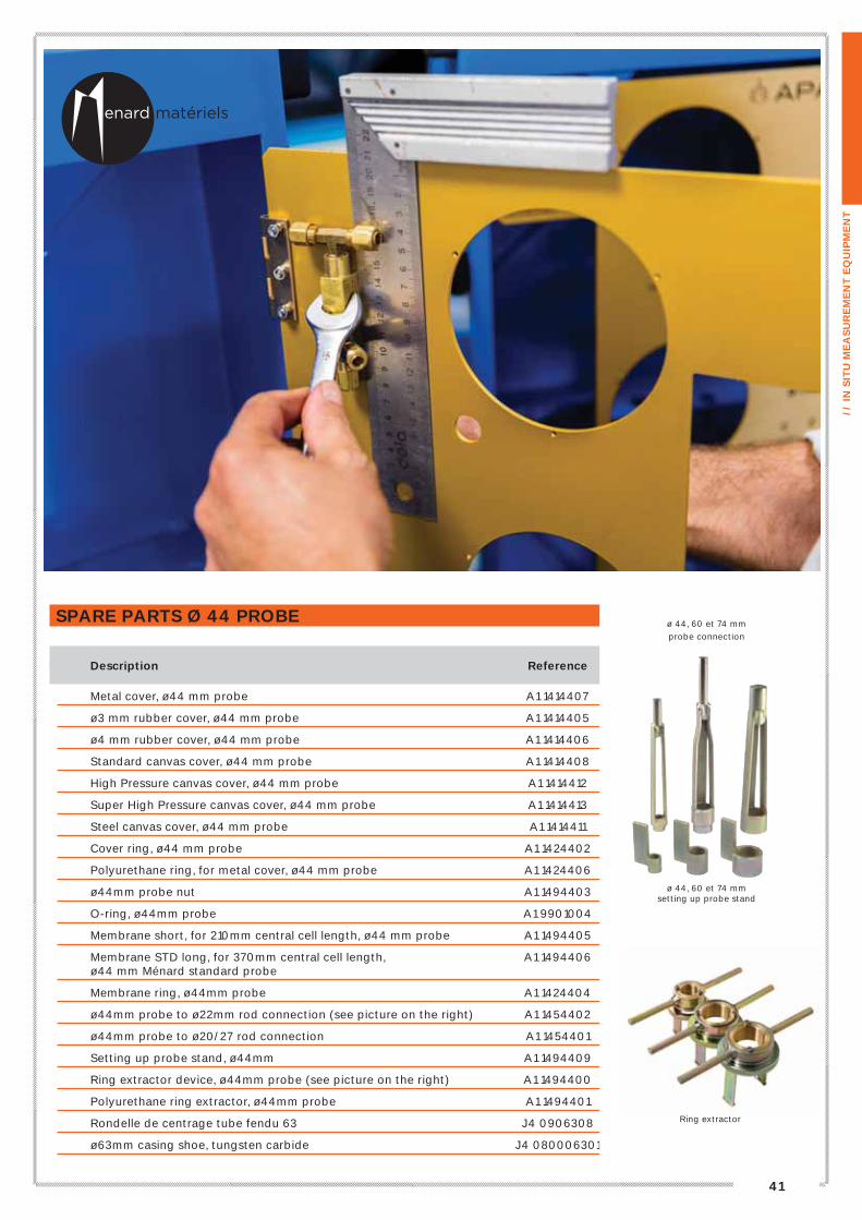
SPARE PARTS Ø 44 PROBE
Description Reference
Metal cover, ø44 mm probe A1 1414407
ø3 mm rubber cover, ø44 mm probe A1 1414405
ø4 mm rubber cover, ø44 mm probe A1 1414406
Standard canvas cover, ø44 mm probe A1 1414408
High Pressure canvas cover, ø44 mm probe A1 1414412
Super High Pressure canvas cover, ø44 mm probe A1 1414413
Steel canvas cover, ø44 mm probe A1 1414411
Cover ring, ø44 mm probe A1 1424402
Polyurethane ring, for metal cover, ø44 mm probe A1 1424406
ø44mm probe nut A1 1494403
O-ring, ø44mm probe A1 9901004
Membrane short, for 210mm central cell length, ø44 mm probe A1 1494405
Membrane STD long, for 370mm central cell length, A1 1494406 ø44 mm Ménard standard probe
Membrane ring, ø44mm probe A1 1424404
ø44mm probe to ø22mm rod connection (see picture on the right) A1 1454402
ø44mm probe to ø20/27 rod connection A1 1454401
Setting up probe stand, ø44mm A1 1494409
Ring extractor device, ø44mm probe (see picture on the right) A1 1494400
Polyurethane ring extractor, ø44mm probe A1 1494401
Rondelle de centrage tube fendu 63 J4 0906308
ø63mm casing shoe, tungsten carbide J4 080006301
ø 44, 60 et 74 mmsetting up probe stand
ø 44, 60 et 74 mm
probe connection
Ring extractor

42
PRESSUREMETERACCESSORIES
Ø 60 MM PROBE « BX MÉNARD » TYPE
Mark Description Reference
1 ø60mm twin probe, complete with High Pressure canvas cover A1 1406010
ø60mm twin probe, complete with rubber cover A1 1406006
ø60mm twin probe, complete with metal cover A1 1406008
ø60mm twin probe, complete with steel canvas cover A1 1406007
ø60mm coaxial probe, complete with metal cover A1 1406003
ø60mm coaxial probe, complete with rubber cover A1 1406002
ø60mm coaxial probe, complete with High Pressure canvas cover A1 1406011
ø60mm coaxial probe, complete with steel canvas cover A1 1406005
2 ø60mm probe protection shoe A1 1496008
3 ø60mm probe cover (several types available) See next page
4 ø60mm probe nut A1 1496003
5 Cover ring, ø60 mm probe A1 1426003
6 O-ring, ø60mm probe A1 1496004
7 Membrane ring, ø60mm probe A1 1426004
8 Membrane, 210mm central cell length, ø60 mm probe A1 1496006
9 Polyurethane cover ring for metal cover, ø60mm probe A1 1426006
10 ø6x1/8” brass nipple for twin probe A1 1700605
11 Probe drain tap A1 1456012
12 Drain nut alone A1 1497005
12
11
1
2
6
9
7
83
4
5
10

43
// I
N S
ITU
ME
AS
UR
EM
EN
T E
QU
IPM
EN
T
Ø 60 MM PROBE, SPARE PARTS
Description Reference
Metal cover (8 strips), ø60 mm probe A1 1416003
Metal cover, ø60 mm probe A1 1416006
ø3mm rubber cover, ø60 mm probe A1 1416002
ø4mm rubber cover, ø60 mm probe A1 1416005
Standard canvas cover, ø60 mm probe A1 1416007
High Pressure canvas cover, ø60 mm probe A1 1416008
Super High Pressure canvas cover, ø60 mm probe A1 1416009
Steel canvas cover, ø60 mm probe A1 1416010
Cover ring, ø60 mm probe A1 1426003
Polyurethane ring, for metal cover, ø60 mm probe A1 1426006
ø60mm probe nut A1 1496003
O-ring, ø60mm probe A1 1496004
Membrane, 210mm central cell length, ø60 mm probe A1 1496006
Membrane ring, ø60mm probe A1 1426004
ø60 mm probe protection shoe A1 1496008
ø60mm probe to ø22mm rod connection (see picture page 41) A1 1456002
ø60mm probe to ø42mm rod connection A1 1456005
ø60mm probe to ø50mm rod connection A1 1456007
ø60mm probe to Arod (pin) connection A1 1456008
ø60mm probe to R32 rod connection A1 1456011
ø60mm probe to R38 rod connection A1 1456013
Setting up probe stand, ø60mm probe (see picture page 41) A1 1496010
Probe thread grease A1 1902001
Cover mounting grease M2 0901618
Strap wrench A1 1900302
Spare strap A1 1901901
19mm wide tape roll A1 1901804
38mm wide tape roll A1 1901805
Ring extractor device, ø60mm probe A1 1496000
Polyurethane ring extractor, ø60mm probe A1 1496001
Band clip for ø60 metal cover (steel strip) A1 1496002
Probe drain tap A1 1456012
Drain nut alone A1 1497005
ø6x1/8” brass nipple for twin probe A1 1700605
COVER CHOICE ADVICE
Cover type Pressure Range Soil type
Metal cover, ø44 mm probe Medium pressure Gravel, Flinty clays, chalk Mud, soft clays, Silts, Loose sands, Pasty Chalk
3 mm rubber cover, ø44 mm probe Low pressure Mud, soft clays, Silts, Loose sands, Pasty Chalk
4 mm rubber cover, ø44 mm probe Low pressure Soft clays, Silts, Loose sands, Pasty Chalk + grain
Standard canvas cover, ø44 mm probe Medium pressure Clay, Silt, Sand
High Pressure canvas cover, ø44 mm probe Medium to High Pressure Clay, Silt, Sand + Marl, Coarse soils
Super High Pressure canvas cover, ø44 mm probe High Pressure Marl, Coarse soils, Weathered rocks, Fresh Rocks
Steel canvas cover, ø44 mm probe High Pressure Marl, Coarse soils, Weathered rocks, Fresh Rocks

44
Ø 74 MM PROBE « NX MÉNARD » TYPE
Mark Description Reference
1 ø74mm twin probe, complete with metal cover A1 1407005
ø74mm twin probe, complete with rubber cover A1 1407003
ø74mm twin probe, complete with steel canvas cover A1 1407006
ø74mm coaxial probe, complete with metal cover A1 1406999
ø74mm coaxial probe, complete with rubber cover A1 1407401
ø74mm coaxial probe, complete with steel canvas cover A1 1406998
2 ø74mm probe protection shoe A1 1497009
3 ø74mm probe cover (several type available) see below
4 ø74mm probe nut A1 1497006
5 Thick cover ring for rubber cover, ø74 mm probe A1 1427001
5 Thin cover ring for steel canvas cover, ø74 mm probe A1 1427005
6 Polyurethane cover ring for metal cover, ø74mm probe A1 1427003
7 O-ring for polyurethane cover ring, ø74mm probe A1 1497007
7 O-ring for steel cover ring, ø74mm probe A1 1497012
8 Membrane ring, ø74mm probe A1 1427002
9 Membrane, 210mm central cell length, ø74mm probe A1 1497008
Ø 74 MM PROBE, SPARE PARTS
Description Reference
Metal cover, ø74 mm probe A1 1417002
Rubber cover, ø74 mm probe A1 1417001
Steel canvas cover, ø74 mm probe A1 1417004
Thick cover ring for rubber cover, ø74 mm probe A1 1427001
Thin cover ring for steel canvas cover, ø74 mm probe A1 1427005
Polyurethane ring, ø74mm probe A1 1427003
ø74mm probe nut A1 1497006
O-ring for polyurethane ring, ø74mm probe A1 1497007
O-ring for steel ring, ø74mm probe A1 1497012
Membrane, 210mm central cell length, ø74mm probe A1 1497008
Membrane ring, ø74mm probe A1 1427002
ø74mm probe protection shoe A1 1497009
ø74mm probe to ø22mm rod connection (see picture page 41) A1 1457001
ø74mm probe to ø42mm rod connection A1 1457013
ø74mm probe to ø50mm rod connection A1 1457015
Setting up stand, ø74mm probe (see picture page 41) A1 1497010
Polyurethane ring extractor, ø74mm probe A1 1497002
2
1
3
98
4
5
7
6PRESSUREMETERACCESSORIES

45
// I
N S
ITU
ME
AS
UR
EM
EN
T E
QU
IPM
EN
T
ACCESSORIES
Mark Description Reference
1 Male coupling for twin tubing A1 8701811
2 ø6mm x 1/8’’ brass nipple A1 1700605
3 Rubber protection cap for tubing coupler A3 1901603
4 Repairing kit for twin tubing A1 1700618
5 ø6mm nut with ferrule A1 1700607
6 Straight insert 3mm diameter A1 1900602
7 Connection kit for 2 twin tubings A1 1700619
8 ø6 x 6mm brass nipple A1 1700606
TUBING
Description Reference
High Pressure Twin tubing – 25 m length A1 8602014
High Pressure Twin tubing – 33 m length A1 8602015
High Pressure Twin tubing – 50 m length A1 8602016
High Pressure Twin tubing – 100 m length A1 8602013
1
2 3
7
8
4
5
6
6
PRESSUREMETERACCESSORIES TWIN TUBING COUPLING

46
TECALAN REPAIRING KIT (COMPLETE)
Mark Description Reference
1 Repairing kit for coaxial tubing A1 9901500
2 4 parts coupling for coaxial tubing (marks 5+6+7) A1 9901499
3 Connector 4x3 A1 1601803
4 O-ring for insert coupling 4x3 / 4x4 A1 9901003
5 2 parts TECALAN coupling A1 8601801
6 ø10 mm stainless steel nut A1 9900501
7 ø10 mm ferrule High Pressure A1 9901501
TUBING
Description Reference
High Pressure coaxial tubing 100 bar TECALAN 25 m A1 8602002
High Pressure coaxial tubing 100 bar TECALAN 33 m A1 8602003
High Pressure coaxial tubing 100 bar TECALAN 50 m A1 8602004
High Pressure coaxial tubing 100 bar TECALAN 100 m A1 8602001
COAXIAL COUPLING
Mark Description Reference
1 Complete coaxial quick coupling - tubing to monitoring unit A1 8701601
2 Male plug for coaxial tubing with 6 mm tube A1 8701809
3 Male plug for coaxial tubing A1 8701808
PRESSUREMETERCOAXIAL TUBING HIGHT PRESSURE ACCESSORIES
3
2
31 2
17
2
65
4
3

47
// I
N S
ITU
ME
AS
UR
EM
EN
T E
QU
IPM
EN
T
TUBING
Description Reference
Coaxial tubing RILSAN 25 m A1 8602006
Coaxial tubing RILSAN 33 m A1 8602007
Coaxial tubing RILSAN 50 m A1 8602008
COUPLING FOR 2 COAXIAL TUBINGS RILSAN
Mark Description Reference
1 Connector 4x4 A1 1601801
2 O-ring for insert coupling A1 9901003
3 Straight connector 10 mm A1 1601805
4 ø10 mm brass nut (x2) A1 9901502
5 ø10 mm ferrule (x2) low pressure A1 9900501
Straight insert 7.5 mm A1 1600601
1
23
5
4
COUPLING KIT FOR 2 TECALANS
Mark Description Reference
1 Coupling kit A1 1601807
2 Inox inner tube A1 1602001
3 Coupling main part A1 1601806
4 ø10 mm ferrule (x2) High Pressure A1 9901501
5 ø10 mm stainless steel nut (x2) A1 9900501
2
345
1

48
PRESSUREMETERMÉNARD SLOTTED CASINGS ACCESSORIES
SLOTTED CASINGS
Description Reference
Slotted tube 46/60 right thread J2 900466002
Slotted tube 46/60 left thread J2 900466001
Slotted tube 46/60 half shell left thread J2 900466003
Slotted casing 55 mm, right thread J2 102005502
Slotted casing 55 mm, left thread J2 102005504
Slotted tube 55 Ménard half shell right thread J2 102005500
Slotted tube 55 Ménard half shell left thread J2 102005499
Reinforced slotted casing 55 mm, right thread J2 201005501
Reinforced slotted casing 55 mm, left thread J2 212005501
Slotted casing 63 mm, right thread J2 101006301
Slotted casing 63 mm, left thread J2 102006301
Slotted tube 63 Ménard half shell right thread J2 101006300
Slotted tube 63 Ménard half shell left thread J2 102005505
Reinforced slotted casing 63 mm, right thread J2 201006301
Reinforced slotted casing 63 mm, left thread J2 202006302
Slotted casing 75 mm, right thread J2 101007501
Slotted casing 75 mm, left thread J2 102007501
All our slotted tubes have 3/10 slot. They respect the effective standards (NF P 94-110-1 and ISO 22476-4)and are conform to the developer’s requirements (Louis Ménard).

49
// I
N S
ITU
ME
AS
UR
EM
EN
T E
QU
IPM
EN
T
SHORT CONES
Description Reference
Cone for slotted casing 55, right thread J4 060005501
Cone for slotted casing 55, left thread J4 060005503
Cone for slotted casing 63, right thread J4 060006301
Cone for slotted casing 63, left thread J4 060006303
Cone for slotted casing 75, right thread J4 060007501
Cone for slotted casing 75, left thread J4 060007502
Also available for reinforced slotted casings.
SLIT COUPLINGS FOR HAMMERING CASING OR MÉNARD SLOTTED CASING
Description Reference
Coupling for slotted casing 55 mm Right thread x F 42 J3 311005502
Coupling for slotted casing 55 mm Right thread x F 50 J3 111005512
Coupling for slotted casing 55 mm Left thread x F R32 J3 312005501
Coupling for slotted casing 55 mm Left thread x F R38 J3 312005503
Coupling for reinforced slotted casing 55 mm Right thread x F 42 J3 411005506
Coupling for reinforced slotted casing 55 mm Left thread x F R32 J3 412005501
Coupling for reinforced slotted casing 55 mm Left thread x F R38 J3 312005504
Coupling for slotted casing 63 mm Right thread x F 42 J3 311006304
Coupling for slotted casing 63 mm Right thread x F 50 J3 311006307
Coupling for slotted casing 63 mm Right thread x F 60 J3 311000308
Coupling for slotted casing 63 mm Left thread x F R32 J3 312006303
Coupling for slotted casing 63 mm Left thread x F R38 J3 312006305
Coupling for reinforced slotted casing 63 mm Right thread x F R38 left J3 411006300
Coupling for reinforced slotted casing 63 mm Left thread x F R32 J3 412006301
Coupling for reinforced slotted casing 63 mm Left thread x F R38 J3 312007500
Coupling for slotted casing 75 mm Right thread x F BW J3 311007500
Coupling for slotted casing 75 mm Right thread x F 50 J3 311007501
Coupling for slotted casing 75 mm Right thread x F T63 Ménard J3 311007502
Coupling for slotted casing 75 mm Left thread x F R32 J3 312007501
Coupling for slotted casing 75 mm Left thread x F R38 J3 312007502
Other threads, please consult us.
SHOCK ABSORBER, RETAINING PLATE AND HOLLOW WASHER
Description Reference
Shock absorber for 55 and 63 mm slotted casings (unit) J4 0906305
Shock absorber for 75 mm slotted casing (unit) J4 090007501
Retaining plate for 55 mm slotted casing J4 0905504
Hollow washer for 55 mm slotted casing J4 0905503
Retaining plate for 63 mm slotted casing J4 0906309
Hollow washer for 63 mm slotted casing J4 0906306
Also available for reinforced slotted casings.

50
PRESSUREMETERMÉNARD HAMMERING CASINGS ACCESSORIES
44 MÉNARD CASINGS
Description Longueur Reference
T44 Ménard casing – right thread 1,00 m K1 01004403
44 Ménard casing – right thread 1,20 m *
44 Ménard casing – right thread 1,50 m K1 010004404
44 reinforced Ménard casing – right thread 1,00 m K1 010004401
44 reinforced Ménard casing – right thread 1,20 m *
44 reinforced Ménard casing – right thread 1,50 m K1 010004402
44 reinforced nipple – right thread K1 020004401
55 MÉNARD CASINGS
Description Longueur Reference
55 Ménard casing – right thread 1,00 m J1 101005501
55 Ménard casing – right thread 1,20 m J1 201005501
55 Ménard casing – right thread 1,50 m *
55 Ménard casing – left thread 1,00 m *
55 Ménard casing – left thread 1,20 m *
55 Ménard casing – left side 1,50 m *
55 reinforced Ménard casing – right thread 1,00 m J1 101005503
55 reinforced Ménard casing – right thread 1,20 m *
55 reinforced Ménard casing – right thread 1,50 m *
55 reinforced nipple – right thread J4 070005502
55 reinforced Ménard casing – left thread 1,00 m J1 102005501
55 reinforced Ménard casing – left thread 1,20 m *
55 reinforced Ménard casing – left thread 1,50 m J1 202005501
55 reinforced nipple – left thread J4 070005501
63 MÉNARD CASINGS
Description Longueur Reference
63 Ménard casing – right thread 1,00 m *
63 Ménard casing – right thread 1,20 m J1 101006301
63 Ménard casing – right thread 1,50 m J1 101006302
63 Ménard casing – left thread 1,00 m J1 102006303
63 Ménard casing – left thread 1,20 m J1 102006301
63 Ménard casing – left thread 1,50 m J1 102006302
63 reinforced Ménard casing – right thread 1,00 m *
63 reinforced Ménard casing – right thread 1,20 m J1 201006301
63 reinforced Ménard casing – right thread 1,50 m J1 201006302
63 reinforced Ménard casing – left thread 1,00 m *
63 reinforced Ménard casing – left thread 1,20 m *
63 reinforced Ménard casing – left thread 1,50 m J2 202006301
*Please, consult us.
51
// I
N S
ITU
ME
AS
UR
EM
EN
T E
QU
IPM
EN
T
75 MÉNARD CASINGS
Description Longueur Reference
75 Ménard casing – right thread 1,50 m J1 101007501
75 Ménard casing – left thread 1,50 m J1 102007501
75 nipple – right thread J4 070007501
75 nipple – left thread J4 070007502
85 MÉNARD CASINGS
Description Longueur Reference
85 Ménard casing – right thread 1,00 m J1 101008502
85 Ménard casing – right thread 1,20 m J1 101008503
85 Ménard casing – right thread 1,50 m J1 101008504
85 Ménard casing – left thread 1,00 m *
85 Ménard casing – left thread 1,20 m J1 102008502
85 Ménard casing – left thread 1,50 m J1 102008503
CASING SHOES AND BITS
Description Reference
55 casing shoe – right thread J4 080005503
55 casing shoe – left thread J4 080005504
63 casing shoe – right thread J4 080006303
63 casing shoe – left thread J4 080006307
63 Tungsten bit – right thread J4 080006301
63 Tungsten bit –left thread J4 080006302
85 casing shoe – right thread J4 080008503
85 casing shoe – left thread J4 080008505
85 Tungsten bit – right thread J4 080008501
85 Tungsten bit – left thread J4 080008502
*Please, consult us.

52
PRESSUREMETERSPARE PARTS
PRESSURE LAG REGULATOR
Mark Description Reference
1 Pressure lag regulator with tubing A1 8320301
2 Plastic handle for front panel A1 9322202
3 Fixation Nut A1 8320501
4 ø6x1/8’’ brass nipple A1 1700605
5 O’ring for valve 2.6x1.9 A1 9321003
6 Shutter for pressure lag regulator A1 8320302
7 4 bar pressure (0.4 MPa) spring for lag regulator – up to 50 meters test A1 8321801
7 bar pressure (0.7 MPa) spring for lag regulator – up to 80 meters test A1 8321803
10 bar pressure (1 MPa) spring for lag regulator – up to 110 meters test A1 8321802
8 O’ring for pressure lag regulator screw A1 9321001
9 Pressure lag regulator screw A1 8322201
10 O’ring for stainless steel seat A1 9321002
11 Stainless steel seat A1 8321901
12 ø1/8’’x10 coupling for pressure lag regulator A1 8322220
13 Filter for pressure lag regulator A1 8320601
14 O’ring for pressuremeter filter A1 9901002
15 Reducer for filter cartridge A1 8901610
16 ø6 mm brass Ferrule A3 1901501
5 6 7 8
9
1
2
3
4
10
11
12
13
14
16
15

53
// I
N S
ITU
ME
AS
UR
EM
EN
T E
QU
IPM
EN
T
FILTER CARTRIDGE
Mark Description Reference
1 Complete filter cartridge for pressuremeter, with tubing A1 8901602
2 ø6x1/8’’ brass nipple A1 1700605
3 Filter cartridge A1 8901601
4 Protective filter for control knobs A1 9900601
5 O’ring for pressuremeter filter A1 9901002
6 Reducer for filter cartridge A1 8901610
7 ø6 mm brass Ferrule A3 1901501
MAIN REGULATOR
Mark Description Reference
1 Main regulator 100 bar (complete)* A1 9310403
2 Plastic handle for piston type regulator A1 9322203
3 ø6x1/4’’ brass tee coupling A1 1700609
4 Shutter for main regulator A1 9320301
Main regulator seal 15/100th 100 bar A1 9321602
Main regulator seal 10/100th 60 bar A1 9321601
100 bar type regulator piston alone* A1 9310400
100 bar spring for main regulator A1 9321802
10 bar spring for main regulator A1 9321801
25 bar spring for main regulator A1 9321803
40 bar spring for main regulator A1 9321804
80 bar spring for main regulator A1 9321805
*Available in 80 bar for Pressure Control Unit 60 bar, please consult us.
4
5
6
7
4
2
3
2
3
1
1

54
PRESSUREMETERSPARE PARTS
Mark Description Reference
1 Additional pressure gauge – 0 x 60 bar – ø100mm A1 8501005
2 Additional pressure gauge – 0 x 100 bar – ø100mm A1 8501002
3 Additional pressure gauge – 0 x 6 bar – ø100mm A1 8501004
4 Additional pressure gauge – 0 x 100 bar – ø60mm A1 8501003
5 Gasket for pressure gauge inlet 10 x 100 A1 8501001
6 Pressure gauge inlet connection with nut 10 x 100 A1 8500501
Pressure gauge ø. 100 – vertical inlet 10 x 100 – 0 x 25 bar A1 8501310
Pressure gauge ø. 100 – vertical inlet 10 x 100 – 0 x 60 bar A1 8501312
Pressure gauge ø. 60 – vertical inlet 10 x 100 – 0 x 250 bar A1 8501324
Mark Description Reference
1 Quick female socket for gas feeding A1 8701801
2 Quick female socket (box) for rear inlet pressure gauge (red spot) A1 8701802
3 Quick female socket (box) for gas and water outlet A1 8701804
4 Stainless steel washer for water socket A1 8201900
Quick female socket for volumeter filling A1 8701803
Quick male plug for gas feeding or volumeter filling A1 8701805
Quick male plug for rear inlet pressure gauge (red spot) A1 8701806
Quick male plug for volumeter filling A1 8701807
Inner black tubing 3 x 6 (by meter) A1 8602011
Inner red tubing 3 x 6 (by meter) A1 8602018
ø6 mm nut with ferrule A1 1700607
ø3 Straight insert A1 1900602
1
2
1
2
3
4
5
6
3
4

55
// I
N S
ITU
ME
AS
UR
EM
EN
T E
QU
IPM
EN
T
Mark Description Reference
1 Pressuremeter repairing kit (spanner+filter+seal) A1 9901007
2 Adaptor spanner for big size knobs A1 9901001
3 Shutter for main regulator A1 9320301
4 Piston regulator seal 15/100 A1 9321602
5 Protective filter for control knobs A1 9900601
6 Filter for pressure lag regulator A1 8320601
7 Male spanner 6 sides 5/64’’ for small size knobs A1 9901005
8 Male spanner 6 sides 3/32’’ for big size knobs A1 9901006
9 O’ring for valve 2.6x1. A1 9321003
10 Shutter for pressure lag regulator A1 8320302
11 Gasket for pressure gauge inlet 10x100 A1 8501001
Mark Description Reference
1 Nitrogen cylinder 1m3 A1 1900203
2 High Pressure regulator for nitrogen cylinder with tubing A1 8310400
3 High Pressure gauge 400 bar 1/4 G - new model* A1 9311309
4 Low Pressure gauge 160 bar 1/4 G - new model* A1 9311308
5 Protection for bottle regulator tubing A1 9311800
6 Tubing from gas cylinder to monitoring box A1 9311803
Piston regulator seal for bottle regulator 20/100 130 bar A1 9311601
High Pressure gauge MAV 400 bar (old model) A1 9311305
Low Pressure gauge MAV 160 bar (old model) A1 9311304
* to be mounted with aluminium gasket
Mark Description Reference
1 Polycarbonate sight tube (complete) – new model A1 8902203
2 Nylon ferrule for new type of sight tube A1 8801500
3 Polycarbonate sight tube (complete) – former model A1 8902201
4 Nylon ferrule for of sight tube (former type) A1 8801501
5 Straight insert for sight tube (former type) A1 8800601
6 Refilling bottle for Pressuremeter - 5 litres A1 9900000
Refilling funnel with quick coupling A1 9900502
Tools box for Pressuremeter maintenance A1 1900300
Elbow for polycarbonate sight tube new model A1 9801800
Bolt for sight tube new model A1 9800501
Elbow for polycarbonate sight tube former model A1 9801801
Bolt for sight tube former model A1 9900501
Polycarbonate protection plate for sight tube A1 9801603
5 4
1 3
2
1
3 4
5
6
6
1
7
9
3
1011
4 5 6
8
2
2

56
PRESSUREMETERTOOLS PACKAGES
PACKAGE FOR HAND DRILLINGBased on 10 meters
Quantity Description Reference
suggested
ø63mm hand auger x ø22mm rods thread* F5 01006302 1
ø22mm probe extension rod, hollow, 1 meter length** F5 02002202 10
Hand auger handle, for ø22mm rods F5 09002201 1
Handling wrench for ø 22mm rods F5 09000302 2
OPTION
Lifting device for 22mm rods D4 1901201 1
INJECTION OPTION
Hand injection pump see p.27 C6 0101601 1
Hand auger handle, ø22mm rods thread, with injection F5 09002202 1
* see p.72 Other diameters available.
** These rods can be used for probe implementation.
Other types available (23 square, 20x27 thread)
PACKAGE FOR DRILLING WITH CONTINUOUS FLIGHT AUGER Ø 63 MMBased on 30 meters
Quantity Description Reference
suggested
Continuous flight auger ø63x 1,50 meter length ( hexagon 21mm) F1 01006303 20
Pin for hexagon 21mm F1 04002101 25
ø63 tungsten cutting bit F1 02006301 5
ø63 auger security holder F1 04006302 1
ø63 auger fishing device F1 04006301 1
OPTION
Cardan joint hex41 box x hex21 box F1 06025003 1
Hex 21 pin x ø22 box connection (for ø22 probe extension rod) F1 05002105 1
*Other diameter available see p.73

57
// I
N S
ITU
ME
AS
UR
EM
EN
T E
QU
IPM
EN
T
PACKAGE FOR DRILLING WITH ROTARY INJECTION BIT Based on 30 meters
Quantity Description Reference
suggested
ø42mm. drilling rod 1,50 meter length K1 010004203 20
ø42mm nipple K1 020004201 22
Tricone bit 2”1/2 (63,5mm) x N ROD thread (pin) I1 040025001 1
ø42mm rods x N ROD connection (box-box) E3 031004202 1
3-way drag bit 2”1/2 (63,5mm) x A ROD thread (pin) ID 01025001 2
ø42mm rods x A ROD connection (box-box) E3 031004201 1
OPTION
Injection head hex29 x ø42mm (box-box)
* Other diameters available see p.87
** Other threads availables see p.88
PACKAGE FOR ROTARY PERCUSSION DRILLINGBased on 24 meters
Quantity Description Reference
suggested
Drilling rod R32 - 1.22m long (ø32 mm – pin-pin) H1 02003206 20
Nipple for R32 rod (box-box) H1 02003211 22
Cross bit ø64mm x Fem R32 H1 01106404 2
Button bit ø64mm x Fem R32 H1 01206401 2
Wrench for R32 rods H1 09003201 2
* Exists in retric profile see p.82

58
THE STAF® SYSTEMSELF-BORED TUBE SYSTEM FOR MÉNARD PRESSUREMETER TESTS
THE +
+ The most qualitative drilling for pressuremeter tests
+ Conformed to the STDTM specifications spelled out in the ISO 22476-4 standard
APPLICATIONS Slotted Tube technique with inside Disintegrating Tool and Mud circulation (STDTM)
THE PRINCIPLEThe drilling is realized by the eccentric tool followed by the tube column.The slotted tube is placed while drilling, avoiding borehole walls remolding.

59
// I
N S
ITU
ME
AS
UR
EM
EN
T E
QU
IPM
EN
T
IMPLEMENTATION
1. Drilling with the slotted tube and the STAF® bit according to the STDFTM method The eccentric tool drills at the bottom of the tube, followed in the meantime by the slotted tube by reducing any wall disturbance.
2. Tool retrieval The STAF® bit is pulled up with the internal drill string inside the tube, without any remolding of the borehole walls.
3. Probe positioning Thanks to the locking device, the probe is perfectly located at the central level of the steel strips forming the slotted tube. The coaxial or twin lines are protected by the string of STAF® tube from any squeezing and pinching.
4. Execution of the first pressuremeter tests The pressuremeter test is realized according to the ISO 22476-4, at the final depth
5. Next test and tubes extraction Tests start from the deepest level and then pulled up to the next level thanks to a special pulling device
Data can be directly processed on our geotechnicalsoftware GeoVision® through a USB key or GPRS transfer
THE STAF® METHOD CAN BE USED WITH ALL KIND OF GEOTECHNICAL DRILLING RIGS, EQUIPPED WITH ROTARY AND TOPHYDRAULIC HAMMER.

60
STAF®
SELF-BORED TUBE SYSTEM FOR PRESSUREMETER
STAF® CASINGBased on 20 meters
Description Reference Quantity
Guide for STAF® casing H6 0010035 1
Anvil spacer for STAF® H6 0010040 1
Slurry circulation discharge pipe H6 0010030 1
Upsetting tubing H6 0010031 2
Driving head H6 0010020 1
Casing Lg 1,22 m H6 0010010 17
Casing Lg 0.3 m H6 0010005 1
Slotted tube H6 0010000 1
Starting casing tube lg 0.3 m H6 0010015 1
Coupling box R38 x pin STAF® slotted casing H6 0010100 1
Coupling box R38 x pin STAF® casing H6 0010110 1
Manipulation loop for STAF® casing H6 0010170 1
STAF® casing spanner H6 0010175 1
Coupling pin STAF® casing x box 2’’3/8 with flats H6 0010180 1
STAF® BITSBased on 20 meters
Description Reference Quantity
Coupling box R38 x R32box modified H6 0010080 1
Rod R38 x lg 0.3 m H1 02003802 1
Rod R32 x lg 1.5 m for STAF® (x1) H6 0010073 1
Rod R32 x lg 1.22 m for STAF® H6 0010075 17
R32 nipple for STAF® H6 0010076 17
Pilot bit holder for STAF® equipment H6 0010060 1
Pilot U-pin for STAF® equipment H6 0010070 1
STAF® cross bit ø66mm H6 0010050 1
STAF® button bit ø66mm H6 0010055 1
R32 rod spanner H1 09003201 1
R32 rod spanner long handle H1 09003802 1
R38 rod spanner H1 09003803 1
ø65 rod spanner for STAF® equipment H6 0010140 1
R32 manipulation ring M5 0900010 1
Probe centering coupling
for STAF®

61
// I
N S
ITU
ME
AS
UR
EM
EN
T E
QU
IPM
EN
T
IMPLEMENTATION OF THE PRESSUREMETER PROBEBased on 20 meters
Description Reference Quantity
Coupling pin 22 x box R38 H6 0010060 1
Rod ø9 x 22mm – length 1.22 m for STAF® equipment H6 0010130 17
Coupling for 44mm probe x 22 mm rod box A1 1454402 1
ø44 mm probe centering coupling for STAF® H6 0010120 1
Wrench for ø22 mm rods F5 09000302 2
ø22 rod manipulation ring M5 0900011 1
EXTRACTION SYSTEM
Description Reference Quantity
Hydraulic Jack 15 T capacity for casing extraction H6 0010160 1
Set of hose for hydraulic jack H6 0010165 1
Foot clamp – big model M3 0100000 1
Clamp for STAF® casing M3 0200016 2
Pull up washer for STAF® system H6 0010145 1
Base plate for the hydraulic jack H6 0010150 1
STAF® is a patented technique and a registered trademark of Geomatech
EXTENSION KIT
Description Reference Quantity
Shoe casing lg 0,153 m STAF® H6 0010016 1
Short casing lg 0,152 m STAF® H6 0010018 1

62
MINI PRESSUREMETERMÉNARD PRESSUREMETER TEST
Ref: A3_1900300
THE +
+ Light and easy to handle
+ Suited for job site with difficult access (uneven and rough ground, low ceiling site...)
+ Resolution improvement for shallow depth test
DESCRIPTIONThe Mini Pressuremeter is dedicated to small diameter hand borings (with a hand auger*), in medium formation, up to 10 meters depth. Light and easy to carry, it fits especially to difficult access on site. The direct probe hammering allows performing without the need to remould the borehole walls**. Thanks to its small diameter, the intervals between 2 tests can be reduced and thus improve the test result at low depth.
MAIN EQUIPMENT
Quantity Description Reference
suggested
Pressure Volume Control 0 x 6 – 0 x 25 bar for monocell probe A3 1900300 1
Monocell ø32 mm probe A3 1901901 2
Driving cone ø32 mm probe A3 1901601 1
Probe coupling ø32 mm x F ø22 mm A3 1901801 1
25 m long tubing A7 8900100 2
Nitrogen cylinder 1m3 A1 1900202 1
High Pressure regulator at gas cylinder A1 8310400 1
Male plug – blue mark A2 8701802 1
Vaccum pump A3 1901602 1
SPARE PARTS
Quantity Description Reference
suggested
Wrench for ø22 mm rod F5 09000302 2
Extension rod ø22 mm x 1 m long F5 02002202 5
ø32 mm cover with 4 steel strips A3 1900702 5
Vulkolan ring for ø32 mm metal cover A3 1900202 2
Probe drain device A1 1456012 1
ø6 x 1/8’’ brass nipple A1 1700605 1
ø32 mm probe O-ring A3 1901001 2
19 mm wide tape roll A1 1901804 1
ø6 mm nut with ferrule A1 1700607 10
ø3 mm straight insert A1 1900602 10
*Hand auger see p.72
** Hammering of the probe with the light dynamic penetrometer using Ø 22 hollow rods, anvil and slotted hammering head for passing the tubing. see p.65
DATA CAN BE PROCEED AFTER MANUAL INPUT, BY OUR SOFTWARE GEOVISION®

63
// I
N S
ITU
ME
AS
UR
EM
EN
T E
QU
IPM
EN
T
PHICOMETERIN SITU SHEARING TEST
Ref: A7_8101601
THE +
+ Optimal test on soil hard to sampled
+ Fitted also in altered rocks
+ Fast execution and low cost compared to laboratory tests
APPLICATIONSMeasurement of the mechanical characteristics i and Ci of soil, using a linear shearing test.
IMPLEMENTATIONThe phicometer allows to perform in situ shearing test. The borehole is drilled so as to minimize wall disturbance and to keep a cavity diameter compatible with the equipment (63 mm).
The probe is lowered into the borehole to the required test depth, thanks to rods for pulling effort.
It can be used with the following equipment: - Ménard pressuremeter see p.32
- Nitrogen bottle with regulator see p.55
- Drilling rods see p.81
DATA CAN BE PROCEED AFTER MANUAL INPUT, BY OUR SOFTWARE GEOVISION®

64
LUGEOTEST®
IN SITU SOIL PERMEABILITY TESTING
Ref: A6_9900501GeoBOX®: N7_5900900 GeoVision®-L: N2_5910008
THE +
+ Wifi data acquisition on GeoBOX®
+ Real time test visualization on GeoBOX®
+ GPRS system (option)
APPLICATIONSAssess water flow potential in the soil and then detecting anomalies and fissures.
The Lugeon water test is an in situ test of formation permeability applicable to fractured rock, masonry and cohesive soil with mechanical resistance corresponding to the water pressure applied during testing.
It can be used with the following equipment: - Triplex pump, flow 100l/min, 11 bar see p.26
- Nitrogen bottle with regulator see p.55
- Packer and water level indicator see p.123
- Drilling rod for the packer manipulation see p.87
Standard version available: manual data acquisition and input in GeoVISION®
Data can be directly processed on our geotechnicalsoftware GeoVision® through a USB key or GPRS transfer
F1
F2
Q W E R T Y U I P
A FS D
O
G H J K L
Z X C V B N M
.,
Esc
Tab
Ctrl Alt
Enter
Space
Del
Shift
Fn
0 1 2
6
7 8 9
3
4 5
F5
F4
F3
@! # $ % ^ & * )(
;\ : ‘’ ‘ ~ `
=- | { } [ ] > ?
NEW

65
// I
N S
ITU
ME
AS
UR
EM
EN
T E
QU
IPM
EN
T
10
11
1
2
3
4
5
6
7
8
9
LIGHT DYNAMIC PENETROMETER, MANUAL HAMMERING
Description Reference Qty
1 Non slotted pulling connector for ø22 rod D4 1902004 1
2 Guide rod ø22 – lg 0,6 m D4 1902005 1
3 Hammer 10 kg D4 1901301 1
4 Non slotted anvil for ø 22 rod D4 1900503 1
5 Non slotted hammering head for ø 22 rod D4 1902002 1
6 Hammering rod ø22 x lg 1,0 m – marked every 10 cm F5 02002201 6
7 Lost cone holder 10 cm2 D4 1901801 1
8 Lost cone 10 cm2 with pin D4 1901603 10
8 Or hollow lost cone 10 cm2 D4 1901604 10
9 Complete lever device for ø22 rods extraction D4 1901201 1
10 Screwing and hoisting wrench for ø22 rod F5 09000302 2
11 Fixed cone 10 cm2 - ø22 rod thread D4 1901602 1
Storage box for rods D4 1903000 1
Storage box for hammering system D4 1903001 1
VARIANT FOR MINI PRESSUREMETER USE
1 Slotted pulling connector for ø22 rod D4 1902003 1
4 Slotted anvil for ø22 rod D4 1900502 1
5 Slotted hammering head for ø22 rod D4 1902001 1
6 ø22 hollow rod x lg 1,0 m F5 02002202 6
LIGHT DYNAMICPENETROMETERDYNAMIC PENETRATION TEST
Ref: D4 8101601
THE +
+ Light, compact and handy
+ Provided with transport case
DESCRIPTION
Hammering system for the control of trench or platform compaction (lost cone 10cm2) or implementation of ø32 mm probe for mini pressuremeter
DATA CAN BE PROCEED AFTER MANUAL INPUT, BY OUR SOFTWARE GEOVISION®

66
BENKELMAN BEAM1. PLATE LOADING TEST ACCORDIND TO THE
ASTM D1195 AND ASTM D1196M STANDARDS2. FLEXIBLE PAVEMENT DEFLECTION TESTING
ACCORDING TO THE ASTM D4695 STANDARD
Description Reference
High-end Benkelman beam in flight case O2 203121720
Eco Benkelman beam in box O2 203121702
Aluminum plate, diameter 600 mm 02 203121707
Manual hydraulic loading device O2 203121760
Electrical hydraulic loading device O2 203121770
Manual mechanical loading device O2 203121710
OPTION Adjustable wedge O2 203121715
The Benkelman Beam measures the deformation of a material under stress. This equipment is used for the two following test: • The plate test measures the static deformation EV1/EV2
(roads) and Westergard deformation (platforms). The Benkelman beam mesure the formation level bearing capacity by applying a load on the plate to the material with the loading device.
• Standard Benkelman Beam tests measures pavement deflection in response to a static load. Measurement is made by placing the tip of the beam between the dual tires of a loaded truck and measuring the pavement surface rebound as the truck is moved away.
MATERIALFor the deflection test, the beam is used alone.For the plate test, a loading device and aluminumplate are necessary.
BENKELMAN BEAMHigh-end modelThe Benkelman beam consists of a balance arm (in two parts) mounted on ball-bearing axis, a frame supported on the ground by three feet on height-adjustable ball-joints, with a digital dial indicator 10 mm to 0.01. The whole equipment is protected by a high resistance epoxy paint and delivered in a flight case. • Beam weight: 11.5kg • Overall length: 3m60 • Beam in storage: 29kg • L x W x H: 200 x 300 x 300 mmEco model • Beam weight: 8.5kgALUMINUM PLATE Ø 600 mmWith reinforced ribbed, side slit and handles fortransportation.
MANUAL LOADING DEVICESHydraulic model(Exists also with electrical pumps, see beside) • Hydraulic jack, force 100 kN • 203 mm Stroke with centering plate and pivot joint • Hand pump with analogue manometer 90 kN and 3.0 m
flexible hose • Wooden transport carrying case • Aluminum wedgeMechanical model • Reinforced mechanical jack, force 200 kN • Dynamometer for control, graduation from 0 to 100 kN
with loading stage • Pivot joint • Wooden transport carrying case
Mechanical loading device
ALUMINUM PLATE Ø 600 mm
Hydraulic loading device

67
// I
N S
ITU
ME
AS
UR
EM
EN
T E
QU
IPM
EN
T
NON DESTRUCTIVETESTINGS
• Sonic pulse velocity system• Ultra sonic pile testing system• Concrete reinforcement detector• Vibration reinforcement detector• Dilatometer• Crackmeter• Retractometer• Pile integrity tester• Resistivimeter• Sclerometer• Inclinometer
TDR2: PILE INTEGRITY TESTERThe TDR2 controls the integrity of piles by measuring boththe input force to a pile as well as the resulting velocity response according to ASTM D5882 standard. The software IMPRO 2 is used to transfer data, carry out basic analysis of result and produce report. Advanced simulation and impedance profiling modules are also included in this software.
AU 2000: SONIC PULSE VELOCITY SYSTEMThe AU 2000 measures pulse velocity through concrete according to the ASTM C597 and EN 14579 standards. The AU 2000 displays the received signal immediately it has passed through the material; It calculates the propagation time and the position of the signal’s point of arrival; finally it has a facility for storing the results.
SC XT 3000: ULTRA SONIC PILE TESTING SYSTEM The SC XT 2000 is designed for integrity testing of large diameter concrete piles, diaphragm walls, barettes etc… by the ultra sonic cross-hole method according to the ASTM 6760 standard. Ultra sonic transducers are used to measure the transit time of sound in concrete.
Sclerometerand many others,please consult us

68
GEOVISION®
SOFTWARE FOR GEOTECHNICAL DATA
THE +
+ Easy to use and intuitive interface
+ Personalized tables (diagraphy, graphs, reports)
+ Easy manual data input
+ Several work stations
+ Compatible with all the recent versions of Windows
For each application, manual data input allows to complete data collected in soil.
GeoVISION® is a software that enables to extract, process and format of all data coming from APAGEO data loggers. Data is inserted through a USB device, memory stick, GPRS (option) or manual input.
You can easily integrate notes, image or representative values of soil investigation.

69
// I
N S
ITU
ME
AS
UR
EM
EN
T E
QU
IPM
EN
T
PRESSUREMETER APPLICATION• Data importation and analysis• Edition of pressuremeter results (including
cyclic tests according to the ASTM D4719-07)
• Double hyperbolic method• Adjustment of the pseudo-elastic phase
DYNAMIC PROBING APPLICATION• Importation and analysis• Edition of dynamic penetration test results• Highlighting of compaction default and
conformity statement
DRILLING APPLICATION• Data importation and formatting• Edition of drilling report
LUGEON APPLICATION• Importation and calculation• Formatting and editing report for
lugeon data