in residential construction - mnlath … edition of stucco in residential construction has been...
TRANSCRIPT
A publication of the…Minnesota Lath & Plaster Bureau
“Promoting the Industry Since 1953”
Third Edition
STUCCO IN RESIDENTIAL CONSTRUCTION2007 Minnesota State Building Code Update


Steven Pedracine CSI, CDT, CEI
The Minnesota Lath and Plaster Bureau has promoted the industry since 1953. It is recognized as an education and technical spokesman for the plastering industry. It provides services to architects, the construction community and the public on a variety of matters relating to the plastering trades.
Minnesota Lath and Plaster Bureau820 Transfer RoadSt. Paul, MN 55114Phone (651) 645-0208Fax: (651) 645-0209
www.mnlath-plaster.com
©Copyright Minnesota Lath & Plaster Bureau, July 2000,Re-edited July 2004, June 2007
Third Edition
STUCCOSTUCCOIN RESIDENTIAL CONSTRUCTION2007 Minnesota State Building Code Update
i

Using This BookUsing This BookThis edition of Stucco in Residential Construction has been updated to refl ect changes in the building code and to provide commentary on research that may affect stucco installations. For your convenience, code sections have been included under boxes. Underlined parts of code sections refl ect changes that have been incorporated for this code cycle.
Another change from previous versions is in reference to weather-resistive barriers. The correct terminology is now “Water-Resistive Barriers” or you may see the acronym WRB. Also, there now is a variety of combinations and choices available in types of water-resistive barriers. This is not necessarily refl ected in all of the notes and captions of the illustrations in this handbook. For instance, you may see several illustrations that call out two layers of Grade D building paper. This terminology should be considered as interchangeable with other WRB.
DISCLAIMERThe text, drawings and related notes contained herein are typical of stucco installations in Minnesota. Please see the 2007 Minnesota State Building Code for specifi c requirements. Examples illustrated, are not called out in the code in all cases.
This guide contains general information on stucco installation and related materials. It is provided as a guide only and is not intended for any specifi c construction project. The Minnesota Lath and Plaster Bureau makes no express or implied warranty or guarantee of the techniques, construction methods, materials and details identifi ed herein, nor does it assume any liability for the use of this information.
It is the sole responsibility of any architectural or construction industry professional to apply their professional knowledge in utilizing the information contained in this publication.
Reproduction of this material is not permitted without the expressed written permission of the Minnesota Lath and Plaster Bureau.
REFERENCESReferences to ASTM C 1063-3 Standard Specifi cation for Installation of Lathing and Furring to Receive Interior and Exterior Portland Cement-Based Plaster, extracted, with permission. Copyright ASTM International, 100 Barr Harbor Drive, West Conshohocken, PA 19428. A copy of the complete standard may be obtained from ASTM, phone: (610) 832-9585, fax: (610) 832-9555, email: [email protected], website: www.astm.org.
This booklet makes reference to the 2007 Minnesota State Building Code, Rules Chapter 1309.0703, relating to Section R703, Exterior Wall Covering. Pertinent rules reprinted with permission from the Revisor of Statutes, State of Minnesota. Copyright 2007.
Portions of this publication reproduce text, tables and fi gures from the 2006 International Residential Code, International Code Council, Inc., Falls Church, Virginia. Reproduced with permission. All rights reserved.
ii

Using This Book . . . . . . . . . . . . . . . . . . . . . . . . . . . . . . . . . . . . . . . . . . . . . . . . . . . . . . . . . . iiDisclaimer. . . . . . . . . . . . . . . . . . . . . . . . . . . . . . . . . . . . . . . . . . . . . . . . . . . . . . . . . . . . . . . iiReferences . . . . . . . . . . . . . . . . . . . . . . . . . . . . . . . . . . . . . . . . . . . . . . . . . . . . . . . . . . . . . . iiSheathing . . . . . . . . . . . . . . . . . . . . . . . . . . . . . . . . . . . . . . . . . . . . . . . . . . . . . . . . . . . . . . . 1
• Wood Based Sheathings Available:Exterior Grade Plywood, Exposure 1 Plywood, Exposure 1 OSB, Ligno-Cellulosic Fiber Board
• Engineered Wood Association Bulletin• Installation Comments
Water-Resistive Barriers. . . . . . . . . . . . . . . . . . . . . . . . . . . . . . . . . . . . . . . . . . . . . . . . .2–3• New Code Amendment• Water-Resistive Barriers:
General Discussion No. 15 Felt and Grade D, Water Resistance, Permeance, Durability
• Alternate Water-Resistive Barriers• Code Section R703.6.3 Water-Resistive Barriers• House Wraps and Stucco• Capillarity Continuity• Installation Comments
Sheathing and Water-Resistive Barrier Recommentions . . . . . . . . . . . . . . . . . . . . . .4–5• Mating Wood Based Sheathings with Water-Resistive Barriers (WRB)• Findings:
Bildrite with Two Layers of No.15 Felt, Oriented Strand Board, Exterior Grade and Exposure 1 Plywood, Fault Tolerant Stucco Wall System
• A Note of CautionResearch . . . . . . . . . . . . . . . . . . . . . . . . . . . . . . . . . . . . . . . . . . . . . . . . . . . . . . . . . . . . . . . . 6
• Moisture Vapor Transport Performance• Water Resistance of Stucco
Drainage Planes/Rainscreens . . . . . . . . . . . . . . . . . . . . . . . . . . . . . . . . . . . . . . . . . . . .7–8• Does Stucco Drain? • Enhanced Drainage Plane• How is a Drainage Plane Made?• Locally Available Drainage Mats• Minnesota Lath and Plaster Bureau Suggestions
Metal Lath . . . . . . . . . . . . . . . . . . . . . . . . . . . . . . . . . . . . . . . . . . . . . . . . . . . . . . . . . . . 9–10• Code Section R703.6.1 Lath• Metal Lath• Attachment• Over Fastening• Other Parameters• Lath Inspections are Required• Corners
Weep Screeds. . . . . . . . . . . . . . . . . . . . . . . . . . . . . . . . . . . . . . . . . . . . . . . . . . . . . . . . 11–12• Code Section R703.6.2.1 Weep Screeds. • Why are Weep Screeds Important? • Are Weep Screeds Always Necessary? • What is Pavement? • The Double Flanged Weep Screed
Stucco at Concrete Stoop . . . . . . . . . . . . . . . . . . . . . . . . . . . . . . . . . . . . . . . . . . . . . . . . . 13
iii

Control and Expansion Joints . . . . . . . . . . . . . . . . . . . . . . . . . . . . . . . . . . . . . . . . . . . 14–15• Code Section R703.6.1.3 • Control Joints• Expansion Joints. • Why Cracks Happen
Precast Stone Veneer . . . . . . . . . . . . . . . . . . . . . . . . . . . . . . . . . . . . . . . . . . . . . . . . . Precast Stone Veneer . . . . . . . . . . . . . . . . . . . . . . . . . . . . . . . . . . . . . . . . . . . . . . . . . Precast Stone Veneer 16–17• Mortar Thickness Behind Veneer• Water-Resistive Barriers• Fasteners• Termination at Grade• Enhanced Drainage
Other Common Terminations . . . . . . . . . . . . . . . . . . . . . . . . . . . . . . . . . . . . . . . . . . . 18–19• Transition at Brick• Vertical Transition at Vinyl Siding• Column at Concrete Stoop• Drained Cantilevered Projection
Roof Line Issues. . . . . . . . . . . . . . . . . . . . . . . . . . . . . . . . . . . . . . . . . . . . . . . . . . . . . 20–23• Chimneys• Roof/Wall Intersections• Code Section R703.8• Kick-Out Flashing• Eaves/Soffi ts• Gable Ends
Windows . . . . . . . . . . . . . . . . . . . . . . . . . . . . . . . . . . . . . . . . . . . . . . . . . . . . . . . . . . . . . . . 24• Code Section R703.8 Flashing• MNLPB Position• New Code Section R703.8.1 Pan fl ashing of windows and doors.
Flanged Window Installation . . . . . . . . . . . . . . . . . . . . . . . . . . . . . . . . . . . . . . . . . . .25–29Stopping Stucco Around Windows. . . . . . . . . . . . . . . . . . . . . . . . . . . . . . . . . . . . . . .30–31
• Code Section R703.6, ASTM C 1063 Section 7.11.3• Window Implications• Selecting Sealants.
Deck Attachment . . . . . . . . . . . . . . . . . . . . . . . . . . . . . . . . . . . . . . . . . . . . . . . . . . . . .32–33Deck Handrail Attachment . . . . . . . . . . . . . . . . . . . . . . . . . . . . . . . . . . . . . . . . . . . . . . . . 34Piping and Vent Sleeves . . . . . . . . . . . . . . . . . . . . . . . . . . . . . . . . . . . . . . . . . . . . . . . . . . 34Hose Bibs and Dryer Vents . . . . . . . . . . . . . . . . . . . . . . . . . . . . . . . . . . . . . . . . . . . . . . . . 35Light Fixtures and Outlets . . . . . . . . . . . . . . . . . . . . . . . . . . . . . . . . . . . . . . . . . . . . . . . . 35Downspouts . . . . . . . . . . . . . . . . . . . . . . . . . . . . . . . . . . . . . . . . . . . . . . . . . . . . . . . . . . . . 35Decorative Foam Quoins/Bands . . . . . . . . . . . . . . . . . . . . . . . . . . . . . . . . . . . . . . . . . . . 36Manufactured Stucco Products . . . . . . . . . . . . . . . . . . . . . . . . . . . . . . . . . . . . . . . . . . . . 36Additional Changes to the MN State Building Code . . . . . . . . . . . . . . . . . . . Appendix ALocal Material Suppliers. . . . . . . . . . . . . . . . . . . . . . . . . . . . . . . . . . . . . . . . . . Appendix BOther Useful Contacts . . . . . . . . . . . . . . . . . . . . . . . . . . . . . . . . . . . . . . . . . . . . Appendix COur Contractors . . . . . . . . . . . . . . . . . . . . . . . . . . . . . . . . . . . . . . . . . . . . . . . . . Appendix DResidential Stucco Installation Checklist . . . . . . . . . . . . . . . . . . . . . . . . . . . . Appendix E
iv

Sheathing performs the function of substrate back-up to the stucco. When choosing a sheathing substrate for stucco, consideration should be given to the product’s performance characteristics, including, but not limited to: Vapor permeability (ability to pass moisture in its gaseous state), it’s ability to withstand exposure to moisture, and it’s structural characteristics. Each sheathing product has its own set of attributes and defi ciencies. For this reason, special considerations are necessary for the proper installation of each.
WOOD BASED SHEATHINGS AVAILABLE
Exterior Grade Plywood: Plywood that is intended to be exposed to the weather or moisture for its entire service life. Wood sheathing is semi-permeable in nature. Average measurable perms = 0.8 for various species (3/8 inch thick). [1] At 50% relative humidity levels, various plywood species (3/8 inch) have a permeance range of 0.45–1.43 perms.
Exposure 1 Plywood: Plywood (commonly referred to as CDX) is designed to be used when construction delays are expected prior to being covered and protected by the water-resistive barrier and cladding. Average measurable perms = 0.8 (3/8 inch). [1]
Exposure 1 OSB: Oriented Strand Board. A composite panel product made from wood strands, bonded together with synthetic resin under heat and pressure. See highlighted box on this page for more information. Average measurable perms = 0.91 (7/16 inch). Permeance increases by a factor of 10 when the humidity is increased to 90%. [1]
Ligno-Cellulosic Fiber Board: A composite material, primarily aspen that is refi ned into a wood pulp then combined with asphalt, wax and other raw materials, then run through a forming machine process, dried in a kiln then trimmed to various sizes. Common Minnesota name brand is known as Bildrite. Average measurable perms = 28 (25/32 inch). [2]
Installation Comments:
Structurally, wood sheathing panels are the preferred sheathing in the residential market because they provide the best shear value and racking resistance. The Engineered Wood Association (APA) and International Bildrite, Inc recommend that their sheathings be spaced at all edges and ends 1/8” between adjacent panels. This is to minimize the effects of swelling of the sheathing due to moisture. This is also advantageous from the standpoint of crack resistance in the stucco. For more information contact APA or Bildrite. Those phone numbers are listed in Appendix C.
SheathingSheathing
“ Wood structural panels used as wall sheathing are susceptible to fungal decay (rot) if exposed to moisture content, generally considered to be greater than 20% for an extended period of time. These panels are manufactured with adhesive systems that withstand extreme moisture conditions in uncovered conditions such as when fully exposed during construction. However, when covered as they are in wall systems, moisture intrusion can lead to conditions where the panels cannot dry. Extended periods where the panels remain at excessive levels of moisture can lead to fungal deterioration of the wood itself. All untreated wood in such condition, panels and studs, is prone to decay…Therefore, it is important to protect wood components from prolonged exposure to moisture. The correct use of building paper and fl ashing will help to provide protection from moisture.
The Engineered Wood Association Bulletin TB-202
”
Sources: [1] The Engineered Wood Association, Technical Services Division, 1994. [2] International Bildrite.
1
NEW CODE AMENDMENT
The Minnesota Lath and Plaster Bureau submitted the code amendment ( box next page) which was added into the 2007 Minnesota State Building Code. Please also see pages 4–8 for more information on this development.
WATER-RESISTIVE BARRIERS
General Discussion No. 15 felt and Grade D. There is a lot of confusion about the differences between No.15 felt and Grade D Building Paper. To avoid a protracted discussion on the felting and paper making processes, suffi ce it to say that in felt making, the asphalt saturates into the fi bers, whereas in Grade D processes, the asphalt is more surface topical. This can generally be seen in a side by side comparison of the products, felt seems heavier and more impregnated with asphalt while the building paper seems to have more the consistency of the construction paper used in grade school projects.
Water Resistance. Both No.15 felt and Grade D are tested for water resistance by a transudation method. This means that the time it takes for water to ooze through the paper is measured. For various felts this averages over 6 hours and around 1 hour for 60 minute Grade D building paper.[1] Grade D actually comes in various time classifi cations, meaning that the transudation time (minutes) qualifi es the paper’s resistance to water penetration. With 60 minute Grade D being the most robust product offered by this class of papers.
Permeance. What is gained in water resistance by No.15 felt is lost in its ability to allow gaseous water vapor to pass through it. Because it is more heavily saturated with asphalt, the permeance of No. 15 felt on average is around 6 perms. [2] Contrast this with 60 minute Grade D, which has been demonstrated to have a permeance of 29 perms. [3]
Durability. Comparatively, it has also been demonstrated that Grade D is perhaps a little better than No.15 felt in its tear resistance. Another issue that is inherent to both products is ultraviolet degradation. Prolonged exposure to sunlight will visibly change the color of felt and building paper, and in the end, result in lower performance. The summer season is perhaps worse on these products. For this reason these products should be covered by the stucco in a timely fashion. As with any construction project a little common sense plays into these expectations.
Alternate Water-Resistive Barriers. A question that is often asked is whether other house wrap materials such as Tyvek, et. al. are acceptable alternates to the water-resistive barriers required under the code. To meet the code requirement, these products must have what is called an ICC-ES Report that qualifi es the product as an alternate to the building code. To fi nd out simply ask your supplier if you can see a copy of the manufacturer’s ES Report. Specifi c reports can also be accessed online at www.icc-es.org.
Sources: [1] Weather Resistive Barriers and Flexible Flashings, Thomas K. Butt, FAIA, 2003. [2] Building Materials Property Table, Building ScienceCorp.[3] SGS U.S. Testing Company, Inc., Test report No. 175502-4, on behalf of the Minnesota Lath and Plaster Bureau, 2003.
2
House Wraps and Stucco. House wraps, like Tyvek and Typar, were once marketed more for their ability to resist air infi ltration rather than their performance as water-resistive barriers. The reality is that they are also highly water resistant and vapor permeable. Some of these products are spun woven to provide fi ber like properties, others are micro-punched to provide the necessary permeability characteristics.
Capillarity Continuity. One question that has been raised by building scientists is the overall effectiveness of these products when in intimate contact with stucco. One problem is called “capillarity continuity” which means that the stucco is so tightly bonded with the housewrap that it (housewrap) loses the desirable properties of water resistance and drainage of incidental moisture. Another issue that has been expressed is the breakdown of these materials from surfactants that are a byproduct of some cladding materials. Although these issues are troublesome, they do not equate to an outright ban in their use in stucco installations.
Because the code requires two layers of WRB over wood-based sheathings, it can be desirable to pair the qualities of a housewrap with those of a building paper or No.15 felt. For instance, because of their superior resistance to sunlight, a housewrap can be installed as the primary WRB, if construction delays are foreseen. The second layer prior to installing the stucco could then be the building paper or felt. Dupont Tyvek takes this philosophy one step further by producing a product called Stuccowrap, which incorporates an accordion-like wrinkled profi le. Mating this product with one layer of building paper or No.15 felt over it, creates an exceptional drainage plane behind the stucco. It is also acceptable for these procedures to be reversed, with the building paper or No.15 felt installed as the primary layer, with the Stuccowrap installed over it. This method was actually preferred by our principal researcher (pages 4–6).
Installation Comments:
Building paper can be applied over wood based substrates in double thickness rolls. There is no regulation that states two layers must be applied in consecutive applications. As required by Minnesota Code Section R703.2, “Such felt or material shall be applied horizontally, with the upper layer lapped over the lower layer not less than 2 inches (51 mm). Where (vertical) joints occur, felt shall be lapped not less than 6 inches (152 mm).” The Minnesota Lath and Plaster Bureau also recommends that the felt or building paper be wrapped continuously through both internal and external corners. Also, as per the MN Building Code Section R703.2, “Building paper or other approved material shall be continuous up to the underside of the rafter or truss top chord and terminated at penetrations and building appendages in such a manner to meet the requirements of the exterior wall envelope as described in Section R703.1.” See also the detail on soffi ts in this handbook page 22. Breaches in the building paper created by ducts, electrical service mud rings, pipes, etc., should be cut with a sharp knife to fi t snugly, then weatherproofed with sealant or adhesive membrane tape before the lath and stucco is installed. See also pages 34–35 for more information.
2007 MN BUILDING CODESECTION R703.6.3 Water-resistive barriers.
Water-resistive barriers shall be installed as required in Section required in Section R703.2 and, where R703.2 and, where applied over wood-based applied over wood-based sheathing, shall include sheathing, shall include two layers of a water-two layers of a water-resistive vapor-permeable resistive vapor-permeable barrier. Each layer shall barrier. Each layer shall meet both of the following meet both of the following requirements:requirements:
1. A water resistance not less than that of 60-minute Grade D paper; OR a minimum paper; OR a minimum hydrostatic head of hydrostatic head of 60.9 cm when tested 60.9 cm when tested in accordance with hydrostatic pressure hydrostatic pressure test method AATCC 127-test method AATCC 127-1998; OR a minimum 1998; OR a minimum water transudation time of 60 minutes when tested in accordance with ASTM D-779.with ASTM D-779.
2. A water vapor 2. A water vapor permeance not less permeance not less than that of no. 15 than that of no. 15 felt; OR a minimum felt; OR a minimum permeance rating permeance rating of 8.5 gr/h.ftof 8.5 gr/h.ft2.in Hg .in Hg (US perm) (4.9 x 10(US perm) (4.9 x 10⁻¹⁰
kg/Pa.s.mkg/Pa.s.m2) when ) when ) when tested in accordance with Procedure B of ASTM E96.ASTM E96.
ExceptionException: One layer of : One layer of water-resistive barrier complying with R703.2 complying with R703.2 is permitted when a is permitted when a drainage space that drainage space that allows bulk water to fl ow freely behind the cladding freely behind the cladding is provided.is provided.
3

MATING WOOD BASED SHEATHINGSWITH WATER-RESISTIVE BARRIERS (WRB)
In the course of computer modeling research with the University of Minnesota’s Building Physics Foundation Research Programs the Bureau was interested in proposing a code amendment that would change the mandated requirement of two layers of Grade D building paper on wood based sheathings. Our basis for doing this was two-fold:
First, we felt that the code minimum 10-minute Grade D building paper was not robust enough for the Minnesota environment. And secondly, the performance criteria that establishes Grade D building paper as the benchmark for WRB’s is too restricting and discriminating of other products (see box previous page).
For these reasons, three of the most common wood sheathing materials were tested. These were Ligno-Cellulosic Fiberboard (Bildrite), Oriented Strand Board and Plywood. These products were tested in accordance with the typical 2” x 6” wood framed wall confi guration illustrated.
(Figure 1) Typical 2”x6” wood framed wall
FINDINGS
Bildrite with Two Layers of No. 15 Felt. Because No.15 felt has a lower level of permeability than some other WRB’s, this reduces the net vapor transport into the wall system during the summer months. This is actually benefi cial because the wetting through the highly permeable Bildrite in the summer months is much greater than the rate of drying in the winter months. Conclusion: Most WRB combinations yield acceptable performance, however, two layers of No.15 felt is better with Bildrite than others, in terms of what is discussed above.
Sheathing and WRB RecommendationsSheathing and WRB RecommendationsSheathing and WRB RecommendationsSheathing and WRB RecommendationsSheathing and WRB RecommendationsSheathing and WRB Recommendations
4

Oriented Strand Board. The sheathing moisture accumulation with two layers of No.15 felt is potentially a problem after a number of years. Conclusion: Use two layers of Grade D, 60 minute building paper over Oriented Strand Board sheathing installations.
Exterior Grade and Exposure 1 Plywood. The sheathing can experience an unstable wetting/drying cycle in the Minnesota climate. These results indicate that two layers of No.15 felt are not advisable. Conclusion: Use two layers of Grade D, 60 minute building paper or it is also acceptable to use one layer of No.15 felt with one layer of Grade D, 60 minute building paper.
Fault Tolerant Stucco Wall Systems. The performance of any wall system is dependent on the individual wall components acting as a whole. Some materials work better together than others. What was discovered in our computer modeling research is that commonly used wall assembly materials can yield a corresponding range of hygrothermal behavior from outright failure to satisfactory performance. One such system that was determined to be fault tolerant and capable of accommodating a range of observed material properties without hygrothermal failure was demonstrated to be the following illustrated wall components.
(Figure 2) The Fault Tolerant Stucco Wall
A Note of Caution
While this method of construction shows promise, it is not a substitution for good water shedding design practice and attention to fl ashing details. This handbook is a start in the right direction in attending to those issues.
For more information on the research of water vapor transport in stucco, please see our website at www.mnlath-plaster.com and click on the “Research” tab.
5

MOISTURE VAPOR TRANSPORT PERFORMANCEThe Minnesota Lath and Plaster Bureau entered into an agreement with the University of Minnesota on April 7, 2003, for the Building Physics and Foundations Research Programs (BPFRP), to perform computer modeling simulation research on the moisture vapor transport performance of stucco in residential construction. The reason for this research was an underlying and persistent theme laid out in symposiums by credible scientists and engineers that “reservoir” claddings (stucco in particular) are prone to condensation-related failures produced by solar radiation induced water vapor transport.
WHAT DOES THAT MEAN?To understand this you must fi rst know what a “reservoir” cladding is. This term has been used pretty freely in the last few years to describe any cladding product that is porous enough to store moisture. Other products that are considered to be “reservoirs” are brick, concrete block, wood siding and pre-cast stone veneer.
Based simply on speculation and no scientifi c validation, it was reasoned that many of the moisture problems that were being seen in stucco applications were the result of stored moisture turning into vapor and penetrating the wall through a process of the sun beating on the wall and a strong vapor pressure differential created by air conditioning. The net result was that the water vapor would condense on the exterior side of the polyethylene vapor retarder located behind the interior drywall in a wood framed wall. Typically, this would occur only in the summer months.
CONCLUSIONIn Phase I of the research, varying results were realized with two different material property data sources (ASHRAE and NIST). [1] However during the course of the research a third material property data source (NRC) was found that appears more credible. [1] The phase II results indicate that with exterior bulk water sources only (wind-driven rain), vapor transport through a “standard” stucco-clad wall system does not produce condensation-related failures with “correctly” engineered stucco material properties corresponding roughly to those used in the phase II simulations (NRC).
For more information on the research of water vapor transport in stucco, please see our website at www.mnlath-plaster.com and click on the “Research” tab.
[1] ASHRAE: American Society of Heating, Refrigerating and Air-Conditioning Engineers. NIST: National Institute of Standards and Technology. NRC: National Research Council, Canada.
Water Resistance of Stucco
In July of 1996 the Northwest Wall and Ceiling Bureau (NWCB) conducted water testing with Federal Testing Laboratories in Seattle, Washington. Test panels were sprayed for over two hours with 112 gallons of water per hour at a pressure equal to a wind-driven rain at 38 mph. At the end of the test, the panels showed no signs of moisture or dampness on the back of the stucco.
In a similar case study, a California stucco consultant, John Bucholtz P.E., went one step further by sealing a cylinder over a stucco surface. A water head of 6-inches was maintained for the test duration. After 28 days the stucco panel was examined and it was determined that the water had penetrated less than 1/4-inch into the stucco. In-house, the MNLPB has done similar tests, with one of our contractors with similar results.
6

DOES STUCCO DRAIN? Stucco installed over building paper has been demonstrated to drain incidental moisture. In July of 1996 the Northwest Wall and Ceiling Bureau (NWCB) conducted water testing with Federal Testing Laboratories in Seattle Washington. These fi ndings were later confi rmed by Oakridge National Laboratories in their “Summary of Wood-Framed Exterior Wall Performance Study.” [1] Water was sprayed into a designed opening at the top of nine-foot high stucco wall assembly. “The water drained down the full height of the stucco panel between the water-resistant barrier and the back surface of the stucco basecoat and, fi nally out at the bottom of the weepage area of the panel.”
Finding: “The back surface of the stucco basecoat developed shallow vertical waves that functioned as channels for the water to drain down. The channels were a result of the curing of the cement plaster and the effect it had on the water-resistant barrier. A stucco assembly performs as a water-drainage system.” [2]
For our own part, the Minnesota Lath and Plaster Bureau (MNLPB) and one of its plastering contractors did its own in-house testing on similar, albeit smaller, panels. Our results were quite similar. Not only that, it was demonstrated that stucco works well with a variety of water-resistive barriers (WRB). Two layers of Grade D building paper, two layers of No.15 felt and Tyvek Stuccowrap with a layer of Grade D building paper over it, all drained water.
What is not expressed in such simple experiments however, is how much of the moisture is held by surface tension between the stucco and the water-resistive barrier and how much is actually absorbed into those materials.
Enhanced Drainage Plane
Enhanced Drainage Plane. Although it has been illustrated that stucco does drain over a variety of water-resistive barriers, some experts and the Builders Association of Minnesota (BAM) have concluded that an enhanced drainage plane (illustration left) is better. This is perhaps rooted in the discussion on water vapor transport. The philosophy being that it is important to decouple the stucco from the water-resistive barrier. Doing this, it is reasoned, prevents “capillarity continuity” (see page 3), provides a clear and faster drainage path for incidental moisture to evacuate from in back of the stucco, and also aids in drying the wall. BAM has taken this practice one step further by requiring that their membership meet these qualifi cations as a best practice standard to meet criteria for their self-insurance program called Quadriga. As a result of this qualifi cation, BAM authored the “exception” that is noted in the code amendment R703.6.3 on page 3.
Drainage Planes/RainscreensDrainage Planes/RainscreensDrainage Planes/RainscreensDrainage Planes/Rainscreens
Sources: [1] Summary of Wood-Framed Exterior Wall Performance Study, City of Seattle August 2002. [2] Portland Cement Plaster Resource Guide, Northwest Wall & Ceiling Bureau 1997.
7
How is a Drainage Plane Made? A basic drainage plane can be constructed by adding vertical furring strips over the sheathing which has been previously covered with a water-resistive barrier (WRB). This is followed by a second intermediary layer (generally Tyvek or similar) over the furring strips and fi nally the lath and stucco.
LOCALLY AVAILABLE DRAINAGE MATS
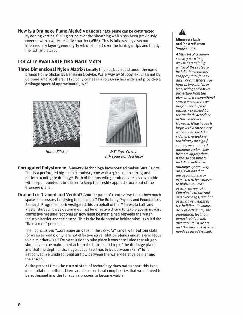
Three Dimensional Nylon Matrix: Locally this has been sold under the name brands Home Slicker by Benjamin Obdyke, Waterway by Stuccofl ex, Enkamat by Colbond among others. It typically comes in a roll 39 inches wide and provides a drainage space of approximately 1/4”.
Home Slicker
MTI Sure Cavity with spun bonded facer
Corrugated Polystyrene: Masonry Technology Incorporated makes Sure Cavity. This is a perforated high impact polystyrene with a 3/16” deep corrugated pattern to mitigate drainage. Both of the preceding products are also available with a spun bonded fabric facer to keep the freshly applied stucco out of the drainage plane.
Drained or Drained and Vented? Another point of controversy is just how much space is necessary for drying to take place? The Building Physics and Foundations Research Programs has investigated this on behalf of the Minnesota Lath and Plaster Bureau. It was determined that for effective drying to take place an upward convective net unidirectional air fl ow must be maintained between the water-resistive barrier and the stucco. This is the basic premise behind what is called the “Rainscreen” principle.
Their conclusion: “...drainage air gaps in the 1/8–1/4” range with bottom slots (or weep screeds) only, are not effective as ventilation planes and it is erroneous to claim otherwise.” For ventilation to take place it was concluded that air gap slots have to be maintained at both the bottom and top of the drainage plane and that the depth of drainage space itself has to be between 1/2–1” for a net convective unidirectional air fl ow between the water-resistive barrier and the stucco.
At the present time, the current state of technology does not support this type of installation method. There are also structural complexities that would need to be addressed in order for such a process to become viable.
Minnesota Lath and Plaster Bureau Suggestions:
A little bit of common sense goes a long way in determining which of these stucco installation methods is appropriate for any given circumstance. For houses two stories or less, with good natural protection from the elements, a conventional stucco installation will perform well, if it is properly executed by the methods described in this handbook. However, if the house is large with a three story walk-out on the lake side, or overlooking the fairway on a golf course, an enhanced drainage system may be more appropriate. It is also possible to install an enhanced drainage system only on elevations that are questionable or expected to be exposed to higher volumes of wind driven rain. Complexity of the roof and overhangs, number of windows, height of the building, fl ashings, deck attachments, site orientation, location, annual rainfall, and architectural style are just the short list of what needs to be addressed.
8

Metal Lath: Based upon local practice, the Minnesota Lath & Plaster Bureau recommends 3.4# self furring galvanized metal lath.
Attachment: The Minnesota Lath and Plaster Bureau proposed this code change which now clearly requires that the fastener penetrate the supports (framing) a minimum of 3/4-inch. This was important because it strengthens the requirement for the proper location and length of the fastener which provides the greatest holding power for the lath. As a second benefi t it also encourages less over fastening into the sheathing in the fi eld between the supports.
Over Fastening. The reason lathers tend to over fasten the lath is to keep it taut and fl at with the sheathing. It is reasoned that in doing this it will be easier for the plasterer to provide a plastered surface that is fl at without waviness. There has been much controversy about the impact of over fastening into the sheathing between wood framing. Anecdotal information now exists that illustrates fasteners coming out the backside of the sheathing can be magnets for frost in the winter months. Condensation occurs when water vapor reaches a saturation (dew) point within the wall. Moisture condenses on thermally conductive surfaces and fasteners poking through the sheathing are more conducive to this phenomenon because they act as thermal bridges from warm indoor air and cold outside air. For this reason then, it is the consensus among many plastering professionals and the Minnesota Lath and Plaster Bureau, that extra fasteners between the framing supports be kept to a minimum and liberal use of fasteners should be avoided. As another option, additional fasteners can be used that do not penetrate the entire thickness of the sheathing in the fi eld of the installation between the supports.
Other Parameters. According to ASTM C 1063 (Standard Specifi cation for Lathing), which is also referenced by the MN Building Code (Section 7.8.2), “Metal Lath shall be lapped 1/2 inch at the sides”...and “1 inch at ends (see photo “A”). Where end laps occur between the framing members, the ends of the sheets of all metal plaster bases (lath) shall be laced or wire tied with 0.0475-in. galvanized, annealed steel wire.” ASTM C 1063, also states (Section 7.10.1.2-3) that “Lath shall be applied with the long dimension at right angles to the supports, unless otherwise specifi ed. Ends of adjoining plaster bases (lath) shall be staggered.”
(continued on following page)
Photo A: Staggering and lapping lath
1 inch min.
1/2 inch min.
2007 MN Building Code Section R703.6.1 Lath.
All lath and lath attachments shall be of corrosion-resistant materials. Expanded metal or woven wire lath shall be attached with 11 gage nails having a 7/16-inch (11.1 mm) head; or 16 gage staples placed no more than 6 inches (152 mm) or as otherwise approved. Nails or staples shall penetrate staples shall penetrate wood framing support wood framing support members not less than 3/4-inch (19 mm).3/4-inch (19 mm).
Lath Inspections Are Required!
See MN Building CodeSection 1300.0210Subparagraph 6, G.
It is incumbent upon the contractor to notify the local building offi cial that his work is ready for inspection. Lath inspections are to be made before any plastering is applied.
9
Metal LathMetal Lath

Corners. ASTM C 1063 (Section 7.11.2) states “Corner beads shall be installed to protect all external corners and to establish grounds.” Section 7.11.2.1 further states that “External corner reinforcement shall be installed to reinforce all external corners where corner bead is not used. Where no external corner reinforcement or corner bead is used, lath shall be furred out and carried around corners at least one support on frame construction.” To provide extra reinforcement and a straighter more uniform corner Stockton Wire Products, Corner Aid (or equivalent) is recommended at these locations.
Corner Aid
10

For ease of installation, weep screeds are generally installed so that the back attach-ment fl ange is fastened through the sheathing and into the mud sill. According to ASTM C1063 (Section 6.3.2) the weep screed “shall have a sloped, solid or perforated ground or screed fl ange to facilitate the removal of moisture from the wall cavity…”
Why are Weep Screeds Important? The easy answer is that weep screeds provide an exit for incidental moisture. Some experts have also speculated that because there is a separation between the ground or pavement, this provides a capillary break. While this may be important, a better, perhaps more important, reason is the fact that it defi nes where the mudsill may be in relation to the ground. This is important because it would be an easy miscalculation to pile backfi ll or landscaping materials against the stucco above the mudsill. This could lead to a moisture intrusion problem that would not ordinarily be suspected.
Are Weep Screeds Always Necessary? No. It should be pointed out that the code requires weep screeds on “exterior stud walls.” In some cases stucco is installed directly on concrete or concrete block. In this case it is not necessary to install a weep screed. However, for aesthetic reasons, some applications on exterior stud walls may require the stucco to continue down over an exposed foundation. In this situation building offi cials have expressly stated that the water-resistive barrier must extend onto the foundation wall to prevent adhesion of the stucco and maintain the drainage plane. The water-resistive barrier must then lap onto the attachment fl ange of the weep screed as previously mentioned.
What is Pavement? This issue can also be confusing because this term implies paths that have been covered with hard surface treatments such as concrete, asphalt or gravel. Some situations arise where a stoop, porch, covered walkway or patio may be called into question. In many cases these elements cannot be classifi ed as pavement because they also have foundations and footings. This is of course open to interpretation by the building offi cial, however, this type of detail is discussed in the “Stucco at Concrete Stoop” detail on the page 13.
(continued on following page)
2007 MN Building Code Section R703.6.2.1 Weep Screeds
A minimum 0.019-inch (No. 26 galvanized sheet gage), corrosion-resistant weep screed or plastic weep screedor plastic weep screed, with a minimum vertical attachment fl ange of 3-1/2 inches (89 mm)(89 mm)shall be provided at or below the foundation plate line on exterior stud walls in accordance with ASTM C 1063-03ASTM C 1063-03. The weep screed shall be placed a minimum of 4 inches (102 mm)(102 mm) above the earth or 2 inches (51 mm)(51 mm) above paved areas and shall be of a type that will allow trapped water to drain to the exterior of the building. The weather-resistant barrier shall lap the attachment fl ange of the weep screed.
Weep Screeds Weep Screeds
11

Weep Screeds Weep Screeds
12
The Double Flanged Weep Screed. Aesthetically, some people want to continue the stucco to below grade. Some experts have expressed concern about this practice often citing capillarity continuity as a reason to avoid this practice. It should be noted, however, that Code Section R406.1, requires 3/8-inch of parging on masonry walls. What is parging other than portland cement plaster? One of the Minnesota Lath and Plaster Bureau members has taken this philosophy one step further by developing and patenting a weep screed profi le which allows the stucco to be installed to below grade. See detail below.
The Double Flanged Weep Screed is subject to approval by your local code offi cial. The Double Flanged Weep Screed is subject to approval by your local code offi cial. The Double Flanged Weep ScreedThis component is locally available through Winroc Inc.
For contact information see Appendix B. For more information on the Double Flanged Weep Screed see www.weepscreed.com.

Stucco at Stoop
This is a detail that was added in 2003 to this handbook in response to a perceived need to address this condition.
What frequently happens in this scenario is that the concrete stoop is poured directly against the framing. This presents an awkward condition where the stoop is above the level of the plate line and the integrity of the drainage plane is lost. This issue is less of a problem in a situation where the stoop is part of a covered porch, however, this should not be a reason for ignoring this condition.
The easiest way to maintain the integrity of the drainage plane is to simply install a piece of adhesive backed membrane fl ashing that bridges the transition from the sheathing to the foundation wall.
To keep moisture out of the juncture between the framed wall and the concrete stoop we have suggested that a corrosion-resistant metal fl ashing be set in a bed of sealant over the concrete pour. The building paper then laps over the fl ashing for positive drainage. In lieu of stopping the stucco with a casing bead as shown, a weep screed could also be used at this location. In that scenario, however, the building paper should lap over the back vertical fl ange of the weep screed instead of behind it as pictured in this detail.
2007 MN Building Code Section R703.8, Subsection 5 (see Appendix A)
Stucco at Concrete StoopStucco at Concrete StoopStucco at Concrete StoopStucco at Concrete Stoop
13
This is a new code section for 2007. The use of control and expansion joints in residential construction is not widely practiced in Minnesota. That is not to say that they are inappropriate for residential construction in all cases. However, the responsibility for their use is up to the discretion of the plaster application designer.
CONTROL JOINTS
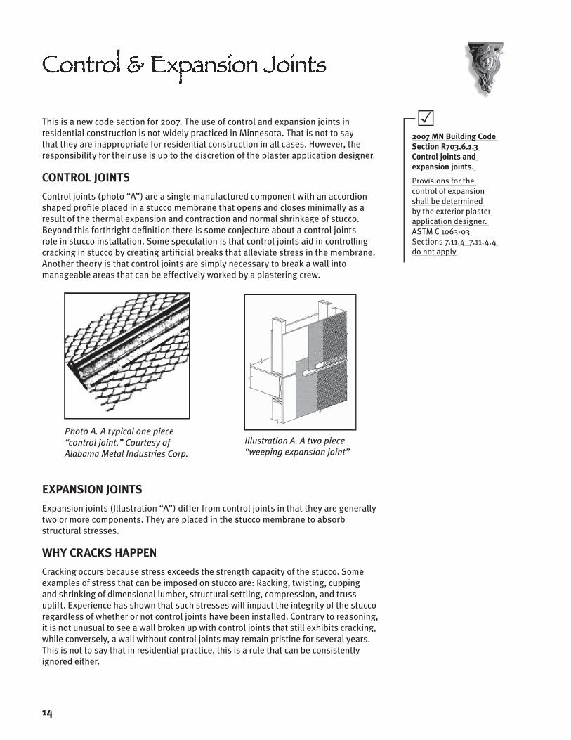
Control joints (photo “A”) are a single manufactured component with an accordion shaped profi le placed in a stucco membrane that opens and closes minimally as a result of the thermal expansion and contraction and normal shrinkage of stucco. Beyond this forthright defi nition there is some conjecture about a control joints role in stucco installation. Some speculation is that control joints aid in controlling cracking in stucco by creating artifi cial breaks that alleviate stress in the membrane. Another theory is that control joints are simply necessary to break a wall into manageable areas that can be effectively worked by a plastering crew.
Photo A. A typical one piece “control joint.” Courtesy of Alabama Metal Industries Corp.
Illustration A. A two piece “weeping expansion joint”
EXPANSION JOINTS
Expansion joints (Illustration “A”) differ from control joints in that they are generally two or more components. They are placed in the stucco membrane to absorb structural stresses.
WHY CRACKS HAPPEN
Cracking occurs because stress exceeds the strength capacity of the stucco. Some examples of stress that can be imposed on stucco are: Racking, twisting, cupping and shrinking of dimensional lumber, structural settling, compression, and truss uplift. Experience has shown that such stresses will impact the integrity of the stucco regardless of whether or not control joints have been installed. Contrary to reasoning, it is not unusual to see a wall broken up with control joints that still exhibits cracking, while conversely, a wall without control joints may remain pristine for several years. This is not to say that in residential practice, this is a rule that can be consistently ignored either.
Control & Expansion JointsControl & Expansion JointsControl & Expansion JointsControl & Expansion Joints
14
2007 MN Building Code 2007 MN Building Code Section R703.6.1.3 Section R703.6.1.3 Control joints and Control joints and expansion joints.expansion joints.
Provisions for the control of expansion control of expansion shall be determined by the exterior plaster by the exterior plaster application designer. application designer. ASTM C 1063-03 ASTM C 1063-03 Sections 7.11.Sections 7.11.44–7.11.4.4 7.11.4.4 do not apply.do not apply.

The main reason for their lack of use in residential applications is the simple fact that wall areas tend to be smaller than commercial installations. Stucco contractors are also reluctant to use them because they are aesthetically objectionable to homeowners. This is a matter of some controversy for commercial stucco installers who feel that there is a double standard that needs to be reformed.
Expansion joints are a good idea in wood framed construction (photo “B”) where there are More than two stories. Expansion joints are generally positioned at fl oor lines where wide dimensional lumber is used for framing. Typically these large pieces of lumber will react in new construction by shrinking perpendicular to the grain direction. Additional stories of height can also result in structural compression and settling. These issues can create stresses that exceed the strength capacity of the stucco with the end consequence being a crack.
Photo B: Multi-story construction broken up with control joints (vertical) and expansion
joints (horizontal) at fl oor lines
Yet another motivation for using an expansion joint in multiple story construction is as an outlet for incidental moisture that may get behind the stucco. In this context the joint can also be confi gured to provide a weep function (see Illustration “A”).
With the growing trend of larger houses, comes the real concern that perhaps control and expansion joints should be introduced into larger wall areas. However, with their introduction into a wall area comes the added concern that these components open up another potential avenue for water entry into the wall assembly. The MN Lath and Plaster Bureau suggests that the use of control joints be discussed with the homeowner or his representative. As in commercial construction their use should be judged by the size and complexity of the wall area(s).
As referenced by the MN Building Code, ASTM C 1063 requires that “control joints be installed in walls to delineate areas not more than 144 ft…The distance between control joints shall not exceed 18 ft in either direction or a length to width ratio of 2 to 1…” At the present time ASTM C 1063 does not differentiate between control and expansion joints. For more information on control and expansion joints please see our companion booklet to this publication The Lath Inspection Resource Manual available online at www.mnlath-plaster.com. Click on the “Building Offi cials” tab to access the link to this document.
15

This information was inspired by the fact that much precast stone veneer is adhered to a portland cement plaster base applied as part of the installation operation.
MORTAR THICKNESS BEHIND VENEER
According to MN Building Code Section R703.6.2 “If the plaster surface is completely covered by veneer or other facing material or is completely concealed, plaster application need be only two coats, provided the total thickness is as set forth in Table R702.1(1).” When measured from the back plane of expanded metal lath that thickness is 3/4 inch. This is at odds with procedures referenced in Figure R703.7 and Section R703.7.4.3 of the International Residential Code (IRC) which notes a 1-inch mortared space behind the veneer. In either event, in order to be code compliant you should anticipate that the combined thickness of the portland cement plaster base and the bedding mortar used to set the veneer be a minimum of 1-inch.
WATER-RESISTIVE BARRIERS
Section R703.7.4.3 states “When the 1-inch space is fi lled with mortar, a weather-resistant membrane or building paper as described in Section R703.2 and R703.6.3 is required over studs or sheathing.” While the issue of two layers of water-resistive barrier (WRB) has been specifi c in the code with respect to stucco installation over wood based sheathing, this is a new requirement relative to precast stone veneer. Considering the obvious correlation between the installation of both products, the requirement for two layers of water-resistive barrier needs to be observed for precast stone veneer as well.
FASTENERS
The weight of a portland cement plaster base and bedding mortar used in installing precast stone veneer is approximately 12 lbs./SF. Combine this with the weight of the precast stone (approx. 11–15 lbs./SF) and you are looking at 23–27 lbs. of weight attached to the wall surface. It is, therefore, critical that the lath and its fasteners to the supports be of the best quality. In this regard the Minnesota Lath and Plaster Bureau suggests 3–4 #/sq. yd., self furring galvanized metal lath. Code Section R703.7.4.4 now requires lath attachment fasteners penetrate wood supports a minimum of one-inch. Consideration should also be given to proper design which includes veneer support elements such as lintels and metal ties. Please consult the precast stone manufacturer and the building code for further information.
TERMINATION AT GRADE
At the time of this printing some precast stone manufacturers require that the fi nished edge of the stone terminate 4” above grade as per code requirements for stucco. Some manufacturer’s actually recommend using stakes pounded into the ground with a horizontal 2” x 4” to prop up the veneer while the bedding mortar dries. Similar to stucco installations the drainage plane must be unencumbered to properly weep moisture that may fi nd its way in back of the precast stone veneer.
16
2007 MN Building Code Section R703 and Figure R703.7

Precast Stone Veneer
A common complaint about stone veneer is that it does not terminate cleanly but appears to simply be fl oating. In most cases aesthetics dictate that the stone dies into the ground, however, this is not practical or advisable, given code requirements. In this respect the illustration above is consistent with the requirements described in fi gure R703.7 of the building code. Another option that may be considered is to step foundation walls as necessary to accommodate fi nished grade requirements. Still another option is to integrate brick seats (ledges) into foundation walls for a more aesthetically pleasing termination. A prudent suggestion is to consult the manufacturer’s requirements before proceeding. As far as weeping this type of construction, Section R703.7.6 of the building code requires that 3/16-inch diameter minimum weeps be placed at a maximum spacing of 33-inches on center immediately above the fl ashing.
ENHANCED DRAINAGE
The Builders Association of Minnesota believes that a drainage plane will help reduce potential water intrusion issues if it is used behind precast stone and masonry veneer. BAM was behind a code amendment that would allow builders and remodelers to use a drainage material behind these claddings without receiving prior approval from code offi cials. See Appendix A for Minnesota State Building Code Section R703.7.4.2 and other related code sections on this cladding.
17

TRANSITION AT BRICK (ILLUSTRATION BELOW LEFT)
Combining stucco with another cladding such as brick adds aesthetic interest. The transition between the two claddings can become awkward because the brick is generally offset from the stucco.
The best way to handle this transition is to provide a fl ashing that is set in place before the plasterer installs the stucco.
Note that the water-resistive barrier laps over the back leg of the fl ashing for positive drainage.
Transition at Brick Veneer (wall section)
Vertical Transition at Vinyl Siding (plan section)
VERTICAL TRANSITION AT VINYL SIDING (ILLUSTRATION ABOVE RIGHT)
Stucco sometimes is used only on the front side of a home and another cladding used on the other three. In this detail vinyl siding is illustrated.
Section R703.2 and Table R703.4 of the Minnesota State Building Code mandates that water-resistive sheathing paper be installed behind all exterior coverings. With this transition in claddings, it is important that the water-resistive barrier used behind the stucco and the vinyl overlaps a minimum of 6” for continuity. It is also important to seal the juncture between the stucco and vinyl with backer rod and low modulus elastomeric sealant. For more information on sealants see “Selecting Sealants” page 31.
Other Common TerminationsOther Common TerminationsOther Common TerminationsOther Common Terminations
18
2007 MN Building Code Section R703.8, Subsection 8 (see Appendix A)

19
COLUMN AT CONCRETE STOOP (ILLUSTRATION BELOW LEFT)
A frequently seen detail on entries is stucco columns on top of concrete stoops.
With this type of construction comes the prospect of water fi nding it’s way behind the interface where the column construction meets the concrete stoop.
One of the better ways to avoid water intrusion issues at these locations is simply to raise the construction above the level of the concrete stoop with a small concrete pad or curb.
The water-resistive barrier is then lapped over the concrete pad for positive drainage and the stucco is terminated with a casing/stop bead. A small gap is suggested between the casing bead and the concrete stoop for thermal movement, to minimize corrosion of the stop bead and as a capillary break from standing water.
Column at Concrete Stoop
Drained Cantilevered Projection
DRAINED CANTILEVERED PROJECTION (ILLUSTRATION ABOVE RIGHT)
This is a new detail that was put together in response to a contractor’s request that this be addressed. If it is not weeped, incidental moisture from the vertical wall plane could become trapped and pent up in the soffi t. This could lead to eventual rot and splitting of the stucco membrane over time.
The likely scenario in a residential installation is where you might fi nd a cantilevered wall plane over a fi rst story walk-out, or where there is a projecting bay window. The simple solution to this problem is to provide a weep at the intersection of the wall and soffi t. To do this, a break has to be created using a horizontally oriented casing bead at the soffi t and another casing bead oriented at 900 on the vertical wall. Between these two elements the water-resistive barrier will allow incidental moisture to pass. In this construction it is also advisable to set the vertically oriented casing bead so that it projects slightly below the soffi t to create a drip stop. This breaks the natural surface tension of water that fl ows down the stucco on the vertical wall plane, and keeps it from back fl owing around the corner to the soffi t.
2007 MN Building Code Section R703.8(see Appendix A)

CHIMNEYS (ILLUSTRATION BELOW LEFT)
Stucco has often been used in the past to weatherproof and decorate concrete block chimneys. Appearance is deceiving in today’s construction however, as the chimney is often composed of a fi re rated metal fl ue with a framed chase enclosed with sheathing. The outward appearance is similar to what we have seen in the past, but the construction of these enclosures is a critical aspect to moisture infi ltration into the assembly.
Chimney Cap: From the top of the chimney a metal cover is installed to cover the chase opening. This is the only defense of the enclosure to the elements. It should be watertight and extend over the top edge of the stucco. Wind driven rain can fi nd it’s way between the interface of the stucco and the cap fl ashing, so it is suggested that this interface be sealed with a good quality elastomeric sealant. Please note: Considering the vulnerability of this construction to the effects of wind driven rain we changed this detail in 2003 to show a 2.5” overlap over the stucco.
Cricket: Sometimes referred to as a saddle, a cricket is installed on the high side of the chimney to divert water away from the construction. Crickets are especially critical on today’s homes where roof lines are steeply pitched. To perform optimally, they must be properly fl ashed and weather tight.
Sealant installed by General Contractor
Roof/Wall Intersection
ROOF/WALL INTERSECTIONS (ILLUSTRATION ABOVE RIGHT)
Roof rakes at stucco walls: Dormers and chimneys that extend up from roofs are not unusual challenges in today’s homes built with multiple roof lines. However, attention must be paid to these locations.
Roofi ng Felt: It is good practice to base fl ash prior to the installation of metal fl ashing. This is accomplished by simply extending the felt or adhesive backed membrane from the roof slightly up the vertical wall (see illustration).
Roof Line IssuesRoof Line Issues
20
Note: The intent of any of these details is to keep water out. There are other options that may be equal or even more effective.
2007 MN Building Code Section R703.8, Subsections 2 and 3 (see Appendix A)
2007 MN Building Code Section R703.8, Subsection 6. (see Appendix A)

21
KICK-OUT FLASHING
Flashing: Step fl ashing is preferred over continuous fl ashing along a roof rake because it is interlaced with the shingles for positive
drainage away from the wall/roof interface.
Kick-out Diverter (ILLUSTRATION BELOW LEFT): A critical location where moisture entry can do considerable damage is where a lower roof overhang stops in the middle of a stucco wall. Kick-outs should be fabricated with watertight seems and be big and broad enough to handle water run-off from a variety of roof pitches. Another critical element is the use of gutters to evacuate the water away from these sensitive locations. There are several local materials suppliers that offer these kick-outs in both a left and right hand version (contact one of the suppli-ers listed on Appendix B, for further information). Installing the kick-out after the installation of the shingles is a very diffi cult procedure for the lather or stucco contractor to perform. For this reason it should be coordinated so that the kick-out is installed by the roofer as the shingles are being laid up.
Installed by Roofer
Note: Dimensions may need to be adjusted Note: Dimensions may need to be adjusted depending on site conditions
Installing Water-Resistive Barrier
Installing Water-Resistive Barrier: Proper building paper installation should be left to the stucco contractor. Building paper should be installed to lap over the back fl ange of the kick-out and the step fl ashings for positive drainage. Care should be taken to cut the paper tightly around the kick fl ange. The subsequent cut should be mended with adhesive backed membrane material, to lap onto the kick fl ange for a water tight seal (see illustration above right).
Stucco Termination: Over the years the preferred method of terminating the stucco above a roof was to simply die it into the shingles. Another option has been to provide a stop bead above the shingles. Either method has its advantages and draw backs.
Dying the Stucco into the Shingles: While this option is aesthetically a more pleasing termination it should be considered with an eye towards the future. Be-cause when the shingles must be replaced, they will have to be cut out very care-fully along the edge of the stucco. Some experts also caution against this approach because there is no capillary break between the stucco and the shingles.
(continued on following page)
2007 MN Building Code Section R703.8
Subsection 9: Approved corrosion-resistant fl ashing shall be installed “Where the lower portion “Where the lower portion of a sloped roof stops of a sloped roof stops within the plane of an within the plane of an intersecting wall cladding intersecting wall cladding in such a manner as to divert or kick out water away from the assembly.”away from the assembly.”(see also Appendix A)
Stopping the Stucco with a Casing Bead
Stopping the Stucco with a Casing Bead: This termination will make it easy to remove and replace shingles at a later time, but it is often aesthetically objectionable because it exposes the fl ashing above the roof line. Caution must also be taken in positioning the attachment fl ange on the wall, so that no fasteners puncture the wall fl ashing (see illustration left).
Stopping the Stucco with a Weep Screed: This method of termination has been the matter of some discussion. Although it is feasible, it presents some complications in making the kick-out fl ashing watertight with adhesive backed membranes. For this reason we would caution against using such a method. As illustrated, the fact that the building paper laps under the attachment fl ange of the casing bead should be suffi cient for the passage of incidental moisture from behind the stucco.
EAVES/SOFFITS
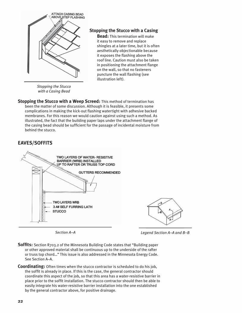
Section A–A
Legend Section A–A and B–B
Soffi ts: Section R703.2 of the Minnesota Building Code states that “Building paper or other approved material shall be continuous up to the underside of the rafter or truss top chord…” This issue is also addressed in the Minnesota Energy Code. See Section A–A.
Coordinating: Often times when the stucco contractor is scheduled to do his job, the soffi t is already in place. If this is the case, the general contractor should coordinate this aspect of the job, so that this area has a water-resistive barrier in place prior to the soffi t installation. The stucco contractor should then be able to easily integrate his water-resistive barrier installation into the one established by the general contractor above, for positive drainage.
22

Legend Section A–A and B–B
GABLE ENDS
The intention of making the water-resistive barrier continuous up to the underside of the rafter in the previous detail is to prevent the accumulation of moisture from wind driven rain. While most contractors have begun to accept this detail, the same level of attention does not seem to always occur at the gable ends, where the stucco meets the soffi t. For this reason we have included the detail (Section B–B).
Section B–B
Similar to the objective described above the intent of this detail is to limit its exposure to wind driven rain. Note the blocking used as a nailer is the same thickness as the stucco. The fascia is then cut wider to provide an acceptable overlap of the stucco. The fascia trim is then sealed along the solid soffi t for another level of protection at this area.
As an added level of redundancy, the building paper could also be sealed at the soffi t or adhesive backed membrane could be used.
23

MNLPB Position. MNLPB Position. With respect to windows and doors, it is incumbent upon the general contractor to ensure that the rough openings are properly fl ashed before the window or door unit is installed. Failure to perform this task can result in moisture intrusion, mold, rot and ultimately structural damage.Code Section R703.8 specifi cally addresses windows in subsection 1: “Approved corrosion-resistant fl ashing shall be installed” at “Exterior window and door openings. Flashing at exterior window and door openings shall extend to the exterior wall fi nish or to the water-resistive
barrier for subsequent drainagebarrier for subsequent drainage.” The underlined portion of this section is new in the International Residential Code from previous versions. The Minnesota Lath and Plaster Bureau and others objected to this new language. To put our position in perspective we would ask this question: Is it appropriate to fl ash a piping vent through a roof to the asphalt felt paper underlayment below the shingles? Of course not, fl ashing is supposed to be installed to daylight and hence the fl ashing for a piping vent always exits out over the shingles. How is fl ashing a window any different? Nailing fl ange windows prevent good fl ashing technique and we are led to believe that water-resistive barriers provide an acceptable alternative to corrosion-resistant fl ashing.
In this context the Minnesota Lath & Plaster Bureau suggests that the best option for fl ashing a window is a “true” pan fl ashing. A true pan fl ashing is generally fabricated from brake formed corrosion resistant sheet metal or PVC plastic. It is placed on the sill of the rough opening prior to the insertion of the window (see illustration). Moisture that penetrates through the window construction is then safely exited over the exterior surface of the stucco. This process for installing pan fl ashing should not be confused with what has been proposed in the new Code Section R703.8.1 ( box) which is essentially described in the step by box) which is essentially described in the step by boxstep processes described on the following pages.
A “true” pan fl ashing is common practice on commercial projects but also would be effective in residential applications, especially if the window is suspect or has no slope for positive drainage at the sill. The limitation to the practice, however, is the bottom nailing fi n, which must be removed to accept the pan fl ashing. Removal of the bottom fi n may result in the window manufacturer voiding any warranty that may come with the window. Other consideration must be given to sizing the rough opening accordingly to accommodate the extra build-up of materials. As an option a true pan fl ashing can be installed prior to step 4 in the procedure that follows. Short of installing a true pan fl ashing under the window the next best alternative is the procedure illustrated in the following pages. Before proceeding, please consult the window manufacturer for specifi c installation requirements.
24
2007 MN Building Code Section R703.8 Flashing.(see Appendix A)
Approved corrosion-resistant fl ashing shall be applied shingle fashion in such a manner as to prevent entry of water into the wall cavity or penetration of water to the building structural framing components. The fl ashing shall extend to the surface of the exterior wall fi nish
2007 MN Building Code Section R703.8.1 Pan fl ashing of windows and doors.
A pan fl ashing shall be provided A pan fl ashing shall be provided under all exterior windows and doors. Pan fl ashing shall be doors. Pan fl ashing shall be (a) sloped to drain water to the (a) sloped to drain water to the exterior surface of a weather-resistive barrier or fl at with sealed back dam and side dams to prevent re-entry of water to prevent re-entry of water into the wall cavity or onto into the wall cavity or onto interior fi nishes and (b) maintain interior fi nishes and (b) maintain the thermal envelope of the the thermal envelope of the building. Pan fl ashing made from building. Pan fl ashing made from metal must be thermally isolated metal must be thermally isolated from interior surfaces.
Exceptions:Exceptions:1. Windows or doors installed
in accordance with the manufacturer’s written instructions which include an alternate fl ashing method.alternate fl ashing method.
2. Windows or doors in detached accessory structures.accessory structures.
3.3. Skylights, bow or bay Skylights, bow or bay windows.
4.4. Doors required to meet Doors required to meet accessibility requirements accessibility requirements that would prevent the that would prevent the installation of pan fl ashing.installation of pan fl ashing.
5.5. Repairs or replacement of Repairs or replacement of existing windows.existing windows.
6. When a method is provided When a method is provided by a registered design by a registered design professional.professional.
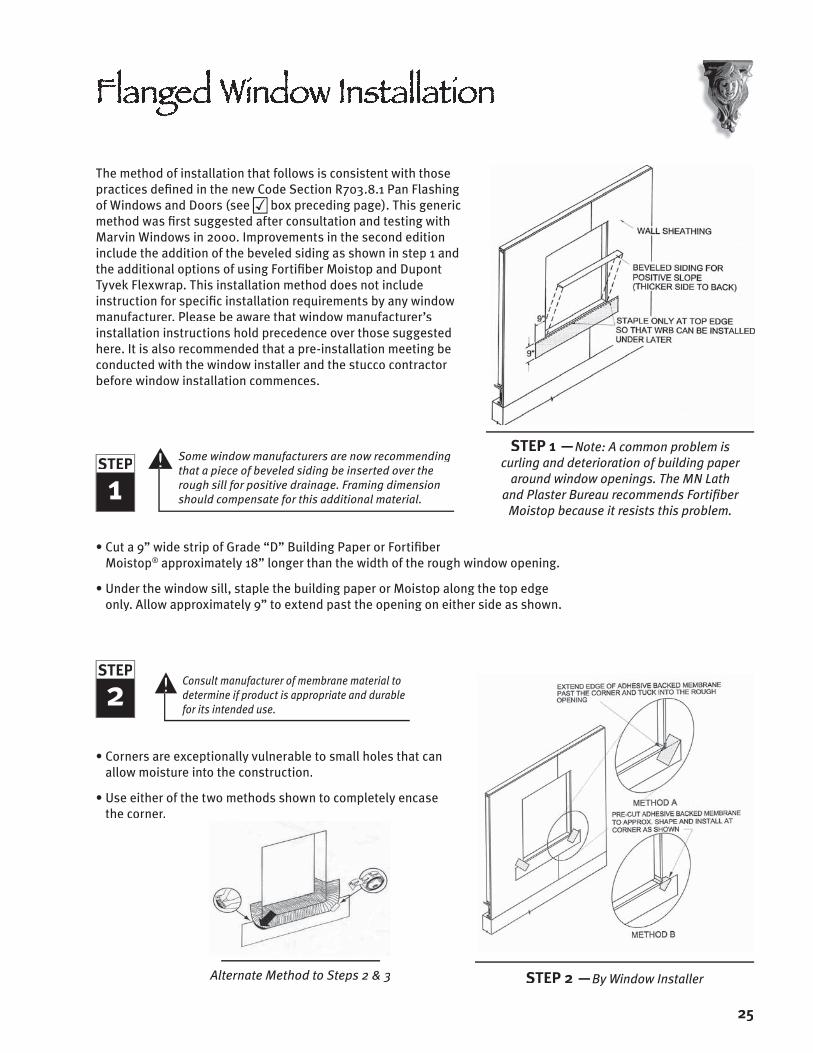
The method of installation that follows is consistent with those practices defi ned in the new Code Section R703.8.1 Pan Flashing of Windows and Doors (see box preceding page). This generic box preceding page). This generic boxmethod was fi rst suggested after consultation and testing with Marvin Windows in 2000. Improvements in the second edition include the addition of the beveled siding as shown in step 1 and the additional options of using Fortifi ber Moistop and Dupont Tyvek Flexwrap. This installation method does not include instruction for specifi c installation requirements by any window manufacturer. Please be aware that window manufacturer’s installation instructions hold precedence over those suggested here. It is also recommended that a pre-installation meeting be conducted with the window installer and the stucco contractor before window installation commences.
1STEP
Some window manufacturers are now recommending that a piece of beveled siding be inserted over the rough sill for positive drainage. Framing dimension should compensate for this additional material.
• Cut a 9” wide strip of Grade “D” Building Paper or Fortifi ber Moistop® approximately 18” longer than the width of the rough window opening.
• Under the window sill, staple the building paper or Moistop along the top edge only. Allow approximately 9” to extend past the opening on either side as shown.
2STEP
Consult manufacturer of membrane material to determine if product is appropriate and durable for its intended use.
• Corners are exceptionally vulnerable to small holes that can allow moisture into the construction.
• Use either of the two methods shown to completely encase the corner.
Alternate Method to Steps 2 & 3
Flanged Window InstallationFlanged Window InstallationFlanged Window InstallationFlanged Window Installation
25
STEP 2 —By Window Installer
STEP 1 —Note: A common problem is curling and deterioration of building paper
around window openings. The MN Lath and Plaster Bureau recommends Fortifi ber
Moistop because it resists this problem.

3STEP • For 2” x 6” construction cut a piece
of 8” adhesive backed membrane 8” longer than the window opening (top illustration).
• Make a 2” cut in the membrane, 4” in from the ends as shown.
• Peel backing off of membrane and install as shown. Note that 4” of the membrane rides up onto the rough jamb and folds out and over the face of the sheathing. The remaining 2” at the sill folds down and sticks over the previously installed building paper or Moistop.
• As another method for steps 2 and 3, Dupont Tyvek FlexWrap™ or equivalent material can be installed (see illustration below). Be sure to secure the corners with staples or Tyvek Tape as shown.
Alternate Method to Steps 2 & 3
4STEP
If metal or PVC pan fl ashing is to be used, install now
• Cut Grade D Building Paper or Fortifi ber Moistop®
approximately 15” wide x 24” longer than the height of the window opening.
• Cut out corners of building paper or Moistop as shown.
• Fold and install building paper or Moistop to cover the rough jamb and fold out onto the face of the sheathing. Staple into place, except for the bottom 12”.
26
STEP 4 —By Window Installer
STEP 3 —By Window Installer

27
5STEP • Install beveled wedges or siding at sill,
oriented opposite to the siding previously installed in step 1. Do not nail into place.
• Per window manufacturers instructions, apply a continuous bead of compatible sealant at the top and sides of the window opening or along the back of the nailing fi n immediately before the installation of the window.
• Install the window following window manufacturers fastening requirements.
NOTE: Do not apply sealant to back of bottom nailing fi n. This is to allow for positive drainage.
6STEP • If the joinery of the nailing fi ns on the
window are not self sealing, install sealant at the fl ange/window frame interface, as required by the window manufacturer.
• If the window does not come with an integral drip cap head fl ashing, one should be purchased from the manufacturer, or vendor as recommended by the manufacturer.
• Carefully follow window manufacturers instructions for installation of the drip cap fl ashing.
• Note: Some manufacturers require a continuous bead of sealant under both the vertical and horizontal legs of the drip cap fl ashing before installallation.
STEP 5 —By Window Installer
STEP 6 —By Window Installer

28
7STEP
• If nailing fi ns do not have a continuous seal around the corners, install gaskets that come with the windows
• Carefully follow window manufacturer’s instructions for the installation of any gasket materials or necessary sealants that must be applied for proper installation of the window unit.
8STEP • On wood sheathed construction the 2007
Minnesota State Building Code (Section R703.6.3) allows two layers of Grade D building paper. It is acceptable to apply the building paper in a double ply roll.
• According to code, the water-resistive barrier must be installed shingle style so that each subsequent horizontal course overlaps the previous a minimum of 2”. Vertical joints should be lapped 6”.
• Note that the two layers of water-resistive barrier (WRB) below the sill are tucked under the building paper or Fortifi ber Moistop installed before the window.
• At the jambs, install the double layer of WRB so that it laps over the nailing fi n and abuts the window jamb.
• Continue installing courses beyond the height of the window unit as shown.
STEP 7 —By Window Installer
STEP 8 —By Stucco Contractor

9STEP • Install vertical strips of adhesive • Install vertical strips of adhesive • Install vertical strips of adhesive • Install vertical strips of adhesive
membrane over the WRB and nailing fi ns to fold up and onto the window jamb (see blow-up right). Cut membrane and fold back as shown. Membrane should extend past the nailing fi ns at the head and sill.
• Install another layer of membrane fl ashing horizontally over the back fl ange of the drip cap. Membrane fl ashing at the head should extend and cover the membrane previously installed at the jambs.
• If the drip cap is integral to the window unit, apply the membrane fl ashing over the head similar to what has been described above.
10STEP
• Size and cut the double layer of WRB to • Size and cut the double layer of WRB to • Size and cut the double layer of WRB to • Size and cut the double layer of WRB to bridge over the opening between the WRB at the sides of the jambs.
• Note that the WRB extends past the WRB previously installed at the jambs by 6”. This is to provide positive drainage and conform to MN Building Code requirements (Section R703.2).
NOTE: The intent of any of these details is to keep water out. There are other options that may be equal or even more effective.
29
STEP 9 —By Stucco Contractor
STEP 10 —By Stucco Contractor

WINDOW IMPLICATIONS
• Window frames expand and contract due to temperature changes. Some, much more than others. This may result in signifi cant cracking at the juncture between the window and the stucco leading to a water intrusion issue.
• To compensate for this expansion and contraction, a space between the cladding and the window frame is created by stopping the stucco approximately 3/8” away from the window frame with a component called a casing bead or stop bead (see illustration).
Sealant by General Contractor
• Care should be taken to avoid fastening the stop bead into the window nailing fi n. Fastening into the nailing fi n will cause cracking in the stucco.
• The subsequent joint between the window and stucco at the sill and the jambs are then fi lled with a closed cell bond breaker and low modulus elastomeric sealant (see bottom illustration).
• At the window head, the joint between the drip cap fl ashing and casing bead is not sealed with backer rod and sealant, but left open to weep incidental moisture.
• Care should be taken to ensure that the interface of the casing beads and the drip cap fl ashing at the jamb is properly sealed against moisture intrusion.
(continued on following page)
Stopping Stucco Around WindowsStopping Stucco Around WindowsStopping Stucco Around WindowsStopping Stucco Around Windows
30
2007 MN Building Code Section R703.6, ASTM C 1063, 7.11.3
The issue of stopping stucco around penetrations is addressed indirectly by reference to ASTM Standard Specifi cation C 1063. Section 7.11.3 of this document states that “Nonload-bearing members shall be isolated from load-bearing members, and all penetrating elements, with casing beads or other suitable means, to avoid transfer of structural loads, and to separate from dissimilar materials.”

SELECTING SEALANTS
When selecting sealants consideration should be given to the products movement capabilities, durability and compatibility with other materials. For these reasons the manufacturer of these products should be consulted.
Sealant is not a maintenance free material. Depending on the type, sealants may have to be checked regularly to ensure optimum performance. Generally, sealant manufacturers provide detailed written instruction for the proper installation of their materials. This often is quite involved in the description of mixing, use of bond breaker materials, primers, shape, thickness and size of the sealant bead. Failure to follow these instructions often will void any intended warranty.
Stopping Stucco Around Windows Stopping Stucco Around Windows Stopping Stucco Around Windows Stopping Stucco Around Windows
31
There are several types of sealants currently available: Polyurethanes are perhaps the most adaptable product with respect to color matching, but they are not as elastic as others and sometimes require mixing multiple components on site. Silicones provide the best elasticity properties and are longer lasting but have a limited color palette. A more recent innovation in sealant technology is silyl-terminated sealants. For more information on sealants contact the manufacturers listed on Appendix C.

1STEP
2007 MN Building Code Section R703.8, Subsection 5 (see Appendix A)
This detail was revised in 2003 from the fi rst version due to comments from a variety of people. The major change is the addition of fl ashing at the top of the rim joist as well as under it as originally suggested.
• Position and attach two layers of water-resistive barrier at location where deck header will be attached.
• Position and attach corrosion resistant metal fl ashing so that horizontal leg aligns with fi nal position of the bottom of the deck rim joist.
• Fabricate corrosion resistant metal end dam. Position and attach at the end of the fl ashing.
2STEP
• Fabricate a corner patch from adhesive backed membrane and install at internal corner of end dam.
• Seal small hole in corner of end dam with elastomeric sealant for weather tight seal.
• Install adhesive backed self healing membrane over the metal fl ashing. Height of membrane should be the width of the rim joist plus 4 inches.
3STEP • Deck rim joist can be installed now. Provide
corrosion resistant washers or pipe sleeve spacer (no more than 1/2” long) between deck rim joist and wall construction for positive drainage and drying behind the deck. Be sure to seal the penetration of the fastener into the wall assembly.
• It is suggested that small saw kerfs (1/8” deep max. and perpendicular to its length) be put into the bottom of the rim joist to optimize positive drainage.
(continued on following page)
STEP 2 —By General Contractor
STEP 3 —Flashing by General Contractor, Building Paper by Stucco Contractor
STEP 1 —By General Contractor
323232

4STEP • Install corrosion resistant metal fl ashing
with end cap over the rim joist (by General Contractor). Allow capped end of fl ashing to extend beyond the end of the joist approximately 1/2 inch.
• For added protection a bead of elastomeric sealant can be installed on the top edge of the rim joist prior to installing the fl ashing.
• For positive drainage, install two layers of water-resistive barrier to lap over the fl ashing and other building papers already installed.
5STEP
• Install stop bead around perimeter of opening prior to installation of lath and stucco (by Stucco Contractor).
• Space and install stop bead approximately 3/8 inch away from end dam fl ashing. Note that this will provide a space for a weather tight seal using bond breaker and elastomeric sealant (by Stucco Contractor).
• Install closed cell backer and elastomeric sealant after stucco has been fi nished (by General Contractor).
STEP 4 —Flashing by General Contractor,Building Paper by Stucco Contractor
STEP 5 —Stop bead by Stucco Contractor,Sealant by General Contractor
33

• Handrail newel posts should be attached through the previously installed stucco, into solid supporting framing.
• It is suggested that corrosion resistant washers be used between the post and the stucco to provide an air space. This will facilitate drying when the construction is wetted by driving rain.
• Be sure to bed the washer against the stucco into a bead of sealant to prevent water entry at these locations.
By General Contractor
PIPING AND VENT SLEEVES (ILLUSTRATION ABOVE RIGHT)
Pipe penetrations that are not well planned are areas of concern for moisture penetration, insects and even mice.
• Before stucco is installed, holes in the water-resistive barrier around pipe penetrations and other openings can be secured by the installation of a manufactured boot sleeve or the method shown in fi gure A. Self sticking membrane fl ashing can be cut to closely frame around the pipe. Sealant can then be applied around the pipe for a secure opening prior to the stucco.
• In the event that the pipe is installed after the stucco, a similar approach can be taken (fi gure B) to make an escutcheon out of sheet metal or PVC that is bedded in sealant and attached to the stucco with masonry screws.
NOTE: There has been some concern about copper tubing penetrations through stucco. According to the Copper Development Association “When copper tube passes through an exterior wall of concrete or masonry, it should be protected by wrapping with an approved tape, installing through a plastic or steel sleeve, and then caulked on each side of the wall for a watertight seal.” Although stucco is not considered either concrete or masonry, this is perhaps advice that should not go unheeded.
DECK HANDRAIL ATTACHMENT (ILLUSTRATION BELOW LEFT)
NEWS BULLETIN
A whole new line of products now exists for these types of conditions. QUICKFLASH offers fl ashing panel boots that work for gas, HVAC, electrical and a host of other applications. See www.quickfl ashproducts.com for more information. QUICKFLASH is sold through Ferguson plumbing supply outlets locally.
34

HOSE BIBS AND DRYER VENTS (ILLUSTRATION BELOW LEFT)
Hose bibs, dryer vents and other fi xture attachments come with covers that naturally nest against the cladding. They are also likely places for moisture to fi nd its way into the wall assembly.
• Many of these fi xtures come with their own gasket material that should be installed between the cover and the stucco.
• If the fi xture does not come with gasket, be sure to bed all covers, fl anges and escutcheons in sealant before fastening them to the wall.
By Stucco Contractor
By General Contractor
LIGHT FIXTURES AND OUTLETS (ILLUSTRATION ABOVE RIGHT)
• Often, very little consideration is given to how electrical service boxes interface with the fi nish cladding. In stucco applications plaster rings (a.k.a. mud rings) should be affi xed over the service box, to bring the face of the box out fl ush with the fi nished stucco surface. This is the responsibility of the Electrician under the General Contractor.
• It is suggested that a bead of sealant be applied around the perimeter of the plaster ring prior to the installation of the water-resistive barrier. This is the stucco contractor’s responsibility.
• Water-resistive barrier should be installed snugly around the plaster ring fl ange.
• The fi xture should be sealed from the weather against the stucco with gasket material that may come with the fi xture or sealant. This is the General Contractor’s responsibility.
DOWNSPOUTSAny opening in a wall cladding may provide a conduit for moisture intrusion. Even something as innocuous as screw used in a downspout attachment should not be overlooked.
• This detail is provided primarily to emphasize the fact that the hole drilled through the stucco should be carefully sealed at the time that the attachment of the downspout is affi xed to the wall.
• Please also note that the Minnesota Lath and Plaster Bureau suggests that the downspout not be fl ush mounted, but rather positioned away from the stucco. This will permit cleaning, and other maintenance to proceed without disturbing the downspout.
By General Contractor
35
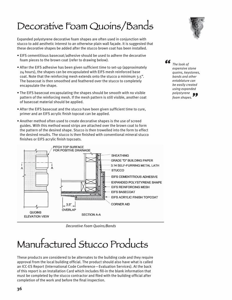
Expanded polystyrene decorative foam shapes are often used in conjunction with stucco to add aesthetic interest to an otherwise plain wall façade. It is suggested that these decorative shapes be added after the stucco brown coat has been installed.
• EIFS cementitious basecoat/adhesive should be used to adhere the decorative foam pieces to the brown coat (refer to drawing below).
• After the EIFS adhesive has been given suffi cient time to set-up (approximately 24 hours), the shapes can be encapsulated with EIFS mesh reinforced base coat. Note that the reinforcing mesh extends onto the stucco a minimum 3.5”. The basecoat is then smoothed and feathered over the stucco to completely encapsulate the shape.
• The EIFS basecoat encapsulating the shapes should be smooth with no visible pattern of the reinforcing mesh. If the mesh pattern is still visible, another coat of basecoat material should be applied.
• After the EIFS basecoat and the stucco have been given suffi cient time to cure, primer and an EIFS acrylic fi nish topcoat can be applied.
• Another method often used to create decorative shapes is the use of screed guides. With this method wood strips are attached over the brown coat to form the pattern of the desired shape. Stucco is then trowelled into the form to effect the desired results. The stucco is then fi nished with conventional mineral stucco fi nishes or EIFS acrylic fi nish topcoats.
Decorative Foam Quoins/Bands
Decorative Foam Quoins/BandsDecorative Foam Quoins/BandsDecorative Foam Quoins/BandsDecorative Foam Quoins/Bands
“ The look of expensive stone quoins, keystones, bands and other entablature can be easily created using expanded polystyrene foam shapes.”
These products are considered to be alternates to the building code and they require approval from the local building offi cial. The product should also have what is called an ICC-ES Report (International Code Conference—Evaluation Services). At the back of this report is an Installation Card which includes fi ll-in the blank information that must be completed by the stucco contractor and fi led with the building offi cial after completion of the work and before the fi nal inspection.
Manufactured Stucco ProductsManufactured Stucco ProductsManufactured Stucco ProductsManufactured Stucco Products
36

APPENDIXAPPENDIX


The following code section is referenced in part on pages 13, 18, 19, 20, 21, 24, 32.
R703.8 Flashing. Approved corrosion-resistant fl ashing shall be applied shingle-fashion in such a manner as to prevent entry of water into the wall cavity or penetration of water to the building structural framing components. The fl ashing shall extend to the surface of the exterior wall fi nish . Approved corrosion-resistant fl ashing shall be installed at all of the following locations:
1. exterior window and door openings. Flashing at exterior window and door openings shall extend to the surface of the exterior wall fi nish or to the water-resistive barrier for subsequent drainage.
2. At the intersection of chimneys or other masonry construction with frame or stucco walls, with projecting lips on both sides under stucco copings.
3. Under and at the ends of masonry, wood, or metal copings and sills.
4. Continuously above all projecting wood trim.
5. Where exterior porches, decks, or stairs attach to a wall or fl oor assembly of wood-frame construction.
6. At wall and roof intersections.
7. At built-in gutters.
8. Where exterior material meets in other than a vertical line.
9. Where the lower portion of a sloped roof stops within the plane of an intersecting wall cladding in such a manner as to divert or kick out water away from the assembly.
Editorial note: A similar reference is made in the roof assemblies section, see below.
903.2.2 Kick-out fl ashing/diverter. A kick-out fl ashing shall be installed where the lower portion of a sloped roof stops within the plane of an intersecting wall cladding, in such a manner as to divert or kick-out water away from the assembly.
The following code sections are referenced on page 16 Precast Stone Veneer.
R703.2 Weather-resistive sheathing paper. A minimum of one layer of No. 15 asphalt felt complying with ASTM D 226 for Type 1 felt or other approved weather-resistive material shall be applied over the sheathing of all exterior walls. See Table R703.4. Such felt or material shall be applied horizontally, with the upper layer lapped over the lower layer not less than 2 inches. Where joints occur, felt shall be lapped not less than 6 inches. Building paper or other approved material shall be continuous up to the underside of the rafter or truss top chord and terminated at penetrations and building appendages in such a manner to meet the requirements of the exterior wall envelope as described in Section R703.1.
Exception: Such felt or material is permitted to be omitted in the following situations:
1. In detached accessory buildings.
2. Where specifi cally prohibited by a sheathing and/or siding manufacturer.
R703.7.4.2 Air space. The veneer shall be separated from the sheathing by an air space of a minimum of a nominal 1 inch (25 mm) but not more than 4 1/2 inches (114 mm).
Exception: The air space can be less than the nominal 1 inch when one layer of weather-resistive barrier complying with R703.2 is installed and a drainage space that allows bulk water to fl ow freely behind the cladding is installed.
R703.7.4.4 masonry veneer on sheathed substrates. On sheathed substrates, a corrosion-resistant, self-furring expanded metal lath shall be installed over the weather-resistant membrane or building paper with appropriate fasteners as described in Section R 703.6.1. Fasteners shall penetrate wood supports a minimum of one-inch.
Additional Changes to the Additional Changes to the Additional Changes to the Additional Changes to the Additional Changes to the Minnesota State Building CodeMinnesota State Building CodeMinnesota State Building CodeAdditional Changes to the Minnesota State Building CodeAdditional Changes to the Additional Changes to the Minnesota State Building CodeAdditional Changes to the Additional Changes to the Minnesota State Building CodeAdditional Changes to the Minnesota State Building CodeMinnesota State Building CodeAdditional Changes to the Minnesota State Building CodeAdditional Changes to the
APPENDIX A

SIMPLEXConstruction Supplies, Inc.9020 W 35W Service Dr.Blaine, MN 55449Tel: (763) 398-0040Fax: (763) 398-0039E-mail: [email protected]
TAMARACK MATERIALS9300 James Ave. SBloomington, MN 55431Tel: (952) 888-5556Fax: (952) 888-4030Website: www.tamarackmaterials.com
THE LUTZ COMPANY8801 Xylon Avenue NorthBrooklyn Park, MN 55445Tel: (763) 315-5886Fax: (763) 315-5891
SNOW-LARSON, INC.2812 Anthony Lane SSt. Anthony, MN 55418Tel: (612) 789-3543Fax: (612) 789-3550Website: www.snowlarson.com
WINROC380 West 86th St.Bloomington, MN 55420Tel: (952) 698-3500Fax: (952) 698-3456Website: www.winroc.com
J. B. O’MEARA COMPANY12301 Dupont Avenue SouthBurnsville, MN 55337Tel: (952) 890-8604Toll Free: 1 (800) 352-2832 Website: www.jbomeara.com
BROCK WHITE COMPANY2575 Kasota Ave.Tel: (651) 647-0950Fax: (651) 647-0403Website: www.brockwhite.com
KENROC10720 Mankato St. NEBlaine, MN 55449Tel: (763) 450-3644Website: www.kenroc.com/blaine.html
ROSE-FLEISCHAKER ASSOCIATES, INC.333 Washington Ave. N, Suite 302Minneapolis, MN 55401Tel: (612) 349-9885Fax: (612) 349-9886E-mail: patrfa@offi centers.com
Local Material SuppliersLocal Material SuppliersLocal Material SuppliersLocal Material Suppliers
APPENDIX B
SHEATHING ASSOCIATIONS/MANUFACTURERSSHEATHING ASSOCIATIONS/MANUFACTURERS
INTERNATIONAL BILDRITE (218) 283-3900Website: www.bildrite.net
ENGINEERED WOOD ASSOCIATION (PLYWOOD, OSB)(253) 565-6600Website: www.apawood.org
STRUCTURAL BOARD ASSOCIATION (OSB)(905) 475-1100Website: www.osbguide.com
GEORGIA-PACIFIC 1 (800) 284-5347Website: www.gp.com/build
SEALANT MANUFACTURERS
BASF BUILDING SYSTEMS (SEALANT)1 (800) 433-9517Website: www.degussa.com
DOW CORNING (SEALANTS)1 (800) 441-4369Website: www.dowcorning.com
PECORA (SEALANT)PECORA (SEALANT)PECORA1 (800) 523-6688Website: www.pecora.com
TREMCO (SEALANTS)1 (800) 321-7906Website: www.tremcosealants.com
Other Useful ContactsOther Useful ContactsOther Useful ContactsOther Useful Contacts
APPENDIX C

Anderman Plaster & Stucco
Berg Plastering
Brian Peterson Stucco
Brisson Stucco
Buetow Bros. Stucco
Commercial Drywall
A.E. Conrad Company
Custom Drywall, Inc.
Stephen Donnelly Co.
Donn’s Plastering Co.
Foley Stucco Co.
Gausman Plaster & Stucco
Imperial Plastering, Inc.
Imperial Wall Inc.
Integrity Drywall
Kelly Stucco Systems
Kunz Stucco, Inc.
Lusian Stucco Co.
Minuti-Ogle Co., Inc.
Mulcahy, Inc.
Olympic Wall Systems
Petersen-Parenteau Stucco
R.G. Roach Specialties
Signature Stucco
Structural Applicators Inc.
Stucco 1
T & T Stucco
Torrini Plastering Co.
Greg Zimmerman Construction
The Minnesota Lath and Plaster Bureauis proud to represent the following highly qualifi ed and
trained lathing and plastering contractors…
Appendix D

Project Name: ______________________________________
__________________________________________________ (Street Address)
__________________________________________________ (City) (State) (Zip)
Stucco Contractor: __________________________________
__________________________________________________
Date: _____________ Signed ________________________
Please indicate YES, NO or N/A (not applicable) answers. Explain “NO” answers on a separate sheet or under notes.
PRE-START YES NO N/A
Was a pre-installation construction conference held?
Did any details have to be discussed with other trades before proceeding? Describe on separate sheet.
Were there any issues not covered in this checklist? Attach sketches or list as applicable.
SUBSTRATE
Sheathing Type: ___________________________________
Plywood/OSB/Bildrite has 1/8-inch gap between panels?
Sheathing is correctly fastened?
WATER-RESISTIVE BARRIER (WRB) INSTALLATIONWATER-RESISTIVE BARRIER (WRB) INSTALLATION
WRB Type(s): ______________________________________
Two layers of WRB were used over wood based sheathing (MN Code R703.6.3)
WRB wraps internal & external corners?
WRB is lapped shingle style for positive drainage?
Vertical joints lapped a minimum 6-inches? (MN Code R703.2)
Horizontal joints lapped a minimum of 2-inches? (MN Code R703.2)
Breaches created by penetrations sealed? (MN Code R703.2)
WRB is continuous to underside of rafter or truss top chord? (MN Code R703.2)
STUCCO
Acrylic admixture added to scratch and brown mix?
Stucco applied when the ambient temperature was higher than 40º F? ( MN Code R703.6)
Stucco protected from freezing for not less than 24 hours after set occurred? (MN Code R703.6)
Total thickness of scratch and brown coats 3/4-inch? (MN Code R702.1(3)
Brown coat allowed to cure a minimum of 7 days prior to installation of fi nish? (MN Code R702.1(3)
Acrylic fi nish used?
Manufacturer brand & type:
__________________________________________________
Manufactured one-coat stucco was used in this installation?
One–coat stucco manufacturer’s installation card was fi led with building offi cial? (ICC-ES)
NOTES
__________________________________________________
__________________________________________________
__________________________________________________
__________________________________________________
__________________________________________________
__________________________________________________
__________________________________________________
__________________________________________________
__________________________________________________
__________________________________________________
__________________________________________________
__________________________________________________
__________________________________________________
APPENDIX E
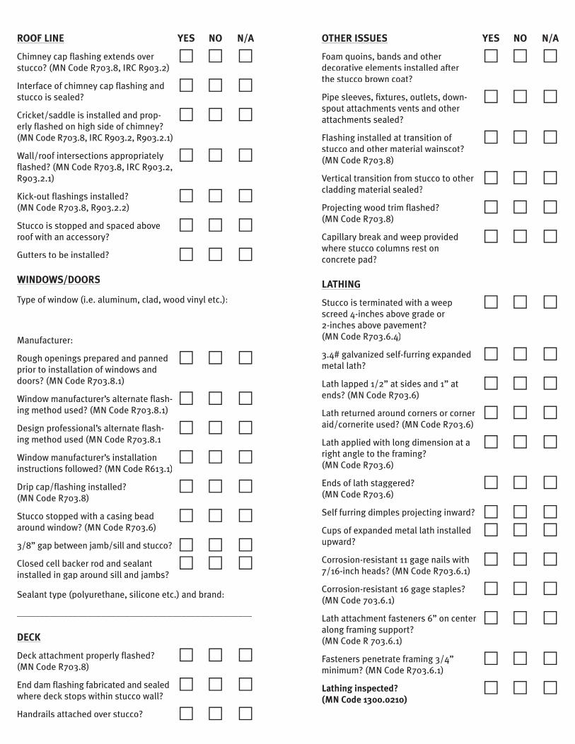
OTHER ISSUES YES NO N/A
Foam quoins, bands and other decorative elements installed after the stucco brown coat?
Pipe sleeves, fi xtures, outlets, down- spout attachments vents and other attachments sealed?
Flashing installed at transition of stucco and other material wainscot? (MN Code R703.8)
Vertical transition from stucco to other cladding material sealed?
Projecting wood trim fl ashed? (MN Code R703.8)
Capillary break and weep provided where stucco columns rest on concrete pad?
LATHING
Stucco is terminated with a weep screed 4-inches above grade or 2-inches above pavement? (MN Code R703.6.4)
3.4# galvanized self-furring expanded metal lath?
Lath lapped 1/2” at sides and 1” at ends? (MN Code R703.6)
Lath returned around corners or corner aid/cornerite used? (MN Code R703.6)
Lath applied with long dimension at a right angle to the framing? (MN Code R703.6)
Ends of lath staggered? (MN Code R703.6)
Self furring dimples projecting inward?
Cups of expanded metal lath installed upward?
Corrosion-resistant 11 gage nails with 7/16-inch heads? (MN Code R703.6.1)
Corrosion-resistant 16 gage staples? (MN Code 703.6.1)
Lath attachment fasteners 6” on center along framing support? (MN Code R 703.6.1)
Fasteners penetrate framing 3/4” minimum? (MN Code R703.6.1)
Lathing inspected? (MN Code 1300.0210)
ROOF LINE YES NO N/A
Chimney cap fl ashing extends over stucco? (MN Code R703.8, IRC R903.2)
Interface of chimney cap fl ashing and stucco is sealed?
Cricket/saddle is installed and prop- erly fl ashed on high side of chimney? (MN Code R703.8, IRC R903.2, R903.2.1)
Wall/roof intersections appropriately fl ashed? (MN Code R703.8, IRC R903.2, R903.2.1)
Kick-out fl ashings installed? (MN Code R703.8, R903.2.2)
Stucco is stopped and spaced above roof with an accessory?
Gutters to be installed?
WINDOWS/DOORSWINDOWS/DOORS
Type of window (i.e. aluminum, clad, wood vinyl etc.):
__________________________________________________
Manufacturer: ______________________________________
Rough openings prepared and panned prior to installation of windows and doors? (MN Code R703.8.1)
Window manufacturer’s alternate fl ash- ing method used? (MN Code R703.8.1)
Design professional’s alternate fl ash- ing method used (MN Code R703.8.1
Window manufacturer’s installation instructions followed? (MN Code R613.1)
Drip cap/fl ashing installed? (MN Code R703.8)
Stucco stopped with a casing bead around window? (MN Code R703.6)
3/8” gap between jamb/sill and stucco?
Closed cell backer rod and sealant installed in gap around sill and jambs?
Sealant type (polyurethane, silicone etc.) and brand:
__________________________________________________
DECK
Deck attachment properly fl ashed? (MN Code R703.8)
End dam fl ashing fabricated and sealed where deck stops within stucco wall?
Handrails attached over stucco?


“ Education is what survivesEducation is what surviveswhen what has been learned when what has been learned
has been forgotten.has been forgotten.”B.F. Skinner, 1964B.F. Skinner, 1964
This document is dedicated to the memory of Art Brisson (1948-2000) who’s honesty and
forthright concern about his industry providedthe impetus for the original publication.
We miss you Art.