in-place hepa filter penetration test - digital library/67531/metadc685409/m2/1/high... · in-place...
TRANSCRIPT
UCRL-JC-127230PRBPRINT
In-Place HEPA Filter Penetration Test
W. BergmanK. WilsonJ. Elliott
B. BettencourtJ.W. Slawski
Thispaperwaspreparedforsubmittalto the24th DOEliVRC Nuclear Air (Waning and Treatment Conference
Portfa& ORJuly15-18, 19%
DISCLAIMER
This document was prepared as an account of work sponsored by an agency ofthe United States Government. Neither the United States Government nor theUniversity of California nor any of their employees, makes any warranty, expressor implied, or assumes any legal liability or responsibility for the accuracy,completeness, or usefulness of any information, apparatus, product, or processdisclosed, or represents that its use would not infringe privately owned rights.Reference herein to any specific commercial product, process, or service by tradename, trademark, manufacturer, or otherwise, does not necessarily constitute orimply its endorsement, recommendation, or favoring by the United StatesGovernment or the University of California. The views and opinions of authorsexpressed herein do not necessarily state or reflect those of the United StatesGovernment or the University of California, and shall not be used for advertisingor product endorsement purposes.
24th DOE/NRC NUCLEAR AIR CLEANING AND TREATMENT
IN-PLACEHEPAFILTERPENETRATIONTESl%
by
W. Bergman, K. Wilson, J. Elliott, B. Bettencourt and J. W. SlawskilLawrence Livermore National Laboratory
Livermore, CA94550
Abstract.
We have demonstrated the feasibility of conducting penetration tests on highefficiency particulate air (HEPA)filters as installed in nuclear ventilation systems.The in-place penetration test, which is designed to yield equivalent penetrationmeasurements as the standard DOP efficiency test, is based on measuring theaerosol penetration of the filter installation as a function of particle size using aportable laser particle counter.(l) This in-place penetration test is compared to thecurrent in-place leak test using light scattering photometers for single HEPAfilterinstallations and for HEPAfilter plenums using the shroud method. Test resultsshow the in-place penetration test is more sensitive than the in-place leak test, hasa similar operating procedure, but takes longer to conduct. Additional tests arerequired to confirm that the in-place penetration test yields identical results as thestandard dioctyl phthalate (DOP) penetration test for HEPAfilters with controlledleaks in the filter and gasket and duct by-pass leaks. Further development of theprocedure is also required to reduce the test time before the in-place penetrationtest is practicaL
I. Introdu ction
Before a HEPAfiltration system can be used in a DOE nuclear facility, theventilation system and the HEPAfalters must pass acceptance tests described inASMEN510 or AG1, and the HEPAfilter must pass the MIL-STD-282 penetration test.(‘‘3) The acceptance tests consist of leak tests of ducts and housings, airflowcapacity and distribution tests, and air-aerosol mixing uniformity tests. Theairflow distribution test is designed to insure that HEPAfilters see a uniform airflow, while the air-aerosol mixing test is performed to insure that theconcentration of aerosols challenging the filter is uniform. This will insure thatrepresentative samples can be obtained before and after the filter for computingthe filter penetration.
1 U.S.Departmentof Energy,DefensePrograms(DP-4S),Germantown,MD20874
*This work was performed under the auspices of the U.S. Department of Energy byLawrence Livermore National Laboratory under contract no. W-7405-ENG- 41 The workwas supportedby DOE’sDefenseProgramOffice of Technical and Environmental Support,DP-45.
1
24th DOE/NRC NUCLEAR AIR CLEANING AND TREATMENT CONFERENCE
The HEPAfilter penetration test is given in MIL-STD-282.(1) This test requiresHEPAfilters to have less than 0.03% penetration for 0.3 pm DOP aerosols asmeasured by a light scattering photometer. The 0.3 ~m aerosols were originallyselected because they were believed to be the most penetrating aerosols and wouldyield the most conservative penetration values for the HEPAfilters. These aerosolswere generated in a very large machine by a controlled condensation of DOP vaporand were thought to be monodisperse.
After the HEPAfilter is installed in a certified ductwork, and once a yearthereafter, the filter installation must be tested for leaks. (2-4) This in-place leaktest is performed to insure that the HEPAfilter is properly installed and has notbeen damaged, that there are no leaks in the mounting frame or between themounting frame and the housing, and that the system contains no bypassing thatwould reduce the system penetration. The in-place leak test is not a filterpenetration test and can not be used in determining the penetration of HEPAfilters. The difference between the two tests is the particle size and the type ofaerosol generator used to challenge the lllte~ the DOP penetration test uses nearmonodisperse 0.3 ~m particles generated by a very large vapor condensationgenerator, while the in-place test uses heterodisperse 0.7 pm particles generated bysmall portable air or thermal generators. ERDA 76-21 recommends anacceptance criterion of 0.03% maximum penetration for the in-place DOP test.(4)
The HEPAfilter leak test was implemented in 1960 in the U.S. to verify that theinstalled filtration systems did not have leaks.(s) This test represented a second-best choice at that time since it was not possible to conduct in-place penetrationtests using the available test equipment. The problem was that the particlemeasuring instruments at that time could not distinguish between particle sizes,and monodisperse 0.3 Lm aerosol generators were not portable. The available light ,scattering photometers were portable but could not distinguish between differentparticle sizes. To measure HEPAfalter penetration at 0.3 ~m diameter, it wasnecessary to have a monodisperse 0.3 Urn diameter generator, which were notportable. The only portable aerosol generators at that time producedheterodisperse aerosols.
Now, a variety of instruments and aerosol generators are commerciallyavailable that can be used for measuring in-place filter penetration. Portableparticle spectrometers are available that can measure specific particle sizes inheterodisperse aerosols. Portable aerosol generators are also available that cangenerate monodisperse aerosols. Thus it is now possible to measure in-place HEPAfilter penetration at 0.3 Vm using portable equipment consisting of either aparticle size spectrometer and a heterodisperse aerosol generator or an integratedparticle analyzer (e.g. photometer, condensation nuclei counter) and amonodisperse aerosol generator. We will only address the in-place penetrationmethod using laser spectrometers and heterodisperse aerosols in this paper.
2

24th DOE/NRC NUCLEAR AIR CLEANING AND TREATMENT CONFERENCE
JI. Difference Between Penetr- In-Place Leak. and In-Place Penetration Tes@
The difference between”the results of the penetration and the in-place leak testscan be illustrated with a typical HEPAfilter penetration curve shown as a functionof particle size in Figure 1. The penetration is a maximum at O.15Lm, decreasesrapidly with increasing particle size and is negligible at 0.7 km for HEPAfilters withno leaks. Although the penetration measurement at 0.3 ~m is significantly lessthan the maximum, it still provides a sensitive measurement of the filterpenetration. In contrast to the in-tact HEPAfilter installation in Figure 1, particlepenetration through leaks is independent of particle size. Thus any penetrationthat is measured at 0.7 Vm diameter during the in-place leak test can ixattributed to leaks.
0.1 1
Diameter, urn
Figure 1. Plot of HEPA filter penetration measurements as a function ofparticle size for dioctyl sebacate (DOS) aerosols with two different laserspectrometers. Nuclear grade, 1,000 cfm HEPA filter.
3
24th DOE/NRC NUCLEAR AIR CLEANING AND TREATMENT CONFERENCE
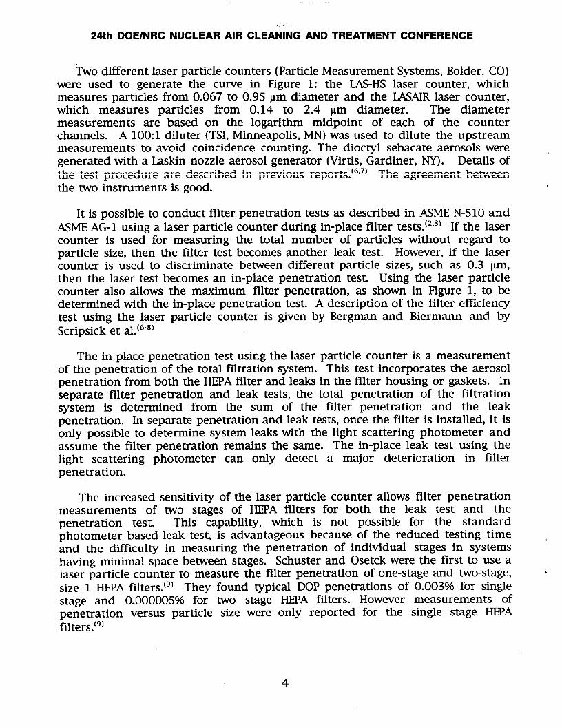
Two different laser particle counters (Particle Measurement Systems, Bolder, CO)were used to generate the curve in Figure 1: the LAS-HS laser counter, whichmeasures particles from 0.067 to 0.95 Mmdiameter and the LASAIRlaser counter,which measures particles from 0.14 to 2.4 pm diameter. The diametermeasurements are based on the logarithm midpoint of each of the counterchannels. A 100:1 diluter (TSI, Minneapolis, MN) was used to dilute the upstreammeasurements to avoid coincidence counting. The dioctyl sebacate aerosols weregenerated with a Laskin nozzle aerosol generator (Virtis, Gardiner, NY). Details ofthe test procedure are described in previous reports. The agreement betweenthe two instruments is good.
It is possible to conduct filter penetration tests as described in ASME N-510 andASMEAG-1 using a laser particle counter during in-place filter tests. (2’3) If the lasercounter is used for measuring the total number of particles without regard toparticle size, then the filter test becomes another leak test. However, if the lasercounter is used to discriminate between different particle sizes, such as 0.3 Km,then the laser test becomes an in-place penetration test. Using the laser particlecounter also allows the maximum filter penetration, as shown in Figure 1, to bedetermined with the in-place penetration test. A description of the filter efficiencytest using the laser particle counter is given by Bergman and Biermann and byScripsick et al.(G”8)
The in-place penetration test using the laser particle counter is a measurementof the penetration of the total filtration system. This test incorporates the aerosolpenetration from both the HEPAfilter and leaks in the filter housing or gaskets. Inseparate filter penetration and leak tests, the total penetration of the filtrationsystem is determined from the sum of the filter penetration and the leakpenetration. In separate penetration and leak tests, once the filter is installed, it isonly possible to determine system leaks with the light scattering photometer andassume the filter penetration remains the same. The in-place leak test using thelight scattering photometer can only detect a major deterioration in filterpenetration.
The increased sensitivity of the laser particle counter allows filter penetrationmeasurements of two stages of HEPA filters for both the leak test and thepenetration test. This capability, which is not possible for the standardphotometer based leak test, is advantageous because of the reduced testing timeand the difficulty in measuring the penetration of individual stages in systemshaving minimal space between stages. Schuster and Osetck were the first to use alaser particle counter to measure the filter penetration of one-stage and two-stage,size 1 HEPAfilters.(g) They found typical DOP penetrations of 0.003°A for singlestage and 0.000005% for two stage HEPA filters. However measurements ofpenetration versus particle size were only reported for the single stage HEPAfilters.(g)
24th DOE/NRC NUCLEAR AIR CLEANING AND TREATMENT CONFERENCE
Ortiz determined the filter leaks in a number of 20,000 cfm two-stage HEPAfilter systems. He did not discriminate between particle size, but rather usedthe total particle count before and after the filters to determine the system leaks.The test was therefore a leak test and not a penetration test. The leakmeasurements for ten systems varied from 0.0067% to 0.00000009%. Themaximum allowable leakage for two stage HEPAfilters is 0.000009%. This studywas significant not only because the test system was demonstrated under fieldconditions, but also because it showed the laser particle counter detected filtersystem failures that were not seen with the standard single stage method describedin ASMEN510.(2)
Ortiz et al also conducted a round robin test of two-stage HEPAfiltration systemin which they measured filter penetration as a function of particle size using alaser spectrometer.(n) In this configuration, the filter test was an in-placepenetration test. To avoid coincidence counting, the upstream concentration wasdiluted. The test apparatus and procedure were incorporated into an ASTM testmethod for evaluating HEPAfilters.
The Los Alamos National Laboratory (LANL) uses a laser spectrometer andheterodisperse aerosols as developed by Ortiz and incorporated in the ASTMstandard for conducting in-place HEPAfilter leak tests in all of their facilities.(1°-13JSince the particle measurements are made by adding all of the sizes into a singlecount, the LANLin-place filter measurements can not be used for determining filterpenetration, but rather for leaks. Adding together the particle counts in thedifferent particle size bins destroys the ability to measure filter penetration withheterodisperse aerosols. However, by keeping the particle counts in the differentsize bins separate, the LANLtest procedure for leaks can be converted to a test offilter penetration test.
111. Correlation of In-Place Penetration Test With Standard Penetration Test
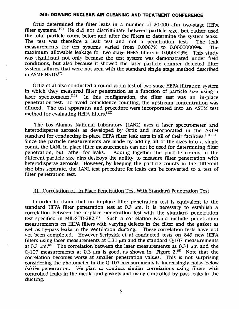
In order to claim that an in-place filter penetration test is equivalent to thestandard HEPA filter penetration test at 0.3 ~m, it is necessary to establish acorrelation between the in-place penetration test with the standard penetrationtest specified in MIL-STD-282.(1) Such a correlation would include penetrationmeasurements on HEPAfilters with varying defects in the filter and the gasket aswell as by-pass leaks in the ventilation ducting. These correlation tests have notyet been completed. However Scripsick et al conducted tests on 849 new HEPAfilters using laser measurements at 0.31 Lm and the standard Q-107 measurementsat O 3 ~m.(8) The correlation between the laser measurements at 0.31 ~m and theQ-107 measurements at 0.3 pm is good, as shown in Figure 2.(6) Note that thecorrelation becomes worse at smaller penetration values. This is not surprisingconsidering the photometer in the Q-107 measurements is increasingly noisy below0.01% penetration. We plan to conduct similar correlations using filters withcontrolled leaks in the media and gaskets and using controlled by-pass leaks in theducting.
5

24th DOE/NRC NUCLEAR AIR CLEANING AND TREATMENT CONFERENCE
0.1
0.01
o
0
3
. . . .. .. . . . . . .. .. .....rv;
o0 0
[
-c”m,
~~l!o
,0
0
5A v
6 0
,.. I00010.001 0.01
Q107 Penetration at 0.30 pm, %
Figure 2. ~o~elation of HEpA filter pene~ation be~een laser s~e~~ometer andQ107 ~hotometer.(s)
For measurements of the maximum filter penetration, it is not necessary toconduct correlation tests with the Q107 tester because it only measures thepenetration at 0.3 km. The Q107 can not be used to determine the maximumfilter penetration at 0.15 }m, as seen in Figure 1. In fact, there are no standardreference tests for the maximum filter penetration. The laser spectrometer can beused in a primary test standard for the maximum filter penetration if the particlesize range is sufficient to clearly show a maximum as seen in Figure 1.
IV. Correlation of In-Place Penetration Test With Standard Leak Test
We have conducted a series of filter penetration tests on a HEPAfilter with anincreasing number of pin holes to establish a correlation between the in-placepenetration test and the standard leak test. A nuclear grade, 1,000 cfm HEPA filterwas used in these correlation tests. Two different laser spectrometers were used to
6
24th DOE/NRC NUCLEAR AIR CLEANING AND TREATMENT CONFERENCE
determine the in-place filter penetration as a function of size: the LAS-HS lasercounter, which measures particles from 0.067 to 0.95 ~m diameter and the LASAIRlaser counter, which measures particles from 0.14 to 2.4 pm diameter. A 100:1diluter (TSI, Minneapolis, MN) was used to dilute the upstream measurements toavoid coincidence counting. The dioctyl sebacate aerosols used in the in-placepenetration tests were generated with a Laskin nozzle aerosol generator (Virtis,Gardiner, NY). Filter penetration was determined from the ratio of thedownstream concentration divided by the upstream concentration after correctingfor the upstream dilution and subtracting background aerosols. Figure 1 shows thepenetration of the new HEPAfilter as a function of particle size.
The standard leak test was conducted using a TDA-2GN light scatteringphotometer (ATI, Owings Mills, MD) to obtain aerosol measurements before andafter the HEPAfilter. A TDA-5B aerosol generator (ATI, Owings Mills, MD) was usedto generate the alpha-olefin (Emery 3004) aerosols for the in-place leak tests. Filterleak measurements were made by electronically setting the photometer upstreamconcentration to 10WOand reading the downstream concentration directly. Thein-place leak test yielded a leak of 0.01% for the test shown in Figure 1.
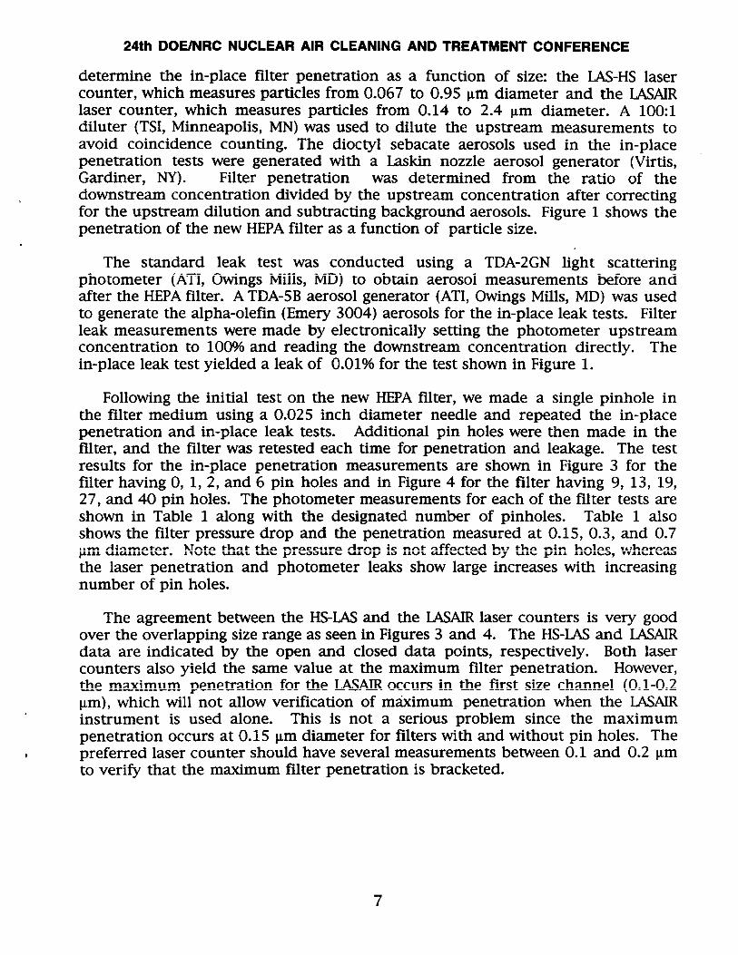
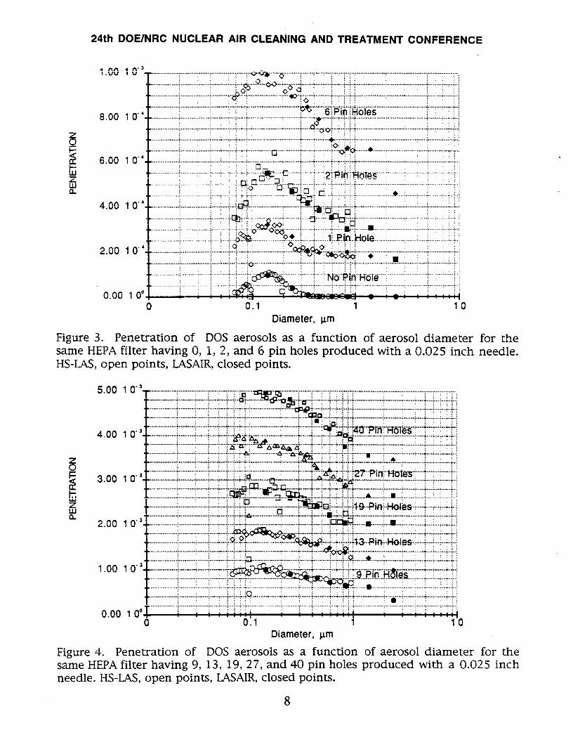
Following the initial test on the new HEPAfilter, we made a single pinhole inthe filter medium using a 0.025 inch diameter needle and repeated the in-placepenetration and in-place leak tests. Additional pin holes were then made in thefalter, and the filter was retested each time for penetration and leakage. The testresults for the in-place penetration measurements are shown in Figure 3 for thefilter having O, 1, 2, and 6 pin holes and in Figure 4 for the filter having 9, 13, 19,27, and 40 pin holes. The photometer measurements for each of the filter tests areshown in Table 1 along with the designated number of pinholes. Table 1 alsoshows the filter pressure drop and the penetration measured at 0.15, 0.3, and 0.7pm diameter. Note that the pressure drop is not affected by the pin holes, whereasthe laser penetration and photometer leaks show large increases with increasingnumber of pin holes.
The agreement between the HS-LASand the LASAIRlaser counters is very goodover the overlapping size range as seen in Figures 3 and 4. The HS-LASand LASAIRdata are indicated by the open and closed data points, respectively. Both lasercounters also yield the same value at the maximum filter penetration. However,the maximum penetration for the LASAIRoccurs in the first size channel (0.1-0.2~m), which will not allow verification of m~imum penetration when the LASAIRinstrument is used alone. This is not a serious problem since the maximumpenetration occurs at 0.15 Vm diameter for filters with and without pin holes. The
, preferred laser counter should have several measurements between 0.1 and 0.2 Lmto verify that the maximum filter penetration is bracketed.
24th DOE/NRC NUCLEAR AIR CLEANING AND TREATMENT CONFERENCE
1.00
8.00
6.00
4.00
2.00
0.00
1 o“
10
,C; ;:!,.. . . ....... . ., .*. .
:?..... j :..{ ...7.
!: W?-4?$co 0.1 1 10
Diameter, pm
Figure 3. pene~ation of D(JS aerosols as a function of aerosol diameter for thesame HEPAfilter having O, 1, 2, and 6 pin holes produced with a 0.025 inch needle.HS-LAS,open points, LASAIR,closed points.
8
24th DOE/NRC NUCLEAR CLEANING AND TREATMENT
.
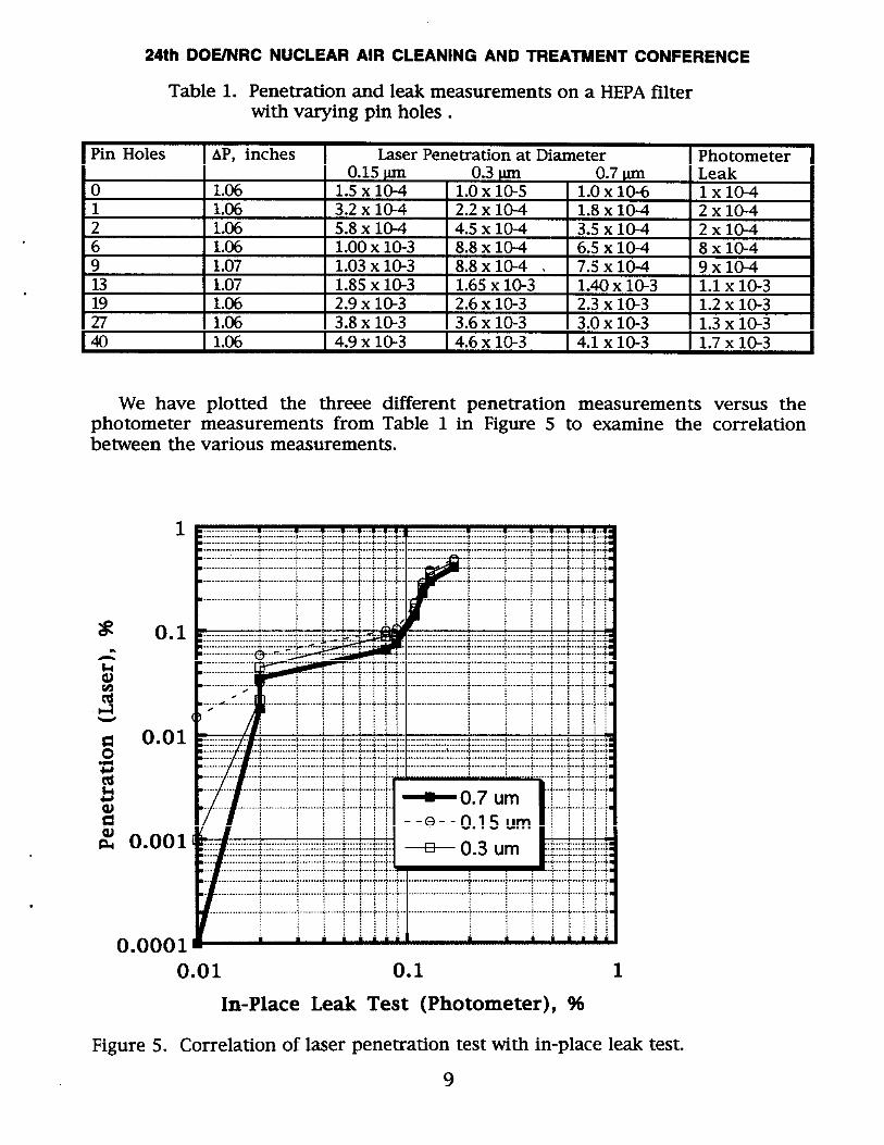
Table 1. Penetration and leak measurements on a HEPAfilterwith varying pin holes .
Pin Holes AP, inches LaserPenetrationat Diameter Photometer0.15 @ 0.3 @ 0.7 m Leak
o 1.06 1.5 x 10⁻⁴ 1.0 x 10⁻⁵ 1.0 X10⁻⁶ 1 x 10-41 1.06 3.2 X10⁻⁴ 2.2 x 10⁻⁴ 1.8 x 10⁻⁴ 2X1 O-42 1.06 5.8 X10⁻⁴ 4.5 x 10⁻⁴ 3.5 x 10⁻⁴ 2X1 O-46 1.06 1.00 x 10⁻³ 8.8 x 10⁻⁴ 6.5 X10⁻⁴
,9 1.078 X10⁻⁴
1.03 x 10⁻³ 8.8 x 10⁻⁴ . 7.5 x 10⁻⁴ 9X1O-413 1.07 1.85 X10⁻³ 1.65 X10⁻³ 1.40 x 10⁻³ 1.1 x 10-319 1.06 2.9 X10⁻³ 2.6 X10⁻³ 2.3 X10⁻³ 1.2 x 10-327 1.06 3.8 X10⁻³ 3.6 X10⁻³ 3.0 x 10⁻³ 1.3 x 10-340 1.06 4.9 x 10⁻³ 4.6 X10⁻³ 4.1 x 10⁻³ 1.7 x 10⁻³
We have plotted the threee different penetration measurementsphotometer measurements from Table 1 in Figure 5 to examine thebetween the various measurements.
1
0.1
0.01
0.001
0.0001
I=----:.*
I .........+...........!.::~;
.......
0.01 0.1 1In-Place Leak Test (Photometer), %
Figure 5. Correlation of laser penetration test with in-place leak test.
9
versus thecorrelation
24th DOE/NRC NUCLEAR AIR CLEANING AND TREATMENT CONFERENCE
In general, there is poor correlation between the photometer leak and the laserpenetration measurements, even for the 0,7~m data, which is supposed torepresent the average size of the test aerosol in the photometer test. One of thereasons for the poor correlation is the lack of sensitivity of the photometer forpenetration measurements less than 0.01%. However, the major reason for thepoor correlation between the photometer leak and the laser penetrationmeasurements is due to the fundamental difference between differential andintegrated size measurements with heterodisperse aerosols. Bergman andBiermann have shown that large variations in the photometer measurements arepossible compared to laser or condensation nuclei counters depending on thedegree of aerosol heterodispersion and the extent of filter leaks. (7314)Figure 5 alsoshows that the photometer measurements, although still not satisfacto~, correlatebetter with the maximum penetration measurements at 0.15 pm than with themeasurements at 0.3 or 0.7 pm. The lack of correlation between the in-placepenetration test and the in-place leak test illustrates that the present leak testprovides only an approximate measure of the sytem penetration.
V. Field EvaluaH“on of In-Place Penetration and In-Place Leak Tests
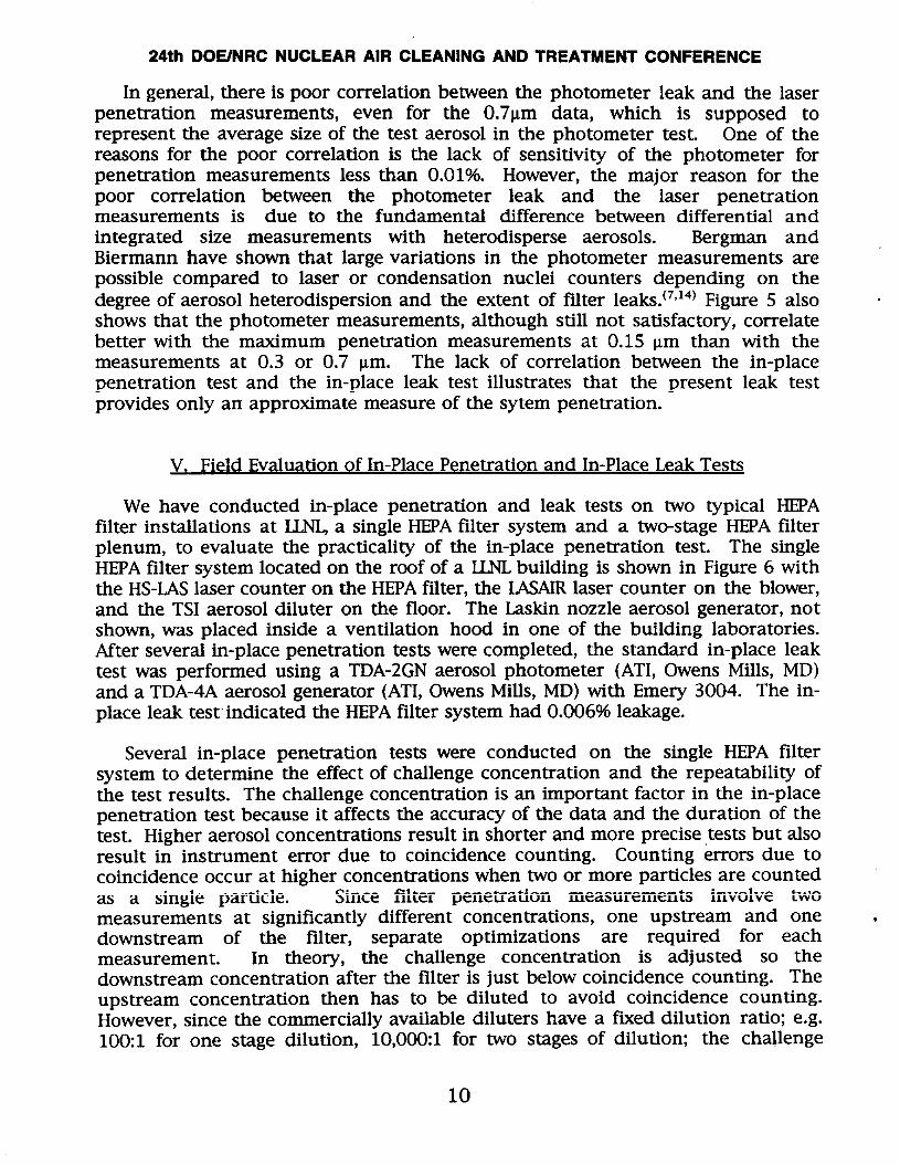
We have conducted in-place penetration and leak tests on two typical HEPAfilter installations at LLNI+a single HEPAfilter system and a two-stage HEPAfilterplenum, to evaluate the practicality of the in-place penetration test. The singleHEPAfilter system located on the roof of a UN, building is shown in Figure 6 withthe HS-LASlaser counter on the HEPAfilter, the LASAIRlaser counter on the blower,and the TSI aerosol diluter on the floor. The Laskin nozzle aerosol generator, notshown, was placed inside a ventilation hood in one of the building laboratories.After several in-place penetration tests were completed, the standard in-place leaktest was performed using a TDA-2GN aerosol photometer (ATI, Owens Mills, MD)and a TDA-4A aerosol generator (ATI, Owens Mills, MD) with Emery 3004. The in-place leak test”indicated the HEPAfilter system had 0.006% leakage.
Several in-place penetration tests were conducted on the single HEPA filtersystem to determine the effect of challenge concentration and the repeatability ofthe test results. The challenge concentration is an important factor in the in-placepenetration test because it affects the accuracy of the data and the duration of thetest. Higher aerosol concentrations result in shorter and more precise tests but alsoresult in instrument error due to coincidence counting. Counting errors due tocoincidence occur at higher concentrations when two or more particles are countedas a single particle. Since filter penetration measurements involve twomeasurements at significantly different concentrations, one upstream and onedownstream of the filter, separate optimization are required for eachmeasurement. In theory, the challenge concentration is adjusted so thedownstream concentration after the filter is just below coincidence counting. Theupstream concentration then has to be diluted to avoid coincidence counting.However, since the commercially available diluters have a fixed dilution ratio; e.g.100:1 for one stage dilution, 10,000:1 for two stages of dilution; the challenge
10
24th DOE/NRC NUCLEAR AIR CLEANING AND TREATMENT CONFERENCE
concentration must be adjusted to avoid coincidence in both the upstream(challenge) and downstream measurements.
.——.
Figure 6. Photograph of the in-place penetration test apparatus on a single HEPAfilter system using laser counters. The HS-LASlaser counter is on the HEPAfilter, theLASAIRlaser”counter on the blower, and the TSI aerosol diluter on the floor.
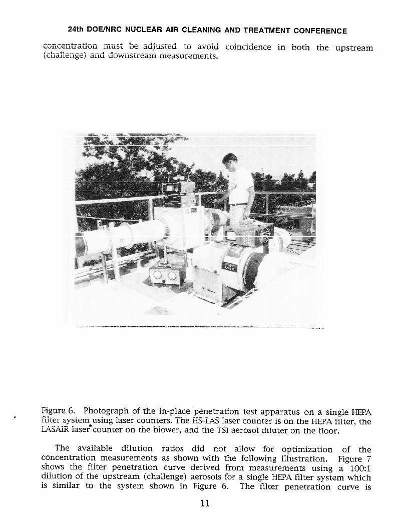
The available dilution ratios did not allow for optimization of theconcentration measurements as shown with the following illustration. Figure 7shows the filter penetration curve derived from measurements using a 100:1dilution of the upstream (challenge) aerosols for a single HEPAfilter system whichis similar to the system shown in Figure 6. The filter penetration curve is
11
24th DOE/NRC NUCLEAR AIR CLEANING AND TREATMENT CONFERENCE
extremely noisy, even with a 1 minute upstream and a 15 minute downstreamsample, because the low downstream aerosol concentration is at the backgroundlevel. This resulted from reducing the challenge concentration to avoidcoincidence counting. Increasing the sampling time did not help in this casebecause the measurement of background aerosols also increased. Using a 10,00Ckldiluter on the upstream sample significantly improved the precision of the dataand also reduced the sampling time as seen in Figure 8. The upstream anddownstream sample times for that test were 2 and 6 minutes, respectively. Anoptimized diluter between 1,0001 and 2,000:1 would reduce the sample time toabout 1 minute for each measurement. The optimized diluter and associatedcalibration procedure must be developed before the in-place penetration method isadopted for routine measurements.
AP=1.1O’’H2O
Diameter, j-m
Figure 7. Filter penetration as a function of aerosol diameter for a single HEPAfiltersystem using the in-place penetration measurement with a 1001 diluter. Opendata was generated with HS-LAS,closed data with LASAIR. In-place leak test with a
photometer was 6 x 10⁻⁵.
12
24th DOE/NRC NUCLEAR AIR CLEANING AND TREATMENT
AP=1.1O’’H2O
6.00 10’6y- ...............-v......r...n......F.L.o.w=.l.!.oo.cF.M. .......v.................................... .
Diameter, pm
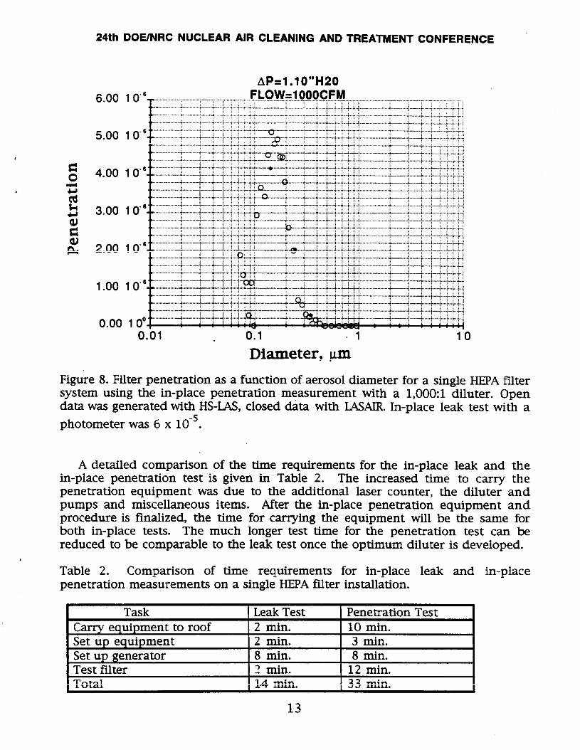
Figure 8. Filter penetration as a function of aerosol diameter for a single HEPAfiltersystem using the in-place penetration measurement with a 1,000:1 diluter. Opendata was generated with HS-LAS,closed data with LASAIR.In-place leak test with a
photometer was 6 x 10⁻⁵.
A detailed comparison of the time requirements for the in-place leak and thein-place penetration test is given in Table 2. The increased time to carry thepenetration equipment was due to the additional laser counter, the diluter andpumps and miscellaneous items. After the in-place penetration equipment andprocedure is finalized, the time for carrying the equipment will be the same forboth in-place tests. The much longer test time for the penetration test can bereduced to be comparable to the leak test once the optimum diluter is developed.
Table 2. Comparison of time requirements for in-place leak and in-placepenetration measurements on a single HEPAfilter installation.
Task Leak Test Penetration Testcarryequipment to roof 2 min. 10 min.Set up equipment 2 min. 3 min.Set up generator 8 min. 8 min.Test filter 2 min. 12 min.Total 1.4 min. 33 min.
13
24th DOE/NRC NUCLEAR AIR CLEANING AND TREATMENT CONFERENCE
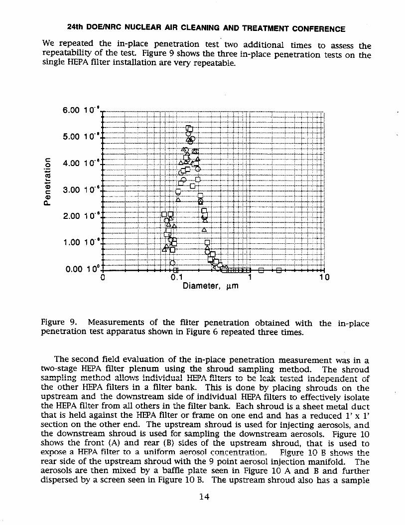
We repeated the in-place penetration test two additional times to assess therepeatability of the test. Figure 9 shows the three in-place penetration tests on thesingle HEPAfilter installation are very repeatable.
Figure 9. Measurements of the filter penetration obtained with the in-placepenetration test apparatus shown in Figure 6 repeated three times.
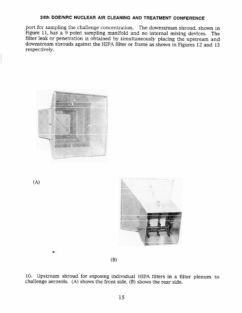
The second field evaluation of the in-place penetration measurement was in atwo-stage I-EPA filter plenum using the shroud sampling method. The shroudsampling method allows individual HEPAfalters to be leak tested independent ofthe other HEPAfilters in a filter bank. This is done by placing shrouds on theupstream and the downstream side of individual I-HA filters to effectively isolatethe HEPAfilter from all others in the filter bank. Each shroud is a sheet metal ductthat is held against the HEPAfilter or frame on one end and has a reduced 1‘ x 1’section on the other end. The upstream shroud is used for injecting aerosols, andthe downstream shroud is used for sampling the downstream aerosols. Figure 10shows the front (A) and rear (B) sides of the upstream shroud, that is used toexpose a HEPAfilter to a uniform aerosol concentration. Figure 10 B shows therear side of the upstream shroud with the 9 point aerosol injection manifold. Theaerosols are then mixed by a baffle plate seen in Figure 10 A and B and furtherdispersed by a screen seen in Figure 10 B. The upstream shroud also has a sample
14
24th DOE/NRC NUCLEAR AIR CLEANING AND TREATMENT CONFERENCE
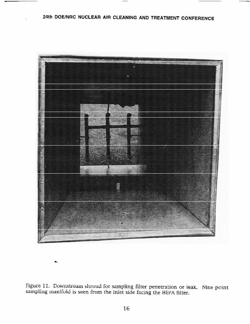
port for sampling the challenge concentration. The downstream shroud, shown inFigure 11, has a 9 point sampling manifold and no internal mixing devices. Thefilter leak or penetration is obtained by simultaneously placing the upstream anddownstream shrouds against the HEPAfilter or frame as shown in Figures 12 and 13respectively.
(A)
*,
(B)
10. Upstream shroud for exposing individual HEPAfilters in a filter plenum tochallenge aerosols. (A) shows the front side, (B) shows the rear side.
15
24th DOE/NRC NUCLEAR AIR CLEANING AND TREATMENT CONFERENCE
!+..
Figure 11. Downstream shroud for sampling filter penetration or leak. Nine pointsampling manifold is seen from the inlet side facing the HEPA filter.
16

.
.
24th DOE/NRC NUCLEAR AIR CLEANING AND TREATMENT CONFERENCE
Figure 12. Downstream shroud forsampling aerosol penetration fromindividual filter. In-place penetra-tion equipment used in this test.
Figure 13. Upstream shroud forgenerating challenge aerosols.Laskin nozzle aerosol generatorused in this test.
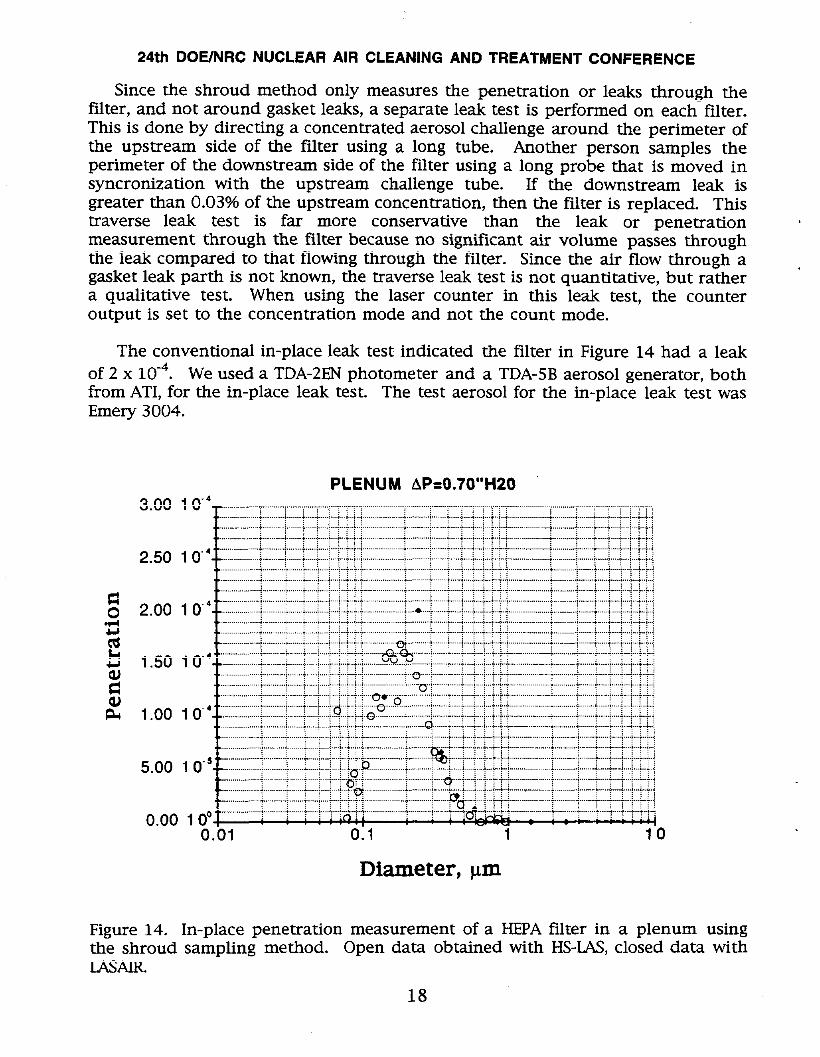
The result of the in-place penetration measurement on one filter in the plenumis shown in Figure 14. We were unable to generate the required high concentrationof challenge aerosols to use the 10,000:1 diluter because the compressor shown inFigure 13 could not supply sufficient pressure to the Laskin nozzle aerosolgenerator. As a result, we used the 100:1 diluter with a lower aerosolconcentration. This resulted in lower precision and a longer sampling time thanwould be required with a higher aerosol concentration and a 10,000:1 diluter. Theupstream and downstream sample times were 2 and 8 minutes, respectively. Theequipment used for the in-place penetration measurement using the shroudmethod was the same as previously described for the single filter test.
17
24th DOE/NRC NUCLEAR AIR CLEANING AND TREATMENT CONFERENCE
Since the shroud method only measures the penetration or leaks through thefilter, and not around gasket leaks, a separate leak test is performed on each filter.This is done by directing a concentrated aerosol challenge around the perimeter ofthe upstream side of the filter using a long tube. Another person samples the
perimeter of the downstream side of the filter using a long probe that is moved insynchronization with the upstream challenge tube. If the downstream leak isgreater than 0.03% of the upstream concentration, then the filter is replaced. Thistraverse leak test is far more conservative than the leak or penetrationmeasurement through the filter because no signtilcant air volume passes throughthe leak compared to that flowing through the filter. Since the air flow through agasket leak parth is not known, the traverse leak test is not quantitative, but rathera qualitative test. When using the laser counter in this leak test, the counteroutput is set to the concentration mode and not the count mode.
The conventional in-place leak test indicated the filter in Figure 14 had a leakof 2 x 10⁻⁴. We used a TDA-2ENphotometer and a TDA-5B aerosol generator, bothfrom ATI, for the in-place leak test. The test aerosol for the in-place leak test wasEmery 3004.
PLENUM AP=O.70’’H2O
Figure 14. In-place penetration measurement of a HEPAfilter in a plenum usingthe shroud sampling method. Open data obtained with HS-IAS, closed data withLASm.
18
24th DOE/NRC NUCLEAR AIR CLEANING AND TREATMENT CONFERENCE
.
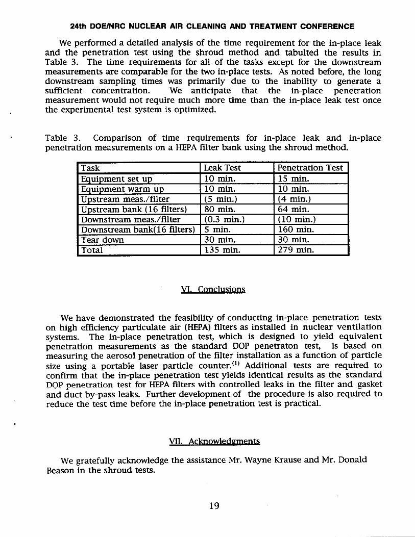
We performed a detailed analysis of the time requirement for the in-place leakand the penetration test using the shroud method and tabulted the results inTable 3. The time requirements for all of the tasks except for the downstreammeasurements are comparable for the two in-place tests. As noted before, the longdownstream sampling times was primarily due to the inability to generate asufficient concentration. We anticipate that the in-place penetrationmeasurement would not require much more time than the in-place leak test oncethe experimental test system is optimized.
Table 3. Comparison of time requirements for in-place leak and in-placepenetration measurements on a HEPAfilter bank using the shroud method.
] Task ] Leak Test ] Penetration Test [Equipment set up 10 min. 15 min.Equipment warm up 10 min. 10 min.Upstream mess./filter (5 min.) (4 min.)Upstreti bank (16 filters) I WI min. I 64 min.
Downstream mess./filter --ln....-.--—— L.-.-l. f3L 01
1~dr UUWI1 I o u 11111,
Total I 135 mi
------- ------ .
.- iO.3min.) (1O min.)I-JUWIH.I CdUl UtiIA1 ~ v Aers) 5 min. 160 min.m-. —A----- ?n —: no 30 min.
,in. I 279 min. I
VI. Conclusions
We have demonstrated the feasibility of conducting in-place penetration testson high efficiency particulate air (HEPA)filters as installed in nuclear ventilationsystems. The in-place penetration test, which is designed to yield equivalentpenetration measurements as the standard DOP penetration tesL is based onmeasuring the aerosol penetration of the filter installation as a function of particlesize using a portable laser particle counter.(l) Additional tests are required toconfirm that the in-place penetration test yields identical results as the standardDOP penetration test for HEPAfilters with controlled leaks in the filter and gasketand duct by-pass leaks. Further development of the procedure is also required toreduce the test time before the in-place penetration test is practical.
*
VU, Acknowled~men~
We gratefully acknowledge the assistance Mr. Wayne Krause and Mr. DonaldBeason in the shroud tests.
19
24th DOE/NRC NUCLEAR AIR CLEANING AND TREATMENT CONFERENCE
VII . References
1. MIL-STD-282 Filter Units, Protective Clothing, Gas-Mask Components andRelated Products: Performance-Test Methods, Method 105.9, Military StandardMIL-STD-282, Commanding Ofllcer, Frankford Arsenal, Navy Department, A’ITN:SMUFA-N1100, Philadelphia, PA, 19137, (1974)
2. American Society of Mechanical Engineers, “Testing of Nuclear Air TreatmentSystems”, ASME Standard N51O-1989, The American Society of Mechanical ,Engineers, 345 47th Street, NewYork, N.Y. 10017, (1989)
3. American Society of Mechanical Engineers , Code on Nuclear Air and GasTreatment, ASME AG1-1994, The American Society of Mechanical Engineers, 34547th Street, NewYork, N.Y. 10017, (1989)
4. Burchsted, CA, Kahn, JE, and Fuller, AB, “Nuclear Air Cleaning Handbook”, ERDA76-21, National Technical Information Service, 5285 Fort Royal Rd, Springfield, VA22161, (1976).
5. Parrish, EC and Schneider, RW, “Review of inspection and testing ofhigh-efficiency particulate air filters at ORNL”, in Treatment ofRadioactive Wastes, International Atomic Energy Agency, Vienna, pp(1968)
installedAirborne243-264,
6. W. Bergman, A. Biermann, W. Kuhl, B. Lure, A. Bogdanoff, H. Hebard, M. Hall,D. Banks, M. Mazumder, and J. Johnson, “Electric Air Filtration: Theory, LaboratoryStudies, Hardware Development, and Field Evaluations”, LLNLReport, UCID-19952.January 9, (1984)
7. W. Bergman and A. Biermann, “Effect of DOP Hetero-dispersion on HEPAFilterPenetration Measurements,” in Proceedings of 18th DOE Nuclear Airborne WasteNianagement and Air Cleaning Conference, Baltimore, MD, Aug. 12-16, 1984, pp.327-437, NTIS,Springfield, VA,CONF-840806, (1985)
8. Scripsick, R.c., Smitherman, R.L., and McNabb, S.A. “operational evaluation .of the High Flow Alternative Filter Test System” Proceedings of 19th DOE/NRCNuclear Air Cleaning Conference, CONF-860820, National Technical InformationService, Springfield, VA 22161, pp 863-889, (1987).
9. Schusster, B and Osetek, D, “The use of a single particle intra-cavity laserparticle spectrometer for measurements of HEPAfilters and filter systems” 14thERDAAir Cleaning Conference, P.528, CONF-760822, NTIS, Springfield, VA, (1977).
20
24th DOE/NRC NUCLEAR AIR CLEANING AND TREATMENT CONFERENCE
10. Ortiz, J, “In-place testing of multiple stage filter systems without disruptionof plant operations in the plutonium facility at Los Alamos, 18th DOE NuclearAirborne Waste Management and Air Cleaning Conference, CONF-840806,NTIS,Springfield, VA, p. 209, (1985).
11. Ortiz, J, Biermann, A, and Nicholson, R, “Preliminary test results of a roundrobin test program to evaluate a nulti-stage HEPA filter system using singleparticle size counts” in Advances in Filtration and Separation Technology, 4, 213,American Filtration Society, Gulf Publishing Co., Houston, Texas (1991 ).
12. ASTM Standard Test Method for “Air cleaning performance of a high-efficiency particulate air filter system”, F-147 1-93, ASTM, 1916 Race St.Philadelphia, PA, 19103, (1993).
13. Martinez, V. “’Procedure for in-place filter testing” Los Alamos NationalLaboratory, Operating Manual, (1995).
14. Biermann, AH and Bergman, W, “Filter penetration measurements using acondensation nuclei counter and an aerosol photometer” J. Aerosol Sci., Vol. 19,No. 4, pp 471-483, (1988).
21
Technical Inform
ation Departm
ent • Lawrence Liverm
ore National Laboratory
University of C
alifornia • Livermore, C
alifornia 94551