ims automation programmer’s reference and operator’s...
TRANSCRIPT

Tivoli® System Automation for z/OS
IMS Automation Programmer’s Reference and Operator’s Guide
Version 3 Release 1
SC33-8268-02
���


Tivoli® System Automation for z/OS
IMS Automation Programmer’s Reference and Operator’s Guide
Version 3 Release 1
SC33-8268-02
���

Note!
Before using this information and the product it supports, be sure to read the general information under “Notices” on page
ix.
Third Edition (July 2006)
This edition applies to IBM Tivoli System Automation for z/OS (5698-SA3) Version 3 Release 1, an IBM licensed
program, and to all subsequent releases and modifications until otherwise indicated in new editions.
Order publications through your IBM representative or the IBM branch office serving your locality. Publications are
not stocked at the address given below.
A form for readers’ comments appears at the back of this publication. If the form has been removed, address your
comments to:
IBM Deutschland Entwicklung GmbH
Department 3248
Schoenaicher Strasse 220
D-71032 Boeblingen
Federal Republic of Germany
FAX: (Germany) 07031-16-3456
FAX: (Other countries) (+49)+7031-16-3456
Internet: [email protected]
When you send information to IBM, you grant IBM a nonexclusive right to use or distribute the information in any
way it believes appropriate without incurring any obligation to you.
© Copyright International Business Machines Corporation 1990, 2006. All rights reserved.
US Government Users Restricted Rights – Use, duplication or disclosure restricted by GSA ADP Schedule Contract
with IBM Corp.

Contents
Figures . . . . . . . . . . . . . . . v
Tables . . . . . . . . . . . . . . . vii
Notices . . . . . . . . . . . . . . . ix
Programming Interface Information . . . . . . ix
Trademarks . . . . . . . . . . . . . . ix
About This Book . . . . . . . . . . . xi
Who Should Use This Book . . . . . . . . . xi
What’s in This Book . . . . . . . . . . . xi
Related Publications . . . . . . . . . . . xi
The System Automation for z/OS Library . . . xi
Related Product Information . . . . . . . xii
Using LookAt to look up message explanations xii
Part 1. Introducing IMS Automation 1
Chapter 1. Special Functions of IMS
Automation . . . . . . . . . . . . . 3
Recovery of Application Components . . . . . . 3
Program-to-Program Interface . . . . . . . . 3
FDR Environment . . . . . . . . . . . . 3
Functional Overview . . . . . . . . . . 3
IMS Message Processing . . . . . . . . . . 4
Part 2. Customizing IMS Automation 5
Chapter 2. Customizing IMS Automation 7
IMS Automation Definitions . . . . . . . . . 7
Step 1: Provide Basic IMS Automation Common
Policy Definitions . . . . . . . . . . . . 7
Step 2: Define IMS Regions . . . . . . . . 8
Step 3: Code the Entries for OLDS . . . . . . 11
Step 4: Code the Entries for MSC Links . . . . 11
Step 5: Code the Entries for RECONs Recovery 11
Step 6: Code the Entries for Transaction and
Program Recovery . . . . . . . . . . . 12
Step 7: Extended IMS Automation Definitions . . 12
Step 8 (Optional): Preparing IMS Automation to
Manage an IMS XRF System . . . . . . . . 12
Step 9 (Optional): Defining NetView PPI Receiver
Task . . . . . . . . . . . . . . . . 13
Step 10 (Optional): Defining IMS PPI Receiver
Task . . . . . . . . . . . . . . . . 13
Installing the IMS Message Exits . . . . . . . 13
z/OS Exit Router Information . . . . . . . 13
Using the SA z/OS Exit without the z/OS Exit
Router . . . . . . . . . . . . . . . 14
Calling the SA z/OS Exit from Your DFSAOE00
Module . . . . . . . . . . . . . . . 14
Using the IMS Automation Message Policy . . . . 15
Defining IMS Messages . . . . . . . . . 15
Refreshing policy data . . . . . . . . . . 16
Chapter 3. How to Set Up the Special
Functions of IMS Automation . . . . . 17
Special Start and Stop Dependencies . . . . . . 17
General Restrictions . . . . . . . . . . 17
Defining an FDR Environment . . . . . . . 17
How to Automate Startup and Shutdown of IMS
Regions . . . . . . . . . . . . . . . . 18
Startup . . . . . . . . . . . . . . . 18
Shutdown . . . . . . . . . . . . . . 19
IMSPlex Support Subsystems . . . . . . . 23
Automating Recovery for Application Components 23
How to Define Transaction Recovery . . . . . 24
How to Set Up the State/Action Tables . . . . . 27
Adding Local Applications to the IMS Automation
Operator Interface . . . . . . . . . . . . 29
Chapter 4. MESSAGES/USER DATA
Entries for IMS Automation . . . . . . 33
IMS-Specific MESSAGES/USER DATA Keywords . 33
ABCODEPROG—Respond to BMP Region
Abends . . . . . . . . . . . . . . . 34
ABCODES—Restart control region after abend . 36
ABCODETRAN—Transaction Abend Recovery 37
ACORESTART—Agent Restart . . . . . . . 39
BRO—Broadcast a Message Prior to Shutdown 40
CHE—Issue a Checkpoint Command . . . . . 41
CQS0031A—Confirm CQS Restart for Structure 42
CQS0032A—Respond to CQS Structure Restart 43
CQS0033A—Respond to Client Takeover Restart 44
CQSET—Issue Structure Checkpoint at CQS
Termination . . . . . . . . . . . . . 45
DFS2142—Respond to Stopped Logical Link Path
Message . . . . . . . . . . . . . . 46
DFS2161I—Link Stopped by Other System . . . 47
DFS2169I—Respond to MSC Link Disconnection
Message . . . . . . . . . . . . . . 48
DFS3258A—No Online Data Sets Available . . . 49
DFS554A—Respond to Program Abend . . . . 50
DFS690A—Shut Down Dependent Regions when
no Control Region Is Active . . . . . . . . 52
DFS810A—Define Restart Commands . . . . 53
DFS989I—Define Restart Commands (DBCTL
Only) . . . . . . . . . . . . . . . 55
DFS994I—Respond to Checkpoint Written to the
IMS Log . . . . . . . . . . . . . . 57
HOLDQ—Issue Commands at Shutdown . . . 58
IMSINFO—Display Information . . . . . . 59
OLDS—Define Recovery Criteria for OLDS . . . 60
POSTCHKP—Issue Commands after IMS
Shutdown Checkpoint . . . . . . . . . . 63
PRECHKP—Issue Commands Prior to IMS
Shutdown Checkpoint . . . . . . . . . . 65
RECONS—Set Monitoring Interval for RECONS 67
© Copyright IBM Corp. 1990, 2006 iii
| |
| | |

RELEASEQ—Issue Commands after Shutdown
Completes . . . . . . . . . . . . . . 69
RESTARTABORT—Emergency Restart
Commands . . . . . . . . . . . . . 70
SHUTTYPES—Issue Commands at Operator
Shutdown . . . . . . . . . . . . . . 72
SNAPQ—Issue SNAPQ Checkpoint Command 74
STOPBMPREGION—Stop Batch Message Regions 75
STOPFPREGION—Stop Fast Path Regions . . . 77
STOPREGION—Stop IMS Dependent Message
Region . . . . . . . . . . . . . . . 78
TCO—Issue Commands for Time-Driven
Procedures . . . . . . . . . . . . . 80
TCOMEMBERS—Define TCO Members . . . . 81
Chapter 5. Common Routines . . . . . 83
EVIEX002—Retrieve IMS Subsystem Data . . . . 84
EVIEX003—Update IMS Subsystem Data . . . . 85
IMSBMSG—Build Message Processor . . . . . . 88
IMSCMD—Issue IMS Commands . . . . . . . 90
IMSQRY—Name Lookup . . . . . . . . . . 91
IMSRCMD—Request an IMS Function . . . . . 94
INGIMS—Issue List of Defined Transactions and
View the Output . . . . . . . . . . . . . 95
Part 3. Using IMS Automation . . . 97
Chapter 6. Using Panels and Working
with Subsystems . . . . . . . . . . 99
Using IMS Automation Panels . . . . . . . . 99
Panel Characteristics . . . . . . . . . . 99
Using the Main Menu . . . . . . . . . 100
Using Fast Path . . . . . . . . . . . 101
Selecting and Viewing Subsystems . . . . . . 102
Selecting a Subsystem . . . . . . . . . 102
Getting Detailed Status . . . . . . . . . 103
Chapter 7. Starting and Stopping
Resources . . . . . . . . . . . . . 107
Start . . . . . . . . . . . . . . . . 107
Shutdown . . . . . . . . . . . . . . 108
Chapter 8. TCO Functions . . . . . . 111
TCO Main Menu Option 1 — Load a Specific
Member . . . . . . . . . . . . . . . 111
TCO Main Menu Option 2 — Enable TCO
Processing . . . . . . . . . . . . . . 113
TCO Main Menu Option 3 — Disable TCO
Processing . . . . . . . . . . . . . . 114
TCO Main Menu Option 4 — View TCO related
Message IDs . . . . . . . . . . . . . . 115
Chapter 9. Displaying Critical
Messages . . . . . . . . . . . . . 119
To View Critical Messages . . . . . . . . . 120
Chapter 10. Broadcasting Messages,
Issuing Commands, and Listing
Information for an IMS Resource . . . 121
Chapter 11. The Status Display
Facility . . . . . . . . . . . . . . 123
Chapter 12. NMC Display Support . . 127
Glossary of IMS Automation Terms 129
Index . . . . . . . . . . . . . . . 133
iv IMS Automation Programmer’s Reference and Operator’s Guide

Figures
1. *IMS Add-On Policy . . . . . . . . . . 7
2. Entry type selections for Product Automation
Panel (to be found via entry type PRD) . . . 8
3. Relationships for IMS FDR . . . . . . . 18
4. Shutdown Command for IMS Control Region 20
5. SHUTTYPES Entries . . . . . . . . . 20
6. Shutdown Command for a Dependent Region 22
7. STOPBMPREGION entry for Associated
Control Region . . . . . . . . . . . 22
8. Defining Minor Resources for Transactions 25
9. Automation Flag Panel . . . . . . . . . 25
10. Thresholds Definitions Panel . . . . . . . 26
11. Code Processing Panel . . . . . . . . . 27
12. Command Processing Panel . . . . . . . 27
13. Common Characteristics of IMS Automation
Panels . . . . . . . . . . . . . . 99
14. IMS Automation Main Menu . . . . . . 100
15. Selection Panel for IMS Resources . . . . . 102
16. Inquire Subsystem Components Panel 103
17. Detailed Subsystem Information Panel for an
IMS Control Region . . . . . . . . . 104
18. Detailed Subsystem Information Panel for a
DB Control Region . . . . . . . . . . 104
19. Subsystem/Defined Regions Display Panel
for an IMS Control Region . . . . . . . 105
20. Subsystem/Defined Regions Display Panel
for a DB Control Region . . . . . . . . 105
21. Subsystem/Active Regions Display for an
IMS Control Region . . . . . . . . . 106
22. Subsystem/Active Regions Display for a DB
Control Region . . . . . . . . . . . 106
23. Input Panel for the INGREQ Command 107
24. Verification Panel for INGREQ . . . . . . 108
25. Input Panel for INGREQ Command . . . . 109
26. TCO Main Menu . . . . . . . . . . 111
27. TCO Member Load Panel . . . . . . . 112
28. TCO Member Load Panel . . . . . . . 112
29. TCO Member Load Panel . . . . . . . 113
30. TCO Member Load Panel . . . . . . . 113
31. TCO Main Menu . . . . . . . . . . 114
32. TCO Main Menu - Enable TCO Processing 114
33. TCO Main Menu . . . . . . . . . . 115
34. TCO Main Menu - Disable TCO processing 115
35. TCO Main Menu . . . . . . . . . . 116
36. TCO Control File Display Menu . . . . . 116
37. TCO Configuration Display Panel . . . . . 117
38. TCO Control File Display Menu . . . . . 117
39. TCO Configuration Display Panel . . . . . 118
40. Critical Messages Manager Panel . . . . . 119
41. Detail Display of Critical Message . . . . 120
42. INGIMS Command Dialog . . . . . . . 121
43. Status Display Facility Main Panel . . . . 124
44. IMS Monitor Panel . . . . . . . . . . 124
45. IMS Monitor Panel . . . . . . . . . . 125
46. Detail Status Display . . . . . . . . . 125
© Copyright IBM Corp. 1990, 2006 v
||

vi IMS Automation Programmer’s Reference and Operator’s Guide

Tables
1. System Automation for z/OS Library . . . . xii
2. Applicable MESSAGES/USER DATA Keywords
for Control Regions . . . . . . . . . . 9
3. Applicable MESSAGES/USER DATA
Keywords for Online Data Sets (OLDS) . . . 11
4. Applicable MESSAGES/USER DATA
Keywords for MSC Links . . . . . . . . 11
5. Applicable MESSAGES/USER DATA
Keywords for RECONs . . . . . . . . 12
6. Applicable MESSAGES/USER DATA
Keywords for Transaction and Program
Recovery . . . . . . . . . . . . . 12
7. Keywords in IMS Message Definitions . . . 15
8. Minor Resource Names for Application
Components . . . . . . . . . . . . 23
9. MESSAGES/USER DATA Keywords for
Component Recovery . . . . . . . . . 24
10. Data to Be Entered in the Code Processing
Panel for ABCODETRAN . . . . . . . . 37
11. Data to Be Entered in the CMD Processing
Panel for ACORESTART . . . . . . . . 39
12. Data to Be Entered in the Reply Processing
Panel for BRO . . . . . . . . . . . . 40
13. Data to Be Entered in the Reply Processing
Panel for CHE . . . . . . . . . . . 41
14. Data to Be Entered in the CMD Processing
Panel for CHE . . . . . . . . . . . 41
15. Data to Be Entered in the Reply Processing
Panel for CQS0031A . . . . . . . . . 42
16. Data to Be Entered in the Reply Processing
Panel for CQS0032A . . . . . . . . . 43
17. Data to Be Entered in the Reply Processing
Panel for CQS0033A . . . . . . . . . 44
18. Data to Be Entered in the CMD Processing
Panel for CQSET . . . . . . . . . . . 45
19. Data to Be Entered in the Reply Processing
Panel for DFS2142 . . . . . . . . . . 46
20. Data to Be Entered in the Reply Processing
Panel for DFS2161I . . . . . . . . . . 47
21. Data to Be Entered in the Reply Processing
Panel for DFS2169I . . . . . . . . . . 48
22. Data to Be Entered in the CMD Processing
Panel for DFS3258A . . . . . . . . . . 49
23. Data to Be Entered in the Reply Processing
Panel for DFS554A—only for DC Control . . 50
24. Data to Be Entered in the CMD Processing
Panel for DFS554A—for DB or DC Control . . 50
25. Data to Be Entered in the Reply Processing
Panel for DFS690A . . . . . . . . . . 52
26. Data to Be Entered in the Reply Processing
Panel for DFS810A . . . . . . . . . . 53
27. Data to Be Entered in the CMD Processing
Panel for DFS989I . . . . . . . . . . 55
28. Data to Be Entered in the CMD Processing
Panel for DFS994I with DC and DB Control
Regions . . . . . . . . . . . . . . 57
29. Data to Be Entered in the CMD Processing
Panel for HOLDQ . . . . . . . . . . 58
30. Data to Be Entered in the User Defined Data
Panel for IMSINFO . . . . . . . . . . 59
31. Data to Be Entered in the User Defined Data
Panel for OLDS . . . . . . . . . . . 60
32. Data to Be Entered in the Reply Processing
Panel for POSTCHKP . . . . . . . . . 63
33. Data to Be Entered in the CMD Processing
Panel for POSTCHKP . . . . . . . . . 63
34. Data to Be Entered in the Reply Processing
Panel for PRECHKP . . . . . . . . . 65
35. Data to Be Entered in the CMD Processing
Panel for PRECHKP . . . . . . . . . 65
36. Data to Be Entered in the User Defined Data
Panel for RECONS . . . . . . . . . . 67
37. Data to Be Entered in the CMD Processing
Panel for RELEASEQ . . . . . . . . . 69
38. Data to Be Entered in the Reply Processing
Panel for RESTARTABORT . . . . . . . 70
39. Data to Be Entered in the CMD Processing
Panel for RESTARTABORT . . . . . . . 70
40. Data to Be Entered in the CMD Processing
Panel for SHUTTYPES . . . . . . . . . 72
41. Data to Be Entered in the Reply Processing
Panel for SHUTTYPES . . . . . . . . . 72
42. Data to Be Entered in the Reply Processing
Panel for DFS2169I . . . . . . . . . . 74
43. Data to Be Entered in the Reply Processing
Panel for STOPBMPREGION . . . . . . . 75
44. Data to Be Entered in the CMD Processing
Panel for STOPBMPREGION . . . . . . . 75
45. Data to Be Entered in the Reply Processing
Panel for STOPFPREGION . . . . . . . 77
46. Data to Be Entered in the Reply Processing
Panel for STOPREGION . . . . . . . . 78
47. Data to Be Entered in the Reply Processing
Panel for TCO . . . . . . . . . . . 80
48. Data to Be Entered in the User Defined Data
Panel for TCOMEMBERS . . . . . . . . 81
© Copyright IBM Corp. 1990, 2006 vii
|||
|||
| | | |

viii IMS Automation Programmer’s Reference and Operator’s Guide

Notices
References in this publication to IBM products, programs, or services do not imply
that IBM intends to make these available in all countries in which IBM operates.
Any reference to an IBM product, program, or service is not intended to state or
imply that only that IBM product, program, or service may be used. Any
functionally equivalent product, program, or service that does not infringe any of
the intellectual property rights of IBM may be used instead of the IBM product,
program, or service. The evaluation and verification of operation in conjunction
with other products, except those expressly designated by IBM, are the
responsibility of the user.
IBM may have patents or pending patent applications covering subject matter in
this document. The furnishing of this document does not give you any license to
these patents. You can send license inquiries, in writing, to:
IBM Director of Licensing
IBM Corporation
North Castle Drive
Armonk, NY 10504-1785
USA
Licensees of this program who wish to have information about it for the purpose
of enabling: (i) the exchange of information between independently created
programs and other programs (including this one) and (ii) the mutual use of the
information which has been exchanged, should contact:
IBM Deutschland Entwicklung GmbH
Department 3248
Schoenaicher Strasse 220
D-71032 Boeblingen
Federal Republic of Germany
Such information may be available, subject to appropriate terms and conditions
including, in some cases, payment of a fee.
Programming Interface Information
This book documents programming interfaces that allow the customer to write
programs to obtain the services of IBM Tivoli System Automation for z/OS.
Trademarks
The following terms are trademarks of the IBM Corporation in the United States or
other countries:
CICS IBM IMS
IMS/ESA MVS MVS/ESA
NetView OS/390 RACF
S/390 Tivoli Tivoli Enterprise Console
VTAM z/OS
© Copyright IBM Corp. 1990, 2006 ix

x IMS Automation Programmer’s Reference and Operator’s Guide

About This Book
This book describes how to customize and operate IMS™ Automation. IMS
Automation is a feature of IBM® Tivoli® System Automation for z/OS® (SA z/OS)
that provides a simple and consistent way to monitor and control all of the IMS
regions, both local and remote, within your organization. This automation feature
automates, simplifies, and standardizes console operations and the management of
component, application, and production related tasks.
Who Should Use This Book
This book is intended for two kinds of users or user groups:
v System programmers, system designers, and application designers who will
automate IMS using IMS Automation.
For these users, all three parts of the book will be of interest.
Installing and customizing IMS Automation requires a programmer’s
understanding of NetView®, IMS, SA z/OS, and IMS Automation, because most
of the definitions take place in these programs. Also, you will modify JCL,
command lists, and programs for some of the automation functions
v Operators and administrators who manage and monitor IMS subsystems.
These users will mainly need part 1 and part 3.
For operators, a working knowledge of IMS will be assumed.
What’s in This Book
This book contains the following:
Part 1, “Introducing IMS Automation”
Explains some main concepts of SA z/OS and describes the special
functions of IMS Automation.
Part 2, “Customizing IMS Automation”
Describes the customization of IMS Automation and contains reference
sections for MESSAGES policy items and for the programming interface.
Part 3, “Using IMS Automation”
Describes the operator interface of IMS Automation.
Related Publications
The System Automation for z/OS Library
The following table shows the information units in the System Automation for
z/OS library:
© Copyright IBM Corp. 1990, 2006 xi

Table 1. System Automation for z/OS Library
Title Order Number
IBM Tivoli System Automation for z/OS Planning and Installation SC33-8261
IBM Tivoli System Automation for z/OS Customizing and Programming SC33-8260
IBM Tivoli System Automation for z/OS Defining Automation Policy SC33-8262
IBM Tivoli System Automation for z/OS User’s Guide SC33-8263
IBM Tivoli System Automation for z/OS Messages and Codes SC33-8264
IBM Tivoli System Automation for z/OS Operator’s Commands SC33-8265
IBM Tivoli System Automation for z/OS Programmer’s Reference SC33-8266
IBM Tivoli System Automation for z/OS CICS Automation Programmer’s
Reference and Operator’s Guide
SC33-8267
IBM Tivoli System Automation for z/OS IMS Automation Programmer’s
Reference and Operator’s Guide
SC33-8268
IBM Tivoli System Automation for z/OS TWS Automation Programmer’s
Reference and Operator’s Guide
SC23-8269
IBM Tivoli System Automation for z/OS End-to-End Automation Adapter SC33-8271
The System Automation for z/OS books are also available on CD-ROM as part of
the following collection kit:
IBM Online Library z/OS Software Products Collection (SK3T-4270)
SA z/OS Home Page
For the latest news on SA z/OS, visit the SA z/OS home page at
http://www.ibm.com/servers/eserver/zseries/software/sa
Related Product Information
You can find books in related product libraries that may be useful for support of
the SA z/OS base program by visiting the z/OS Internet Library at
http://www.ibm.com/servers/eserver/zseries/zos/bkserv/
Using LookAt to look up message explanations
LookAt is an online facility that lets you look up explanations for most of the IBM
messages you encounter, as well as for some system abends and codes. Using
LookAt to find information is faster than a conventional search because in most
cases LookAt goes directly to the message explanation.
You can use LookAt from these locations to find IBM message explanations for
z/OS elements and features, z/VM®, VSE/ESA™, and Clusters for AIX® and
Linux™:
v The Internet. You can access IBM message explanations directly from the LookAt
Web site at http://www.ibm.com/servers/eserver/zseries/zos/bkserv/lookat/.
v Your z/OS TSO/E host system. You can install code on your z/OS or z/OS.e
systems to access IBM message explanations using LookAt from a TSO/E
command line (for example: TSO/E prompt, ISPF, or z/OS UNIX® System
Services).
v Your Microsoft® Windows® workstation. You can install LookAt directly from
the z/OS Collection (SK3T-4269) or the z/OS and Software Products DVD Collection
xii IMS Automation Programmer’s Reference and Operator’s Guide

(SK3T4271) and use it from the resulting Windows graphical user interface
(GUI). The command prompt (also known as the DOS > command line) version
can still be used from the directory in which you install the Windows version of
LookAt.
v Your wireless handheld device. You can use the LookAt Mobile Edition from
http://www.ibm.com/servers/eserver/zseries/zos/bkserv/lookat/lookatm.html
with a handheld device that has wireless access and an Internet browser (for
example: Internet Explorer for Pocket PCs, Blazer or Eudora for Palm OS, or
Opera for Linux handheld devices).
You can obtain code to install LookAt on your host system or Microsoft Windows
workstation from:
v A CD-ROM in the z/OS Collection (SK3T-4269).
v The z/OS and Software Products DVD Collection (SK3T4271).
v The LookAt Web site (click Download and then select the platform, release,
collection, and location that suit your needs). More information is available in
the LOOKAT.ME files available during the download process.
About This Book xiii

xiv IMS Automation Programmer’s Reference and Operator’s Guide

Part 1. Introducing IMS Automation
This part describes principal concepts of SA z/OS, including some NetView
related information, and gives an overview of the additional facilities offered by
IMS Automation
© Copyright IBM Corp. 1990, 2006 1

2 IMS Automation Programmer’s Reference and Operator’s Guide

Chapter 1. Special Functions of IMS Automation
IMS Automation is integrated into SA z/OS. Thus, IMS regions must be defined in
the policy database as subsystems by linking IMS applications to systems in order
to be available to IMS Automation. Triggers and service periods for IMS regions
are also defined as for any other application. But IMS Automation also offers some
special facilities.
Recovery of Application Components
You can automate transaction, program, OLDS, and MSC link recovery globally
and for individual components. This is achieved by combining basic functions of
the product with IMS-specific policy items and several IMS-specific reserved
MESSAGES/USER DATA keywords.
Program-to-Program Interface
NetView’s program-to-program interface (PPI) provides the ability to communicate
between a NetView application and other address spaces on the same host, such as
IMS. The PPI enables NetView automation to include cooperative execution of
commands in IMS and command processors in NetView.
IMS Automation optionally uses the NetView PPI to send IMS commands to IMS
and to receive the command responses from IMS. This is done via an IMS REXX
adapter BMP, a NetView PPI receiver task (EVINTASK), and a REXX command
routine (EVISNCCI).
Note: This PPI support is no longer required and is only supplied for
compatibility with previously releases. Customers who do not use the REXX
command routine (EVISNCCI) do not need to enable this facility.
FDR Environment
This section describes automation functions applicable to FDR-enabled IMS
environments.
Note: FDR provides superior, sysplex aware automated recovery within IMS. It is
the recommended solution for high availability of IMS applications.
The automation functions provide cross-system support for IMS and FDR startup
and shutdown.
Recovery Capability: FDR IMS Automation implementation will support automatic
response to the IMS DFS4167A WTOR message when the IMS I/O prevention
completed message AVM006I is received during recovery processing.
Functional Overview
The following sections provide an overview of the FDR region startup, shutdown
and recovery functions provided by IMS Automation.
© Copyright IBM Corp. 1990, 2006 3
||
|||

Startup Overview
It is recommended to automate startup by defining relationships as described in
“Defining an FDR Environment” on page 17.
Recovery Overview
IMS Automation does not provide any action related to FDR recovery.
Assume that IMS is running on system SYS1 and FDR is running on system SYS2.
The sequence of events during IMS Control Region failure and FDR recovery is as
follows:
1. When IMS on system SYS1 abends, WTOR message DFS4167A is issued by the
FDR region on SYS2 indicating that it is waiting for the failing IMS region to
complete I/O Prevention.
2. When the failing IMS on SYS1 completes I/O Prevention, message AVM006E is
issued by the Availability Manager on SYS1.
3. IMS FDR automatically detects that the AVM006E message has been issued and
that I/O Prevention is complete and cancels message DFS4167A. This allows
FDR on SYS2 to commence recovery processing.
If, for any reason, message AVM006E is not issued and I/O Prevention does not
complete, then message DFS4167A remains outstanding and manual operator
intervention is required.
Shutdown Overview
The FDR address space will automatically terminate after recovery is complete. The
FDR address space will also terminate automatically whenever the IMS Control
region is shut down.
IMS Message Processing
SA z/OS can only automate messages that are issued via WTO. Most IMS system
messages that are important are WTO’d, However, there are many IMS messages
that are only logged internally. Some of these messages may be useful in
automation situations. To enable SA z/OS to process these messages, exits are
installed to WTO messages that would not be WTO’d by IMS. In addition, user
code might produce messages that are written to IMS. Some of these messages
might be of interest in automation situations.
SA z/OS installs an exit to WTO these messages. SA z/OS installs an exit for the
AOE Type 2 exit of IMS Control regions.
The messages that are WTO’d from this exit are defined in the MESSAGES/USER
DATA policy for the subsystem or the subsystem Class. See “Using the IMS
Automation Message Policy” on page 15 for details.
4 IMS Automation Programmer’s Reference and Operator’s Guide

Part 2. Customizing IMS Automation
This part describes the steps that are necessary to customize and set up IMS
Automation. Furthermore, it contains reference sections for IMS-specific
MESSAGES/USER DATA keywords and for common routines which request
information or perform tasks associated with IMS Automation.
Important: IMS Automation 2.2 only supports IMS V6 and higher.
© Copyright IBM Corp. 1990, 2006 5

6 IMS Automation Programmer’s Reference and Operator’s Guide

Chapter 2. Customizing IMS Automation
This section explains how to customize NetView, IMS and SA z/OS for IMS
Automation. The customization process mainly consists of defining the policy
objects that are necessary for IMS Automation in the SA z/OS policy database.
IMS Automation Definitions
You customize IMS Automation for your specific installation by modifying the
policy database in the customization dialog. To show you what kind of definitions
you need in your policy database, SA z/OS comes with an add-on sample policy
database named *IMS, as shown in Figure 1.
See IBM Tivoli System Automation for z/OS Defining Automation Policy for how to:
v Import the add-on sample *IMS
v Modify the definitions that this import has added to your policy database
Step 1: Provide Basic IMS Automation Common Policy
Definitions
Substep 1a: Define the Automation Operators
The *IMS add-on sample policy database supplies all automation operator
definitions that are required for IMS automation as well as some that are optional.
They all reside in the IMS_AUTO_OPS policy object in entry type AOP. The ones
that are required are the following:
Automated Function Operator ID Message Classes
IMSMSTR AUTIMS EVI*
*BASE Sample PDB
*IMS Add-on Sample PDB
JES2 VTAM
IMSSCI
IMSOM IMSRM
IMS_PLEX
IMSCQS
C_IMS_GENERIC
IMSIRLM
IMS_SUPPORT
HP HP HP
HP HP
HPHP
IMS_1
IMS_1_X
IMS_CONTROL
IMSCTL
C_IMS_CONTROL
IMSDLS IMSDBRC
C_IMS_DEPENDENTS
IMSFP1
IMSMP1
C_IMS_APPLICATIONS
IMS_APPLICATIONS
HP
HPHP/SMSM
HP/SMSM
PrepAv/WoD
PrepAv/WA(passive)
Sysplex Move APG
System Basic APG
HP:SMSM:PrepAv:MA:WA:
HasParentStartsMeStopsMePrepareAvailableMakeAvailableWhenAvailable
Figure 1. *IMS Add-On Policy
© Copyright IBM Corp. 1990, 2006 7
|
|||

Automated Function Operator ID Message Classes
IMSWATCH AUTSURV —
IMSPPI AUTIPPI —
Note: Make sure that these operator IDs are defined in the DSIOPF member in the
DSIPARM data set of NetView.
Substep 1b: Define State/Action Tables
Define sets of State/Action Tables in the ISA entry type as described in “How to
Set Up the State/Action Tables” on page 27.
Note:
To find the ISA entry type, start by selecting the PRD entry type on the Entry
Type Selection panel. This takes you to the Entry type selections for Product
Automation shown in Figure 2, where the ISA entry type resides.
Step 2: Define IMS Regions
All IMS regions must be defined to SA z/OS as APPLICATION objects in the
customization dialog; for these objects, the Application Type field must be set to
IMS.
The *IMS add-on sample policy database provides you with a number of sample
classes and instances of entry type APL that model IMS regions. Copy and modify
them to tailor them to your needs.
v The names of the APL classes in *IMS have the prefix CLASS_IMS_
v The names of the APL instances in *IMS have the prefix IMS
Applications of type IMS have the following IMS-specific policy items:
v IMS CONTROL
MENU HELP
------------------------------------------------------------------------------
AOFGEPOM Entry type selections for Product Automation
Option ===>
IMS components
20 ISA IMS State/Action
21 ISF IMS Status file
22 IRN IMS resource name
OPC components
30 OEN OPC System details
31 OCS Controller details
32 OSR Special resources
33 ODM Workstation domainID
CICS components
40 CSA CICS State/Action
41 CCN CICS Link
42 CVP Monitoring period
Figure 2. Entry type selections for Product Automation Panel (to be found via entry type
PRD)
8 IMS Automation Programmer’s Reference and Operator’s Guide

This item must be defined for all region types. For details see IBM Tivoli System
Automation for z/OS Defining Automation Policy.
v RESOURCE THRESHOLDS
This item specifies the thresholds for recovery of application components. For
details see “Automating Recovery for Application Components” on page 23.
v STATE ACTION TABLE
This item serves to link an application to a set of state/action tables that you
created in “Substep 1b: Define State/Action Tables” on page 8. The State/Action
Tables are used for component recovery. For more details see “How to Set Up
the State/Action Tables” on page 27.
The following subsections inform you about special customization aspects for
different region types.
Substep 1: Code the Entries for Control Regions
When defining control regions, observe the following points:
v You must code thresholds in the standard THRESHOLDS policy item.
v If you will use service periods or triggers, link these to the control region under
the SERVICE PERIOD or TRIGGER policy item.
In addition, specify the MESSAGES/USER DATA keywords shown in Table 2. For
more information on IMS-specific MESSAGES/USER DATA keywords, see
Chapter 4, “MESSAGES/USER DATA Entries for IMS Automation,” on page 33.
Table 2. Applicable MESSAGES/USER DATA Keywords for Control Regions
Required Keyword Comments See Page
U ABCODEPROG Respond to BMP Region Abends. 34
U ABCODES Non-XRF abend codes. 36
U ABCODETRAN Transaction Abend Recovery. 37
U ACORESTART Resynchronization on Agent restart 39
BRO IMS control regions only.
Code to issue the appropriate broadcast
message prior to shutdown.
40
CHE Issue a Checkpoint Command. 41
U CQS0031A Confirm CQS Restart for Structure. 42
U CQS0032A Respond to CQS Structure Restart. 43
U CQS0033A Respond to Client Takeover Restart. 44
U CQSET Issue Structure Checkpoint at CQS
Termination.
45
U DFS2142 Respond to Stopped Logical Link Path
Message.
46
U DFS2161I Link Stopped by Other System. 47
U DFS2169I Respond to MSC Link Disconnection
Message.
48
U DFS3258A No Online Data Sets Available. 49
U DFS554A Respond to Program Abend. 50
U DFS810A IMS control regions only.
Code for response to message DFS810A.
53
Chapter 2. Customizing IMS Automation 9
||||

Table 2. Applicable MESSAGES/USER DATA Keywords for Control Regions (continued)
Required Keyword Comments See Page
U DFS989I DB control regions only.
Code for response to message DFS989I.
55
U DFS994I Code for actions after message DFS994I. 57
HOLDQ Code to hold BMP initiators. 58
U IMSINFO Display Information. 59
U OLDS Define Recovery Criteria for OLDS. 60
POSTCHKP Code to reflect your installation’s
procedure to issue commands after a
shutdown checkpoint has been issued.
63
PRECHKP Code to reflect your installation’s
procedure to issue commands prior to a
shutdown checkpoint being issued.
65
U RECONS Set Monitoring Interval for RECONS. 67
RELEASEQ Code to release BMP initiators. 69
RESTARTABORT Code to reflect desired response to the
receipt of messages DFS0618 and DFS166I.
70
U SHUTTYPES None. 72
SNAPQ XRF only.
Code to reflect your installation’s
procedure to issue the /SNAPQ command.
74
U STOPBMPREGION IMS control regions only. 75
U STOPFPREGION IMS control regions only. 77
U STOPREGION IMS control regions only. 78
TCO None. 80
TCOMEMBERS None. 81
Substep 2: Code the Entries for DBRC/DLISAS Regions
When defining DBRC/DLISAS regions, observe the following points:
v Set the External Startup and External Shutdown fields in the AUTOMATION
INFO policy item to ALWAYS.
Substep 3: Code the Entries for FDR Regions
When defining FDR regions, observe the following points:
v Code shutdown commands for the NORM and IMMED phases of the
SHUTDOWN policy item.
v For recommendations concerning the dependency relationships for FDR regions,
see “Defining an FDR Environment” on page 17.
Substep 4: Code the Entries for CQS Regions
When defining CQS regions, observe the following point:
v Code shutdown commands for the NORM and IMMED phases of the
SHUTDOWN policy item.
Substep 5: Code the Entries for Message Regions
When defining message regions, observe the following points:
10 IMS Automation Programmer’s Reference and Operator’s Guide
|

v If you have set the External Shutdown field in the AUTOMATION INFO policy
item to NEVER or FINAL, you must code shutdown commands for all three
phases of the SHUTDOWN policy item.
v If you have set the External Startup field in the AUTOMATION INFO policy
item to NEVER or INITIAL, you must code a startup command in the STARTUP
policy item.
v Code thresholds in the standard THRESHOLDS policy item.
Step 3: Code the Entries for OLDS
When configuring OLDS recovery, observe the following points:
v Define an entry with the name OLDS in the IMS-specific RESOURCE
THRESHOLDS policy item. For details, see IBM Tivoli System Automation for z/OS
Defining Automation Policy.
In addition, specify the MESSAGES/USER DATA keywords shown in Table 3.
Table 3. Applicable MESSAGES/USER DATA Keywords for Online Data Sets (OLDS)
Required Keyword Comments See Page
U OLDS Code the names of OLDS to be kept as
spares. IMS Automation starts the spares
only when the number of available OLDS
drops below the minimum needed.
60
U DFS3258A Action to take on last OLDS. 49
Step 4: Code the Entries for MSC Links
When configuring MSC link recovery, observe the following points:
v Define entries with the name MSC (for all links) or MSC.link_id (for a single
link) in the IMS-specific RESOURCE THRESHOLDS policy item.
In addition, specify the MESSAGES/USER DATA keywords shown in Table 4.
Table 4. Applicable MESSAGES/USER DATA Keywords for MSC Links
Required Keyword Comments See Page
U DFS2142 Code this entry to restart a logical link
path.
46
U DFS2161I Code this entry to restart a link after it has
been stopped by an IMS system.
47
U DFS2169I Code this entry to restart a link after
disconnection of a Multiple Systems
Coupling (MSC) link between two IMS
systems.
48
Step 5: Code the Entries for RECONs Recovery
For RECON recovery, specify the MESSAGES/USER DATA keywords shown in
Table 5 on page 12.
Chapter 2. Customizing IMS Automation 11

Table 5. Applicable MESSAGES/USER DATA Keywords for RECONs
Required Keyword Comments See Page
RECONS To turn on active monitoring for RECONs,
code this entry. IMS Automation checks for
spare RECONs at the interval you specify
on the RECONS entry.
67
Step 6: Code the Entries for Transaction and Program
Recovery
When configuring transaction or program recovery, observe the following points:
v Define entries with the name TRAN (for all transactions) or TRAN.trans_id (for a
single transaction), and respectively PROG (for all programs) or PROG.prog_id
(for a single program) in the IMS-specific RESOURCE THRESHOLDS policy
item.
In addition, specify the MESSAGES/USER DATA keywords shown in Table 6.
Table 6. Applicable MESSAGES/USER DATA Keywords for Transaction and Program
Recovery
Required Keyword Comments See Page
U ABCODEPROG Code this entry to specify system action in
response to program abend codes.
34
U ABCODETRAN Code this entry to specify system action in
response to transaction abend codes.
37
U DFS554A Code this entry to restart a transaction and
program after an abend.
50
Step 7: Extended IMS Automation Definitions
If you want to customize state/action tables, do the following:
1. Define a set of state/action tables under the STATE/ACTION TABLES policy
object for IMS (ISA entry type).
2. Link the set to the subsystem under the STATE ACTION TABLE policy item of
the APPLICATION object.
Step 8 (Optional): Preparing IMS Automation to Manage an
IMS XRF System
Perform the following step only if you are running an IMS subsystem that is XRF
and using shared DASD within a sysplex. If your IMS configuration is XRF and
the ACTIVE and ALTERNATE subsystems execute on separate CPCs then you
must perform the following steps.
1. Define the RSE Name and the partners in the XRF via the ″IMS XRF Resources″
Policy as defined in IBM Tivoli System Automation for z/OS Defining Automation
Policy. The IMS XRF Resources policy must be linked to the two systems in the
sysplex that are to contain the XRF partner control regions.
2. The AVM address space must be defined to SA z/OS.
This address space should be put in an Application Group that will ensure that
it is started before any IMS XRF region on a system.
12 IMS Automation Programmer’s Reference and Operator’s Guide

Step 9 (Optional): Defining NetView PPI Receiver Task
A PPI receiver may be used to communicate with IMS subsystems from NetView.
This facility is only required for customers who use the EVISNCCI REXX
command. Support for the EVISNCCI REXX command is being withdrawn and is
only provided for compatibility with previous releases of SA z/OS.
For sample definitions and classes used to define theNetView PPI receiver task
refer to the *IMS sample add-on policy.
Step 10 (Optional): Defining IMS PPI Receiver Task
A PPI receiver may be used to communicate with IMS subsystems from NetView.
This facility is only required for customers who use the EVISNCCI REXX
command. Support for the EVISNCCI REXX command is being withdrawn and is
only provided for compatibility with previous releases of SA z/OS.
For sample definitions and classes used to define the IMS BMP region refer to the
*IMS sample add-on policy.
Installing the IMS Message Exits
IBM Tivoli System Automation for z/OS Planning and Installation details the basic
installation steps to install the exits into IMS. This section details the various
parameters and commands that can be used to control the exits.
z/OS Exit Router Information
The out-of-the-box configuration of the exit uses the z/OS exit router to enable the
user to specify exit modules at three exit points. The exit program is EVIPVEX0
and has a pre-built alias of DFSAOE00. The exit points defined are:
1. DFSAOE00.CMD
This is invoked whenever DFSAOE00 is called with AOE0FUNC = 1 to
initialize the routines and also when AOE0FUNC = 2 is called with AOE0FLG2
= X’80’ (command entered at a terminal), X’20’ (ICMD command) or X’10’
(internal command).
2. DFSAOE00.MSG
This is invoked whenever DFSAOE00 is called with AOE0FUNC = 1 to
initialize the routines and also when AOE0FUNC = 2 is called with AOE0FLG2
= X’08’ (message segment).
3. DFSAOE00.CMDRESP
This is invoked whenever DFSAOE00 is called with AOE0FUNC = 1 to
initialize the routines and also when AOE0FUNC = 2 is called with AOE0FLG2
= X’40’ (command response segment).
Specification of routines to run at each exit point is done via PROGxx members of
SYS1.PARMLIB or via the SETPROG EXIT command.
You may enable or disable exits dynamically at any time.
A required definition of EVIPVEX1 is needed to process the exit information for
SA z/OS. However, any number of exit routines may be added at any of the
points. The z/OS exit router will execute them one after the other. If exit routines
are not specified for an exit point, no action will be taken.
The definitions of the required exit points are:
Chapter 2. Customizing IMS Automation 13
||||
||
||||
||

EXIT ADD EXITNAME(DFSAOE00.MSG) MODNAME(EVIPVEX1) DSNAME(ING.SINGMOD1) STATE(ACTIVE)
EXIT ADD EXITNAME(DFSAOE00.CMD) MODNAME(EVIPVEX1) DSNAME(ING.SINGMOD1) STATE(ACTIVE)
See z/OS MVS Initialization and Tuning Reference for additional parameters that can
be supplied to the EXIT statement.
The SA z/OS exit routines EVIPVEX0 and EVIPVEX1 use the last three words of
the storage pointed to by SXPLAWRK. If these values are changed, then
unpredictable results may occur.
The SA z/OS exit router will set AOE0RPLY to 1 if there are no exit routines
enabled for an exit and a DFSAOUE0 module is present in the IMS system. This
rule applies to each exit point independently. This means that the user can disable
an exit point and still have their DFSAOUE0 module invoked. In addition if the
exit point invoked is EVIPVEX1 as specified, see “Using the SA z/OS Exit without
the z/OS Exit Router” for details on invoking DFSAOUE0. Note that it is possible
using the z/OS exit router to invoke DFSAOUE0 for all three exit points. This can
be achieved by the default definition which does not define an exit point for
DFSAOE00.CMDRESP or by disabling this exit point.
Using the SA z/OS Exit without the z/OS Exit Router
As detailed in the installation manual, it is possible to use the System Automation
exit in a stand alone manner. In this mode, no z/OS exit router is enabled and
dynamic management of the exit is not possible. The procedure to enable this
function is detailed in the System Automation installation manual. It basically
re-defines the DFSAOE00 alias from the EVIPVEX0 module to the EVIPVEX1
module.
The SA z/OS exit will set AOE0RPLY to 1 if there is a DFSAOUE0 module present
in the IMS system and any of the following conditions are met:
v AOE0FUNC = 2 and AOE0FLG2 = AOE0MSGS
v AOE0FUNC = 2 and AOE0FLG2 = AOE0TCMD or AOE0ICMD or AOE0INTC
In effect this means that every system Message or Command will also invoke
DFSAOUE0 if it is present. Command Responses will not invoke DFSAOUE0. It is
not possible to invoke DFSAOUE0 for command responses in this mode of exit
operation. See “z/OS Exit Router Information” on page 13 or “Calling the
SA z/OS Exit from Your DFSAOE00 Module” for alternatives.
Due to an IMS restriction, when DFSAOUE0 is present in the environment only the
first segment of a multi-segment message will be presented to DFSAOE00.
Therefore, tokens that are defined in the policy database must be present in the
first segment to be matched. However, all segments will be passed to DFSAOUE0.
Note:
Make sure that the ING.SINGMOD1 library is not concatenated before of the
library that you have redefined the alias in. If it is, then the z/OS exit router
module will be enabled at the DFSAOE00 exit point.
Calling the SA z/OS Exit from Your DFSAOE00 Module
If neither of the above methods suits your installation, it is possible to directly call
the EVIPVEX1 module from your DFSAOE00 exit routine.
14 IMS Automation Programmer’s Reference and Operator’s Guide
||||

Input parameters are:
1. Register 1 points to the SXPL (standard Exit Parameter List) as supplied by IMS
to the DFSAOE00 exit.
Used storage: The exit uses the last three words of the storage pointed to by
SXPLAWRK. They are used by the exit to hold pointers to work area and policy
information. If the values are changed, then unpredictable results may occur.
You are responsible for the correct setting of the AOE0RPLY field. Note that after
calling EVIPVEX1, the AOE0RPLY field will be set as specified in “Using the
SA z/OS Exit without the z/OS Exit Router” on page 14.
A sample call is as follows:
LA R1,SXPL ; Load address of SXPL
L R15,=V(EVIPVEX1) ; get address of routine
BALR R14,R15 ; invoke the exit
Using the IMS Automation Message Policy
To enable the IMS message exit to process messages, the messages must be defined
in the policy database. The Messages/User Data policy item is used to define the
messages. If there are no messages defined to use the exits, the SA z/OS exit will
not process any messages.
Each subsystem has its own policy and does not share policy information, except
for CLASS information, with other subsystems. This means that you can update
the policy information for a subsystem or set of subsystems and will not affect
other subsystems.
Defining IMS Messages
There are several special keywords that, when added to the message via the USER
policy, will cause the message information to be loaded into the appropriate exit
for processing. The keywords and their descriptions are:
Table 7. Keywords in IMS Message Definitions
Keyword Description
OFFSET This keyword is required to load the message into the exit. It specifies the
position in the message that represents the message id. Its format is a single
integer number. For instance, an OFFSET of 3 means: the third word in the
message.
TOKEN This keyword specifies the matching token values for user messages. It is
optional, but if present only messages that match the values specified will be
WTO’d. Its format is
��
�
(
(number,value)
)
��
where number is the position to be checked and value is the text to be checked.
Positions are specified by counting words from the beginning of the message
starting from 1. A word is considered to be a contiguous set of alpha-numeric
characters. All non-alpha-numeric characters are treated as delimiters. The
value specification is checked for the length specified. This allows for trailing
data to be ignored. The format of the number is a single integer. The format
for the value is a single alpha-numeric word, no blanks or special characters
are allowed. The CASE of the value is ignored.
Chapter 2. Customizing IMS Automation 15

To define a message to be WTO’d , do the following:
1. Specify the message id in the MESSAGES/USER DATA policy item.
2. Specify the OFFSET keyword in the USER part of the policy with the data
being the number of the word position that the message id occurs at in the
message.
3. Optionally specify the TOKEN keyword in the USER part of the policy with the
data being the words and their values to be matched.
Refreshing policy data
To load the information into IMS address spaces issue the INGAMS REFRESH
command. As a part of the ACF load, each IMS that had changes to
MESSAGES/USER DATA policy will be reloaded with any changes.
If you want to disable the exits, either delete the messages out of the policy or
change the OFFSET keyword on every message to some other name, for example,
UFFSET, and rebuild and reload the ACF.
16 IMS Automation Programmer’s Reference and Operator’s Guide

Chapter 3. How to Set Up the Special Functions of IMS
Automation
This chapter explains how to set up the special functions of IMS Automation for
your specific needs. For the setup of base functions, like starting and stopping
subsystems, see the SA z/OS documentation.
Special Start and Stop Dependencies
This section discusses general restrictions for the definition of dependency
relationships between IMS regions and how an XRF, CQS, and FDR complex must
be defined in the SA z/OS policy database.
General Restrictions
IMS Automation supports dependency relationships as provided with the
SA z/OS product with the following restrictions:
v An IMS control region in a DB/DC environment must be a child, grandchild or
greatgrandchild of VTAM® by the HasParent relationship. This does not hold for
DB control regions, since these do not use VTAM.
v Certain IMS dependent regions (DBRC and DLISAS) must be direct children of
the control region by the HasParent relationship and must have their External
Startup and External Shutdown fields set to ALWAYS in their AUTOMATION
INFO policy item.
v Any region, for which the External Startup or the External Shutdown field is set to
ALWAYS in its AUTOMATION INFO policy item, must be a direct child of the
control region by the HasParent/StartsMeAndStopsMe relationship and must not
have multiple parents defined.
v When a dependent region is defined as a child of more than one subsystem,
then the owning control region must be specified as the lowest numbered
HasParent relationship to enable IMS Automation to determine which control
region owns the dependent region. Note that you must number the HasParent
relationship to the IMS control region.
v IMS Automation does not support one-shot, transient subsystems as dependent
regions. Any dependent region with a status of ENDED will be reset to a status
of DOWN when the control region starts.
v CQS and FDR regions cannot be defined as dependent regions.
v If the IMS control region ends abnormally and one or more of the dependent
IMS regions are still UP then the dependent IMS regions have to be canceled
with operator commands.
If there is a FORCEDOWN/WhenobservedDown relationship between the
dependent IMS regions and the IMS control region the cancelation is done via
SA z/OS.
Defining an FDR Environment
Figure 3 on page 18 illustrates the relationships that need to be set up to handle
IMS FDR regions. These relationships prevent the FDR from being put into
STOPPED state (outside of automation) when the FDR terminates.
© Copyright IBM Corp. 1990, 2006 17
|||
|||

Note:
The IMS_FDR application should be defined with “External Shutdown” set to
“FINAL” and “Restart Option” set to “ALWAYS” in the Automation Policy
data base.
In order to simplify the start/stop of IMS and its associated FDR you can proceed
as follows:
1. Create an application group (with Application Group Type=SYSTEM,
Nature=BASIC) with the control region and its dependent regions as member
resources.
2. Create another application group (with Application Group Type=SYSPLEX,
Nature=BASIC) which contains the group defined in step 1 and the FDR region
as its member resources.
Then, start and stop the application group created in step 2.
How to Automate Startup and Shutdown of IMS Regions
This section describes how to code startup and shutdown procedures for the
different types of IMS regions.
Startup
For control regions, the start commands must be defined in the STARTUP item of
the APPLICATION policy object. A possible format for these commands would be
MVS S job_name,PARM1=’AUTO={Y|N}’
You must code a start command for every valid startup type (that is, for AUTO,
BUILDQ, COLD, NORM, WARMSDBL, or user). However, for DBCTL regions,
commands defined for start type AUTO are ignored and, for start type NORM,
commands are optional. If you wish to reply to the DFS810A message then you
should enter a start command specifying AUTO=N. The External Startup field of the
APPLICATION INFO policy item must be set to NEVER for control regions.
For any other region type, you must specify start commands in the STARTUP policy
item when the External Startup field of the AUTOMATION INFO policy item is set
or defaulted to INITIAL or NEVER. If it is set to ALWAYS such dependent regions
are expected to be started by the associated control region.
Figure 3. Relationships for IMS FDR
18 IMS Automation Programmer’s Reference and Operator’s Guide
|||

You can pass user-defined parameters to the startup command by incorporating
the &APPLPARMS variable into the command. You can specify a string in the
Appl Parms field of the INGREQ input panel (for the INGREQ command see
Chapter 7, “Starting and Stopping Resources,” on page 107). The string is stored in
the &APPLPARMS variable before this variable is replaced by its value in the start
command. For compatibility reasons variable &EHKVAR1 can be used as well
instead of variable &APPLPARMS.
Shutdown
Here a distinction must be made between control regions and other region types.
Control Regions
For control regions, you must specify the shutdown commands in the
SHUTDOWN item of the APPLICATION policy object. The commands must have
the following format:
EVIET001 subsystem_name,{NORM|IMMED|FORCE},{DUMPQ|BACKUP|FREEZE|PURGE|DUMP|NODUMP}
The second parameter is called the shutdown type, the third is called the shutdown
option.
A brief definition of the three shutdown types follows:
NORM causes a checkpoint to be issued and an attempt to shut down IMS
in an orderly, structured manner; cancellation of message regions
and the control region occurs after a predetermined time delay.
IMMED causes a checkpoint to be issued and immediate cancellation of
message regions; cancellation of the control region occurs after a
predetermined time delay.
FORCE causes immediate flushing of the entire IMS complex, including
message and control regions.
Generally, the NORM parameter is specified with the NORM phase of the
SHUTDOWN policy item and the IMMED parameter is specified with the IMMED
phase. It is possible, but not recommended, to intermix the NORM or IMMED
parameters with either the NORM or IMMED phases (operator selection of the
NORM or IMMED shutdown type in the INGREQ input panel relates to the
NORM and IMMED phases respectively; however, the actual shutdown type is
then dictated by either the NORM or IMMED parameter as specified in the
command). The FORCE parameter must be specified with the FORCE phase.
The shutdown options (BACKUP, DUMPQ, FREEZE, PURGE, DUMP, NODUMP)
serve to call additional commands during the shutdown process. Every shutdown
option must be associated with a command through the reserved SHUTTYPES
message ID (see “SHUTTYPES—Issue Commands at Operator Shutdown” on page
72), which has to be defined in the MESSAGES/USER DATA policy item of the
application.
When you do a NORM or IMMED shutdown, the only options allowed are:
v For a DBCTL region: PURGE, FREEZE
v For a CTL region: PURGE, FREEZE or DUMPQ
When you do a FORCE the only options allowed are DUMP or NODUMP.
The option specified for the respective phase is the default; you can override it
when you put a shutdown request to SA z/OS with the INGREQ command.
Chapter 3. How to Set Up the Special Functions of IMS Automation 19

When a shutdown request contains no option override, EVIET001 issues the
command that is associated with its shutoption parameter in the SHUTTYPES
entry; otherwise it issues the command that is associated with the override option.
The following example illustrates the mechanism. Suppose that the shutdown
command for the NORM phase is coded for the IMS control region IMSIMSZ as
displayed in the following panel:
Note that only one pass is coded. The logic in EVIET001 will handle all subsequent
shutdown activities.
Suppose furthermore that the SHUTTYPES entry for IMSIMSZ looks as follows:
Now, if you require that IMSIMSZ be shut down with the INGREQ command, and
specify NORM as the shutdown type, then the command specified for the NORM
phase, namely EVIET001 IMSIMSZ,NORM,DUMPQ is issued (see Figure 4). This entails
that the corresponding command of the SHUTTYPES entry, namely /CHE DUMPQ, is
invoked (see Figure 5), unless you specify another shutdown option in the Appl
COMMANDS HELP
------------------------------------------------------------------------------
AOFPISHC Shutdown Command Processing Row 1 of 20
Command ===> SCROLL===> PAGE
Entry Type : Application PolicyDB Name : USER_PDB
Entry Name : IMSIMSZ Enterprise Name : USER_ENTERPRISE
Subsystem : IMSIMSZ
Shutdown Phase: SHUTNORM External Shutdown:
Enter commands to be executed when the selected shutdown phase is invoked
for this subsystem.
Pass Automated Function/’*’
Command Text
1_ ________
EVIET001 IMSIMSZ,NORM,DUMPQ_____________________________________________________
_______________________________________________________________________________
__ ________
_______________________________________________________________________________
Figure 4. Shutdown Command for IMS Control Region
COMMANDS HELP
------------------------------------------------------------------------------
AOFGMSGR Reply Processing Row 1 of 20
Command ===> SCROLL===> PAGE
Entry Name : IMSIMSZ Message ID : SHUTTYPES
Enter the replies to be issued when this resource issues the selected message
or define this message as status message.
Status . . . (’?’ for selection list)
Pass/ Retry Reply Text
Selection Count
DUMPQ_____ 5_ /CHE DUMPQ____________________________________________________
FREEZE____ 5_ /CHE FREEZE___________________________________________________
PURGE_____ 5_ /CHE PURGE____________________________________________________
__________ __ ______________________________________________________________
__________ __ ______________________________________________________________
__________ __ ______________________________________________________________
Figure 5. SHUTTYPES Entries
20 IMS Automation Programmer’s Reference and Operator’s Guide

Parms field of the INGREQ input panel. If you do this and enter, for example,
OPTION=FREEZE in this field, then /CHE FREEZE will be issued instead of /CHE DUMPQ.
See also “Shutdown” on page 108.
Other Region Types
For any other region type, two cases must be distinguished. If the External
Shutdown field of the AUTOMATION INFO policy item is set to ALWAYS, no
specifications are needed. Otherwise, proceed as follows.
A HASPARENT relationship must exist between the dependent region and the
owning IMS control region. This relationship is defined in the APPLICATION
policy item for the dependent region using the RELATIONSHIPS entry. The
HASPARENT definition, pointing to the control region, must have a sequence
number of 1.
Defining this HASPARENT relationship also removes the requirement to specify
the control region name on the ’Control Region Name’ field of the IMS ENVIRON
entry in the dependent region’s APPLICATION policy item even if multiple
parents are defined.
Specify shutdown commands in the SHUTDOWN item of the APPLICATION
policy object. The commands must have the following format:
EVIET00J &SUBSAPPL,{NORM|IMMED|FORCE}
The EVIET00J command can set two &EHKVAR variables:
EHKVAR1
This is the dependent region id that can be used in a /STOP REGION id
command.
EHKVAR2
This can be set to the transaction name of the transaction running on a
region. It is set for TPs and BMPs and only if the region does not have a
status of WAITING, WAIT-SWITCHOVER or WAIT-MESSAGE.
For BMPs this variable is conditional on the contents of the commands to
be executed. There must be a /PSTOP TRANSACTION &EHKVAR2 command in
the list of commands to execute.
The actual shutdown command is then determined by the shutdown type specified
for EVIET00J and by the region type. The BMP, FP, and dependent message region
types are each associated with a special reserved message ID which you must
define in the MESSAGES/USER DATA policy item of the associated control region.
These entries will specify for every shutdown type the command that is issued for
the region type in question. The following table specifies the message IDs for the
different types:
Region Type Associated Message ID
BMP regions STOPBMPREGION, see “STOPBMPREGION—Stop Batch
Message Regions” on page 75.
FP regions STOPFPREGION, see “STOPFPREGION—Stop Fast Path
Regions” on page 77.
Dependent message regions STOPREGION, see “STOPREGION—Stop IMS Dependent
Message Region” on page 78.
Chapter 3. How to Set Up the Special Functions of IMS Automation 21

The following example illustrates the mechanism. Suppose that BMPIMSA is a
BMP region, that the External Shutdown field of its AUTOMATION INFO policy
item is not set to ALWAYS, and that the shutdown command for the NORM phase
in its SHUTDOWN policy item is coded as follows:
Furthermore, suppose that BMPIMSA is associated with the control region
IMSIMSZA. The message ID that determines the shutdown command for BMP
regions is STOPBMPREGION. Thus, there must be an entry for this message ID in
the MESSAGES/USER DATA item of IMSIMSZA, which could look as follows:
The three Pass/Selection values correspond to the three shutdown types according
to the following table:
Shutdown type Corresponding value
NORM NORMAL
IMMED ABEND
COMMANDS HELP
------------------------------------------------------------------------------
AOFPISHC Shutdown Command Processing Row 1 of 20
Command ===> SCROLL===> PAGE
Entry Type : Application PolicyDB Name : USER_PDB
Entry Name : BMPIMSA Enterprise Name : USER_ENTERPRISE
Subsystem : BMPIMSA
Shutdown Phase: SHUTNORM External Shutdown:
Enter commands to be executed when the selected shutdown phase is invoked
for this subsystem.
Pass Automated Function/’*’
Command Text
1_ ________
EVIET00J &SUBSAPPL,NORM________________________________________________________
_______________________________________________________________________________
__ ________
_______________________________________________________________________________
Figure 6. Shutdown Command for a Dependent Region
COMMANDS HELP
------------------------------------------------------------------------------
AOFGMSGR Reply Processing Row 1 of 20
Command ===> SCROLL===> PAGE
Entry Name : IMSIMSZ Message ID : SHUTTYPES
Enter the replies to be issued when this resource issues the selected message
or define this message as status message.
Status . . . (’?’ for selection list)
Pass/ Retry Reply Text
Selection Count
NORMAL____ 5_ /STOP REGION &EHKVAR1_________________________________________
ABEND_____ 5_ /STOP REGION &EHKVAR1 ABDUMP__________________________________
CANCEL____ 5_ /STOP REGION &EHKVAR1 CANCEL__________________________________
CANCEL____ 5_ /STOP REGION &EHKVAR1 CANCEL ABDUMP___________________________
__________ __ ______________________________________________________________
__________ __ ______________________________________________________________
__________ __ ______________________________________________________________
Figure 7. STOPBMPREGION entry for Associated Control Region
22 IMS Automation Programmer’s Reference and Operator’s Guide

Shutdown type Corresponding value
FORCE CANCEL
Now, when a request to shut down BMPIMSA with shutdown type NORM is put
to SA z/OS, then EVIET00J is called as specified for the NORM phase of the
SHUTDOWN policy item (see Figure 6 on page 22). EVIET00J determines that
BMPIMS is a BMP region, consults the STOPBMPREGION entry of the associated
IMS control region IMSIMSZA (see Figure 7 on page 22), and issues the command
of that entry whose first value corresponds to the second parameter of the call. In
the example, this is the command /STOP REGION &EHKVAR1.
IMSPlex Support Subsystems
IMSPlex support that can be automated is the SCI, OM and RM.
Sample definitions are in the *IMS add-on sample.
All subsystems are defined as MVS™ subsystems.
The following sample subsystem definitions can be used as a template for basic
automation functions:
v For the SCI: IMSSCI
v For the OM: IMSOM
v For the RM: IMSRM
Automating Recovery for Application Components
IMS Automation provides automated recovery for the following application
components:
v MSC links
v OLDS
v Transactions
v Programs.
You can control the automated recovery for these components through the
following three policy items of the APPLICATION object:
MINOR RESOURCE FLAGS
With these flags, you can switch automated recovery on and off for
application components. To do this, you must define a minor resource and
set its Recovery flag as required; for the definition of minor resources, see
IBM Tivoli System Automation for z/OS Defining Automation Policy. The
names of these minor resources must be as follows:
Table 8. Minor Resource Names for Application Components
Component Minor resource name
MSC links MSC[.link_id]
OLDSs OLDS
Transactions TRAN[.trans_id]TRXABEND
Programs PROG[.prog_id]
For transactions, you can also define second-level minor resources by
suffixing TRAN with the transaction name. The recovery flag of the TRAN
Chapter 3. How to Set Up the Special Functions of IMS Automation 23

minor resource applies to all transactions of the respective application,
TRAN.trans_id only applies to the trans_id transaction. The
transaction-specific recovery flag overrides the general TRAN flag. The
same mechanism applies to the MSC and PROG minor resources.
When no minor resources are defined, IMS Automation acts according to
the recovery setting of the application (AUTOMATION FLAGS policy
item). When no second-level minor resource is defined for a transaction,
the TRAN minor resource is applied. If that does not exist either, the
application setting is applied. This also applies to the PROG and MSC
resources. Thus, you only need to define minor resources when the
recovery setting for a lower level is to be different from the next higher
level.
RESOURCE THRESHOLDS
With this IMS-specific policy item (see IBM Tivoli System Automation for
z/OS Defining Automation Policy), you determine the threshold at which
recovery should stop. This threshold is defined by the number of errors
within a certain time interval. As with the recovery flags, you must
associate the threshold definition with the transaction/problem area by
giving it one of the names listed in Table 8 on page 23; you can also
specify thresholds for a single transaction, program, or MSC link.
MESSAGES/USER DATA
For every recovery type, there are one or more keywords that are used to
specify how recovery is to proceed. These keywords are:
Table 9. MESSAGES/USER DATA Keywords for Component Recovery
Application components Keywords
MSC links DFS2142 (see page 46),
DFS2161I (see page 47),
DFS2169I (see page 48)
OLDSs OLDS (see page 60), DFS3258A
(see page 49)
Transactions ABCODETRAN (see page 37),
DFS554A (see page 50)
Programs ABCODEPROG (see page 34),
DFS554A (see page 50)
In the following sections, recovery configuration is described in more detail for
transactions.
How to Define Transaction Recovery
Customization of transaction recovery consists of:
v Determining which application program (TP) transactions will have recovery
automation
v Identifying the batch message region (BMP) transactions that will have recovery
automation
v Specifying the error threshold level at which a recovery should stop
v Identifying specific abend codes for which you want recovery procedures to
occur
v Specifying the recovery procedure, which usually consists of invoking a
command, a routine, and/or sending notifications to an operator
The recovery itself is typically triggered from the AT by calling the EVIEY00S
routine when certain messages arrive at NetView. EVIEY00S then consults the
24 IMS Automation Programmer’s Reference and Operator’s Guide

TRAN state/action table in order to learn whether recovery is to be attempted. If
so, the ACF is consulted in order to determine what has to be done.
The following sections illustrate the configuration process by an example.
Specifying the Transactions or Programs to be Recovered
Suppose that recovery is enabled for the IMS10AA application on the application
level, and that you want it also enabled for transactions PAYR, DBTS, and BLNG,
but not for any other transaction. Then you must define four minor resources for
IMS10AA in the customization dialog as follows:
Set the recovery automation flag to NO for TRAN and to YES for the three
second-level minor resources. For example, to do this for TRAN, enter s in the
Action column and press ENTER. The following panel is displayed:
Here you specify which flags are set and which are not. For more information, see
IBM Tivoli System Automation for z/OS Defining Automation Policy.
COMMANDS HELP
------------------------------------------------------------------------------
AOFPIMR3 Minor Resource Flags Row 1 of 21
Command ===> SCROLL===> PAGE
Entry Type : Application PolicyDB Name : TEST
Entry Name : IMS10AA Enterprise Name : USER_ENTERPRISE
Major Resource: IMS10AA
Action Minor Resource
s TRAN
TRAN.BLNG
TRAN.DBTS
TRAN.PAYR
Figure 8. Defining Minor Resources for Transactions
COMMANDS ACTIONS HELP
-------------------------------------------------------------------------------
AOFGFAS1 Flag Automation Specification
Command ===>
Entry Type : Application PolicyDB Name : USER_PDB
Entry Name : IMS10AA Enterprise Name : USER_ENTERPRISE
Resource: IMS10AA.TRAN
Enter level of automation desired.
Automation Flags: Y = Yes N = No E = Exits
Assist Flags: D = Display L = Log N = None
Actions Flag Auto Assist Exits
Automation . 0
Recovery . . NO 0
Start. . . . 0
ShutDown . . 0
Initstart. . 0
Restart. . . 0
Enter or Display times to disable automation . . NO Yes No
Figure 9. Automation Flag Panel
Chapter 3. How to Set Up the Special Functions of IMS Automation 25

In the same way you can fine-tune recovery automation for programs. Just replace
the TRAN keyword with PROG.
Defining Recovery Thresholds
You can specify that recovery is to be stopped when the number of abends within
a certain time interval reaches a certain threshold. To do that, define thresholds
under the IMS-specific RESOURCE THRESHOLDS item of the APPLICATION
policy object. The thresholds must have the name TRAN or TRAN.tranid, where
the values of the TRAN thresholds will be used for all transactions tranid for which
no TRAN.tranid thresholds exist. The Critical value of the thresholds will be used.
If you want to stop recovery specifically for PAYR if two or more abends occur
within one hour, you must enter the values on the Thresholds Definitions panel
as follows:
For more details, see IBM Tivoli System Automation for z/OS Defining Automation
Policy.
For recovery thresholds of programs, you must use PROG instead of TRAN as the first
part of the thresholds’ name.
Selecting the Abend Codes
The abend codes for which recovery is to take place are specified in the
MESSAGES/USER DATA policy item for IMS10AA through
v the ABCODETRAN keyword for transactions, and
v the ABCCODEPROG keyword for programs.
If you want to initiate recovery for transaction PAYR only when the abend code is
U3033 or U907, you need to create an ABCODETRAN.PAYR entry in the
MESSAGES/USER DATA policy item and use action “code” on it. This will take
you to the Code Processing panel shown in Figure 11 on page 27.
COMMANDS HELP
------------------------------------------------------------------------------
AOFPIZTH Thresholds Definition
Command ===>
Entry Type : Application PolicyDB Name : USER_PDB
Entry Name : IMS10AA Enterprise Name : USER_ENTERPRISE
Resource: IMS10AA.TRAN.PAYR
Specify the number of times an event must occur to define a particular level.
------------------------- Threshold Levels ------------------------
Critical Frequent Infrequent
Number Interval Number Interval Number Interval
(hh:mm) (hh:mm) (hh:mm)
2 01:00 2 05:00 2 24:00
Figure 10. Thresholds Definitions Panel
26 IMS Automation Programmer’s Reference and Operator’s Guide

For more details, see “ABCODETRAN—Transaction Abend Recovery” on page 37.
In a similar way, you can use the ABCODEPROG keyword to include certain
abend codes for certain programs in recovery automation.
Specifying Recovery Actions
You specify the commands to be issued for recovery in the CMD Processing panel
for the DFS554A message ID of IMS10AA. For example:
For more details, see “DFS554A—Respond to Program Abend” on page 50.
How to Set Up the State/Action Tables
A major portion of automation involves driving actions based on events like error
messages or operator actions. One way IMS Automation does event-driven
automation is by associating a single message (an event) with a single automated
response such as issuing a command, writing a message, or issuing an alert (the
action). This is done in the AT.
COMMANDS HELP
------------------------------------------------------------------------------
AOFGMSGK Code Processing Row 1 of 20
Command ===> SCROLL===> PAGE
Entry Name : IMS10AA Message ID : ABCODETRAN.PAYR
Enter the value to be passed to the calling CLIST when this resource
issues the selected message and the following codes are contained in
the message.
Code 1 Code 2 Code 3 Value Returned
_______________ U3033__________ _______________ INCLUDE______________________
_______________ U907___________ _______________ INCLUDE______________________
_______________ *______________ _______________ EXCLUDE______________________
_______________ _______________ _______________ _____________________________
_______________ _______________ _______________ _____________________________
_______________ _______________ _______________ _____________________________
Figure 11. Code Processing Panel
COMMANDS HELP
------------------------------------------------------------------------------
CMD Processing Row 1 to 2 of 20
Command ===> SCROLL===> PAGE
Entry Type : Application PolicyDB Name : USER_PDB
Entry Name : IMS10AA Enterprise Name : USER_ENTERPRISE
Subsystem : IMS10AA
Message ID : DFS554A
Enter commands to be executed when resource issues the selected message.
Pass/Selection Automated Function/’*’
Command Text
TRAN______ ________
IMSCMD &SUBSAPPL /STA TRAN &EHKVAR1_________________________
________________________________________________________________________________
PROG______ ________
IMSCMD &SUBSAPPL /STA PGM &EHKVAR2__________________________
________________________________________________________________________________
Figure 12. Command Processing Panel
Chapter 3. How to Set Up the Special Functions of IMS Automation 27

However, you may want different automated actions to occur in reaction to the
same event under different conditions. For example, you may want different
actions to be taken depending on whether the application is active or inactive
when the event occurs. IMS Automation provides state/action tables for this type of
automation. The state/action tables associate the event with the application’s state,
(active, stopping, down, and so on).
In IMS Automation, state/action tables are used for recovery of the following
application components:
v MSC links
v OLDs
v Transactions
v Programs
State/action tables work independently of service periods and external triggers
and are referenced when messages occur that are relevant to these entities.
If you want to enable automated recovery for the application components listed
above, proceed as follows:
v If the recovery flag of the application (AUTOMATION FLAGS policy item) is set
to NO, define a minor resource for the respective component in the
customization dialogs under the MINOR RESOURCE FLAGS policy item of the
IMS application and set its recovery flag to YES. For details, see “Automating
Recovery for Application Components” on page 23.
v Associate the respective IMS subsystem with a set of state/action tables. To do
this, you must perform two steps in the customization dialogs:
1. Define a set of state/action tables as an IMS STATE/ACTION policy object
for IMS (ISA entry type, to be found in the PRD entry type).
2. Link the set to the subsystem under the STATE ACTION TABLE policy item
of the APPLICATION object.
The state/action tables are read and the actions or state changes are performed by
the common state handler routine. This routine is typically invoked from the AT. It
determines which set of state/action tables is associated with the subsystem that
issued the message, and then consults the appropriate table. If the table cell
determined by the state and the message ID contains a call of the recovery
program , recovery is initiated. In the case of a transaction recovery, the recovery
program makes use of the items described in “How to Define Transaction
Recovery” on page 24.
In addition to the state handler, the following components for support of
state/action processing are shipped with IMS Automation:
v Default state/action tables for the different components. These are:
Component Name of state/action table
MSC links EVISS002
OLDS EVISS003
Transactions/programs EVISS005
v Common routines to be used by the action routines.
v Action routines for the different components.
28 IMS Automation Programmer’s Reference and Operator’s Guide

Every state/action table is associated with an area and a product. The area tag
specifies for which of the three problem areas the table is intended, the product tag
says whether the table is to be used by IMS Automation or by CICS® Automation.
These tags must be specified in the first two rows of the table. The format for IMS
Automation is:
PRODUCT=IMS
AREA={MSC|OLDS|TRAN}
In the third row of the table, you must specify the initial state of the table, that is,
the state that is assumed when the table is consulted for the first time.
The state/action table works like this:
�1� Event
When an event occurs, IMS Automation finds the event in the state/action
table. For example, when message DFS2161I is received, IMS Automation
finds EVENT=DFS2161I in the state/action table.
�2� State
IMS Automation checks the state of the application. For this example, the
application is assumed to be in its initial state; the state value for the initial
state is 0.
Notice that the other valid states in this sample table are down (state value
1), up (state value 2), stopping (state value 3), and disconnected (state
value 4).
�3� Entry (action/new state)
IMS Automation finds the associated entry. For this example, the entry is
located in the same row as EVENT=DFS216I and the same column as the
initial state (INIT). The entry IMS Automation finds is EVIECM01/3, which
gives IMS Automation two pieces of information: the action to take
(EVIECM01) and the new state value (3). Thus, IMS Automation calls the
routine EVIECM01 and sets the state value for the application to 3, which
is “stopping” in this example.
Note: NA signifies that this event/state combination cannot occur.
By changing the state of the application, IMS Automation records which events
have occurred. By specifying an action to be performed along with the new state,
IMS Automation compiles a complete package which:
v Maintains a history of events
v Identifies when to execute an action
v Identifies what action to execute.
Adding Local Applications to the IMS Automation Operator Interface
Option 99, Local Applications, from the IMS Automation main menu, enables you
to add your local applications to the IMS Automation interface.
To do this, write a module named EVIEU000 using the usage notes described
below. We do not provide this module. However, this module is called when
option 99 is selected.
These usage notes assume that you understand how to write a NetView panel
handler EXEC. These notes clarify unique functions or conventions used with IMS
Chapter 3. How to Set Up the Special Functions of IMS Automation 29

Automation. For your panel to be logically consistent with the IMS Automation
interface, incorporate the following usage notes.
Usage notes:
1. To exit IMS Automation (PF2) or to return to the main menu (PF4) code the
following after displaying your panel and accepting the input:
WHEN VIEWAID = ’PF2’ | VIEWAID = ’PF14’ THEN
DO
EVI_PF2 = ’YES’
’GLOBALV PUTT EVI_PF2’
EXIT 0
END
and
WHEN VIEWAID = ’PF4’ | VIEWAID = ’PF16’ THEN
DO
EVI_PF4 = ’YES’
’GLOBALV PUTT EVI_PF4’
EXIT 0
END
When you call a module and you return from that module, you should exit if
the called module displays a panel and PF2 or PF4 was pressed. To check for
this, code the following after the call.
’GLOBALV GETT EVI_PF2’
IF EVI_PF2 = ’YES’ THEN
DO
EXIT 0
END
and
’GLOBALV GETT EVI_PF4’
IF EVI_PF4 = ’YES’ THEN
DO
EXIT 0
END
2. To handle fastpath:
v Add the following to the beginning of the program:
’SIGNAL ON HALT’
Add the following routine:
HALT:
EVI_PF2 = ’YES’
’GLOBALV PUTT EVI_PF2’
EXIT 0
v Add the following code to support fastpath entered on your panel by the
operator:
WHEN VIEWAID = ’ENTER’ & CMD ¬= ’’THEN
DO
IF SUBSTR(CMD,1,1) = ’=’ THEN
DO
PARSE VAR CMD ’=’ REST
CMD = ’EVIE0000 ’ || REST
END
’CMD HIGH ’CMD
END
Note: In this code, CMD is the command line on the NetView panel.
v If you code a menu panel, add the following code to support fastpath entry:
30 IMS Automation Programmer’s Reference and Operator’s Guide

’GLOBALV GETT EVI_SELECTION’
IF EVI_SELECTION ¬= ’’
DO
PARSE EVI_SELECTION MYSELECTION ’.’ EVI_SELECTION
’GLOBALV PUTT EVI_SELECTION’
END
3. Support for the name of the IMS subsystem:
v On entry, or returning from a called routine, to get the IMS subsystem name
(if the previous routine had a valid name and saved it) code the following:
’GLOBALV GETT EVISELNM’
MYNAME = EVISELNM
v Validate the name using the command processor described in
“IMSQRY—Name Lookup” on page 91. Following is an example of usage:
’IMSQRY REQ=VALIDATE,TYPE=IMS,NAME=’MYNAME
IF RC ¬= 0
DO
write your error message
END
ELSE
EVISELNM = MYNAME
’GLOBALV PUTT EVISELNM’
Chapter 3. How to Set Up the Special Functions of IMS Automation 31

32 IMS Automation Programmer’s Reference and Operator’s Guide

Chapter 4. MESSAGES/USER DATA Entries for IMS
Automation
As IMS Automation is integrated into SA z/OS, you must enter any information
for IMS Automation in the policy database via the customization dialog. In most
cases, the customization dialog itself restricts you to the format in which this
information must be entered. There are, however, a number of IMS-specific
automation parameters that must or can only be specified as entries in the
MESSAGES/USER DATA policy item of the application policy object in point; for
the MESSAGES/USER DATA policy item, see IBM Tivoli System Automation for
z/OS Defining Automation Policy. In these cases, the customization panels provide
no information about the keywords and the format of their parameters.
The following chapter contains detailed descriptions of these automation entries.
However, a general understanding of the MESSAGES/USER DATA policy item is
assumed.
IMS-Specific MESSAGES/USER DATA Keywords
Most of the following keywords must be specified in the MESSAGES/USER DATA
item of the respective control region and apply to DB control regions as well as to
IMS control regions. They need to be entered in the MESSAGE ID field on the
Message Processing panel.
© Copyright IBM Corp. 1990, 2006 33

ABCODEPROG—Respond to BMP Region Abends
Use this keyword to define actions to be taken for program abends of
program-driven batch message processing (BMP) regions. Only abends for
program-driven BMPs use this keyword. Transaction driven BMPs use the
ABCODETRAN keyword to determine recovery actions.
Use code processing on the Message Processing panel.
Code 1 Code 2 Code 3 Value Returned
* acode progid INCLUDE or EXCLUDE
Note: The ABCODEPROG keyword may be followed with a dot and a program ID
progid.
Keyword and Parameter Definitions
ABCODEPROG[.progid]
You can add the name of a program as a suffix to the keyword. In this case the
specifications of the CODE attribute(s) will only apply to this program.
CODE=
Use this keyword to define which abends should be included or excluded from
recovery.
* An asterisk as the first positional parameter is required for compatibility
with the ABCODETRAN entry. Code an asterisk as shown.
acode
The abend code. An asterisk (*) can be used for generic specifications.
System abend codes should be prefixed with an S, such as S0C1.
progid
The program name.
INCLUDE|EXCLUDE
Indicates whether or not to initiate a recovery sequence for this program
and abend code combination. Use INCLUDE to initiate a recovery and
EXCLUDE if you do not want a recovery initiated. INCLUDE is the
default.
Comments and Usage Notes
If the ABCODEPROG entry is omitted, no recovery takes place and a warning
message is issued.
The program name can either be specified as ABCODEPROG.progid or as the
first value of the CODE attribute. Use ABCODEPROG.progid when you want
all of the specifications to apply to one specific program. Use the CODE
attribute when you want to code several transactions.
ABCODEPROG
34 IMS Automation Programmer’s Reference and Operator’s Guide

Examples of Usage
Subsystem : IMS10AA
Message ID : ABCODEPROG
Enter the value to be passed to the calling CLIST when this resource
issues the selected message and the following codes are contained in
the message.
Code 1 Code 2 Code 3 Value Returned
*______________ U0778__________ SAMPLE4________ EXCLUDE______________________
*______________ *______________ *______________ INCLUDE______________________
_______________ _______________ _______________ _____________________________
_______________ _______________ _______________ _____________________________
_______________ _______________ _______________ _____________________________
_______________ _______________ _______________ _____________________________
In this example, recovery will not be attempted for program SAMPL4 when the
abend code is U0778. In all other cases, recovery will take place.
ABCODEPROG
Chapter 4. MESSAGES/USER DATA Entries for IMS Automation 35

ABCODES—Restart control region after abend
IMS Automation processing utilizes the SA z/OS CODE specification for
automated error code matching, to specify the abend codes for which SA z/OS
will automatically restart an IMS control region after the abend process is
complete.
Format
ABCODES CODE=({SYScode|IMScode},,,ABENDING|STOPPING)
.
.
.
CODE=({SYScode|IMScode},,,ABENDING|STOPPING)
Keyword and Parameter Definitions
ABCODES
An ABCODES entry lists codes for a non-XRF IMS control region.
CODE=
Use this keyword to define the data, as shown in the following list:
{SYScode|IMScode}
Specify the matching abend code here. All abend codes must start with
either SYS for MVS system abend codes or IMS for IMS user abend codes.
For system abends, code is a three-character alphanumeric. For IMS user
abends, code is a four-digit number.
ABENDING|STOPPING
ABENDING defines a recoverable IMS abend. With this abend, IMS can be
restarted. STOPPING defines a non-recoverable IMS abend.
Comments and Usage Notes
1. If an abend code is omitted, the abend is considered non-recoverable.
2. When an IMS control region abends with an abend code listed in the
appropriate table, SA z/OS will automatically restart the IMS control region.
Examples of Usage
Subsystem : IMSIMSZ
Message ID : ABCODES
Enter the value to be passed to the calling CLIST when this resource
issues the selected message and the following codes are contained in
the message.
Code 1 Code 2 Code 3 Value Returned
SYS0C4_________ _______________ _______________ ABENDING_____________________
IMS0113________ _______________ _______________ ABENDING_____________________
IMS0020________ _______________ _______________ ABENDING_____________________
IMS0707________ _______________ _______________ ABENDING_____________________
_______________ _______________ _______________ _____________________________
_______________ _______________ _______________ _____________________________
In this example, IMSIMSZ is supposed to be a non-XRF control region. It will be
restarted after an abend if the abend code is one of the four listed. Any other
abend will be considered irrecoverable.
ABCODES
36 IMS Automation Programmer’s Reference and Operator’s Guide

ABCODETRAN—Transaction Abend Recovery
Use this keyword to include transaction abend codes in recovery or exclude them
from recovery. This includes both transaction-driven message processing regions
(MP) and transaction-driven batch message processing (BMP) regions.
Use code processing on the Message Processing panel.
Table 10. Data to Be Entered in the Code Processing Panel for ABCODETRAN
Code 1 Code 2 Code 3 Value Returned
tran abend pgm INCLUDE or EXCLUDE
* U3033 INCLUDE
Note: The ABCODETRAN keyword may be followed with a dot and a transaction
ID tran.
Keyword and Parameter Definitions
ABCODETRAN[.tran]
You can add the name of a transaction as a suffix to the keyword. In this case
the specifications of the CODE attribute(s) will only apply to this transaction.
CODE
Defines which abends are recoverable, as shown in the following descriptions:
tran
The transaction ID.
abend
The abend code.
pgm
The program that abended.
INCLUDE|EXCLUDE
Indicates whether or not to initiate a recovery for this transaction, abend
code, and program. Use INCLUDE to initiate a recovery and EXCLUDE if
you do not want a recovery initiated.
Comments and Usage Notes
1. The transaction name is either specified as ABCODETRAN.tran or as the first
value of the CODE attribute. Use ABCODETRAN.tran when you want all of
the specifications to apply to one specific transaction. Use the CODE attribute
when you want to code several transactions.
Examples of Usage
Subsystem : IMS10AA
Message ID : ABCODETRAN.PAYR
Enter the value to be passed to the calling CLIST when this resource
issues the selected message and the following codes are contained in
the message.
Code 1 Code 2 Code 3 Value Returned
_______________ U3033__________ _______________ INCLUDE______________________
_______________ U907___________ _______________ INCLUDE______________________
_______________ *______________ _______________ EXCLUDE______________________
_______________ _______________ _______________ _____________________________
_______________ _______________ _______________ _____________________________
_______________ _______________ _______________ _____________________________
ABCODETRAN - Transaction abend recovery
Chapter 4. MESSAGES/USER DATA Entries for IMS Automation 37

In this example, recovery will take place for transaction PAYR on IMS10AA if the
abend code is U903 or U3033. No recovery will take place for any other transaction
or abend code.
ABCODETRAN - Transaction abend recovery
38 IMS Automation Programmer’s Reference and Operator’s Guide

ACORESTART—Agent Restart
This keyword is used to define the commands that may be issued when the
SA z/OS Agent is restarted and the IMS control region is already UP.
Use command processing on the Message Processing panel.
Table 11. Data to Be Entered in the CMD Processing Panel for ACORESTART
Pass/Selection Automated Function Command Text
— — EVIEE00A &SUBSAPPL
Keyword and Parameter Definitions
EVIEE00A
This command is required to rebuild internal data from an already running
IMS control region.
The command is only required on Control Regions.
Examples of Usage
COMMANDS HELP
------------------------------------------------------------------------------
CMD Processing Row 1 to 7 of 21
Command ===> SCROLL===> CSR
Entry Name : IMS911_CONTROL Message ID : ACORESTART
Enter commands to be executed when resource issues the selected message.
or define this message as status message.
Status . . . (’?’ for selection list)
Pass/Selection Automated Function/’*’
Command Text
EVIEE00A &SUBSAPPL
ACORESTART—Agent Restart
Chapter 4. MESSAGES/USER DATA Entries for IMS Automation 39
|
||
|
||
|||
||||
|
|||
|
|
|||||||||||||||||||||||
|

BRO—Broadcast a Message Prior to Shutdown
This keyword is used to define the command and message text that may be issued
prior to normal shutdown to indicate to active users that shutdown of the
associated IMS subsystem is imminent.
Use reply processing on the Message Processing panel.
Table 12. Data to Be Entered in the Reply Processing Panel for BRO
Pass/Selection Retry Count Reply Text
— n /BRO ACTIVE
— n message text
Keyword and Parameter Definitions
/BRO ACTIVE
This command may be issued prior to normal shutdown to indicate to active
users that the IMS subsystem (subsys) shutdown is imminent.
message text
The message text may be issued by the /BRO ACTIVE command as described
in the parameters above. The variable &EHKVAR1 can be used in the message
text; its value will be the number of minutes that IMS Automation will wait
until the IMS is shut down, as specified in the Broadcast Delay field of the
IMS ENVIRON policy item of the application.
Comments and Usage Notes
⇒ Not required. Not applicable for DB control regions.
You must end the message text input for this entry with a period.
This IMS command and associated message text can be issued just prior to the
normal IMS control region shutdown process.
One variable is available for use in the BRO entry. &EHKVAR1 is the Broadcast
value specified in the Broadcast Delay field of the IMS ENVIRON policy item.
Examples of Usage
Subsystem : IMSIMSZ
Message ID : BRO
Enter the replies to be issued when this resource issues the selected message.
Pass/ Retry Reply Text
Selection Count
__________ 5_ /BRO ACTIVE___________________________________________________
__________ 5_ IMS SHUTTING DOWN IN &EHKVAR1 MINUTES.________________________
__________ __ ______________________________________________________________
__________ __ ______________________________________________________________
__________ __ ______________________________________________________________
__________ __ ______________________________________________________________
__________ __ ______________________________________________________________
BRO
40 IMS Automation Programmer’s Reference and Operator’s Guide

CHE—Issue a Checkpoint Command
This keyword is used to specify the IMS command to be issued when a normal
checkpoint is required.
v For IMS control regions, use reply processing on the Message Processing panel
and fill in the data in Table 13.
v For DB control regions, use command processing on the Message Processing
panel and fill in the data in Table 14.
Table 13. Data to Be Entered in the Reply Processing Panel for CHE
Pass/Selection Retry Count Reply Text
— n /CHE
Table 14. Data to Be Entered in the CMD Processing Panel for CHE
Pass/Selection Automated Function/’*’ Command Text
— — MVS &EHKVAR7CHE
Keyword and Parameter Definitions
n The number of retry attempts (n).
/CHE
Code the /CHE command exactly as specified.
Comments and Usage Notes
This IMS command is issued when a normal checkpoint is required. It is only used
in the XRF environment to synchronize Active and Backup checkpoints at
ACORESTART via the SYNCIMS command.
&EHKVAR7 is a variable containing the console command character.
CHE
Chapter 4. MESSAGES/USER DATA Entries for IMS Automation 41
|

CQS0031A—Confirm CQS Restart for Structure
This keyword is used to define the reply required in response to the WTOR
message CQS0031A during CQS startup.
Use reply processing on the Message Processing panel.
Table 15. Data to Be Entered in the Reply Processing Panel for CQS0031A
Pass/Selection Retry Count Reply Text
— — CONFIRM
Keyword and Parameter Definitions
CONFIRM
Code this exactly as specified.
Comments and Usage Notes
Not applicable to non-shared queue systems.
This reply is issued in response to CQS0031A WTOR informing subsys that CQS
could not read the system checkpoint log token from the checkpoint data set, but
found a system checkpoint log token in the control entry in the shared queues
structure. Replying CONFIRM allows CQS to use the log token in the CQS0031A
message (that is, the system checkpoint log token in the control entry) for restart
processing.
CQS0031A
42 IMS Automation Programmer’s Reference and Operator’s Guide

CQS0032A—Respond to CQS Structure Restart
This keyword is used to define the reply required in response to the WTOR
message CQS0032A during CQS startup.
Use reply processing on the Message Processing panel.
Table 16. Data to Be Entered in the Reply Processing Panel for CQS0032A
Pass/Selection Retry Count Reply Text
— — COLD
Keyword and Parameter Definitions
COLD
Code this exactly as specified.
Comments and Usage Notes
Not applicable to non-shared queue systems.
This reply is issued in response to CQS0032A WTOR informing subsys that CQS
could not read the system checkpoint log token from either the checkpoint data set
or from the control entry in the shared queues structure. CQS does not know
where to start reading from the log without the log token. Replying COLD allows
CQS to begin coldstart processing.
CQS0032A
Chapter 4. MESSAGES/USER DATA Entries for IMS Automation 43

CQS0033A—Respond to Client Takeover Restart
This keyword is used to define the reply required in response to the WTOR
message CQS0033A during CQS startup.
Use reply processing on the Message Processing panel.
Table 17. Data to Be Entered in the Reply Processing Panel for CQS0033A
Pass/Selection Retry Count Reply Text
— — COLD
Keyword and Parameter Definitions
COLD
Code this exactly as specified.
Comments and Usage Notes
Not applicable to non-shared queue systems.
This reply is issued in response to CQS0033A WTOR informing subsys that CQS
could not read the system checkpoint log token for the CQS that was connected to
the failed client from the control entry in the shared queues structure or an error
prevented CQS from accessing all required log records. Replying COLD allows
CQS to begin client takeover coldstart processing.
CQS0033A
44 IMS Automation Programmer’s Reference and Operator’s Guide

CQSET—Issue Structure Checkpoint at CQS Termination
This keyword is used to define the /CQSET command that was issued during IMS
startup to cause a Structure Checkpoint at CQS shutdown.
Use command processing on the Message Processing panel.
Table 18. Data to Be Entered in the CMD Processing Panel for CQSET
Pass/Selection Automated Function/’*’ Command Text
— — IMSCMD &SUBSAPPL /CQSET
SHUTDOWN SHAREDQ ON
STRUCTURE ALL
Keyword and Parameter Definitions
IMSCMD &SUBSAPPL /CQSET SHUTDOWN SHAREDQ ON STRUCTURE
ALL
Code this exactly as specified.
Comments and Usage Notes
Not applicable to non-shared queue systems.
The command is issued during IMS startup when the IMS control region issues
message DFS994I rtype START COMPLETED, however no action is taken until IMS
shutdown. When IMS terminates normally with a /CHECKPOINT
FREEZE|DUMPQ|PURGE command, IMS passes the request to CQS.
IMS Automation code will ensure that the &SUBSAPPL task global is set to the
correct IMS.
IMS Automation code correlates CQS regions to IMS Control regions during IMS
Control region startup.
CQSET
Chapter 4. MESSAGES/USER DATA Entries for IMS Automation 45

DFS2142—Respond to Stopped Logical Link Path Message
This keyword is used to define the commands required for response to the
DFS2142 message following notification that a logical link path was stopped.
Use reply processing on the Message Processing panel.
Table 19. Data to Be Entered in the Reply Processing Panel for DFS2142
Pass/Selection Retry Count Reply Text
required START — /START MSNAME &EHKVAR2
optional RESTART — /PSTOP LINK &EHKVAR1
optional RESTART — /START MSNAME &EHKVAR2
optional RESTART — /RSTART LINK &EHKVAR1
Keyword and Parameter Definitions
START
When message DFS2142 is issued, the START reply will be issued to start the
logical link path.
RESTART
When message DFS2142 is issued, the RESTART reply may optionally be
issued to stop the link, start the link path and then restart the link.
/START MSNAME &EHKVAR2
Code the /START MSNAME command exactly as specified.
/PSTOP LINK &EHKVAR1
Code the /PSTOP LINK command exactly as specified.
/RSTART LINK &EHKVAR1
Code the /RSTART LINK command exactly as specified.
Comments and Usage Notes
Not applicable for DB control regions.
This reply is issued in response to the DFS2142 message informing the respective
subsystem that a logical link path has stopped. Issuing the /START MSNAME
command will activate the link path back. For persistent occurrences of this
message, stopping the link, starting the link path and then restarting the link is
indicated. If this is done, it must be performed on both IMS systems.
Two variables are used to automate this response.
v &EHKVAR1 is a variable containing the logical link number.
v &EHKVAR2 is a variable containing the logical link path name.
DFS2142
46 IMS Automation Programmer’s Reference and Operator’s Guide

DFS2161I—Link Stopped by Other System
This keyword is used to define the command required (for response to the
DFS2161I message) following the stopping of a link by the other system attached
to it.
Use reply processing on the Message Processing panel.
Table 20. Data to Be Entered in the Reply Processing Panel for DFS2161I
Pass/Selection Retry Count Reply Text
RESTART — /RSTART LINK &EHKVAR1
Keyword and Parameter Definitions
RESTART
When message DFS2161I is issued, the RESTART reply will be issued to restart
the link with the other system.
/RSTART LINK &EHKVAR1
Code the /RSTART LINK command exactly as shown.
Comments and Usage Notes
Not applicable for DB control regions.
This reply is issued in response to the DFS2161I message informing subsys that a
link was stopped by the IMS system at its other end. The /RSTART LINK
command must be issued on both IMS systems in order to restart the link.
&EHKVAR1 is a variable containing the logical link number.
DFS216I
Chapter 4. MESSAGES/USER DATA Entries for IMS Automation 47

DFS2169I—Respond to MSC Link Disconnection Message
This keyword is used to define the command required (for response to the
DFS2169I message) following the completion of the disconnection of a Multiple
Systems Coupling (MSC) link between two IMS systems.
Use reply processing on the Message Processing panel.
Table 21. Data to Be Entered in the Reply Processing Panel for DFS2169I
Pass/Selection Retry Count Reply Text
RESTART — /RSTART LINK &EHKVAR1
Keyword and Parameter Definitions
RESTART
When message DFS2169I is issued, the RESTART reply will be issued to restart
the link with the other system.
/RSTART LINK &EHKVAR1
Code the /RSTART LINK command exactly as shown.
Comments and Usage Notes
Not applicable for DB control regions.
This reply is issued in response to the DFS2169I message informing subsys that
disconnection of a link is complete. The /RSTART LINK command must be issued
on both IMS systems in order to restart the link.
&EHKVAR1 is a variable containing the logical link number.
DFS2169I
48 IMS Automation Programmer’s Reference and Operator’s Guide

DFS3258A—No Online Data Sets Available
This keyword is used to define the commands required (for response to the
DFS3258A message) following the use of either the last OLDS or all OLDS.
Use command processing on the Message Processing panel.
Table 22. Data to Be Entered in the CMD Processing Panel for DFS3258A
Pass/Selection Automated Function/’*’ Command Text
SYSTEM — command_text_1
LAST — command_text_2
Keyword and Parameter Definitions
SYSTEM
When message DFS3258A is issued and there are no more available OLDS for
this IMS subsystem, the SYSTEM command will be issued.
command_text_1
The command to be executed when there are no more available OLDS.
LAST
When message DFS3258A is issued and the IMS subsystem is using the last
available OLDS, the LAST command will be issued.
command_text_2
The command to be executed when the last available OLDS is in use.
Comments and Usage Notes
This command is issued in response to the DFS3258A message.
Examples of Usage
Subsystem : IMSIMSZ
Message ID : DFS3258A
Enter commands to be executed when resource issues the selected message.
Pass/Selection Automated Function/’*’
Command Text
SYSTEM____ ________
IMSCMD &SUBSAPPL /LOG WAITING__________________________________________
_______________________________________________________________________________
LAST______ ________
IMSCMD &SUBSAPPL /STA OLDS 99__________________________________________
_______________________________________________________________________________
DFS3258A
Chapter 4. MESSAGES/USER DATA Entries for IMS Automation 49

DFS554A—Respond to Program Abend
This keyword is used to define the commands required for response to the
DFS554A message, following notification of a program abend.
Use reply processing on the Message Processing panel with the data in Table 23 or
command processing with the data in Table 24.
Table 23. Data to Be Entered in the Reply Processing Panel for DFS554A—only for DC
Control
Pass/Selection Retry Count Reply Text
TRAN — command
PROG — command
Table 24. Data to Be Entered in the CMD Processing Panel for DFS554A—for DB or DC
Control
Pass/Selection Automated Function/’*’ Command Text
TRAN — command_text
PROG — command_text
Keyword and Parameter Definitions
TRAN
When message DFS554A is issued and the DFS554A message indicates the
transaction is stopped, the TRAN reply is issued to restart the transaction.
PROG
When message DFS554A is issued and the DFS554A message indicates the
program is stopped, the PROG reply or command is issued to restart the
program.
command
Usually, you will code these commands as shown in the first example below if
you are using REP.
command_text
Usually, you will code this command as shown in the second example if you
want IMS Automation to automatically start the program and you are using
CMD. Note that you must use IMSCMD for IMS control regions in this case.
Comments and Usage Notes
For DB control regions, use command processing only. Note that transactions are
not handled by DB control regions so that you need not code the row with TRAN in
Table 24 for a DB control region.
This reply is issued in response to the DFS554A message issued when an IMS
program abends to restart the transaction and the program.
Two variables are used to automate this response:
v &EHKVAR1 is a variable containing the transaction name.
v &EHKVAR2 is a variable containing the program name.
Four additional variables are supplied for job- or region-unique recovery that may
be necessary:
v &EHKVAR3 is a variable containing job identifier.
v &EHKVAR4 is a variable containing region identifier.
DFS554A
50 IMS Automation Programmer’s Reference and Operator’s Guide

v &EHKVAR5 is a variable containing user abend code.
v &EHKVAR6 is a variable containing system abend code.
Examples of Usage
Subsystem : IMSIMSZ
Message ID : DFS554A
Enter the replies to be issued when this resource issues the selected message.
Pass/ Retry Reply Text
Selection Count
TRAN______ __ /STA TRAN &EHKVAR1____________________________________________
PROG______ __ /STA PGM &EHKVAR2____________________________________________
__________ __ ______________________________________________________________
__________ __ ______________________________________________________________
__________ __ ______________________________________________________________
__________ __ ______________________________________________________________
__________ __ ______________________________________________________________
In this example, the REP attribute is used for the IMS control region IMSIMSZ.
Subsystem : IMS01C
Message ID : DFS554A
Enter commands to be executed when resource issues the selected message.
Pass/Selection Automated Function/’*’
Command Text
PROG______ ________
IMSCMD &SUBSAPPL /STA PGM &EHKVAR2____________________________________________
_______________________________________________________________________________
__________ ________
______________________________________________________________________________
_______________________________________________________________________________
In this example, the CMD attribute is used for the DB control region IMS01C.
Subsystem : IMSIMSA
Message ID : DFS554A
Enter commands to be executed when resource issues the selected message.
Pass/Selection Automated Function/’*’
Command Text
TRAN______ ________
USER REXX &EHKVAR1 &EHKVAR3___________________________________________________
_______________________________________________________________________________
__________ ________
______________________________________________________________________________
_______________________________________________________________________________
In this example, a user-written recovery routine will use the job ID and transaction
ID to determine the recovery actions.
DFS554A
Chapter 4. MESSAGES/USER DATA Entries for IMS Automation 51

DFS690A—Shut Down Dependent Regions when no Control
Region Is Active
This keyword is used to define the replies required for response to the DFS690A
message, following notification that a dependent region is waiting for it’s control
region. It is added to the MESSAGES/USER DATA policy of a dependent region.
The *IMS add-on policy has this message defined in the C_IMS_APPLICATIONS
class.
Use reply processing on the Message Processing panel with the data in Table 23 on
page 50
Table 25. Data to Be Entered in the Reply Processing Panel for DFS690A
Pass/Selection Retry Count Reply Text
— — CANCEL
Keyword and Parameter Definitions
CANCEL
This reply is required to cancel dependent regions when the control region is
not active on the system.
Comments and Usage Notes
This message and reply is recommended if your IMS control regions and
dependent regions can be run on multiple systems. It will cancel dependent
regions that accidentally start on a system that is not running the control region.
Without this policy, the restarting of a dependent region might be compromised
due to the partial startup processing of the region.
DFS690A
52 IMS Automation Programmer’s Reference and Operator’s Guide
|
|
|||||
||
||
|||
||||
|
|||
||||||

DFS810A—Define Restart Commands
This keyword is used to define the restart commands required (for response to the
DFS810A message) following successful completion of IMS initialization.
Use reply processing on the Message Processing panel.
Table 26. Data to Be Entered in the Reply Processing Panel for DFS810A
Pass/Selection Reply Text
COLD command
BUILDQ command
WARMSDBL command
user command
Keyword and Parameter Definitions
COLD
When the operator selects a start type of COLD on the INGREQ panel, this
parameter is required to define the restart command to be issued in response
to message DFS810A.
BUILDQ
When the operator selects a start type of BUILDQ on the INGREQ panel, this
parameter is required to define the restart command to be issued in response
to message DFS810A.
WARMSDBL
When the operator selects a start type of WARMSDBL on the INGREQ panel
(causing the MSDB to be loaded during WARM start), this parameter is
required to define the restart command to be issued in response to message
DFS810A.
user
Any user-defined start type may be specified.
When the operator selects a start type of ″user″ on the INGREQ panel, this
parameter is required to define the restart command that is to be issued in
response to message DFS810A.
command
The IMS command to be issued in response to the DFS810A message. Variable
&APPLPARMS will be replaced by the value specified in the Appl Parms input
field of INGREQ.
Comments and Usage Notes
Not applicable for DB control regions.
These replies are issued in response to the DFS810A message requesting that an
/NRESTART or /RESTART be entered.
DFS810A
Chapter 4. MESSAGES/USER DATA Entries for IMS Automation 53

Examples of Usage
Subsystem : IMSIMSZ
Message ID : DFS810I
Enter the replies to be issued when this resource issues the selected message.
Pass/ Retry Reply Text
Selection Count
COLD______ 5_ /NRE CHKPT 0 FORMAT ALL DETACH________________________________
BUILDQ____ 5_ /NRE FORMAT RS BUILDQ_________________________________________
WARMSDBL__ 9_ /NRE MSDBLOAD_________________________________________________
__________ __ ______________________________________________________________
__________ __ ______________________________________________________________
__________ __ ______________________________________________________________
__________ __ ______________________________________________________________
DFS810A
54 IMS Automation Programmer’s Reference and Operator’s Guide

DFS989I—Define Restart Commands (DBCTL Only)
This keyword is used to define the restart commands required (for response to the
DFS989I message) following successful completion of IMS initialization.
Use command processing on the Message Processing panel.
Table 27. Data to Be Entered in the CMD Processing Panel for DFS989I
Pass/Selection Automated Function/’*’ Command Text
NORM — MVS &EHKVAR7 command_text
WARMSDBL — MVS &EHKVAR7 command_text
COLD — MVS &EHKVAR7 command_text
user — MVS &EHKVAR7 command_text
Keyword and Parameter Definitions
NORM
When the operator selects a start type of NORM on the INGREQ input panel,
this attribute entry is required to define the restart command that is to be
issued in response to message DFS989I.
COLD
When the operator selects a start type of COLD on the INGREQ input panel,
this attribute entry is required to define the restart command to be issued in
response to message DFS989I.
WARMSDBL
When the operator selects a start type of WARMSDBL on the INGREQ input
panel, this attribute entry is required to define the restart command to be
issued in response to message DFS989I.
user
Any user defined start type may be defined. When the operator selects a start
type of user on the INGREQ input panel, this attribute entry is required to
define the restart command to be issued in response to message DFS989I.
command_text
The IMS command to be issued in response to the DFS989I message. Refer to
the example below for sample command_text entries.
Comments and Usage Notes
These commands are issued in response to the DFS989I message requesting that a
restart command be entered. For a DBCTL region the entry for message DFS810A
is not required since a DBCTL region issues message DFS989I instead of DFS810A.
The variable &EHKVAR7 contains the IMS command control character.
DFS989I
Chapter 4. MESSAGES/USER DATA Entries for IMS Automation 55
|||
|||
||||
||||

Examples of Usage
Subsystem : IMSIMSZ
Message ID : DFS989I
Enter commands to be executed when resource issues the selected message.
Pass/Selection Automated Function/’*’
Command Text
WARMSDBL__ ________
MVS &EHKVAR7NRE MSDBLOAD______________________________________________________
_______________________________________________________________________________
COLD______ ________
MVS &EHKVAR7NRE CHKPT 0 FORMAT ALL____________________________________________
_______________________________________________________________________________
DFS989I
56 IMS Automation Programmer’s Reference and Operator’s Guide

DFS994I—Respond to Checkpoint Written to the IMS Log
This keyword is used to define the commands required for response to the
DFS994I “xxxx START COMPLETED” message that follows the writing of a
checkpoint to the IMS system log.
v For DC and DB control regions, use command processing on the Message
Processing panel with the data in Table 28.
Table 28. Data to Be Entered in the CMD Processing Panel for DFS994I with DC and DB
Control Regions
Pass/Selection Automated Function/’*’ Command Text
— — IMSCMD &SUBSAPPL /STA DC
— — IMSCMD &SUBSAPPL /CHE
Comments and Usage Notes
For IMS DC the response to DFS994I can also be defined as replies.
DFS994I
Chapter 4. MESSAGES/USER DATA Entries for IMS Automation 57
||
|||
|||
|||
||||
||

HOLDQ—Issue Commands at Shutdown
This keyword is used to define the commands that may be issued at the initiation
of the shutdown process and subsequent to PRECHKP.
Use command processing on the Message Processing panel.
Table 29. Data to Be Entered in the CMD Processing Panel for HOLDQ
Pass/Selection Automated Function/’*’ Command Text
— — command_text
Keyword and Parameter Definitions
command_text
Any appropriate MVS/JES command may be coded.
Comments and Usage Notes
⇒ Not required.
These MVS commands are issued at the very beginning of the shutdown process.
Any appropriate MVS/JES commands may be coded; however, the original intent
was to specify JES commands that would hold certain job classes that BMPs run
in. This would prevent other BMPs from starting once the shutdown process was
initiated.
Examples of Usage
Subsystem : IMSIMSZ
Message ID : HOLDQ
Enter commands to be executed when resource issues the selected message.
Pass/Selection Automated Function/’*’
Command Text
__________ ________
MVS $HQ,C=123_________________________________________________________________
_______________________________________________________________________________
__________ ________
______________________________________________________________________________
_______________________________________________________________________________
HOLDQ
58 IMS Automation Programmer’s Reference and Operator’s Guide

IMSINFO—Display Information
These commands are issued when the INGIMS REQ=INFO command is used to
display the state of the selected IMS Control or DBCTL region. The commands are
issued via the IMS subsystem ID on an MVS EMCS console and the resulting
messages are either displayed on the INGIMS panel or written to the users
NetView console.
For further information about the INFO request, see the description of the INGIMS
command in IBM Tivoli System Automation for z/OS Operator’s Commands.
Use user processing on the Message Processing panel.
Table 30. Data to Be Entered in the User Defined Data Panel for IMSINFO
Keyword Data
description IMS command
Keyword and Parameter Definitions
description
The description is text that will be placed before the output of the IMS
command. This can be used to identify the command output in the output
stream. The description can be any string, but must be enclosed in quotes.
IMS command
The IMS command is the command to be executed. This command will be
appended to the IMS subsystem ID and issued as an MVS command to an
EMCS console. The output will be collected and displayed. The command can
be any valid IMS DBCTL or Control region command. The command must be
enclosed in quotes.
You may code multiple IMS commands, separated by a comma, in order to
group results under a common description.
Comments and Usage Notes
This policy is required for correct operation of the INGIMS command and also
PF10 of the DISPINFO panel.
Examples of Usage
Subsystem : IMS711C4
Message ID : IMSINFO
To change keyword-data pair, specify the following:
Keyword
Data
IMSCMD
(’ACTIVE STATE’,’DIS A’)
IMSCMD
(’Comms’,’DIS A DC’)
IMSINFO
Chapter 4. MESSAGES/USER DATA Entries for IMS Automation 59

OLDS—Define Recovery Criteria for OLDS
The OLDS keyword defines automation settings for online data sets (OLDS). IMS
Automation monitors the OLDS at regular intervals and notifies operators before
the IMS fails. Using the OLDS entry, you specify the minimum number of OLDS
that must be available at all times. If the number of available OLDS drops below
that minimum, IMS Automation starts the OLDS you designate as spares. If the
number of available OLDS exceeds the minimum, IMS Automation will stop
unneeded OLDS. Please read the “Comments and Usage Notes” on page 61
carefully.
During normal IMS operations, the archive jobs copy data from the OLDS to the
system log data sets (SLDS) to make the OLDS available for more data. When
archive jobs fail, the OLDS fill up and are no longer available. IMS Automation
monitors how long it takes the archive jobs to execute and notifies operators if the
archive jobs are taking longer than expected to run. Additionally, IMS Automation
checks that the number of OLDS data sets with an 'OTHER-STS' of 'BACKOUT'
has not exceeded the value specified in the BACKOUT operand. By monitoring the
archive jobs, IMS Automation helps operators detect possible problems early so
they can be corrected before the OLDS fill and IMS stops.
Attention: Investigate any problems with OLDS immediately and correct. Failure
to do so can cause IMS to stop.
Use action user on the Message Processing panel.
Table 31. Data to Be Entered in the User Defined Data Panel for OLDS
Keyword Data
MINIMUM nn
SPARES (nn,nn...)
ARCHIVETIME hh:mm:ss
RETRYCNT n
BACKOUT nn
Keyword and Parameter Definitions
MINIMUM=nn
The minimum number of OLDS that must be available at all times. The default
minimum is 50% of the normal number of OLDS. The normal number of OLDS
display when you issue the DISPLAY OLDS command (DIS OLDS). The
normal number can not be less than three and includes all OLDS that IMS
started at initialization or that operators started. OLDS that are defined but are
not listed in the response to the DISPLAY OLDS command are not included in
calculating the normal number of OLDS.
SPARES=(nn,nn...)
The spares are OLDS that IMS Automation activates when the number of
available OLDS drops below the minimum. The names for the spares are the
two-digit numbers taken from the end of the ddname. For example, DFSOLP99
is the spare named 99. Be sure that the names of the spares match the names
of existing OLDS.
The data portion of this entry can be replaced by ″DYNAM″ and SA z/OS will
attempt to discover any spares data sets that have been made available to IMS
Automation. This requires that the spares are defined dynamically to IMS
Automation (refer to the IMS DFSMDA macro). When IMS Automation is cold
OLDS
60 IMS Automation Programmer’s Reference and Operator’s Guide

started, the spares are discovered by SA z/OS and saved in the save/restore
cache. When OLDS are required, the result of a /DIS OLDS is compared to the
saved globals and treated as normal if found and spare if not.
ARCHIVETIME=hh:mm:ss
The archive time is the maximum length of time archive jobs take to run. Set
this timer to be longer than the archive jobs take to execute. The default setting
is 00:10:00 (10 minutes).
RETRYCNT=n
The retry count is the number of times that IMS Automation will attempt to
acquire an outstanding reply ID when activating or deactivating a spare OLDS.
The default is 5 retries.
BACKOUT=nn
The maximum number of OLDS that can have an OTHER-STS of BACKOUT.
Set this number to match the total number of acceptable OLDS data sets with
an OTHER-STS of BACKOUT.
Comments and Usage Notes
1. Make sure that the OLDS you designate as spares exist.
Note: To define spares as dynamically allocated additional OLDS, preallocate
and catalog candidate data sets and specify data set names using the
dynamic allocation macro, DFSMDA. Provide DFSMDA members for all
OLDS. For information on using DFSMDA, refer to the IMS/ESA Utilities
Reference.
2. Do not include the spare OLDS in DFSVSM00, which is the member that tells
IMS which data sets to start when IMS initializes. IMS Automation will stop
any spare OLDS and remove them from SDF if the minimum number of OLDS
are available.
3. If you activate a spare OLDS manually while the number of available OLDS is
equal to or above the minimum, IMS Automation removes the spare from IMS
and deletes any SDF entries for the spare.
Note: IMS Automation does not send notifications when it stops an OLDS that
is designated for use only as a spare.
4. If you define new OLDS, you must stop and restart IMS to use these settings.
5. For IMS Automation to monitor OLDS, you must define an OLDS entry.
6. The value of OLDS BACKOUT can not exceed the total number of OLDS data
sets defined to the IMS subsystem. The value should represent an acceptable
maximum number of OLDS data sets with an OTHER-STS of BACKOUT.
OLDS
Chapter 4. MESSAGES/USER DATA Entries for IMS Automation 61

Examples of Usage
Subsystem : IMS10AA
Message ID : OLDS
To change keyword-data pair, specify the following:
Keyword
Data
MINIMUM____________________________________________________________
5_____________________________________________________________________________
_______________________________________________________________________________
SPARES_____________________________________________________________
(97,98,99)____________________________________________________________________
_______________________________________________________________________________
ARCHIVETIME________________________________________________________
00:20:00______________________________________________________________________
_______________________________________________________________________________
RETRYCNT___________________________________________________________
7_____________________________________________________________________________
_______________________________________________________________________________
BACKOUT____________________________________________________________
2_____________________________________________________________________________
_______________________________________________________________________________
For this example, the minimum number of OLDS that must be kept available at all
times is five. If the number of available OLDS is less than five, IMS Automation
starts one of the spares (DFSOLP97, DFSOLP98, or DFSOLP99). If IMS Automation
does not receive an outstanding reply ID within seven tries, no further attempts
are made. IMS Automation also sends notifications to operators if the archive jobs
take longer than 20 minutes to execute or the total number of OLDS data sets with
an OTHER-STS of BACKOUT exceeds a maximum of 2.
OLDS
62 IMS Automation Programmer’s Reference and Operator’s Guide

POSTCHKP—Issue Commands after IMS Shutdown
Checkpoint
This keyword is used to define the commands that may be issued immediately
after the IMS shutdown checkpoint has been issued.
Use both reply processing on the Message Processing panel with the data in
Table 32 and command processing with the data in Table 33.
Table 32. Data to Be Entered in the Reply Processing Panel for POSTCHKP
Pass/Selection Retry Count Reply Text
— n ims_command
— n ims_command
Table 33. Data to Be Entered in the CMD Processing Panel for POSTCHKP
Pass/Selection Automated Function/’*’ Command Text
— — command_text
— — command_text
Keyword and Parameter Definitions
command_text
Any appropriate command may be coded.
ims_command
Any appropriate IMS command may be coded.
Comments and Usage Notes
⇒ Not required.
For DB control regions, use the CMD= syntax only.
Attention: Although replies are supported, their use at this point in the
processing of an IMS is not recommended. Because POSTCHKP occurs after the
checkpoint call has been issued, it is likely that no outstanding reply is available.
Improper use of the reply function with POSTCHKP can cause performance
problems.
These commands (CMD=) and IMS replies (REP=) are issued just after the IMS
shutdown checkpoint has been issued. There may be multiple commands and IMS
replies.
Two variables are available for use in the commands:
&EHKVAR1 This is the value of the VTAM IMS APPLID.
&EHKVAR2 This is the IMS subsystem ID (subid) as specified in the IMSID
field of the IMS ENVIRON policy item.
POSTCHKP
Chapter 4. MESSAGES/USER DATA Entries for IMS Automation 63

Examples of Usage
Subsystem : IMSIMSZ
Message ID : POSTCHKP
Enter commands to be executed when resource issues the selected message.
Pass/Selection Automated Function/’*’
Command Text
__________ ________
MVS $AQ,C=123_________________________________________________________________
_______________________________________________________________________________
__________ ________
MVS S IMSJOB__________________________________________________________________
_______________________________________________________________________________
POSTCHKP
64 IMS Automation Programmer’s Reference and Operator’s Guide

PRECHKP—Issue Commands Prior to IMS Shutdown
Checkpoint
This entry defines the commands that may be issued immediately prior to the IMS
shutdown checkpoint being issued but prior to HOLDQ.
Use both reply processing on the Message Processing panel with the data in
Table 34 and command processing with the data in Table 35.
Table 34. Data to Be Entered in the Reply Processing Panel for PRECHKP
Pass/Selection Retry Count Reply Text
— n ims_command
— n ims_command
Table 35. Data to Be Entered in the CMD Processing Panel for PRECHKP
Pass/Selection Automated Function/’*’ Command Text
— — command
— — command
Keyword and Parameter Definitions
command_text
Any appropriate command may be coded.
ims_command
Any appropriate IMS command may be coded.
Comments and Usage Notes
⇒ Not required.
For DB control regions, use the CMD= syntax only.
These commands (CMD=) and IMS replies (REP=) are issued just prior to the IMS
shutdown checkpoint being issued. There may be multiple commands and IMS
replies.
Examples of Usage
Subsystem : IMSIMSZ
Message ID : PRECHKP
Enter commands to be executed when resource issues the selected message.
Pass/Selection Automated Function/’*’
Command Text
__________ ________
MVS $HQ,123___________________________________________________________________
_______________________________________________________________________________
__________ ________
MVS S IMSJOB__________________________________________________________________
_______________________________________________________________________________
PRECHKP
Chapter 4. MESSAGES/USER DATA Entries for IMS Automation 65

Subsystem : IMSIMSZ
Message ID : PRECHKP
Enter the replies to be issued when this resource issues the selected message.
Pass/ Retry Reply Text
Selection Count
__________ 5_ /STO TRAN ALL_________________________________________________
__________ 5_ /STO NODE ALL_________________________________________________
__________ __ ______________________________________________________________
__________ __ ______________________________________________________________
__________ __ ______________________________________________________________
__________ __ ______________________________________________________________
__________ __ ______________________________________________________________
This is an example for an IMS control region where CMD and REP attributes are
coded.
PRECHKP
66 IMS Automation Programmer’s Reference and Operator’s Guide

RECONS—Set Monitoring Interval for RECONS
The RECONS keyword turns on active monitoring at regular intervals for
RECONS. RECONS are critical for IMS recovery control. At the interval specified
on the RECONS entry, IMS Automation checks to make sure that a spare RECON
is available. If no spare is available, IMS Automation sends a notification to the
operators.
IMS Automation also does the following RECONS automation:
v Informs operators when there has been a switch from one RECON to another
v Checks for exception conditions, such as I/O errors
For these automation actions, which occur in response to error messages, you do
not need to code any entries in the policy database.
Use action user on the Message Processing panel.
Table 36. Data to Be Entered in the User Defined Data Panel for RECONS
Keyword Data
required MONITOR hh:mm:ss
optional RETRY nn
optional DELAY nn
Keyword and Parameter Definitions
MONITOR=hh:mm:ss
The setting on the MONITOR keyword determines how often IMS Automation
checks the RECONS to make sure a spare is available. If you specify 24 for
hours, specify 00 for minutes and seconds. A time period of zero cannot be
specified.
RETRY=nn
Specify a value between 0 and 99. This value determines how many times
RECONS monitoring will retry the ″/RMLIST DBRC=’RECON STATUS’.″
command after finding the spare RECONS data set in UNAVAILABLE status
before issuing either the EVI830W or EVI832W error message.
A value of 0 (default) indicates no retry is to be done. If a non-zero value is
specified for the RETRY parameter then a non-ZERO value is required on the
DELAY parameter.
DELAY=nn
Specify a value between 0 and 59 (seconds). This value determines how long
RECONS monitoring will wait before reissuing the ’/RMLIST DBRC=’RECON
STATUS’.″ command as determined by the RETRY= parameter.
A value of 0 (default) indicates no retry is to be done. If a non-zero value is
specified for the DELAY parameter then a non-ZERO value is required on the
RETRY parameter.
Comments and Usage Notes
1. IMS Automation does some RECONS checking even if no RECONS keyword is
defined:
v IMS Automation checks RECONS at IMS initialization by invoking the
EVIECR04 module in the AT.
v IMS Automation notifies operators when there is a switch from one RECON
to another.
RECONS
Chapter 4. MESSAGES/USER DATA Entries for IMS Automation 67

2. For IMS Automation to actively monitor the RECONS for spares, you must
specify a monitoring interval on the RECONS keyword.
3. Occasionally the spare IMS RECONS data set returns a status of
UNAVAILABLE which is only temporary. With the RETRY and DELAY
parameters, the user has the option to reissue the status command to determine
whether the UNAVAILABLE status is temporary or permanent, rather than
issue the EVI830W or EVI832W error message immediately.
4. It is possible to define RECONS as a minor resource and control RECONS
automation by setting the minor resource flags as required.
Examples of Usage
Subsystem : IMS10AA
Message ID : RECONS
To change keyword-data pair, specify the following:
Keyword
Data
MONITOR____________________________________________________________
00:15:00______________________________________________________________________
_______________________________________________________________________________
RETRY______________________________________________________________
3_____________________________________________________________________________
_______________________________________________________________________________
DELAY______________________________________________________________
5_____________________________________________________________________________
_______________________________________________________________________________
In this example, IMS Automation checks the RECONS for spares every 15 minutes.
When the spare IMS RECONS data set returns a status of UNAVAILABLE the
status command is reissued three times every five seconds.
RECONS
68 IMS Automation Programmer’s Reference and Operator’s Guide

RELEASEQ—Issue Commands after Shutdown Completes
This keyword is used to define the commands that may be issued after IMS
shutdown completion.
Use command processing on the Message Processing panel.
Table 37. Data to Be Entered in the CMD Processing Panel for RELEASEQ
Pass/Selection Automated Function/’*’ Command Text
— — command_text
Keyword and Parameter Definitions
command_text
Any appropriate MVS command may be coded.
Comments and Usage Notes
⇒ Not required.
These MVS commands are issued after an IMS control region has completed
shutdown. Any appropriate MVS/JES commands may be coded, however, the
original intent was to perform the reverse function of the HOLDQ commands
(refer to “HOLDQ—Issue Commands at Shutdown” on page 58), that is, to release
the job classes held during the shutdown process.
Examples of Usage
Subsystem : IMSIMSZ
Message ID : RELEASEQ
Enter commands to be executed when resource issues the selected message.
Pass/Selection Automated Function/’*’
Command Text
__________ ________
MVS $AQ,C=123_________________________________________________________________
_______________________________________________________________________________
__________ ________
______________________________________________________________________________
_______________________________________________________________________________
RELEASEQ
Chapter 4. MESSAGES/USER DATA Entries for IMS Automation 69

RESTARTABORT—Emergency Restart Commands
This keyword is used to define the emergency restart commands required (for
response to the DFS033I, DFS166, DFS0618A, DFS3131I, and DFS3626I messages)
following an abort termination of the restart process.
To create the definition, select the MESSAGES/USER DATA policy item to get to
the Message Processing panel. Then enter the RESTARTABORT keyword in the
MESSAGE ID field.
v For IMS control regions, use reply processing on the Message Processing panel
and fill in the data in Table 38.
v For DB control regions, use command processing on the Message Processing
panel and fill in the data in Table 39.
Table 38. Data to Be Entered in the Reply Processing Panel for RESTARTABORT
Pass/Selection Retry Count Reply Text
OVERRIDE n command
BACKUP n command
ERE n command
Table 39. Data to Be Entered in the CMD Processing Panel for RESTARTABORT
Pass/Selection Automated Function/’*’ Command Text
OVERRIDE — command
ERE — command
Keyword and Parameter Definitions
OVERRIDE
When messages DFS618A or DFS3626I are issued, the OVERRIDE reply will be
issued for a non-XRF IMS subsystem, or an XRF IMS active subsystem when its
partner subsystem is not currently active.
BACKUP
When messages DFS618A or DFS3626I are issued, the BACKUP reply will be
issued for an XRF IMS alternate subsystem when its partner is currently active.
ERE
When messages DFS166, DFS3626I, or DFS033I are issued for an IMS
subsystem and a valid checkpoint was not found during a restart, the ERE
reply will be issued. ERE can be issued for DFS3626I if one of the messages
DFS3131, DFS166, or DFS033 precedes it.
command
Code the command for OVERRIDE, BACKUP, and ERE replies as specified in
the example below.
Comments and Usage Notes
This reply is issued in response to the RESTARTABORT for either the DFS0618A or
DFS166 message.
RESTARTABORT
70 IMS Automation Programmer’s Reference and Operator’s Guide

Examples of Usage
Subsystem : IMSIMSZ
Message ID : RESTARTABORT
Enter the replies to be issued when this resource issues the selected message.
Pass/ Retry Reply Text
Selection Count
OVERRIDE__ 5_ /ERE OVERRIDE.________________________________________________
ERE_______ 5_ /ERE._________________________________________________________
__________ __ ______________________________________________________________
__________ __ ______________________________________________________________
__________ __ ______________________________________________________________
__________ __ ______________________________________________________________
This example shows an entry for an IMS control region.
RESTARTABORT
Chapter 4. MESSAGES/USER DATA Entries for IMS Automation 71

SHUTTYPES—Issue Commands at Operator Shutdown
This keyword is used to specify the commands that are associated with the
so-called shutdown options. One such an option must be specified in the
shutdown commands under the SHUTDOWN policy item; this is the default
option. You can override the default by specifying another shutdown option in the
Appl Parms field of the INGREQ input panel. For INGREQ, see Chapter 7,
“Starting and Stopping Resources,” on page 107.
Use both reply processing on the Message Processing panel with the data in
Table 40 and command processing with the data in Table 41.
Table 40. Data to Be Entered in the CMD Processing Panel for SHUTTYPES
Pass/Selection Automated Function/’*’ Command Text
shutoption n command_text
Table 41. Data to Be Entered in the Reply Processing Panel for SHUTTYPES
Pass/Selection Retry Count Reply Text
NODUMP — command
DUMP — command
DUMPQ — command
PURGE — command
FREEZE — command
Keyword and Parameter Definitions
shutoption
One SHUTTYPES entry must be specified for every IMS control region, with
four REP attributes (each specifying a command for one of the shutdown
options DUMPQ, BACKUP, FREEZE or PURGE), and two CMD attributes, one
with DUMP and the other with NODUMP as its first value. DUMPQ and
BACKUP are not applicable to DB control regions.
command,command_text
The IMS command to be issued, related to the shutoption value specified in the
REP or CMD attribute of the SHUTTYPES entry. The variable &EHKVAR1 may
be used in the command; its value will be the IMS control region jobname.
Comments and Usage Notes
The IMS command issued depends on the shutdown type (NORM, IMMED or
FORCE) selected for the shutdown request and on the default shutdown options
specified in the commands for the different phases of the SHUTDOWN policy
item; operator selection (optional) of a shutdown option on the INGREQ panel will
override the default specification.
When you do a NORM or IMMED shutdown, the only options allowed are:
v For a DBCTL region: PURGE, FREEZE
v For a CTL region: PURGE, FREEZE or DUMPQ
When you do a FORCE the only options allowed are DUMP or NODUMP.
The shutoption parameter coded in the commands for the shutdown phases
corresponds to the shutoption value coded in the REP or CMD attributes of the
SHUTTYPES entry. For instance, consider the example below. If the operator selects
SHUTTYPES
72 IMS Automation Programmer’s Reference and Operator’s Guide

the shutdown type NORM and does not specify a shutdown option, then the /CHE
DUMPQ command will be issued because the command for the NORM phase
contains the DUMPQ shutdown option, and this shutdown option is associated
with the /CHE DUMPQ command in the SHUTTYPES entry.
If, however, the operator overrides DUMPQ with the FREEZE shutdown option,
then the command that is associated with FREEZE in the SHUTTYPES entry will
be issued, that is, the /CHE FREEZE command.
For details about shutting down a subsystem from the operator interface, refer to
“Shutdown” on page 108.
Do not use IMSCMD or INGIMS in the command_text field. IMSCMD and INGIMS
issue IMS commands in a PIPE and do not expose IMS output to waiting
automation routines. Thus a timeout may occur.
Examples of Usage
Subsystem : IMSIMSZ
Message ID : SHUTTYPES
Enter the replies to be issued when this resource issues the selected message.
Pass/ Retry Reply Text
Selection Count
DUMPQ_____ 5_ /CHE DUMPQ____________________________________________________
FREEZE____ 5_ /CHE FREEZE___________________________________________________
PURGE_____ 5_ /CHE PURGE____________________________________________________
__________ __ ______________________________________________________________
__________ __ ______________________________________________________________
__________ __ ______________________________________________________________
This is the REP part of the SHUTTYPES entry for an IMS control region.
SHUTTYPES
Chapter 4. MESSAGES/USER DATA Entries for IMS Automation 73
|||

SNAPQ—Issue SNAPQ Checkpoint Command
This keyword is used to specify the IMS command to be issued when a SNAPQ
checkpoint is required. The SNAPQ policy is required for XRF partner systems.
Use reply processing on the Message Processing panel.
Table 42. Data to Be Entered in the Reply Processing Panel for DFS2169I
Pass/Selection Retry Count Reply Text
— n /CHE SNAPQ
Keyword and Parameter Definitions
/CHE SNAPQ
This is the command issued when a SNAPQ checkpoint is required. Code
exactly as specified.
Comments and Usage Notes
This IMS command is issued when a SNAPQ checkpoint is required.
The SNAPQ commands are invoked in the following conditions:
1. At IMS startup if in a XRF environment and the last HSBID is different to the
current HSBID.
2. If message DFS3801A is issued by the IMS Control Region.
Code this entry as described above (specify number of retry attempts).
Examples of Usage
Subsystem : IMSIMSZ
Message ID : SNAPQ
Enter the replies to be issued when this resource issues the selected message.
Pass/ Retry Reply Text
Selection Count
__________ 5_ /CHE SNAPQ____________________________________________________
__________ __ ______________________________________________________________
__________ __ ______________________________________________________________
__________ __ ______________________________________________________________
__________ __ ______________________________________________________________
__________ __ ______________________________________________________________
__________ __ ______________________________________________________________
SNAPQ
74 IMS Automation Programmer’s Reference and Operator’s Guide

STOPBMPREGION—Stop Batch Message Regions
This keyword serves to define commands to stop batch message regions. It must
be specified under the MESSAGES/USER DATA item of the control region
associated with the BMP region. This entry is only used when the External
Shutdown field of the Automation Info policy item is not set to ALWAYS for the
batch message region.
In this case, shutdown commands must be defined for the batch message region in
its SHUTDOWN policy item. These commands are passed a shutdown type which
corresponds to a Pass/Selection value of the STOPBMPREGION entry. When one
of these commands is issued, it invokes in its turn the command of that attribute
instance of STOPBMPREGION that contains the corresponding first value. For an
example of this mechanism, see “Other Region Types” on page 21.
v For IMS control regions, use reply processing on the Message Processing panel
and fill in the data in Table 43.
v For DB control regions, use command processing on the Message Processing
panel and fill in the data in Table 44.
Table 43. Data to Be Entered in the Reply Processing Panel for STOPBMPREGION
Pass/Selection Retry Count Reply Text
Rrequired NORMAL n /STOP REGION &EHKVAR1
Required ABEND n /STOP REGION &EHKVAR1 ABDUMP
Required CANCEL n /STOP REGION &EHKVAR1 ABDUMP
Required CANCEL n /STOP REGION &EHKVAR1 CANCEL
Table 44. Data to Be Entered in the CMD Processing Panel for STOPBMPREGION
Pass/Selection Automated Function/’*’ Command Text
Required NORMAL — command_text
Required ABEND — command_text
Required CANCEL — command_text
Keyword and Parameter Definitions
n The number of retries.
Comments and Usage Notes
1. The first values of the CMD and REP attributes correspond to the shutdown
types as follows:
v NORMAL equates to the shutdown type NORM.
v ABEND equates to the shutdown type IMMED.
v CANCEL equates to the shutdown type FORCE.2. IMS requires that a /STOP REGION xxxx ABDUMP be issued before a /STOP REGION
xxxx CANCEL. Therefore, it is recommended that two CANCEL entries be coded
in the STOPBMPREGION entry, the first specifying ABDUMP and the second
specifying CANCEL (see the example below). Coding two CANCEL statements
(as shown below) means there is some redundancy during normal
SHUTDOWN escalation because the /STOP REGION xxxx ABDUMP will be issued
for SHUTIMMED/ABEND before escalation procedes to SHUTFORCE/CANCEL.
3. STOPBMPREGION can set two &EHKVAR variables:
STOPBMPREGION
Chapter 4. MESSAGES/USER DATA Entries for IMS Automation 75

EHKVAR1
This is the dependent region id that can be used in a /STOP REGION id
command.
EHKVAR2
This can be set to the transaction name of the transaction running on a
region. It is set for TP’s and BMPs and only if the region does not have
a status of WAITING, WAIT-SWITCHOVER or WAIT-MESSAGE.
For BMPs this variable is conditional on the contents of the commands
to be executed. There must be a /PSTOP TRANSACTION &EHKVAR2
command in the list of commands to execute.
Examples of Usage
Subsystem : IMSIMSZA
Message ID : STOPBMPREGION
Enter commands to be executed when resource issues the selected message.
Pass/Selection Automated Function/’*’
Command Text
NORMAL____ ________
MVS &EHKVAR7STOP REG &EHKVAR1_________________________________________________
_______________________________________________________________________________
ABEND_____ ________
MVS &EHKVAR7STOP REG &EHKVAR1 ABDUMP__________________________________________
_______________________________________________________________________________
CANCEL____ ________
MVS &EHKVAR7STOP REG &EHKVAR1 ABDUMP__________________________________________
_______________________________________________________________________________
CANCEL____ ________
MVS &EHKVAR7STOP REG &EHKVAR1 CANCEL__________________________________________
_______________________________________________________________________________
This is an example for a DB control region.
STOPBMPREGION
76 IMS Automation Programmer’s Reference and Operator’s Guide

STOPFPREGION—Stop Fast Path Regions
This keyword serves to define commands to stop fast path regions. It must be
specified under the MESSAGES/USER DATA item of the control region associated
with the FP region. This entry is only used when the External Shutdown field of
the Automation Info policy item is not set to ALWAYS for the fast path region.
In this case, shutdown commands must be defined for the fast path region in its
SHUTDOWN policy item.These commands must be passed a shutdown type
which corresponds to a Pass/Selection value of the STOPFPREGION entry. When
one of these commands is issued, it invokes in its turn the command of that
attribute instance of STOPFPREGION that contains the corresponding first value.
For an example of this mechanism, see “Other Region Types” on page 21.
Use reply processing on the Message Processing panel.
Table 45. Data to Be Entered in the Reply Processing Panel for STOPFPREGION
Pass/Selection Retry Count Reply Text
Required NORMAL n /STOP REGION &EHKVAR1
Required ABEND n /STOP REGION &EHKVAR1 ABDUMP
Required CANCEL n /STOP REGION &EHKVAR1 ABDUMP
Required CANCEL n /STOP REGION &EHKVAR1 CANCEL
Keyword and Parameter Definitions
n The number of retries
Comments and Usage Notes
1. Not applicable for DB control regions.
2. The first values of the REP attribute correspond to the shutdown types as
follows:
v NORMAL equates to the shutdown type NORM.
v ABEND equates to the shutdown type IMMED.
v CANCEL equates to the shutdown type FORCE.3. IMS requires that a /STOP REGION xxxx ABDUMP be issued before a /STOP REGION
xxxx CANCEL. Therefore, it is recommended that two CANCEL entries be coded
in the STOPFPREGION entry, the first specifying ABDUMP and the second
specifying CANCEL. Coding two CANCEL statements means there is some
redundancy during normal SHUTDOWN escalation because the /STOP REGION
xxxx ABDUMP will be issued for SHUTIMMED/ABEND before escalation
procedes to SHUTFORCE/CANCEL.
STOPFPREGION
Chapter 4. MESSAGES/USER DATA Entries for IMS Automation 77

STOPREGION—Stop IMS Dependent Message Region
This keyword serves to define commands to stop dependent message regions. It
must be specified under the MESSAGES/USER DATA item of the control region
associated with the dependent message region. This entry is only used when the
External Shutdown field of the Automation Info policy item is not set to ALWAYS
for the dependent region.
In this case, shutdown commands must be defined for the dependent message
region in its SHUTDOWN policy item. These commands must be passed a
shutdown type which corresponds to the first value of an attribute of the
STOPREGION entry. When one of the shutdown commands is issued, it invokes in
its turn the command of that attribute instance of STOPREGION that contains the
corresponding first value. For an example of this mechanism, see “Other Region
Types” on page 21.
Use reply processing on the Message Processing panel.
Table 46. Data to Be Entered in the Reply Processing Panel for STOPREGION
Pass/Selection Retry Count Reply Text
Required NORMAL n /STOP REG &EHKVAR1
Required ABEND n /STOP REG &EHKVAR1 ABDUMP
&EHKVAR2
Required CANCEL n /STOP REG &EHKVAR1 ABDUMP
&EHKVAR2
Required CANCEL n /STOP REG &EHKVAR1 CANCEL
Keyword and Parameter Definitions
n This entry specifies that IMS Automation will retry the operation n times.
ABEND
This entry specifies the IMS command required to stop an IMS dependent
message region when the normal stop command fails.
CANCEL
This entry specifies the IMS command required to stop an IMS dependent
message region when NORMAL and ABEND stop commands fail.
NORMAL
This entry specifies the IMS command required to stop an IMS dependent
message region as a normal part of the shutdown process.
Comments and Usage Notes
1. Not applicable for DB control regions.
2. Two variables are available, &EHKVAR1 and &EHKVAR2. &EHKVAR1 is a
variable containing the IMS region number of the dependent region that is
being stopped. &EHKVAR2 is the name of the active transaction. The variable
&EHKVAR2 is only set for IMMED or FORCE types of shutdown. In addition,
EVIET00J will issue a NORMAL instead of IMMED or FORCE shutdown for a
transaction in any of WAITING, WAIT-SWITCHOVER, WAIT-MESSAGE states.
3. Code this entry exactly as described above.
4. IMS requires that a /STOP REGION xxxx ABDUMP be issued before a /STOP REGION
xxxx CANCEL. Therefore, it is recommended that two CANCEL entries be coded
in the STOPREGION entry, the first specifying ABDUMP and the second
specifying CANCEL. Coding two CANCEL statements means there is some
STOPREGION
78 IMS Automation Programmer’s Reference and Operator’s Guide

redundancy during normal SHUTDOWN escalation because the /STOP REGION
xxxx ABDUMP will be issued for SHUTIMMED/ABEND before escalation
procedes to SHUTFORCE/CANCEL.
STOPREGION
Chapter 4. MESSAGES/USER DATA Entries for IMS Automation 79

TCO—Issue Commands for Time-Driven Procedures
This entry allows commands to be issued to initiate, change, start, or stop
time-driven procedures for any IMS operation.
Use reply processing on the Message Processing panel.
Table 47. Data to Be Entered in the Reply Processing Panel for TCO
Pass/Selection Retry Count Reply Text
INIT — DFSTCF LOAD DFSTCF .
SPEC — DFSTCF LOAD &EHKVAR1 .
START — /START LTERM DFSTCF1 .
STOP — /PSTOP LTERM DFSTCFI .
Keyword and Parameter Definitions
INIT
This entry specifies the IMS command required to start the initial time driven
procedure DFSTCF.
SPEC
This entry specifies the IMS command required to change from the current
TCO script to a script name entered from the operator interface.
START
This entry specifies the IMS command required to start TCO.
STOP
This entry specifies the IMS command required to stop TCO.
Comments and Usage Notes
1. For more information on TCO, refer to the IMS Operations Guide.
2. &EHKVAR1 is the name entered from the IMS Automation operator interface
TCO function.
TCO
80 IMS Automation Programmer’s Reference and Operator’s Guide

TCOMEMBERS—Define TCO Members
This keyword serves to create a list of members that appear in a pop-up IMS
Automation TCO Member Load panel. The panel is shown in the example below:
EVIKMT10 IMS Automation: TCO Member Load Page: 1 of 1
Date: 05/23/02
Resource/Domain => IMS711C4/APL/KEY1 Time: 13:01
Domain: IPSNM
TCO Status . . . . . . . : Available
+--------------------------------------------------------------+
Member | Select one of the user supplied TCO members |
| _ STRTLNES START LINES |
Alterna | _ ASGNTRAN ASSIGN TRANSACTIONS |
| _ DISPROG DISPLAY ACTIVE PROGRAMS |
Maximum | |
| |
| |
| |
| |
| |
| |
| |
| F1=Help F3=Cancel |
+--------------------------------------------------------------+
Command ===>
F1=Help F2=End F3=Return F4=IMS Menu F6=Roll
Use user processing on the Message Processing panel.
Table 48. Data to Be Entered in the User Defined Data Panel for TCOMEMBERS
Keyword Data
NAME (membername,’comment’)
Format
�� TCOMEMBERS NAME = ( membername , ' comment ' ) ��
Keyword and Parameter Definitions
membername
This is the 8-character name of the member previously defined in the IMS TCO
member library. The library is associated with the DFSTCF DD statement in the
IMS start up JCL.
comment
This is a comment, up to 20 characters long.
Comments and Usage Notes
For more information on TCO, refer to Chapter 8, “TCO Functions,” on page 111.
TCOMEMBERS
Chapter 4. MESSAGES/USER DATA Entries for IMS Automation 81

Examples of Usage
Subsystem : IMS01A
Message ID : TCOMEMBERS
To change keyword-data pair, specify the following:
Keyword
Data
NAME_______________________________________________________________
(STRTLNES,’START LINES)_______________________________________________________
_______________________________________________________________________________
NAME_______________________________________________________________
(ASGNTRAN,’ASSIGN TRANSACTIONS’)______________________________________________
_______________________________________________________________________________
TCOMEMBERS
82 IMS Automation Programmer’s Reference and Operator’s Guide

Chapter 5. Common Routines
This chapter describes IMS Automation common routines which request
information or perform tasks associated with IMS Automation. You can use these
common routines in automation procedures you create. Examples, sample routines,
and data area information are given to show how this might be done.
IMS Automation provides new routines to retrieve and update IMS
Automation-unique information. These routines can also be used in user-written
extensions of IMS Automation. The following routines are arranged alphabetically
for easy reference.
Operator Commands
The following commands are operator commands and can be invoked by
operators or via PIPEs.
INGIMS—Issue IMS console commands
ACF Commands
The following commands are meant to be executed from the ACF
command policies.
IMSCMD—Issue IMS console commands
Application Programming Interfaces
The following commands are meant to be executed from the ACF
command policies.
EVIEX002—Retrieve Subsystem Data
EVIEX003—Update Subsystem Data
IMSBMSG—Build Message Processor
IMSQRY—Name Lookup
IMSRCMD—Request an IMS function
© Copyright IBM Corp. 1990, 2006 83

EVIEX002—Retrieve IMS Subsystem Data
The purpose of this command is to retrieve data from the IMS subsystem
information.
Syntax
EVIEX002 subsystem,keyword1,...keywordN
Keyword and Parameter Definitions
subsystem
The name of the subsystem for which the information will be retrieved.
keywordN
The name of the keyword of the data to return. The possible values are:
BUILDQCKPT, DBRCRESRV, DCSTATUS, DEPREGID, ENDDT,
LASTABENDCODE, RUNSTARTYPE, STARTDT, STARTTYPE, VER.
For more information about the keywords, refer to common routine
“EVIEX003—Update IMS Subsystem Data” on page 85.
Comments and Usage Notes
When the EVIEX002 command is issued, the values will be returned in the
following task global variables:
1. EVISTSVn
These variables will contain the value of the keywords in the order in which
they were requested. These variables are used for any number of keywords
requested. If the keyword requested is invalid, the value returned will be
blanks.
2. EVISTSN
This variable contains the value of the number of keywords requested.
Examples of Usage
The following example shows how to call EVIEX002 from within a REXX CLIST.
The results (as they would appear at a NCCF operator session) are displayed after
the sample CLIST.
/*********************************************************************/
TRACE OFF
SAY ’THIS IS AN EXAMPLE OF A CALL TO COMMON ROUTINE EVIEX002’
’EVIEX002 IMS05Z,STARTTYPE,RSTCKPT’
’GLOBALV GETT EVISTSV1 EVISTSV2 EVISTSN’
SAY ’EVISTSV1 VARIABLE IS: ’ EVISTSV1
SAY ’EVISTSV2 VARIABLE IS: ’ EVISTSV2
SAY ’EVISTSN VARIABLE IS: ’ EVISTSN
RETURN
Note:
Sample output
THIS IS AN EXAMPLE OF A CALL TO COMMON ROUTINE EVIEX002
EVISTSV1 VARIABLE IS: AUTO
EVISTSV2 VARIABLE IS: 93301/081251
EVISTSN VARIABLE IS: 2
EVIEX002
84 IMS Automation Programmer’s Reference and Operator’s Guide

EVIEX003—Update IMS Subsystem Data
The purpose of this command is to update data on the IMS subsystem information.
Syntax
EVIEX003 subsystem,keyword1=value1,...keywordN=valueN
Keyword and Parameter Definitions
subsystem
The name of the subsystem for which the information will be updated.
keywordN
The name of the field to be updated.
valueN
The value of the field to be updated.
The following keywords can be specified:
BUILDQCKPT=
Specifies the last checkpoint ID that is valid for loading DC blocks.
The value is extracted from message DSF3804I, which indicates the completion
of an IMS checkpoint.
The format is yyddd/hhmmss.
DBRCRESRV=
Specifies the DBRC (IMS Database Recovery Control) reserve indicator. This
will tell the old active that a reserve has been detected. The old active will then
cancel its DBRC to free the reserve, allowing the new active to proceed with
the takeover. The possible values are RESERVE or blank.
DCSTATUS=
Specifies the value of the Data Communication Status field.
The possible values are UP, STOPPED, or DOWN.
DEPREGID=
Exists only for dependent regions; specifies the ID of the dependent processing
region: Fast Path, Message, or Batch.
ENDDT=
Specifies the date and time that the IMS subsystem terminated. Normally, this
is when IMS shutdown message DFS994I has been processed.
The format is dd/mm/yy,hh:mm:ss.
The value is set to '--/--/--,--:--:--', when the termination of the IMS subsystem
is initiated (due to the fact that a stop request has been issued, or when an IMS
subsystem is about to abend and message DFS629I is being processed).
LASTABENDCODE=
Specifies the abend code for the last abnormal termination of the particular
IMS subsystem.
RUNSTARTYPE=
Specifies the last requested start type. The field is populated after receiving
message DFS629I, DFS627I, or IEF450I, indicating that an IMS has terminated.
EVIEX003
Chapter 5. Common Routines 85

The possible values are:
AUTO
The IMS system has been started with 'AUTO=Y'.
BUILDQ
The IMS system has been started using the BUILDQ entry from the
STARTUP policy item.
A BUILDQ start implies that all messages on the queues are to be saved
across restarts.
COLD
The IMS system has been COLD started.
MANUAL
The IMS system has been started using the IMS subsystem RESTART
command, entered by the user.
WARMSDBL
The IMS system has been started by loading the Main Storage Date Base
(MSDB) during a WARM start.
STARTDT=
Specifies the time and date when message DFS3410I has been received during
IMS startup. At the same time, SERVSTARTDT is set to a value of
'--/--/--,--:--:--'.
The format is dd/mm/yy,hh:mm:ss.
STARTTYPE=
Specifies the start type to be used to start the IMS system. The possible values
are:
AUTO
The IMS system will be started with 'AUTO=Y'.
BUILDQ
The IMS system will be started using the BUILDQ entry from the
STARTUP policy item.
A BUILDQ start implies that all messages on the queues are to be saved
across restarts.
COLD
The IMS system will be COLD started using the 'COLD' entry from the
STARTUP policy item.
MANUAL
The IMS system will be started using RESTART commands, entered by the
user.
WARMSDBL
The IMS system will be started by loading the Main Storage Date Base
(MSDB) during a WARM start.
VER=
Specifies the IMS product version and release level executing in the particular
IMS subsystem. It has the format “version.release”.
Comments and Usage Notes
When the EVIEX003 command is issued, the values for the named subsystem will
be changed in the status file.
EVIEX003
86 IMS Automation Programmer’s Reference and Operator’s Guide

No validation is performed on the values you specify. If you specify incorrect
values, unpredictable results can occur.
Examples of Usage
If the following statement were coded:
EVIEX003 IMSCTL,DCSTATUS=UP
The IMS subsystem information for the subsystem IMSCTL would be updated to
reflect the value of UP for the data field DCSTATUS.
EVIEX003
Chapter 5. Common Routines 87

IMSBMSG—Build Message Processor
This processor allows programs written in REXX, NetView command lists, and
high level languages to build a single or multi-line message and have it delivered
to a designated task on any connected NetView domain.
�� IMSBMSG START , domainid , taskid
DATA
,
linetype
,
data
END
CANCEL
��
The parameters are positional.
START
This parameter is used for the first call to IMSBMSG. Parameters on the START
indicate the target of the message or messages, where domainid is the identifier
of the domain to which the message is to be routed and taskid is the identifier
of the task on that domain. The taskid can be a real operator name or the name
of an autotask on the receiving system.
DATA
This identifies a user message being passed to the IMSBMSG processor where
linetype and data is the message that is to be passed to the target task to which
the message is to be routed. The line type of the element of a multi-line
message, valid values, and their meanings are as follows.
C Control line
L Label line
D Data line
E End line
F End-with-data line
S Single line.
If a multi-line message is to be issued, a valid combination of line types must
be passed.
END
Indicates to the IMSBMSG processor that processing is complete. It causes the
processor to route previously issued data lines to the target indicated on the
IMSBMSG START command. All storage obtained during processing is
released. An IMSBMSG START must be issued before any other DATA items.
CANCEL
This indicates to the IMSBMSG processor that processing is not to continue. All
storage is released without any message being issued. Use CANCEL to abort
the message.
Comments and Usage Notes
1. All calls must be made from the same invocation of the same program.
2. A correct sequence of line types should be passed. However, if the processor
detects that a multi-line message is being passed and no E or F type has been
received by the time the IMSBMSG END is received, then message EVI698
END generated is added to the group.
3. Single-line and multi-line messages can be mixed in the same START-END
bracket.
4. The return codes are:
0 OK.
IMSBMSG
88 IMS Automation Programmer’s Reference and Operator’s Guide

4 Invalid type. Type should be START, DATA, END or CANCEL.
8 Invalid line type. Type should be C, L, D, E, F, or S.
12 Execution failed. A message is issued that describes the failure.
16 DATA, END or CANCEL issued without START.
20 START issued while previous start in effect.
24 Wrong number of parameters.
28 Invalid domainid. Ensure the domainid specified is correct.
32 The domain identified by domainid is not active.
36 The taskid specified is invalid or not active.
40 The value of the CGLOBAL EVI_BASE_PRODUCT is NULL or invalid.
Examples of Usage
The following example shows how to call IMSBMSG from within a REXX CLIST.
The results (as shown on an operator NCCF session) follow the code sample.
/**********************************************************************/
TRACE OFF
TRACE OFF
SAY ’THIS IS AN EXAMPLE OF A CALL TO COMMON ROUTINE IMSBMSG’
’IMSBMSG START,AOF05,ROMAN’
’IMSBMSG DATA,S,This is a test.................. ’
’IMSBMSG END’
SAY ’RC FROM IMSBMSG IS : ’ RC
RETURN
Note:
Sample output
CLISTX
THIS IS AN EXAMPLE OF A CALL TO COMMON ROUTINE IMSBMSG
THIS IS A TEST..................
RC FROM IMSBMSG IS : 0
Note: Data is echoed back to caller.
IMSBMSG
Chapter 5. Common Routines 89

IMSCMD—Issue IMS Commands
IMSCMD now acts as a stub for INGIMS for compatibility. Refer to IBM Tivoli
System Automation for z/OS Operator’s Commands for information on the INGIMS
command.
�� IMSCMD subsystem IMS_command ��
Keyword and Parameter Definitions
subsystem
The IMS subsystem that can be controlled by the domain. It can be either a
local or a remote IMS subsystem.
IMS_command
The actual IMS command to be issued.
Comments and Usage Notes
Refer to IBM Tivoli System Automation for z/OS Operator’s Commands for comments
and usage on the INGIMS command.
Note: The IMS command prefix character ″/″ is now optional for IMSCMD. Also
the IMS subsystem can be represented by a fully defined SA z/OS resource (for
example, IMS811C4/APL/SYS1).
Examples of Usage
IMSCMD IMSCTL DIS A DC
DFS4444I DISPLAY FROM ID=M911
VTAM STATUS AND ACTIVE DC COUNTS
VTAM ACB OPEN -LOGONS ENABLED
IMSLU=N/A.N/A APPC STATUS=DISABLED TIMEOUT= 0
OTMA GROUP=N/A STATUS=NOTACTIVE
APPC/OTMA SHARED QUEUE STATUS - LOCAL=INACTIVE GLOBAL=INACTIVE
APPC/OTMA RRS MAX TCBS - 40 ATTACHED TCBS - 1 QUEUED RRSWKS-
0
APPLID=IPSAMI91 GRSNAME= STATUS=DISABLED
LINE ACTIVE-IN - 1 ACTIV-OUT - 0
NODE ACTIVE-IN - 0 ACTIV-OUT - 0
*05237/075227*
*** END OF DISPLAY ***
IMSCMD
90 IMS Automation Programmer’s Reference and Operator’s Guide

IMSQRY—Name Lookup
Use this routine to retrieve IMS subsystem information.
Note that IMSQRY does not recognize subsystems that are in FALLBACK or
MOVED status.
�� IMSQRY REQ= VALIDATE
GET
,
NAME=
subsystem
,
TYPE=
IMS
resource_name
GROUP
jobname
DOMAIN
ANY
JOBNAME
��
Keyword and Parameter Definitions
REQ=
The request type. The request types are:
VALIDATE
IMS Automation searches for the name (NAME=) and type (TYPE=)
specified to validate the name.
GET
IMS Automation searches for a specific IMS subsystem to retrieve the
subsystem characteristics. NAME= is valid with this request.
NAME={subsystem|resource_name|jobname}
Used with VALIDATE to provide a specific subsystem, resource or job name
for the search. Used with GET to provide a specific subsystem value. Valid
values for the NAME= variables are:
subsystem The name by which an IMS subsystem is known to SA z/OS
resource_name The resource name in the name/APL/system format. Thus, the
type must be APL; APG, for example, is not valid.
jobname The jobname by which an IMS subsystem is known to
SA z/OS.
TYPE=
Used to provide a specific type. The types are:
IMS
Search for a specific IMS subsystem name, as it is known to SA z/OS. This
is the default type. IMS is used with VALIDATE.
ANY
Search for an IMS name first, then a domain, then a group name. If the
name is longer than 5 characters the search for a domain is bypassed. ANY
is used with VALIDATE.
DOMAIN
The NetView domain name coded in DSIDMNK with the NCCFID
parameter.
Note: For NetView 5.1 and above DSIDMNK entries have been moved to
CNMSTYLE.GROUP
If you specify GROUP, IMSQRY returns the name of the group to which
the subsystem belongs in the EVILOOKUP_GROUP variable.
JOBNAME
Used with GET to provide a specific jobname. Works only when
NAME=jobname.
IMSQRY
Chapter 5. Common Routines 91

Comments and Usage Notes
1. Valid IMSQRY return codes include:
RC Meaning
0 Good.
4 An internal error occurred.
8 A timeout occurred on a request forwarded to a remote system.
12 An internal error occurred.
20 A subsystem, group, or domain was not found for the search criteria
specified.
24 The parameters for this request are invalid.
28 An internal error occurred.
32 Unsupported function.
36 Resource name is ambiguous (more than one resource of the same
name exists within the sysplex but none are defined on the local
system).
40 System name where the IMS resource resides is not unique within the
enterprise.
44 The IMS resource is not unique within the enterprise and its resource
tree contains more than one MOVE vgroup (MOVE groups within
MOVE groups are not supported by IMSQRY).2. The following are set in the caller’s variable pool:
EVILOOKUP_NAME
Set to the value of the NAME= parameter, otherwise set to null.
EVILOOKUP_TYPE
Set to the value of the TYPE= parameter, unless TYPE=ANY in which
case it is set to IMS or DOMAIN or GROUP as appropriate.
EVILOOKUP_JOBNAME
The jobname associated with the subsystem.
EVILOOKUP_DOMAIN
The NetView domain on which the SA z/OS managing this subsystem
is running.
EVILOOKUP_AUTOOPS
The NetView automated operator that handles automation for this
subsystem.
EVILOOKUP_USERVAR
The VTAM USERVAR (or generic application ID) associated with this
subsystem. This is set to ’********’ if a VTAM USERVAR is not
defined.
EVILOOKUP_SUBTYPE
The value of the Subtype field in the IMS ENVIRON policy item .
EVILOOKUP_APPLID
The specific VTAM application ID associated with this subsystem.
EVILOOKUP_RESHOME
The location of the resource in the following format:
sysplex.domain.system\VxRyMz
EVILOOKUP_RESLIST
The resource name in the following format
name/type/system
IMSQRY
92 IMS Automation Programmer’s Reference and Operator’s Guide

EVILOOKUP_AGENTDATA
Information about the agent responsible for the subsystem in the
following format
agent_name sysplex_name system domain agent_version [NetView_version]
EVILOOKUP_GROUP
The name of the group(s) to which the resource belongs.
IMSQRY
Chapter 5. Common Routines 93

IMSRCMD—Request an IMS Function
This common routine is used to perform the requested function (CMD=) on the
domain where the named IMS resides, whether local or remote. The calling
program does not have to be aware of where the IMS resides. It is particularly
useful with single-point-of-control as IMSRCMD first determines the domain in
which the subsystem resides before building and issuing the request. It then either
calls the requested function if the subsystem is on the local domain, or it forwards
the command to the remote domain, thus allowing cross-domain communications.
�� IMSRCMD NAME= subsystem , CMD= cmd
RESP=
ACK
,
OPER=
operator
,
YES
NO
��
Keyword and Parameter Definitions
NAME=
The name by which the target IMS subsystem is known to SA z/OS, as
defined in the APPLICATION policy object.
RESP=
Send back a response (YES or NO) or just send an acknowledgement (ACK).
OPER=
The operator, on the target domain, that will execute this command. If this is
omitted, the work operator assigned to the subsystem will be used.
CMD=
The requested function to be performed. This may be delimited by single
quotes, double quotes, or slashes.
Comments and Usage Notes
The return codes are:
RC Meaning
0 Good
4 Subsystem name was not supplied
8 Function to be performed was not supplied
12 Incorrect keyword supplied
16 Incorrect parameter for RESP supplied
20 Subsystem was not found on any domain
IMSRCMD
94 IMS Automation Programmer’s Reference and Operator’s Guide

INGIMS—Issue List of Defined Transactions and View the Output
The INGIMS command lets you:
v Issue any console-enabled IMS command
v Broadcast messages to all or selected IMS users
v Issue a list of defined transactions and view the output
v Display the output of IMS transactions in full-screen or pipeable line mode
For a detailed description of the INGIMS command, refer to IBM Tivoli System
Automation for z/OS Operator’s Commands.
INGIMS
Chapter 5. Common Routines 95

INGIMS
96 IMS Automation Programmer’s Reference and Operator’s Guide

Part 3. Using IMS Automation
This part describes the tasks of the operator who manages IMS subsystems
through IMS Automation.
© Copyright IBM Corp. 1990, 2006 97

98 IMS Automation Programmer’s Reference and Operator’s Guide

Chapter 6. Using Panels and Working with Subsystems
This chapter explains how to use the IMS Automation panels and to work with
subsystems. We assume that you have used and are familiar with the SA z/OS
operator interface. This chapter is devoted to describing those characteristics
unique to IMS Automation. We try to provide plentiful details to guide you. But to
thoroughly understand your role as the IMS Automation operator, you will need
some hands-on experience with SA z/OS.
Using IMS Automation Panels
This section explains:
v Panel characteristics
v How to select tasks from panels
v How to use panel fields and function (F) keys
v Options available from the Main Menu.
To start an IMS Automation operator session and display the IMS Automation
Main Menu, enter IMS on a NetView command line.
Panel Characteristics
All IMS Automation panels have similar characteristics, as illustrated in Figure 13.
The list below identifies common characteristics of IMS Automation panels:
�1� In this field, you must specify the resource you will work with. Most of the
IMS Automation panels have this field, allowing you to change resources
without having to return to the main menu.
By entering a question mark (’?’) at position one of the Resource field and
pressing ENTER, you can call a list of all IMS control regions from the
current sysplex that are defined to SA z/OS. You can then select a
EVIK0000 SA z/OS - Command Dialogs
Domain ID = IPSFM ---------- IMS ---------- Date = 08/22/05
Operator ID = OPER Time = 10:04:13
Resource �1� => Format: name/type/system
System �2� => System name, domain ID or sysplex name
1. Inquire Display detailed status of an IMS subsystem
2. Start Start an IMS subsystem INGREQ REQ=START
3. Shutdown Shutdown an IMS subsystem INGREQ REQ=STOP
4. Triggers Display trigger conditions DISPTRG
5. Service Periods Perform scheduling functions INGSCHED
6. Master Terminal Perform Master Terminal Cmds INGIMS REQ=CMD
7. Critical messages Display critical messages
8. Broadcast Send message to users INGIMS REQ=BROADCAST
9. TCO Management Load/Start/Stop TCO
99. Local Functions Provide access to user defined local functions
ING006I THERE IS NO RESOURCE IMS711X1/APL/KEY1 �3�
Command ===> �4�
PF1=Help PF2=End PF3=Return PF6=Roll �5�
Figure 13. Common Characteristics of IMS Automation Panels
© Copyright IBM Corp. 1990, 2006 99

subsystem from this list. To get this list for another sysplex other than the
current one, specify the respective sysplex in the System field, before you
press ENTER.
Note however that many of the menu options are not valid for remote
sysplexes.
�2� In this field, you can specify the system, domain, or sysplex to which the
command that you call by selecting an option is to be routed. If you
specify a sysplex name and then enter a question mark in the Resource
field you call a list of all the IMS control regions in the specified sysplex.
For the current sysplex, you need not enter the sysplex name.
�3� IMS Automation messages display here.
�4� From the command line, you can enter IMS Automation operator
commands, as well as any other command that can be entered from a
NetView panel. You also select from the current menu by entering the
option number in the command line.
�5� You use the function keys primarily to navigate through the panels. Each
function key has a self-explanatory label. However, if you see an
unfamiliar function key, refer to the panel help information by pressing
PF1.
Using the Main Menu
The main menu panel lists all of the tasks available with the operator interface.
The following list describes the options you can select from the main menu:
Inquire
Use this option to retrieve detailed information for an IMS resource. See
“Getting Detailed Status” on page 103.
Start Use this option to initiate the startup process of a resource. By choosing
this option you call the INGREQ command of SA z/OS. See “Start” on
page 107.
EVIK0000 SA z/OS - Command Dialogs
Domain ID = IPSFM ---------- IMS ---------- Date = 08/22/05
Operator ID = OPER Time = 10:04:13
Resource => Format: name/type/system
System => System name, domain ID or sysplex name
1. Inquire Display detailed status of an IMS subsystem
2. Start Start an IMS subsystem INGREQ REQ=START
3. Shutdown Shutdown an IMS subsystem INGREQ REQ=STOP
4. Triggers Display trigger conditions DISPTRG
5. Service Periods Perform scheduling functions INGSCHED
6. Master Terminal Perform Master Terminal Cmds INGIMS REQ=CMD
7. Critical messages Display critical messages
8. Broadcast Send message to users INGIMS REQ=BROADCAST
9. TCO Management Load/Start/Stop TCO
99. Local Functions Provide access to user defined local functions
ING006I THERE IS NO RESOURCE IMS711X1/APL/KEY1
Command ===>
PF1=Help PF2=End PF3=Return PF6=Roll
Figure 14. IMS Automation Main Menu
100 IMS Automation Programmer’s Reference and Operator’s Guide

Shutdown
Use this option to initiate the shutdown process of a resource. By choosing
this option you call the INGREQ command of SA z/OS. See Chapter 7,
“Starting and Stopping Resources,” on page 107.
Triggers
Use this option if you want to display the triggers associated with a
resource. By choosing this option you call the DISPTRG command of
SA z/OS. See IBM Tivoli System Automation for z/OS Operator’s Commands.
Service Periods
Use this option if you want to display or override the schedule associated
with a resource. By choosing this option you call the INGSCHED
command of SA z/OS. See IBM Tivoli System Automation for z/OS Operator’s
Commands.
Master Terminal
Use this option to issue a command to a specific subsystem. By choosing
this option you call the INGIMS REQ=CMD command. See IBM Tivoli
System Automation for z/OS Operator’s Commands for details.
Critical Messages
This facility displays critical messages in a scrollable format. Once
displayed, messages can be deleted. See Chapter 9, “Displaying Critical
Messages,” on page 119.
Broadcast
Use this option to send a message to a specific subsystem. By choosing this
option you call the INGIMS REQ=BROADCAST command of SA z/OS.
See IBM Tivoli System Automation for z/OS Operator’s Commands for details.
TCO Management
Use this option to manage the TCO functions of a specific subsystem. See
Chapter 8, “TCO Functions,” on page 111 for details.
Local Functions
IMS Automation allows your system programmer to add functions to this
operator interface. If functions have been added at your installation, you
would select this option to view a menu of them.
Important
The options 1 (Inquire) and 6 through 99 are only valid for the local sysplex.
You cannot access a remote sysplex with any of these functions.
Using Fast Path
IMS Automation offers a fast path option that lets you go directly to any panel in
its interface from NetView. Panels have identifying numbers based on their option
number from the main menu. You fast path by entering a panel’s identifying
number on the command line. Several of the second-level panels have numbered
menu options on them which take you to third-level panels. To get to the
second-level panels, add a period and the number of the selection. The format to
access third-level panels is num.num.num.
A fast path to the main menu is defined to a function key. You can return to the
main menu panel from other panels by pressing PF4.
To fast path to an IMS Automation panel from NetView, enter:
Chapter 6. Using Panels and Working with Subsystems 101

IMS nn
or IMS subsys
or IMS nn,subsys
on the command line, where nn is the number corresponding to the option panel
and subsys is the name of the IMS subsystem you want to work with.
Example
Entering IMS 9.1,IMS10AA
will take you from NetView into IMS Automation to the Program-to-Program
Interface panel, with the subsystem IMS10AA specified.
Selecting and Viewing Subsystems
This section explains how to select a resource from a list of available resources and
how to display detailed information about a subsystem.
Selecting a Subsystem
You can specify the resource you want to work with by simply entering its name
in the Subsystem or Resource field of the respective panel. On the IMS-specific
panels you can call up a list of the available IMS control regions by entering a
question mark at position one of the Subsystem or Resource field. On the panels
that belong to basic SA z/OS commands (INGREQ, INGSCHED, DISPTRG), you
can use an asterisk (*) as a wildcard.
Figure 15 shows a list of IMS control regions generated with the question mark
function.
The list contains all IMS subsystems of the KEY1PLEX sysplex (see line 3 of the
panel) that are defined to SA z/OS. You can use it not only to select a subsystem
(by entering s in the CMD column), but also to get an overview of the sysplex.
Columns 5 through 7, for example, contain status information for the subsystems;
INGKYSTS SA z/OS - Command Dialogs Line 1 of 34
Domain ID = IPSFM ----- Selection Panel ------ Date = 08/22/05
Operator ID = SCHR Sysplex = KEY1PLEX Time = 06:27:50
CMD: S Select / scroll
CMD Name Type System Compound Desired Observed Nature
--- ------------ ---- -------- ------------ ----------- ---------- --------
s IMS641C4 APL KEY2 INHIBITED AVAILABLE UNKNOWN
IMS711C4 APL KEY1 INAUTO UNAVAILABLE STARTING
IMS711DL APL KEY1 INAUTO AVAILABLE STARTING
IMS711F1 APL KEY1 SATISFACTORY UNAVAILABLE SOFTDOWN
IMS711M1 APL KEY1 SATISFACTORY UNAVAILABLE SOFTDOWN
IMS711RC APL KEY1 INAUTO AVAILABLE STARTING
IMS712CX APL KEY1 SATISFACTORY AVAILABLE AVAILABLE
IMS712DL APL KEY1 SATISFACTORY AVAILABLE AVAILABLE
IMS712F1 APL KEY1 PROBLEM UNAVAILABLE HARDDOWN
IMS712M1 APL KEY1 PROBLEM UNAVAILABLE HARDDOWN
IMS712RC APL KEY1 SATISFACTORY AVAILABLE AVAILABLE
IMS713C4 APL KEY1 AWAITING UNAVAILABLE AVAILABLE
IMS713DL APL KEY1 INAUTO UNAVAILABLE STOPPING
Command ===>
Figure 15. Selection Panel for IMS Resources
102 IMS Automation Programmer’s Reference and Operator’s Guide

for more details on the different status types, see IBM Tivoli System Automation for
z/OS User’s Guide. You can scroll horizontally through the list to the right by
pressing PF11, and to the left by pressing PF10. The first three colums, which make
up the resource name of the subsystem, are fixed.
Getting Detailed Status
To view in detail the status of a specified subsystem, select option 1 on the main
menu panel to display the following Inquire Subsystem Components panel:
From this screen, you can select the type of status display desired. The options are:
Detailed Subsystem status Displays detailed status of the specified resource
and domain. See Figure 17 on page 104 for an IMS
control region example, or Figure 18 on page 104
for a DB control region example.
Defined dependent Regions Displays the dependent regions as defined in the
policy database for the specified subsystem and the
status of each.
Active dependent Regions Invokes the Subsystem/Active Regions Display
panel, which lists the subsystem status, any active
regions, jobnames, and tasknames.
This screen contains an extra refresh key, PF5.
Pressing PF5 sets the screen to update displayed
information approximately every ten to twelve
seconds. Pressing PF5 a second time stops the
refresh cycle.
Shutdown status Invokes the Shutdown Status Display panel,
which lists the active elements, either nodes
(terminals), lines, or links during shutdown
processing.
Explanation of Takeover reason code
Displays the reason code and explanation for a
takeover.
You can display the detailed status for another resource or domain by entering the
resource or domain name, selecting option 1 and pressing ENTER.
EVIKQ100 IMS Automation: Inquire Subsystem Components Page: 1 of 1
Date: 07/28/05
Resource/Domain => IMSCTL/APL/KEY4 (? for list) Time: 17:39
Domain: IPSFP
Select an option . . . . . 1 Detailed Subsystem status
2 Defined dependent Regions
3 Active dependent Regions
4 Shutdown status
5 Explanation of Takeover reason code
Figure 16. Inquire Subsystem Components Panel
Chapter 6. Using Panels and Working with Subsystems 103

To display any regions that are defined to the subsystem, select option 2 from the
Inquire Subsystems Components panel. Figure 19 on page 105 shows the panel for
an IMS control region, and Figure 20 on page 105 shows the panel for a DB control
region.
EVIKQI00 IMS Automation: Subsystem Information
Date: 08/22/05
Resource/Domain => IMS721C4/APL/KEY2 (? for list) Time: 15:12
Domain:
Subsystem status . . : UP Since . . . . . : 11:11 08/22/05
Job . . . . . . . . : IMS721C4 Job number . . :
NetView domain . . . : IPSFN CQS name . . . :
VTAM information
Specific appl. name: IPSANI71 DC status . . . : DOWN
Generic appl. name : IPSANI71 XRF . . . . . . :
Active sessions . : XRF mode . . . :
Pending sessions . : XRF status . . :
Last start Last shutdown
Initiated : 11:08:12 08/22/05 Initiated . . : 09:21:44 09/05/04
Completed : --:--:-- --/--/-- Completed . . : 07:44:33 09/15/04
Start type: AUTO Abend code . :
Next start : NONE NONE Next shutdown : NONE NONE
Command ===>
F1=Help F2=End F3=Return F4=IMS Menu F5=Refresh F6=Roll
Figure 17. Detailed Subsystem Information Panel for an IMS Control Region. If the startup or
shutdown occurred while NetView was up and running, the “Last start” and “Last shutdown”
data will be accurate. If NetView was not running when the startup/shutdown occurred, the
data may be inaccurate.
EVIKQID0 IMS Automation: Subsystem Information Page: 1 of 1
Date: 08/22/05
Resource/Domain => IMS711C4/APL/KEY1 (? for list) Time: 17:04:00
Domain: IPSNM
Subsystem status . . : UP Since . . . . . : 16:42 10/10/98
Job . . . . . . . . : IMS401C Job number . . : 9843
NetView domain . . . : AOF01 IMSID . . . . . : I41C
Command Character . : ?
Last start Last shutdown
Initiated : 16:40:28 08/10/05 Initiated . . : 17:06:00 08/05/05
Completed : 16:42:35 08/10/05 Completed . . : 17:07:56 08/05/05
Start type: AUTO Abend code :
Next start : none Next shutdown : none
Command ===>
F1=Help F2=End F3=Return F4=IMS Menu F5=Refresh F6=Roll
Figure 18. Detailed Subsystem Information Panel for a DB Control Region. If the startup or
shutdown occurred while NetView was up and running, the “Last start” and “Last shutdown”
data will be accurate. If NetView was not running when the startup/shutdown occurred, the
data may be inaccurate.
104 IMS Automation Programmer’s Reference and Operator’s Guide

All defined regions display whether or not they are currently active. In Figure 19,
the subsystem is IMS10A1 and the job is IMS10AA. For each region, the panel
displays the subtype, region, job name, and status. Subtypes include:
DBRC Database recovery control region
DLS DL/I Address Space
TP Normal online message region (transaction processing)
FP Fast path message region
BMP Batch message processing region
To display only the dependent regions that are currently active, select option 3
from the Inquire Subsystems Components panel. Figure 21 on page 106 shows the
EVIKQA00 IMS Automation: Subsystem/Defined Regions Display Page: 1 of 1
Date: 08/22/05
Resource/Domain => IMS711C4/APL/KEY1 (? for list) Time: 17:04:30
Domain: IPSNM
Subtype: CTL Subsystem: IMS10A1 JOB: IMS10AA Status: UP
Outstanding Reply: 11 AVM: ON XRF: YES DC Status: UP
XRF Mode: ACTIVE XRF Status: ACTIVE ALTSYS: ON Last HSBID: 1
-----------------------------------------------------------------------------
Subtype Region Job Status Subtype Region Job Status
------- --------- -------- ---------- ------- --------- -------- --------
DBRC DBRIMSAA DBRIMSAA UP |
DLS DLIIMSAA DLIIMSAA UP |
TP MSGIMSAA MSGIMSAA UP |
TP MSGIMSAB MSGIMSAB UP |
TP MSGIMSAC MSGIMSAC UP |
FP FPIMSA1 FPIMSA1 STOPPED |
BMP BMPIMSA1 BMPIMSA1 STOPPED |
|
|
|
Command ===>
F1=Help F2=End F3=Return F4=IMS Menu F5=Refresh F6=Roll
Figure 19. Subsystem/Defined Regions Display Panel for an IMS Control Region
EVIKQAD0 IMS Automation: Subsystem/Defined Regions Display Page: 1 of 1
Date: 08/22/05
Time: 17:04:30
Subtype: CTL Subsystem: IMS01C JOB: IMS401C Status: UP
IMSID: I41C Command Character: ?
-----------------------------------------------------------------------------
Subtype Region Job Status Subtype Region Job Status
------- --------- -------- ---------- ------- --------- -------- --------
DBRC DBRIMSC DBRIMSC UP |
DLS DLIIMSC DLIIMSC UP |
BMP BMPIMSA1 BMPIMSA1 STOPPED |
BMP BMPIMSCA BMPIMSCA STOPPED |
BMP BMPIMSCB BMPIMSCB STOPPED |
BMP BMPIMSCC BMPIMSCC UP |
|
|
|
|
Command ===>
F1=Help F2=End F3=Return F4=IMS Menu F5=Refresh F6=Roll
Figure 20. Subsystem/Defined Regions Display Panel for a DB Control Region
Chapter 6. Using Panels and Working with Subsystems 105

panel for an IMS control region, and Figure 22 shows the panel for a DB control
region.
EVIKQD00 IMS Automation: Subsystem/Active Regions Display Page: 1 of 1
Date: 08/22/05
Resource/Domain => IMS711C4/APL/KEY1 (? for list) Time: 17:05:00
Domain: IPSNM
Subsystem Job: IMS10AA DBRC Job: DBRIMSAA DLI Job: DLIIMSAA
Subsystem Status: UP DBRC Status: ACTIVE DLI Status: ACTIVE
DC Status: UP
-------------------------------------------------------------------------------
Subsystem Name: IMS10A1 Active Regions: 4
ID Type Job Taskname ID Type Job Taskname
-- ---- -------- --------- -- ---- -------- --------
4 TP MSGIMSAB WAITING |
3 TP MSGIMSAC WAITING |
2 TP MSGIMSAA WAITING |
1 BMP PPIIMSA PPIIMSA |
|
|
|
|
|
|
Command ===>
F1=Help F2=End F3=Return F4=IMS Menu F5=Refresh F6=Roll
F9=Autoref
Figure 21. Subsystem/Active Regions Display for an IMS Control Region
EVIKQDD0 IMS Automation: Subsystem/Active Regions Display Page: 1 of 1
Date: 08/22/05
Time: 17:05:00
Subsystem Job: IMS401C DBRC Job: DBRIMSC DLI Job: DLIIMSC
Subsystem Status: UP DBRC Status: ACTIVE DLI Status: ACTIVE
Command Character: ?
-------------------------------------------------------------------------------
Subsystem Name: IMS401C Active Regions: 1
ID Type Job Taskname ID Type Job Taskname
-- ---- -------- --------- -- ---- -------- --------
1 BMP BMPIMSCC WAITING |
|
|
|
|
|
|
|
|
Command ===>
F1=Help F2=End F3=Return F4=IMS Menu F5=Refresh F6=Roll
F9=Autoref
Figure 22. Subsystem/Active Regions Display for a DB Control Region
106 IMS Automation Programmer’s Reference and Operator’s Guide

Chapter 7. Starting and Stopping Resources
IMS Automation uses the INGREQ command of SA z/OS for starting and
stopping resources. For information on INGREQ, see IBM Tivoli System Automation
for z/OS Operator’s Commands. In this section, only the special points you have to
observe when starting or stopping an IMS resource will be described in detail.
To select a resource, refer to “Selecting a Subsystem” on page 102.
Start
When you select option 2, Start, from the main menu panel, the INGREQ
command dialog of SA z/OS is displayed.
The IMS-specific features concern the Type and the Appl Parms fields:
Type In this field, you can specify the startup type. The IMS-specific values are:
Startup Type Explanation
AUTO Uses the restart data set to determine the startup type.
BUILDQ All messages on the queues are saved across restarts.
COLD Initiates a cold start.
NORM This is the default. It is specified in the Default start
type field of the IMS-specific IMS ENVIRON policy
item of the respective application.
WARMSDBL Loads the Main Storage Data Base (MSDB) during a
warm start.
INGKYRU0 SA z/OS - Command Dialogs
Domain ID = IPSFM ---------- INGREQ ---------- Date = 08/22/05
Operator ID = SCHR Time = 11:39:44
Resource => IMS711C4/APL/KEY1 format: name/type/system
System => System name, domain ID or sysplex name
Request => START Request type (START, UP or STOP, DOWN)
Type => NORM Type of processing (NORM/IMMED/FORCE/user) or ?
Scope => ONLY Request scope (ONLY/CHILDREN/ALL)
Priority => LOW Priority of request (FORCE/HIGH/LOW)
Expire => , Expiration date(yyyy-mm-dd), time(hh:mm)
Timeout => 0 / MSG Interval in minutes / Option (MSG/CANCEL)
AutoRemove => Remove when (SYSGONE, UNKNOWN)
Restart => NO Restart resource after shutdown (YES/NO)
Override => NO (ALL/NO/TRG/FLG/DPY/STS/UOW/INIT)
Verify => YES Check affected resources (YES/NO/WTOR)
Precheck => YES Precheck for flags and passes (YES/NO)
Appl Parms =>
Command ===>
PF1=Help PF2=End PF3=Return PF6=Roll
PF12=Retrieve
Figure 23. Input Panel for the INGREQ Command
© Copyright IBM Corp. 1990, 2006 107

Startup Type Explanation
User Uses user-defined entries in the STARTUP policy item
to determine the startup type.
Appl Parms
In this field, you can pass IMS-specific information to IMS. The specified
value is available in variable &APPLPARMS during the startup phase
processed by SA z/OS. Therefore this variable can be used when defining
start or stop commands and commands or replies in response to incoming
messages during the startup phase.
If you have not changed the default value of YES for the Verify field, IMS
Automation will display a verification panel (see Figure 24) after you have pressed
ENTER. This panel displays the target resource and in addition all the resources
which SA z/OS will try to start because the startability of the selected resource
directly or indirectly depends on them.
For more information on the verification panel of INGREQ, see IBM Tivoli System
Automation for z/OS Operator’s Commands.
Note: For starting message regions, use the INGLIST command of SA z/OS.
Shutdown
If you select option 3, Shutdown, from the main menu panel, the INGREQ
command dialog of SA z/OS is displayed.
AOFKVFY1 SA z/OS - Command Dialogs Line 1 of 3
Domain ID = IPSFM ---------- INGREQ ---------- Date = 08/22/05
Operator ID = SCHR Time = 12:34:11
Verify list of affected resources for request START
CMD: S show overrides T show trigger details V show votes
Cmd Name Type System TRG SVP W Action Type Observed Stat
--- ----------- ---- -------- --- ---- - ------ -------- -------------
IMSIMSZ APL KEY2 Y AUTO UNAVAILABLE
JES2 APL KEY2 AUTO UNAVAILABLE
VTAM APL KEY2 AUTO UNAVAILABLE
Command ===>
PF1=Help PF2=End PF3=Return PF6=Roll
PF10=GO PF11=CANCEL PF12=Retrieve
Figure 24. Verification Panel for INGREQ
108 IMS Automation Programmer’s Reference and Operator’s Guide

The IMS-specific features concern the Type and the Appl Parms fields:
Type The possible types for a STOP request are NORM, IMMED, and FORCE.
For each of these, a shutdown command must be specified in the
SHUTDOWN policy item of the respective application (IMSIMSZ in the
example panel). This is the command that will be issued by INGREQ.
Appl Parms
You can specify the following parameters in this field:
Shutdown option
When an IMS subsystem is defined as a control region, the
shutdown commands require a so-called shutdown option as one of
their parameters. Shutdown options are associated with an
additional command (through the SHUTTYPES keyword, see
“SHUTTYPES—Issue Commands at Operator Shutdown” on page
72), and the command that is associated with the specified option
will be issued during the shutdown process. A default option must
be coded in the shutdown commands (see “Shutdown” on page
19). However, you can override that default. To do that you must
specify the option of your choice in the Appl Parms field
according to the following format
OPTION={DUMPQ|BACKUP|FREEZE|PURGE|DUMP|NODUMP}
When you do a NORM or IMMED shutdown, the only options
allowed are:
v For a DBCTL region: PURGE, FREEZE
v For a CTL region: PURGE, FREEZE or DUMPQ
When you do a FORCE the only options allowed are DUMP or
NODUMP.
For a description of the shutdown options see the IMS
documentation.
INGKYRU0 SA z/OS - Command Dialogs
Domain ID = IPSFM ---------- INGREQ ---------- Date = 08/22/05
Operator ID = SCHR Time = 16:43:22
Resource => IMSIMSZ/APL/KEY2 format: name/type/system
System => System name, domain ID or sysplex name
Request => STOP Request type (START, UP or STOP, DOWN)
Type => NORM Type of processing (NORM/IMMED/FORCE/user) or ?
Scope => ONLY Request scope (ONLY/CHILDREN/ALL)
Priority => LOW Priority of request (HIGH/LOW)
Expire => , Expiration date(yyyy-mm-dd), time(hh:mm)
Timeout => 0 / MSG Interval in minutes / Option (MSG/CANCEL)
AutoRemove => Remove when (SYSGONE, UNKNOWN)
Restart => NO Restart resource after shutdown (YES/NO)
Override => NO (ALL/NO/TRG/FLG/DPY/STS/UOW/INIT)
Verify => YES Check affected resources (YES/NO/WTOR)
Precheck => YES Precheck for flags and passes (YES/NO)
Appl Parms =>
Command ===>
PF1=Help PF2=End PF3=Return PF6=Roll
PF12=Retrieve
Figure 25. Input Panel for INGREQ Command
Chapter 7. Starting and Stopping Resources 109

Broadcast
This parameter specifies whether or not the operators are notified
that the subsystem is going to be closed. The format is
BROADCAST={YES|NO|CTL}
NO is the default.
Note: For stopping message regions, use the INGLIST command of SA z/OS.
110 IMS Automation Programmer’s Reference and Operator’s Guide

Chapter 8. TCO Functions
The master terminal functions provide a full-screen panel interface to perform TCO
functions. Select option 9, TCO Management, to display the TCO Main Menu:
The Timer-Controlled Operations (TCO) interface lets you issue TCO commands
from the IMS Automation interface.
From this TCO Main Menu, you can perform four functions:
1. Load a specific member
2. Enable TCO processing
3. Disable TCO processing
4. View the control file definitions
TCO Main Menu Option 1 — Load a Specific Member
Select Option 1 from the TCO Main Menu to load a specific member. Panel
EVIKMT10 is displayed. Enter a ‘?’ to see a member list:
EVIKMT00 IMS Automation: TCO Main Menu Page: 1 of 1
Date: 08/22/05
Resource/Domain => IMS721C4 (? for list) Time: 12:17
Domain:
TCO Status . . . . . . . . :
1 Load a specific member
2 Enable TCO processing
3 Disable TCO processing
4 View the Control file definitions
Command ===>
F1=Help F2=End F3=Return F4=IMS Menu F6=Roll
Figure 26. TCO Main Menu
© Copyright IBM Corp. 1990, 2006 111

Select a member:
The member name is inserted. Press ENTER to load:
EVIKMT10 IMS Automation: TCO Member Load Page: 1 of 1
Date: 08/22/05
Resource/Domain => IMS711C4/APL/KEY1 (? for list) Time: 09:28:30
Domain: IPSNM
TCO Status . . . . . . . : Available
Member . . . . . . . . . . ?_______ (? for list)
Alternate Destination . . ________
Maximum Segment Size . . . __
Command ===>
F1=Help F2=End F3=Return F4=IMS Menu F6=Roll
Figure 27. TCO Member Load Panel
EVIKMT10 IMS Automation: TCO Member Load Page: 1 of 1
Date: 08/22/05
Resource/Domain => IMS711C4/APL/KEY1 (? for list) Time: 09:29:00
Domain: IPSNM
TCO Status . . . . . . . : Available
+--------------------------------------------------------------
Member | Select one of the user supplied TCO members
| _ STRTLNES START LINES
Alterna | s ASGNTRAN ASSIGN TRANSACTIONS
| _ DISPROG DISPLAY ACTIVE PROGRAMS
Maximum |
|
|
|
|
|
|
|
| F1=Help F3=Cancel
+--------------------------------------------------------------
Command ===>
F1=Help F2=End F3=Return F4=IMS Menu F6=Roll
Figure 28. TCO Member Load Panel
112 IMS Automation Programmer’s Reference and Operator’s Guide

You will receive a message that the command is in progress:
TCO Main Menu Option 2 — Enable TCO Processing
Select Option 2 from the TCO Main Menu to enable TCO processing:
EVIKMT10 IMS Automation: TCO Member Load Page: 1 of 1
Date: 08/22/05
Resource/Domain => IMS711C4/APL/KEY1 (? for list) Time: 09:29:30
Domain: IPSNM
TCO Status . . . . . . . : Available
Member . . . . . . . . . . ASGNTRAN (? for list)
Alternate Destination . . ________
Maximum Segment Size . . . __
Command ===>
F1=Help F2=End F3=Return F4=IMS Menu F6=Roll
Figure 29. TCO Member Load Panel
EVIKMT10 IMS Automation: TCO Member Load Page: 1 of 1
Date: 08/22/05
Resource/Domain => IMS711C4/APL/KEY1 (? for list) Time: 09:30:00
Domain: IPSNM
TCO Status . . . . . . . : Available
Member . . . . . . . . . . ASGNTRAN (? for list)
Alternate Destination . . ________
Maximum Segment Size . . . __
COMMAND IN PROGRESS
Command ===>
F1=Help F2=End F3=Return F4=IMS Menu F6=Roll
Figure 30. TCO Member Load Panel
Chapter 8. TCO Functions 113

You will receive a message when the START command has completed:
TCO Main Menu Option 3 — Disable TCO Processing
Select Option 3 from the TCO Main Menu to disable TCO processing:
EVIKMT00 IMS Automation: TCO Main Menu Page: 1 of 1
Date: 08/22/05
Resource/Domain => IMS711C4/APL/KEY1 (? for list) Time: 09:30:30
Domain: IPSNM
TCO Status . . . . . . . . : Available
Select an option . . . . . . 2 1 Load a specific member
2 Enable TCO processing
3 Disable TCO processing
4 View the Control file definitions
Command ===>
F1=Help F2=End F3=Return F4=IMS Menu F6=Roll
Figure 31. TCO Main Menu
EVIKMT00 IMS Automation: TCO Main Menu Page: 1 of 1
Date: 08/22/05
Resource/Domain => IMS711C4/APL/KEY1 (? for list) Time: 09:31:00
Domain: IPSNM
TCO Status . . . . . . . . : Available
Select an option . . . . . . _ 1 Load a specific member
2 Enable TCO processing
3 Disable TCO processing
4 View the Control file definitions
DFS058I 10:00:44 START COMMAND COMPLETED I31A
Command ===>
F1=Help F2=End F3=Return F4=IMS Menu F6=Roll
Figure 32. TCO Main Menu - Enable TCO Processing
114 IMS Automation Programmer’s Reference and Operator’s Guide

You will receive a message when the PSTOP command has completed:
TCO Main Menu Option 4 — View TCO related Message IDs
Select Option 4 from the TCO Main Menu to view the definitions of the TCO and
TCOMEMBERS reserved message IDs (see “TCO—Issue Commands for
Time-Driven Procedures” on page 80 and “TCOMEMBERS—Define TCO
Members” on page 81):
EVIKMT00 IMS Automation: TCO Main Menu Page: 1 of 1
Date: 08/22/05
Resource/Domain => IMS711C4/APL/KEY1 (? for list) Time: 09:32:00
Domain: IPSNM
TCO Status . . . . . . . . : Available
Select an option . . . . . . 3 1 Load a specific member
2 Enable TCO processing
3 Disable TCO processing
4 View the Control file definitions
Command ===>
F1=Help F2=End F3=Return F4=IMS Menu F6=Roll
Figure 33. TCO Main Menu
EVIKMT00 IMS Automation: TCO Main Menu Page: 1 of 1
Date: 08/22/05
Resource/Domain => IMS711C4/APL/KEY1 (? for list) Time: 09:32:30
Domain: IPSNM
TCO Status . . . . . . . . : Available
Select an option . . . . . . _ 1 Load a specific member
2 Enable TCO processing
3 Disable TCO processing
4 View the Control file definitions
DFS058I 10:02:05 PSTOP COMMAND COMPLETED I31A
Command ===>
F1=Help F2=End F3=Return F4=IMS Menu F6=Roll
Figure 34. TCO Main Menu - Disable TCO processing
Chapter 8. TCO Functions 115
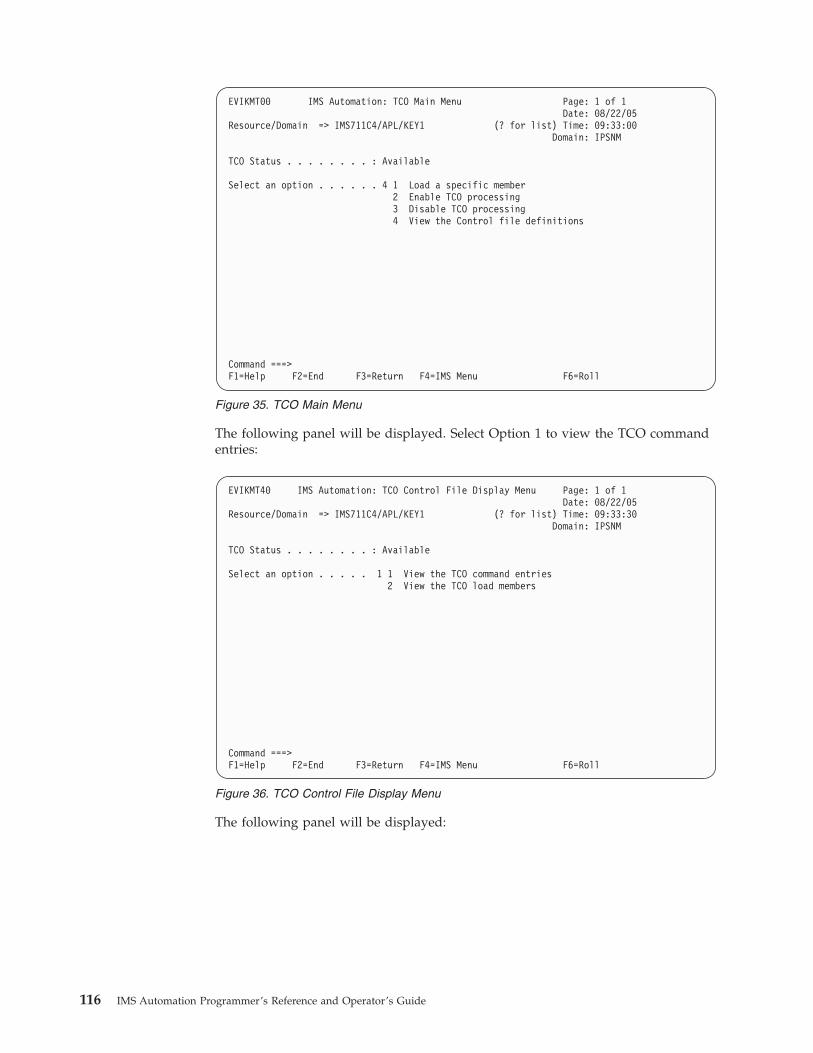
The following panel will be displayed. Select Option 1 to view the TCO command
entries:
The following panel will be displayed:
EVIKMT00 IMS Automation: TCO Main Menu Page: 1 of 1
Date: 08/22/05
Resource/Domain => IMS711C4/APL/KEY1 (? for list) Time: 09:33:00
Domain: IPSNM
TCO Status . . . . . . . . : Available
Select an option . . . . . . 4 1 Load a specific member
2 Enable TCO processing
3 Disable TCO processing
4 View the Control file definitions
Command ===>
F1=Help F2=End F3=Return F4=IMS Menu F6=Roll
Figure 35. TCO Main Menu
EVIKMT40 IMS Automation: TCO Control File Display Menu Page: 1 of 1
Date: 08/22/05
Resource/Domain => IMS711C4/APL/KEY1 (? for list) Time: 09:33:30
Domain: IPSNM
TCO Status . . . . . . . . : Available
Select an option . . . . . 1 1 View the TCO command entries
2 View the TCO load members
Command ===>
F1=Help F2=End F3=Return F4=IMS Menu F6=Roll
Figure 36. TCO Control File Display Menu
116 IMS Automation Programmer’s Reference and Operator’s Guide

Select Option 2 from the TCO Control File Display Menu to view the TCO load
members:
The following panel will be displayed:
AOFK3D0X SA z/OS - Command Response Line 1 of 7
Domain ID = IPSNM ---------- DISPACF ---------- Date = 08/22/05
Operator ID = ABCD Time = 04:51:24
Command = ACF ENTRY=IMS711C4,TYPE=TCO,REQ=DISP
SYSTEM = KEY1 AUTOMATION CONFIGURATION DISPLAY - ENTRY= IMS711C4
-----------------------------------------------------------
AUTOMATION CONFIGURATION DISPLAY - ENTRY= IMS711C4
TYPE IS TCO
REPLY = (INIT,,’DFSTCF LOAD DFSTCF .’)
REPLY = (SPEC,,’DFSTCF LOAD &EHKVAR1 .’)
REPLY = (START,,’/START LTERM DFSTCFI .’)
REPLY = (STOP,,’/PSTOP LTERM DFSTCFI .’)
END OF MULTI-LINE MESSAGE GROUP
Action ===>
PF1= Help PF3= Return PF5= Refresh
PF6= Roll
Figure 37. TCO Configuration Display Panel
EVIKMT40 IMS Automation: TCO Control File Display Menu Page: 1 of 1
Date: 08/22/05
Resource/Domain => IMS711C4/APL/KEY1 (? for list) Time: 09:35:00
Domain: IPSNM
TCO Status . . . . . . . . : Available
Select an option . . . . . 2 1 View the TCO command entries
2 View the TCO load members
Command ===>
F1=Help F2=End F3=Return F4=IMS Menu F6=Roll
Figure 38. TCO Control File Display Menu
Chapter 8. TCO Functions 117

AOFK3D0X SA z/OS - Command Response Line 1 of 6
Domain ID = IPSNM ---------- DISPACF ---------- Date = 08/22/05
Operator ID = SCOT Time = 06:43:41
Command = ACF ENTRY=IMS711C4,TYPE=TCOMEMBERS,REQ=DISP
SYSTEM = KEY1 AUTOMATION CONFIGURATION DISPLAY - ENTRY= IMS631C4
-------------------------------------------------------------------------------
AUTOMATION CONFIGURATION DISPLAY - ENTRY= IMS7311C4
TYPE IS TCOMEMBERS
NAME = (STRTLNES,’START LINES’)
NAME = (ASGNTRAN,’ASSIGN TRANSACTIONS’)
NAME = (DISPROG,’DISPLAY ACTIVE PROGRAMS’)
END OF MULTI-LINE MESSAGE GROUP
Command ===>
PF1=Help PF2=End PF3=Return PF6=Roll
PF9=Refresh PF12=Retrieve
Figure 39. TCO Configuration Display Panel
118 IMS Automation Programmer’s Reference and Operator’s Guide

Chapter 9. Displaying Critical Messages
Through the Critical Message Manager, IMS Automation utilizes the SA z/OS
Status Display Facility (SDF). The Critical Message Manager displays critical
messages in a prioritized, scrollable format. Messages are defined as critical in the
AT.
Select option 7 from the main menu to display Figure 40.
SDF’s IMS Monitor Panel, shown in Figure 40, lists categories of critical messages.
If the CMM has accumulated any critical messages for a category, that category
will be highlighted, according to severity of message.
KEY1I IMS MONITOR PANEL
MSC Links
OLDS
Recons
Transactions
CF Structures
08/22/05 10:38
===>
PF1=HELP 2=DETAIL 3=END 6=ROLL 7=UP 8=DN 12=TOP
Figure 40. Critical Messages Manager Panel. If critical messages have accumulated for a
category, the category will be highlighted.
© Copyright IBM Corp. 1990, 2006 119

In addition to SDF, many IMS messages are captured via Captured Message
support. These can be displayed from the DISPINFO command for the subsystem.
To View Critical Messages
1. Tab to the category you wish to view.
2. Press PF2 to display the detailed list.
Figure 41 shows a sample critical message display.
---- DETAIL STATUS DISPLAY ----
1 OF 6
COMPONENT: DXR008E SYSTEM : SY1
COLOR : YELLOW PRIORITY : 501
DATE : 08/22/05 TIME : 17:07:30
REPORTER : AUTO1 NODE : CNM01
REFERENCE VALUE: IMS10AA-DXR0108E
JOB IMS10AA - DXR008E IRLM INITIALIZATION ABEND
===>
1=HELP 3=RETURN 6=ROLL 7=UP 8=DOWN 9=ASSIST 10=DELETE 11=BOTTOM 12=TOP
Figure 41. Detail Display of Critical Message
120 IMS Automation Programmer’s Reference and Operator’s Guide

Chapter 10. Broadcasting Messages, Issuing Commands, and
Listing Information for an IMS Resource
With the INGIMS command dialog you can issue any IMS operator commands,
broadcast messages to all or selected IMS users, and display information about
IMS resources.
For a detailed description of the INGIMS command, refer to IBM Tivoli System
Automation for z/OS Operator’s Commands.
You can specify the following:
Resource
Specifies the name of an IMS resource. The format is name/type/system or
name/type for sysplex resources. Wildcard characters are supported.
System
Is the name of the system (system name, domain id, or syplex name) to
which the command is issued. This is only necessary when the resource is
not part of the local sysplex.
Request
Specifies the request to be issued to the IMS subsystem. It can be one of
the following: CMD, BROADCAST or INFO.
IMS Command
Specifies the IMS transaction and its parameters to be executed. The IMS
command field is automatically filled with the text above. You can make
changes to it before pressing Enter to execute the transaction.
IMS Route
Specifies the routing information. The routing information format is the
same as specified for the /BRO command.
IMS Message
Specifies the message to be sent to all or selected IMS users or
terminals.For example, you can notify users of a planned shutdown.
EVIKYCMD SA z/OS - Command Dialogs Line
Domain ID = IPSFM ---------- INGIMS ---------- Date = 08/22/05
Operator ID = ASTA Time = 16:41:03
Resource => IMS721C4/APL/KEY2 Format: name/type/system
System => System name, domain ID or sysplex name
Request => BROADCAST CMD, BROADCAST or INFO
IMS Command => BROADCAST
IMS Route => ACTIVE
IMS Message =>
=>
Command ===>
PF1=Help PF2=End PF3=Return PF4=DISPINFO PF6=Roll
PF9=Refresh PF12=Retrieve
Figure 42. INGIMS Command Dialog
© Copyright IBM Corp. 1990, 2006 121

With PF4 DISPINFO, you can display detailed information about the specified
subsystem.
122 IMS Automation Programmer’s Reference and Operator’s Guide

Chapter 11. The Status Display Facility
The Status Display Facility uses color to represent the various subsystem resource
statuses such as error, warning, action, or informational states. Typically, a
subsystem shown in green on a Status Display Facility status panel indicates that it
is up, whereas red indicates a stopped or problem state.
The Status Display Facility status display panels can be tailored to present the
status of system components in a hierarchical manner. The hierarchical display of
status information is implemented using tree structures. A tree structure always
starts with the system name as the root component. The ″leaves″ of the tree are the
monitored resources.
Color can be propagated up or down the leaves of the tree structure based on the
order of dependencies. The effect of propagation is to consolidate, at the root
component, the status of all the monitored resources in that system. In this way,
the color of the root component reflects the most important or critical status in a
computer operations center. If all the monitored resources are green, the root
component (the system) will be green.
IMS Automation provides additional Status Display Facility panels that monitor
events that occur in the following areas for all IMS regions defined to IMS
Automation:
MSC Links
Shows the Status of MSC Links
OLDS Shows the error status of OLDS datasets.
Recons
Shows the error status of RECONS datasets.
Transactions
Shows any transactions that have encountered an error.
CF Structures
Shows coupling facility structures used by IMS that have errors.
To use the IMS Automation Status Display Facility panels, enter SDF on a NetView
panel command line. A panel similar to the following is displayed:
© Copyright IBM Corp. 1990, 2006 123

Note: Sample Status Display Facility panels are provided with IMS Automation.
The system programmer customizes the panels for your specific
environment, so the panels shown here will not look exactly like your
panels.
This could be your primary panel that lists the systems and their status. The color
of KEY1 through KEY4 will reflect the most critical status of any resource in that
system.
If you place the cursor under the letter I on the panel displayed in Figure 43 and
press PF8, the following panel displays (assuming you are using the default
sample panels):
SYSTEM SA z/OS - SUPPORT SYSTEMS
System Subsystems WTORs Gateways Products System
KEY1 IM631C4 NETBTST1 IPSFNO C I D O S C M B T U
KEY2 C I D O S C M B T U
KEY3 C I D O S C M B T U
KEY4 C I D O S C M B T U
XXXX C I D O S C M B T U
08/22/05 10:45
===>
1=HELP 2=DETAIL 3=RETURN 6=ROLL 8=NEXT SCR 10=LEFT 11=RIGHT 12=TOP
Figure 43. Status Display Facility Main Panel
KEY1I IMS MONITOR PANEL
Archive
MSC Links
OLDS
Recons
Transactions
CF Structures
08/22/05 10:38
===>
PF1=HELP 2=DETAIL 3=END 6=ROLL 7=UP 8=DN 12=TOP
Figure 44. IMS Monitor Panel
124 IMS Automation Programmer’s Reference and Operator’s Guide

This shows several categories in which IMS status is important. If the letter I
shown on the previous panel was red, then at least one of the items on the IMS
Monitor panel will be red. Tab down to the red item and press PF8. This displays
the messages logged against that item, as shown in the following panel:
Note: If the full message is not displayed on the screen, press PF11 to shift to the
right.
To see the detail of a message, tab down to that message and press PF2. This
displays a panel similar to the following:
To delete a message, press PF4 on this screen.
KEY1IOL1 IMS OLDS
System Message text
08/22/05 10:59:31 IMS712CX " IMS712CX NEEDS ANOTHER OLDS DATASET - OLDS SHO
08/22/05 10:59
===>
PF1=HELP 2=DETAIL 3=RET 6=ROLL 7=UP 11=RT 12=TOP
Figure 45. IMS Monitor Panel
---- DETAIL STATUS DISPLAY ----
1 OF 1
COMPONENT: IMS712CX SYSTEM : KEY1
COLOR : PINK PRIORITY : 601
DATE : 08/22/05 TIME : 10:59:31
REPORTER : KAT NODE : IPSFM
REFERENCE VALUE: IMS712CX_OL_DFS3260
" IMS712CX NEEDS ANOTHER OLDS DATASET - OLDS SHORTAGE"
===>
1=HELP 3=RETURN 4=DELETE 6=ROLL 7=UP 8=DOWN 9=ASSIST 11=BOTTOM 12=TOP
Figure 46. Detail Status Display
Chapter 11. The Status Display Facility 125

Note: If any of the panels have 1 of X in the upper-right corner of the screen,
where X is a number greater than 1, subsequent panels contain additional
data.
Press PF8 to scroll forward to view the information. Press PF7 to scroll back.
126 IMS Automation Programmer’s Reference and Operator’s Guide

Chapter 12. NMC Display Support
The following messages and events will be displayed on NMC against the
subsystem where they occur.
The alerts will be attached to the subsystem as a minor resource and will have the
following resource names:
Messages plexname.resname/APL/sysname.MSG/message_id
MSC Links plexname.resname/APL/sysname.MSC/linkname
OLDS plexname.resname/APL/sysname.OLDS/DFS3258
plexname.resname/APL/sysname.OLDS/DFS3260
plexname.resname/APL/sysname.OLDS/SWITCHING
plexname.resname/APL/sysname.OLDS/ARCHIVE/ddname
plexname.resname/APL/sysname.OLDS/ERROR/ddname
plexname.resname/APL/sysname.OLDS/SPARES
plexname.resname/APL/sysname.OLDS/MINIMUM
Recons plexname.resname/APL/sysname.RECONS/ddname
plexname.resname/APL/sysname.RECONS/SPARE
plexname.resname/APL/sysname.RECONS/DUAL
Transactions plexname.resname/APL/sysname.TRANS/tranname
CQS plexname.resname/APL/sysname.CQS/structure
© Copyright IBM Corp. 1990, 2006 127

128 IMS Automation Programmer’s Reference and Operator’s Guide

Glossary of IMS Automation Terms
This glossary defines special IMS terms used in
the library and words used with other than their
everyday meaning. In some cases, a definition
may not be the only one applicable to a term, but
it gives the particular sense in which it is used in
the IMS Automation Option library.
abend. Abnormal end of task.
ACB. Access Method Control Block (VTAM and
VSAM).
access method. A technique for moving data between
main storage and input/output devices.
ANSI. American National Standards Institute.
AOST. Automated Operator Station Task.
APAR. Authorized program analysis report.
application program. A program written for or by a
user that applies to the user’s work. In data
communication, a program used to connect and
communicate with stations in a network, enabling users
to perform application-oriented activities.
automation. Computer system control of operation
processes.
authorized program analysis report (APAR). A
request for correction of a problem caused by a defect
in a current unaltered release of a program.
batch. An accumulation of data to be processed.
batch message processing. In IMS/VS, a batch
processing program that accesses online data bases and
message queues.
BMP. Batch Message Processing Region.
CCTL. Coordinator Controller.
central processing complex (CPC). A conglomeration
of several processors and other devices in one or more
physical units. This usually means several processors
running under the control of a single MVS/ESA
operating system. For example, a 3090 model 400
processor complex can run as a four-processor CPC, or
it can be partitioned into the equivalent of two 3090
model 200s, each of which runs as a CPC with its own
operating system.
CICS. Customer Information Control System.
CLIST. Command List.
CMM. Critical Message Manager.
CNM. Communications Network Management.
command. In IMS, an instruction similar in format to
a high-level programming language statement.
command list (CLIST). A list of commands and
statements designed to perform a specific function for
the user. Command lists can be written in REXX or in
NetView Command List Language.
common state handler (CSH). Routine that IMS
Automation calls from the NetView Automation Table
to drive the actions defined in state/action tables.
concurrent. Pertaining to the occurrence of two or
more activities within a given interval of time.
CPC. Central Processing Complex.
critical message manager (CMM). Facility in IMS
Automation which displays critical messages in a
scrollable format and enables operators to access
information relating to the critical messages displayed.
CSA. Common Storage Area.
CSH. Common State Handler.
database. A collection of data fundamental to a
system.
database backout. The function of removing changes
made to user data sets by in-flight transactions.
database recovery. The function of restoring the user
data sets, starting with a backup copy and applying all
changes made to each data set after the backup was
taken.
data security. The protection of data against
unauthorized disclosure, transfer, modifications, or
destruction, whether accidental or intentional.
data set. The major unit of data storage and retrieval,
consisting of a collection of data in one of several
prescribed arrangements and described by control
information to which the system has access.
DBCTL. Data Base Control.
DEDB. Data Entry Data Base.
DLISAS. Data Language Interface Separate Address
Space (IMS Batch).
© Copyright IBM Corp. 1990, 2006 129

domain. In IMS, a set of subsystems on a specific
NetView domain defined by the system programmer in
the control file.
end user. In IMS, anyone using IMS to do a job,
usually by interacting with an application program
(transaction) by means of a terminal.
exception. An abnormal condition such as an I/O
error encountered in processing a data set or a file, or
using any resource.
Fast Path. IMS Automation function which enables the
user to access any IMS Automation interface panel by
entering = and an identifying number.
Fast Path Message Region. In IMS, a region that
executes programs that require good response
characteristics and that have large transaction volumes.
Message processing is grouped for load balancing and
synchronized for database integrity and recovery.
focal point system. In IMS, a system in which
multiple subsystems are interconnected. One subsystem
serves as a focal point of control, and the others are
referred to as intermediate or distributed systems.
HM. Help Message.
HSBID. Hot Standby Identifier.
HSSP. High-Speed Sequential Processing.
initial program load (IPL). The initialization
procedure that causes an operating system to
commence operation.
initialization. Actions performed by IMS to construct
the environment in the IMS region to enable IMS
applications to be run. A process started by SA z/OS
and IMS Automation to construct the environment in
which automation will occur.
installation. A particular computing system, in terms
of the work it does and the people who manage it,
operate it, apply it to problems, service it and use the
work it produces. The task of making a program ready
to do useful work. This task includes generating a
program, initializing it, and applying PTFs to it.
Installation Verification Procedure (INSTALL/IVP).
Procedure distributed with the system that tests the
newly generated system to verify that the basic
facilities are functioning correctly.
INSTALL/IVP. Install/Installation Verification
Procedure.
Integrated Resource Lock Manager (IRLM). In IMS
Automation, this facility is used as a lock manager,
both as a single lock manager and in a data sharing
environment.
intercommunication facilities. A generic term
covering intersystem communication (ISC) and
multiregion operation (MRO).
intersystem communication (ISC). Communication
between separate systems by means of SNA
networking facilities or by means of the
application-to-application facilities of an SNA access
method. ISC links IMS systems, and it may be used for
user application-to-user application communication, or
for transparently executing IMS functions on a remote
IMS system.
IPL. Initial Program Load.
IRC. Interregion communication.
IRLM. Integrated Resource Lock Manager.
ISC. Intersystem Communication.
IVP. Installation Verification Procedure.
keyword. A symbol that identifies a parameter. A part
of a command operand that consists of a specific
character string.
local. In data communication, pertaining to devices
that are attached to a CPC by cables, rather than data
links.
local device. A device, such as a terminal, whose
control unit is directly attached to a computer’s data
channel. No data link is used. Contrast with remote
device.
lock manager. Feature of IMS Automation responsible
for serializing the recovery process in areas where
multiple subsystems can invoke recovery actions.
member. See partitioned data set.
MPP. Message Processing Program.
MSC. Multiple Systems Coupling.
MSDB. Main Storage Data Base.
MTO. Master Terminal Operator.
Multiple Systems Coupling (MSC). An IMS/VS
feature that permits geographically dispersed IMS/VS
systems to communicate with each other.
NCCF. Network Communications Control Facility.
network. An interconnected group of nodes. The
assembly of equipment through which connections are
made between data stations.
network configuration. In SNA, the group of links,
nodes, machine features, devices, and programs that
make up a data processing system, a network, or a
communication system.
130 IMS Automation Programmer’s Reference and Operator’s Guide

Network Communications Control Facility (NCCF).
IBM licensed program consisting of a base for
command processors that can monitor, control, and
improve network operations.
non-XRF (non-XRF IMS). Represent IMS in a
non-XRF configuration.
NPDA. Network Problem Determination
Aid/Application.
OLDS. Online Log Data Set.
online. Pertaining to a user’s ability to interact with a
computer. Pertaining to a user’s access to a computer
via a terminal.
panel. In IMS Automation, the set of information
displayed on a single screen of the user interface.
parameter. (ISO) A variable that is given a constant
value for a specified application and that may denote
the application.
partitioned data set (PDS). A data set in direct access
storage that is divided into partitions, called members,
each of which can contain a program, part of a
program, or data. Synonymous with program library.
PDS. Partitioned Data Set.
PPI. Program-to-program interface.
preprocessor. Routine in IMS Automation that enables
the programmer to define unique GLOBALV names to
store the state value of certain processes.
processor (ISO). In a computer, a functional unit that
interprets and executes instructions.
Program-to-program interface (PPI). A NetView
component used by IMS Automation to enable users to
send or receive data buffers from other programs. It
also allows system and application programs to send
alerts to the NetView hardware monitor.
PTF. Program Temporary Fix.
PUT. Program update tape.
RACF. Resource Access Control Facility.
RDS. Restart Data Set.
RECON. Recovery Control.
recovery routine. A routine entered when an error
occurs during the performance of an associated
operation. It isolates the error, assesses the extent of the
error, and attempts to correct the error and resume
operation.
remote. In data communication, pertaining to devices
that are connected to a data processing system through
a data link.
remote device. A device, such as a terminal, connected
to a data processing system through a data link.
remote system. In IMS intercommunication, a system
that the local IMS system accesses via intersystem
communication or multiregion operation.
Resource Access Control Facility (RACF). A licensed
program that provides for access control by identifying
and verifying users to the system, authorizing access to
DASD data sets, logging detected unauthorized access
attempts, and logging detected accesses to protected
data sets.
RMF. Resource Management Facility.
roll. In IMS Automation, the option to begin/rollover
to another NetView session. This action is assigned to
the PF6 key.
SDF. Status Display Facility. The display facility for
SA z/OS.
security. Prevention of access to or use of data or
programs without authorization.
service. The carrying out of effective problem
determination, diagnosis, and repair on a data
processing system or software product.
single-point-of-control. Feature of IMS Automation
enabling the operator to monitor and control IMS
subsystems from a single NetView console.
SLDS. System Log Data Set.
SMU. Security Maintenance Utility.
SNA. Systems Network Architecture.
software. (ISO) Programs, procedures, rules, and any
associated documentation pertaining to the operation of
a computer system. Contrast with hardware.
startup. The operation of starting up IMS by the
system operator.
state/action table. In IMS Automation, state/action
tables are a matrix of system events, states, and actions
created by the system programmer. When an event
occurs, the system references the state/action table and
takes appropriate action.
status code. In IMS/VS, a two-character code in the
program communication block (PCB) mask that
indicates the results of a DL/1 call.
system. In IMS, an assembly of hardware and
software capable of providing the facilities of IMS for a
particular installation.
system initialization table. A table containing
user-specified data that will control a system
initialization process.
Glossary of IMS Automation Terms 131

systems network architecture (SNA). The description
of the logical structure, formats, protocols, and
operational sequences for transmitting information
units through and controlling the configuration and
operation of networks.
task. (ISO) A basic unit of work to be accomplished by
a computer. Under IMS, the execution of a transaction
for a particular user.
TCO. Timer-Controlled Operations.
terminal. A point in a system or communication
network at which data can either enter or leave. In
IMS, a device, often equipped with a keyboard and
some kind of display, capable of sending and receiving
information over a communication channel.
terminal operator. The user of a terminal.
transaction. A transaction may be regarded as a unit
of processing (consisting of one or more application
programs) initiated by a single request, often from a
terminal. A transaction may require the initiation of one
or more tasks for its execution.
update. To modify a file with current information.
VSCR. Virtual Storage Constraint Relief.
VTAM. Virtual Telecommunications Access Method.
VTAM is one of the ways IMS communicates with
terminals.
WTOR. Write To Operator with Reply.
XRF. Extended recovery facility, a software function
that minimizes the effects of various failures on the end
users.
132 IMS Automation Programmer’s Reference and Operator’s Guide

Index
Special characters*IMS 7
&APPLPARMS 19
AABCODEPROG 26, 34
ABCODES 36
ABCODETRAN 26, 37
abend codes 26
ACORESTART 39
applicationspolicy items
AUTOMATION INFO 18, 21
MESSAGES/USER DATA 24
MINOR RESOURCE FLAGS 23
RESOURCE THRESHOLDS 24,
26
SHUTDOWN 19, 21
STARTUP 18
STATE ACTION TABLE 28
automationoperators 7
BBRO 40
broadcasting messages 121
CCHE 41
CMM (Critical Message Manager) 119
commandsEVIEX002 84
EVIEX003 85
IMSBMSG 88
IMSCMD 90
IMSQRY 91
IMSRCMD 94
INGIMS 95, 121
SDF 123
control regions 9
shutdown 19
startup 18
CQS environmentCQS0031A keyword 42
CQS0032A keyword 43
CQS0033A keyword 44
CQSET keyword 45
CQS regions 10
CQS0031A 42
CQS0032A 43
CQS0033A 44
CQSET 45
Critical Message Manager (CMM) 119
customizationSA z/OS definitions for IMS 7
Ddefining
IMS PPI receiver task 13
NetView PPI receiver task 13
dependenciesFDR environment 17
IMS-specific restrictions 17
dependent regionshutdown 21
startup 18
dependent regions 10
detailed status 103
DFS2142 46
DFS2161I 47
DFS2169I 48
DFS3258A 49
DFS5541A 50
DFS554A 27
DFS690A 52
DFS810A 53
DFS989I 55
DFS994I 57
DFSMDA dynamic allocation macro 61
displayingCritical Message Manager
(CMM) 119
DISPTRG 101
EEVIET00J 21
EVIEX002 84
EVIEX003 85
Ffast path 101
FDR environment 3
recommended relationships 17
FDR regions 10
HHOLDQ 58
IIMS application samples 8
IMS Automation panelsActive Dependent Regions 106
Broadcast 121
Critical Message Manager 119
Defined Dependent Regions 105
IMS Monitor 119
Inquire Subsystem Components 103
search function 100
Subsystem Information 103, 104
TCO Main Menu 111
IMS Message Processing 4
IMS monitor panel 124
IMSBMSG 88
IMSCMD 90
IMSINFO 59
IMSPlex support subsystems 23
IMSQRY 91
IMSRCMD 94
INGIMS 95, 121
INGLIST 108, 110
INGREQ 19, 20, 53, 55, 72, 107
Appl Parms field 108, 109
Type field 107
INGSCHED 101
Llocal applications 29
LookAt message retrieval tool xii
Mmain menu 100
master terminal functionsTCO interface 111
Message ProcessingIMS 4
message retrieval tool, LookAt xii
messagesbroadcasting 121
MESSAGES/USER DATA keywordsABCODEPROG 26, 34
ABCODES 36
ABCODETRAN 26, 37
ACORESTART 39
BRO 40
CHE 41
CQS0031A 42
CQS0032A 43
CQS0033A 44
CQSET 45
DFS2142 46
DFS2161I 47
DFS2169I 48
DFS3258A 49
DFS554A 27
DFS554I 50
DFS690A 52
DFS810A 53
DFS989I 55
DFS994I 57
HOLDQ 58
IMSINFO 59
OLDS 60
POSTCHKP 63
PRECHKP 65
RECONS 67
RELEASEQ 69
RESTARTABORT 70
SHUTTYPES 19, 72
SNAPQ 74
© Copyright IBM Corp. 1990, 2006 133

MESSAGES/USER DATA keywords
(continued)STOPBMPREGION 21, 75
STOPFPREGION 21, 77
STOPREGION 21, 78
TCO 80
TCOMEMBERS 81
minor resourcesdefinitions for component
recovery 23
MSC links 11
NNetView
defining PPI receiver task 13
NMC Display Support 127
OOLDS 11, 60
Ppolicy objects
STATE/ACTION TABLES 28
POSTCHKP 63
PPI (see program-to-program interface) 3
PRECHKP 65
ProcessingIMS Messages 4
program-to-program interface 3
RRECONS 11, 67
recovery 3
abend codes 26
DFS554A 27
minor resources 25
MSC links 23
OLDS 23
programs 23
thresholds 26
transactions 23, 24
RELEASEQ 69
RESTARTABORT 70
SSA z/OS operator commands
DISPTRG 101
INGLIST 108, 110
INGREQ 19, 20, 53, 55, 72, 107
INGSCHED 101
selecting a subsystem 102
shutdowncommands
EVIET001 19
EVIET00J 21
control regions 19
dependent regions 21
options 19, 109
types 19
FORCE 19
shutdown (continued)types (continued)
IMMED 19
NORM 19
SHUTTYPES 72
SNAPQ 74
startupcommands 18
control regions 18
dependent regions 18
types 107
State/Action Table 8
state/action tables 12, 28
default tables 28
status display facility 123
STOPBMPREGION 21, 75
STOPFPREGION 21, 77
STOPREGION 21, 78
subsystemsselecting 102
shutting down 108
starting 107
support subsystemsIMSPlex 23
Ttakeover reason code 103
TCO 80
TCO functions 111
TCOMEMBERS 81
thresholds for recovery 24
Timer-Controlled Operations (TCO)
interface 111
transactionsrecovery 12, 24
Vvariables
&APPLPARMS 19
XXRF environment
IMSINFO keyword 59
takeover reason code 103
134 IMS Automation Programmer’s Reference and Operator’s Guide

Readers’ Comments — We’d Like to Hear from You
System Automation for z/OS
IMS Automation Programmer’s Reference and Operator’s Guide
Version 3 Release 1
Publication No. SC33-8268-02
Overall, how satisfied are you with the information in this book?
Very Satisfied Satisfied Neutral Dissatisfied Very
Dissatisfied
Overall satisfaction h h h h h
How satisfied are you that the information in this book is:
Very Satisfied Satisfied Neutral Dissatisfied Very
Dissatisfied
Accurate h h h h h
Complete h h h h h
Easy to find h h h h h
Easy to understand h h h h h
Well organized h h h h h
Applicable to your tasks h h h h h
Please tell us how we can improve this book:
Thank you for your responses. May we contact you? h Yes h No
When you send comments to IBM, you grant IBM a nonexclusive right to use or distribute your comments in any
way it believes appropriate without incurring any obligation to you. IBM or any other organizations will only use
the personal information that you supply to contact you about the issues that you state on this form.
Name
Address
Company or Organization
Phone No.

Readers’ Comments — We’d Like to Hear from You SC33-8268-02
SC33-8268-02
����
Cut or FoldAlong Line
Cut or FoldAlong Line
Fold and Tape Please do not staple Fold and Tape
Fold and Tape Please do not staple Fold and Tape
NO POSTAGENECESSARYIF MAILED IN THEUNITED STATES
BUSINESS REPLY MAIL FIRST-CLASS MAIL PERMIT NO. 40 ARMONK, NEW YORK
POSTAGE WILL BE PAID BY ADDRESSEE
IBM Deutschland Entwicklung GmbH
Department 3248
Schönaicher Strasse 220
D-71032 Böblingen
Federal Republic of Germany
72031-0000
_ _ _ _ _ _ _ _ _ _ _ _ _ _ _ _ _ _ _ _ _ _ _ _ _ _ _ _ _ _ _ _ _ _ _ _ _ _ _ _ _ _ _ _ _ _ _ _ _ _ _ _ _ _ _ _ _ _ _ _ _ _ _ _ _ _ _ _ _ _ _ _ _ _ _ _ _ _ _ _ _ _ _ _ _ _ _ _ _
_ _ _ _ _ _ _ _ _ _ _ _ _ _ _ _ _ _ _ _ _ _ _ _ _ _ _ _ _ _ _ _ _ _ _ _ _ _ _ _ _ _ _ _ _ _ _ _ _ _ _ _ _ _ _ _ _ _ _ _ _ _ _ _ _ _ _ _ _ _ _ _ _ _ _ _ _ _ _ _ _ _ _ _ _ _ _ _ _
__
__
__
__
__
__
__
__
__
__
__
__
__
__
__
__
__
__
__
__
__
__
__
__
__
__
__
__
__
__
__
__
__
__
__
__
__
__
__
__
__
__
__
__
__
__
__
__
__
_


����
Program Number: 5698-SA3
Printed in USA
SC33-8268-02