imps 4000 - automation solutions rosemount analytical...imps 4000 calibration setup ... if not...
TRANSCRIPT

Instruction ManualIB-106-400IMPS Rev. 1.0October 2000
http://www.processanalytic.com
IMPS 4000Intelligent MultiprobeTest Gas Sequencer

Emerson Process ManagementRosemount Analytical Inc.Process Analytic Division1201 N. Main St.Orrville, OH 44667-0901T (330) 682-9010F (330) 684-4434e-mail: [email protected]://www.processanalytic.com
ESSENTIAL INSTRUCTIONSREAD THIS PAGE BEFORE PROCEEDING!
Rosemount Analytical designs, manufactures and tests its products to meet many national andinternational standards. Because these instruments are sophisticated technical products, youMUST properly install, use, and maintain them to ensure they continue to operate within theirnormal specifications. The following instructions MUST be adhered to and integrated into yoursafety program when installing, using, and maintaining Rosemount Analytical products. Failure tofollow the proper instructions may cause any one of the following situations to occur: Loss of life;personal injury; property damage; damage to this instrument; and warranty invalidation.
• Read all instructions prior to installing, operating, and servicing the product.
• If you do not understand any of the instructions, contact your Rosemount Analytical repre-sentative for clarification.
• Follow all warnings, cautions, and instructions marked on and supplied with the product.
• Inform and educate your personnel in the proper installation, operation, and mainte-nance of the product.
• Install your equipment as specified in the Installation Instructions of the appropriate In-struction Manual and per applicable local and national codes. Connect all products to theproper electrical and pressure sources.
• To ensure proper performance, use qualified personnel to install, operate, update, program,and maintain the product.
• When replacement parts are required, ensure that qualified people use replacement partsspecified by Rosemount. Unauthorized parts and procedures can affect the product�s per-formance, place the safe operation of your process at risk, and VOID YOUR WARRANTY.Look-alike substitutions may result in fire, electrical hazards, or improper operation.
• Ensure that all equipment doors are closed and protective covers are in place, exceptwhen maintenance is being performed by qualified persons, to prevent electrical shockand personal injury.
The information contained in this document is subject to change without notice.

HIGHLIGHTS OF CHANGES
Effective February, 1999 Rev. 1.0
Page Summary
Page 1-1 Added note concerning the Oxymitter 5000.


Instruction Manual106-400IMPS Rev. 1.0
October 2000
Rosemount Analytical Inc. A Division of Emerson Process Management i
IMPS 4000
TABLE OF CONTENTS
PREFACE......................................................................................................................... P1Definitions ......................................................................................................................... P1Safety Instructions ........................................................................................................... P2
1-0 DESCRIPTION AND SPECIFICATIONS........................................................................ 1-11-1 Introduction ...................................................................................................................... 1-11-2 Component Checklist ...................................................................................................... 1-11-3 Physical Description ........................................................................................................ 1-21-4 Specifications................................................................................................................... 1-31-5 Theory Of Operation (Figure. 1-3) ................................................................................... 1-41-6 Z-Purge Option ............................................................................................................... 1-5
2-0 INSTALLATION .............................................................................................................. 2-12-1 Overview.......................................................................................................................... 2-12-2 Mechanical Installation .................................................................................................... 2-12-3 Gas Connections ............................................................................................................. 2-22-4 Electrical Connections .................................................................................................... 2-2
3-0 OPERATION ................................................................................................................... 3-13-1 Overview.......................................................................................................................... 3-13-2 Calibration Requirements ............................................................................................... 3-13-3 Operator Interface Description ...................................................................................... 3-23-4 Using The Operator Interface....................................................................................... 3-43-5 Test Gas Flow Setup ....................................................................................................... 3-43-6 Automatic Calibration ...................................................................................................... 3-53-7 Semi-Automatic Calibration ............................................................................................ 3-5
4-0 MAINTENANCE AND SERVICE .................................................................................... 4-14-1 Overview.......................................................................................................................... 4-14-2 Fuse Replacement ......................................................................................................... 4-14-3 PLC Replacement ........................................................................................................... 4-24-4 Operator Interface Replacement ................................................................................... 4-34-5 Solenoid Replacement ................................................................................................... 4-34-6 Pressure Regulator Maintenance.................................................................................. 4-44-7 Flowmeter Adjustments .................................................................................................. 4-4
5-0 TROUBLESHOOTING.................................................................................................... 5-15-1 Overview.......................................................................................................................... 5-15-2 Troubleshooting............................................................................................................... 5-15-3 Calibration Troubleshooting............................................................................................. 5-35-4 PLC I/O LED Indications.................................................................................................. 5-4
6-0 RETURN OF MATERIAL .............................................................................................. 6-1
7-0 REPLACEMENT PARTS ............................................................................................... 7-1
8-0 INDEX.............................................................................................................................. 8-1

Instruction ManualIB-106-400IMPS Rev. 1.0October 2000
ii Rosemount Analytical Inc. A Division of Emerson Process Management
IMPS 4000
LIST OF ILLUSTRATIONS
Figure 1-1. Typical IMPS 4000 Package..................................................................................... 1-1Figure 1-2. IMPS Components .................................................................................................... 1-3Figure 1-3. IMPS 4000 Calibration Setup.................................................................................... 1-4Figure 1-4. IMPS 4000 with Z-Purge........................................................................................... 1-6Figure 2-1. Mechanical Installation.............................................................................................. 2-1Figure 2-2. Gas Connections....................................................................................................... 2-2Figure 2-3. Electrical Connections............................................................................................... 2-3Figure 3-1. Operator Interface..................................................................................................... 3-2Figure 3-2. Change Presets Display Mode ................................................................................. 3-3Figure 3-3. Message Display Mode............................................................................................. 3-4Figure 4-1. IMPS 4000, Exploded View....................................................................................... 4-0Figure 4-2. PLC Connections ...................................................................................................... 4-2Figure 5-1. IMPS Troubleshooting Flowchart.............................................................................. 5-2Figure 5-2. PLC I/O LEDs............................................................................................................ 5-4
LIST OF TABLES
Table 1-1. IMPS 4000 Versions................................................................................................... 1-1Table 1-2. IMPS 4000 Specifications .......................................................................................... 1-3Table 3-1. Membrane Key Descriptions ...................................................................................... 3-2Table 3-2. Change Presets Display Mode Parameters............................................................... 3-3Table 3-3. Message Display Mode Parameter ............................................................................ 3-4Table 5-1. Fault Finding............................................................................................................... 5-1Table 5-2. Cal Fail Fault Finding ................................................................................................. 5-3Table 5-3. PLC Inputs.................................................................................................................. 5-4Table 5-4. PLC Outputs............................................................................................................... 5-5Table 7-1. Replacement Parts for the IMPS 4000....................................................................... 7-1

Instruction Manual106-400IMPS Rev. 1.0
October 2000
Rosemount Analytical Inc. A Division of Emerson Process Management P-1
IMPS 4000
PREFACEThe purpose of this manual is to provide information concerning the components, func-tions, installation and maintenance of this particular test gas sequencer.Some sections may describe equipment not used in your configuration. The user shouldbecome thoroughly familiar with the operation of this module before operating it. Readthis instruction manual completely.
DEFINITIONSThe following definitions apply to WARNINGS, CAUTIONS, and NOTES found throughout thispublication.
Highlights an operation or maintenanceprocedure, practice, condition, state-ment, etc. If not strictly observed, couldresult in injury, death, or long-termhealth hazards of personnel.
Highlights an operation or maintenanceprocedure, practice, condition, state-ment, etc. If not strictly observed, couldresult in damage to or destruction ofequipment, or loss of effectiveness.
NOTEHighlights an essential operating procedure,condition, or statement.
: EARTH (GROUND) TERMINAL
: PROTECTIVE CONDUCTOR TERMINAL
: RISK OF ELECTRICAL SHOCK
: WARNING: REFER TO INSTRUCTION BULLETIN
NOTE TO USERSThe number in the lower right corner of each illustration in this publication is a manual illus-tration number. It is not a part number, and is not related to the illustration in any technicalmanner.

Instruction ManualIB-106-400IMPS Rev. 1.0October 2000
P-2 Rosemount Analytical Inc. A Division of Emerson Process Management
IMPS 4000
IMPORTANT
SAFETY INSTRUCTIONSFOR THE WIRING AND INSTALLATION
OF THIS APPARATUSThe following safety instructions apply specifically to all EU member states. They shouldbe strictly adhered to in order to assure compliance with the Low Voltage Directive. Non-EU states should also comply with the following unless superseded by local or NationalStandards.
1. Adequate earth connections should be made to all earthing points, internal and external,where provided.
2. After installation or troubleshooting, all safety covers and safety grounds must be replaced.The integrity of all earth terminals must be maintained at all times.
3. Mains supply cords should comply with the requirements of IEC227 or IEC245.
4. All wiring shall be suitable for use in an ambient temperature of greater than 75°C.
5. All cable glands used should be of such internal dimensions as to provide adequate cableanchorage.
6. To ensure safe operation of this equipment, connection to the mains supply should only bemade through a circuit breaker which will disconnect all circuits carrying conductors during afault situation. The circuit breaker may also include a mechanically operated isolating switch.If not, then another means of disconnecting the equipment from the supply must be providedand clearly marked as such. Circuit breakers or switches must comply with a recognizedstandard such as IEC947. All wiring must conform with any local standards.
7. Where equipment or covers are marked with the symbol to the right, hazard-ous voltages are likely to be present beneath. These covers should only beremoved when power is removed from the equipment � and then only bytrained service personnel.
8. Where equipment or covers are marked with the symbol to the right, there is adanger from hot surfaces beneath. These covers should only be removed bytrained service personnel when power is removed from the equipment. Cer-tain surfaces may remain hot to the touch.
9. Where equipment or covers are marked with the symbol to the right, refer tothe Operator Manual for instructions.
10. All graphical symbols used in this product are from one or more of the follow-ing standards: EN61010-1, IEC417, and ISO3864.

Instruction Manual106-400IMPS Rev. 1.0
October 2000
Rosemount Analytical Inc. A Division of Emerson Process Management Description and Specifications 1-1
IMPS 4000
SECTION 1DESCRIPTION AND SPECIFICATIONS
NOTEThe SPS 4000 Single Probe Autocalibration Sequencer operates exactly the same with eitherthe Oxymitter 4000 Oxygen Transmitter or the Oxymitter 5000 Oxygen Transmitter withFOUNDATION fieldbus Communications. Any references to the Oxymitter 4000 throughoutthis instruction bulletin also include the Oxymitter 5000. When referred to an instruction bul-letin for more information, reference IB-106-340 for the Oxymitter 4000 and IB-106-340-FB forthe Oxymitter 5000.
1-1 INTRODUCTIONThe Rosemount IMPS 4000 Intelligent Multi-probe Test Gas Sequencer is used with theOxymitter 4000 Oxygen Transmitter. The IMPS4000 has the intelligence to provide test gas se-quencing of up to four Oxymitters to accommo-date automatic and semi-automatic calibrationroutines. Table 1-1 lists the available IMPS4000 versions.
Table 1-1. IMPS 4000 Versions
PARTNUMBER DESCRIPTION
NUMBER OFOXYMITTERS
3D39695G01 IMPS 1
3D39695G02 IMPS 2
3D39695G03 IMPS 3
3D39695G04 IMPS 4
3D39695G05 IMPS w/115 V Htr 1
3D39695G06 IMPS w/115 V Htr 2
3D39695G07 IMPS w/115 V Htr 3
3D39695G08 IMPS w/115 V Htr 4
3D39695G09 IMPS w/220 V Htr 1
3D39695G10 IMPS w/220 V Htr 2
3D39695G11 IMPS w/220 V Htr 3
3D39695G12 IMPS w/200 V Htr 4
1-2 COMPONENT CHECKLISTA typical IMPS 4000 should contain the itemsshown in Figure 1-1. Record the part number,serial number, and order number for the IMPS4000 on the first page of this manual.
21
1. Instruction Bulletin 2. IMPS 4000
Figure 1-1. Typical IMPS 4000 Package
Instruction ManualIB-106-400IMPS Rev. 1.0October 2000
1-2 Description and Specifications Rosemount Analytical Inc. A Division of Emerson Process Management
IMPS 4000
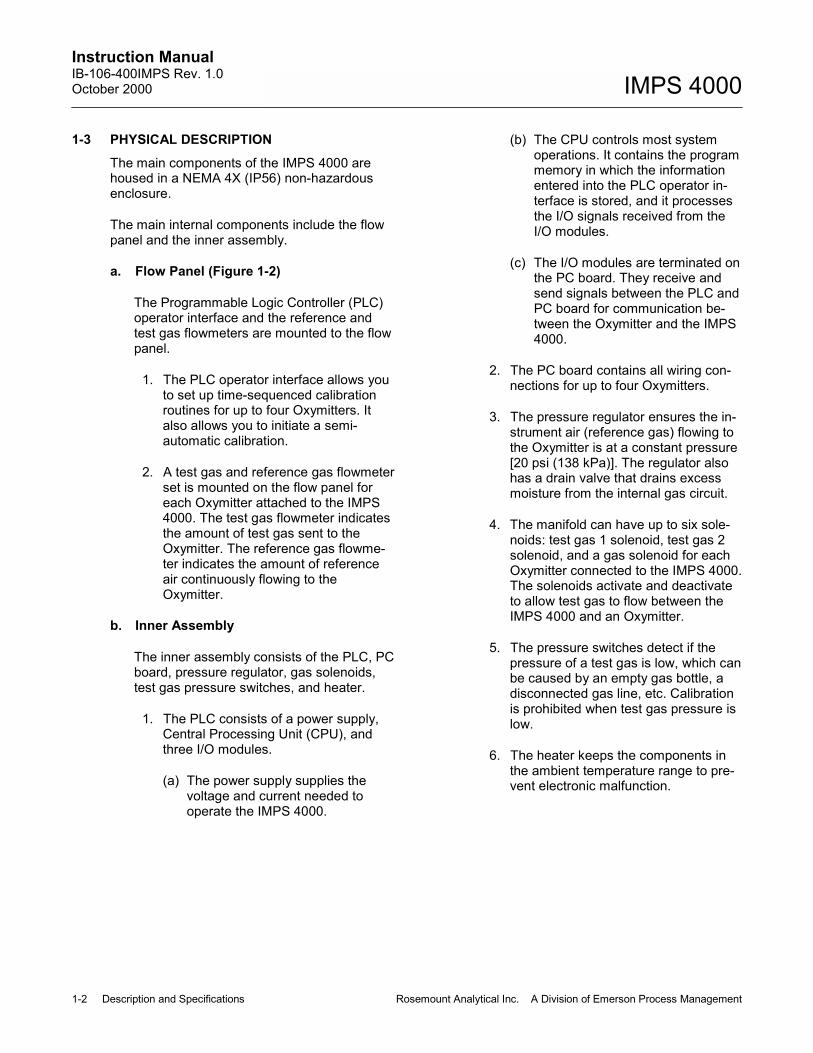
1-3 PHYSICAL DESCRIPTIONThe main components of the IMPS 4000 arehoused in a NEMA 4X (IP56) non-hazardousenclosure.
The main internal components include the flowpanel and the inner assembly.
a. Flow Panel (Figure 1-2)
The Programmable Logic Controller (PLC)operator interface and the reference andtest gas flowmeters are mounted to the flowpanel.
1. The PLC operator interface allows youto set up time-sequenced calibrationroutines for up to four Oxymitters. Italso allows you to initiate a semi-automatic calibration.
2. A test gas and reference gas flowmeterset is mounted on the flow panel foreach Oxymitter attached to the IMPS4000. The test gas flowmeter indicatesthe amount of test gas sent to theOxymitter. The reference gas flowme-ter indicates the amount of referenceair continuously flowing to theOxymitter.
b. Inner Assembly
The inner assembly consists of the PLC, PCboard, pressure regulator, gas solenoids,test gas pressure switches, and heater.
1. The PLC consists of a power supply,Central Processing Unit (CPU), andthree I/O modules.
(a) The power supply supplies thevoltage and current needed tooperate the IMPS 4000.
(b) The CPU controls most systemoperations. It contains the programmemory in which the informationentered into the PLC operator in-terface is stored, and it processesthe I/O signals received from theI/O modules.
(c) The I/O modules are terminated onthe PC board. They receive andsend signals between the PLC andPC board for communication be-tween the Oxymitter and the IMPS4000.
2. The PC board contains all wiring con-nections for up to four Oxymitters.
3. The pressure regulator ensures the in-strument air (reference gas) flowing tothe Oxymitter is at a constant pressure[20 psi (138 kPa)]. The regulator alsohas a drain valve that drains excessmoisture from the internal gas circuit.
4. The manifold can have up to six sole-noids: test gas 1 solenoid, test gas 2solenoid, and a gas solenoid for eachOxymitter connected to the IMPS 4000.The solenoids activate and deactivateto allow test gas to flow between theIMPS 4000 and an Oxymitter.
5. The pressure switches detect if thepressure of a test gas is low, which canbe caused by an empty gas bottle, adisconnected gas line, etc. Calibrationis prohibited when test gas pressure islow.
6. The heater keeps the components inthe ambient temperature range to pre-vent electronic malfunction.
Instruction Manual106-400IMPS Rev. 1.0
October 2000
Rosemount Analytical Inc. A Division of Emerson Process Management Description and Specifications 1-3
IMPS 4000
30
25
20
0
5
10
15
TEST
LO GAS ON
NL
GAS LOW
GAS LOW
HI GAS ON
TR#4 CAL FAIL
TR#3 CAL FAIL
TR#2 CAL FAIL
TR#1 CAL FAIL
J18,19
J21,22
TR#3 INCAL
TR#4 INCAL
TR#1 INCAL
TR#2 INCAL
COMMON
4+
4-
4-
COMMON
3+
3-
2+
2-
1+
1-
J15,16
J12,13TR#
3-
4+
2-
3+
RC#
1+
1-
2+
RELAY
DL240CPU
+
-
LOGICDirect
0.2A24VDC OUT
G
50/60Hz85-264VAC
205CPU
BATT
PWR
OUT
5mA-1.5A5-30VDC
1.5A 50/60Hz
5-240VAC
D2-12TR
8mA
7
6
7
6
5
4
CA
5
4
CBNC
PORT2
PORT1
3
2
1
0
CH4
CH3
CH2
CH1
3
1
2
0
D2-16ND3-220-28VDC
CPU
RUN
TERM
RUN
CPU
RUN
2
3
1
0
B
A
VDC
24
5
4
1.5A 50/60Hz
3
2
1
0
5
4
CB
3
2
1
0
5
4
CA
CB
4
5
0
1
2
3
CA
4
5
5-30VDC5mA-1.5A
0
2
1
3
RELAY
3
2
1
0
B
A
5
4 0
3
2
5-240VAC
D2-12TR
A
B
1
OUT
4
5
30
25
20
0
5
10
15
REF GAS
2.02.0 994994
4.71010 4.710 4.710 4.7
994994 2.02.0
PRESSURE
REF AIR
4321PROBE
TEST GAS
DirectVIEW1000
- +
Rosemount Analytical Inc.
P.O. Box 901, Orrville, Ohio 44667 U.S.A.
50/60HZ
FUSE
3535B07H05
REFERENCE GASFLOWMETERS
TEST GASFLOWMETERS
FLOW PANEL
I/O MODULESCPUPOWER SUPPLY
INNER ASSEMBLY
PLC
PCBOARD
GASSOLENOID(1 OF 4)
MANIFOLDTEST GAS 1
SOLENOIDTEST GAS 2
SOLENOID
TEST GASPRESSURESWITCHES
PRESSUREREGULATOR
OPERATORINTERFACE
Figure 1-2. IMPS Components
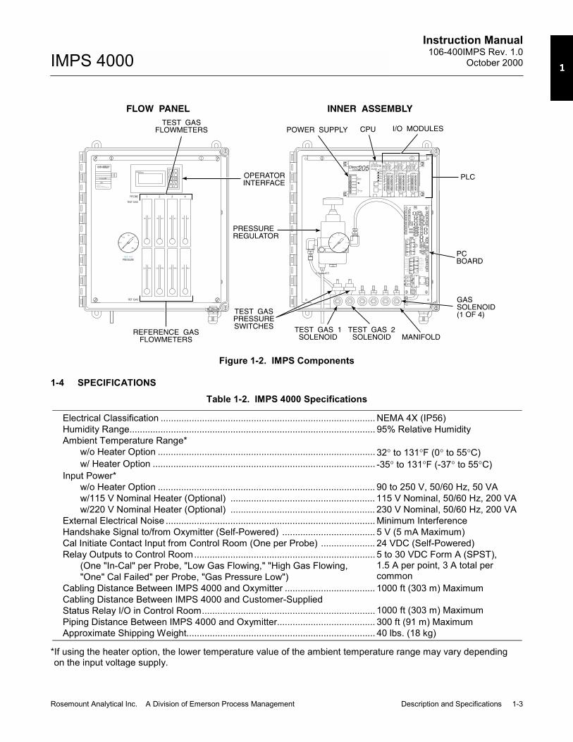
1-4 SPECIFICATIONSTable 1-2. IMPS 4000 Specifications
Electrical Classification ................................................................................... NEMA 4X (IP56)Humidity Range............................................................................................... 95% Relative HumidityAmbient Temperature Range*
w/o Heater Option .................................................................................... 32° to 131°F (0° to 55°C)w/ Heater Option ...................................................................................... -35° to 131°F (-37° to 55°C)
Input Power*w/o Heater Option .................................................................................... 90 to 250 V, 50/60 Hz, 50 VAw/115 V Nominal Heater (Optional) ........................................................ 115 V Nominal, 50/60 Hz, 200 VAw/220 V Nominal Heater (Optional) ........................................................ 230 V Nominal, 50/60 Hz, 200 VA
External Electrical Noise ................................................................................. Minimum InterferenceHandshake Signal to/from Oxymitter (Self-Powered) .................................... 5 V (5 mA Maximum)Cal Initiate Contact Input from Control Room (One per Probe) ..................... 24 VDC (Self-Powered)Relay Outputs to Control Room......................................................................
(One "In-Cal" per Probe, "Low Gas Flowing," "High Gas Flowing,"One" Cal Failed" per Probe, "Gas Pressure Low")
5 to 30 VDC Form A (SPST),1.5 A per point, 3 A total percommon
Cabling Distance Between IMPS 4000 and Oxymitter ................................... 1000 ft (303 m) MaximumCabling Distance Between IMPS 4000 and Customer-SuppliedStatus Relay I/O in Control Room................................................................... 1000 ft (303 m) MaximumPiping Distance Between IMPS 4000 and Oxymitter...................................... 300 ft (91 m) MaximumApproximate Shipping Weight......................................................................... 40 lbs. (18 kg)
*If using the heater option, the lower temperature value of the ambient temperature range may vary dependingon the input voltage supply.

Instruction ManualIB-106-400IMPS Rev. 1.0October 2000
1-4 Description and Specifications Rosemount Analytical Inc. A Division of Emerson Process Management
IMPS 4000
1-5 THEORY OF OPERATION (Figure 1-3)When a calibration is initiated, via the IMPS,HART/AMS, Oxymitter, or remote location, thesignal is sent to the IMPS 4000 PLC. The PLCfirst energizes the Oxymitter solenoid and thenenergizes the test gas 1 (high gas) solenoid.
Test gas 1 flows through the IMPS 4000 to theOxymitter. The Oxymitter measures the oxygencontent of test gas 1 and sends a signal to theIMPS 4000 indicating that it received test gas 1.When the IMPS 4000 receives the signal, thePLC deenergizes the test gas 1 solenoid.
INSTRUMENT AIR IN TEST GAS 1(HIGH O )2
TEST GAS 2(LOW O )2
IMPS 4000
TEST GAS
OXYMITTER LOGIC I/O
OXYMITTER (BOTTOM VIEW)
CALIBRATIONGAS FITTING
REFERENCE AIR
NOTE: A CHECK VALVE IS REQUIREDAT THE OXYMITTER (BETWEENTHE CALIBRATION GAS FITTINGAND THE GAS LINE) TO PREVENTTHE MIGRATION OF PROCESSGASES DOWN THE CALIBRATIONGAS LINE.
CHECK VALVE(SEE NOTE)
Figure 1-3. IMPS 4000 Calibration Setup

Instruction Manual106-400IMPS Rev. 1.0
October 2000
Rosemount Analytical Inc. A Division of Emerson Process Management Description and Specifications 1-5
IMPS 4000
After a time delay that allows test gas 1 to clearthe system, the PLC energizes the test gas 2(low gas) solenoid. Test gas 2 flows through theIMPS 4000 to the Oxymitter. The Oxymittermeasures the oxygen content of test gas 2 andsends a signal to the IMPS 4000 indicating thatit received test gas 2. After measuring the twotest gases, the Oxymitter automatically makesthe internal calibration adjustment and sendsthe signal to the IMPS 4000. When the IMPSreceives the signal, the PLC deenergizes thetest gas 2 solenoid and the Oxymitter solenoid.Whether or not the calibration passes or failsdisplays on the PLC operator interface.
1-6 Z-PURGE OPTIONSome IMPS applications have area safety re-quirements (Class 1, Division 2). These re-quirements may be satisfied with the installationof an optional Z-purge. The Z-Purge providespositive pressure within the IMPS 4000 enclo-sure to keep out dust and other foreign matter.Figure 1-4 shows the Z-purge unit and how itconnects to the IMPS 4000.

Instruction ManualIB-106-400IMPS Rev. 1.0October 2000
1-6 Description and Specifications Rosemount Analytical Inc. A Division of Emerson Process Management
IMPS 4000
WARNING NOTICE
SYSTEM16
(SEE DETAIL "A")
WIRING INLET
1/2" CONDUIT
PRESSURE
SWITCH
ATMOSPHERIC
REF VENT
DIFFERENTIAL
PRESSURE TO
REFERENCE
0-125 PA
INDICATOR
PRESSURE
ENCLOSURE
2 3
ALARM SWITCH (USED ON G02 ONLY)
PRESSURE LOSS
CONTROL VALVE
PRESSURE
REDUNDANT
REGULATOR
SYSTEM
EXPLOSION PROOF
SCREW
CALIBRATION
ORIFICE
VENTURI
ENCLOSURE PURGE LINE
1
2
SUPPLY
BEBCO MODEL Z-PURGE
2.50(63,50)
REFERENCE PURGE
3.00(76,20)
0.437 (11,10) THRU HOLE 2 PLS.
1.50(38,1)
REFERENCE LINE
HOLE PLACEMENT
REAR VIEW
AND
LEFT SIDE VIEW
LABEL ORIENTATION
5
0.75(19,05)
1
1.00(25,40)
1.00(25,40)
(2) PLCS
5
4
3
5 PSIG (34.48 KPa) MAXIMUM.CSA, FM & UL LISTED
CLASS 1, DIV. 1 & 2 GR. C & D
1/4 HP 250 VAC
1/8 HP 125 VAC
15A - 125, 250, 480 VAC
SWITCH CONTACT RATING:
ALARM SWITCHING
ALARM COMMON
ALARM NORMALLY OPEN
ALARM NORMALLY CLOSED
DETAIL "A"
NOCOM NC
WITH A TAMPER-PROOF REGULATOR SET TO
COMPRESSED AIR SUPPLY MUST BE EQUIPPED
6 CUSTOMER SUPPLIED INSTRUMENT QUALITY
AT DISTANCE SHOWN.
CENTER LABELS UNDER FITTING HOLES
5 USE KROY LABEL, BLACK ON CLEAR, 14 PT.
4 TO BE CALLED OUT ON SHOP ORDER.
TO BE INSTALLED ON MPS UNIT
SUPPLIED WITH BEBCO UNIT AND
3 "BEBCO" PURGE WARNING NOTICE
INDICATED ON REFERENCE GAUGE.
SET AIR REGULATOR TO 0.25 INCHES (65PA) AS
2 WITH ELECTRONICS DOOR CLOSED TIGHTLY,
1 CUSTOMER SUPPLIED 0.25" (6.35) O.D. LINE.
NOTES:
1
AS SHOWN.
) 1/4" BULKHEAD CONNECTOR S.S.
) W/ PRESSURE LOSS SWITCH
) W/O PRESSURE LOSS SWITCH
SIZE - REFERENCE INFORMATION
PARTS LIST UNITS: INCHES
DYNASEAL
TUBE FITTING
Z-PURGE UNIT
Z-PURGE UNIT
IMPS ASSEMBLY
PART NAME
PARTS LIST
5
4
3
NOTE
2
1
ITEM
4
DEFINER
)AML
DWG
AML
AML
DWG ) A/R
G02
171801-009
3534B45H03
1A98474H02
PART NUMBEROR REF DWG
22
2 2
1
A/R
1
G01
GROUP
GROUP NOTE
1A98474H01
3D39695GXX
MATL CODE
NOTE: DIMENSIONS IN INCHES WITHMILLIMETERS IN PARENTHESES.
Figure 1-4. IMPS 4000 with Z-Purge
Instruction Manual106-400IMPS Rev. 1.0
October 2000
Rosemount Analytical Inc. A Division of Emerson Process Management Installation 2-1
IMPS 4000
SECTION 2INSTALLATION
2-1 OVERVIEWThis section describes the installation of theIMPS 4000.
Before starting to install this equip-ment, read the �Safety Instructions forthe Wiring and Installation of this Ap-paratus� at the front of this InstructionBulletin. Failure to follow the safetyinstructions could result in injury ordeath.
Install all protective equipment coversand safety ground leads after installa-tion. Failure to install covers andground leads could result in seriousinjury or death.
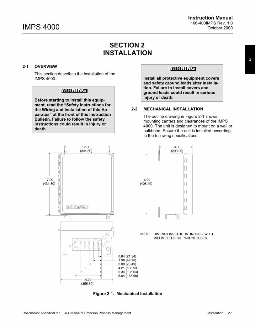
2-2 MECHANICAL INSTALLATIONThe outline drawing in Figure 2-1 showsmounting centers and clearances of the IMPS4000. The unit is designed to mount on a wall orbulkhead. Ensure the unit is installed accordingto the following specifications:
PROBE 1
INSTR
AIR
PROBE 2 PROBE 3 PROBE 4
REF AIR
OUT
OUT
TEST GAS
OUT
REF AIR
OUT
REF AIR
OUT
REF AIR
TEST GAS
OUT
TEST GAS
OUT
TEST GAS
OUT
LOW CAL
GAS INGAS IN
HIGH CAL
0.84 (21,34)1.96 (49,78)3.09 (78,49)4.21 (106,935.34 (135,64)6.64 (168,66)
14.00(355,60)
16.00(406,40)
17.00(431,80)
12.00(304,80)
8.00(203,20)
NOTE: DIMENSIONS ARE IN INCHES WITHMILLIMETERS IN PARENTHESES.
Figure 2-1. Mechanical Installation

Instruction ManualIB-106-400IMPS Rev. 1.0October 2000
2-2 Installation Rosemount Analytical Inc. A Division of Emerson Process Management
IMPS 4000
a. Install the module no further than 300 ft(91 m) from the probe and no further than1000 ft (303 m) from a remote connection orfrom the status relay indicators.
b. Locate units without the optional heaterwhere the ambient temperature is between32° and 131°F (0° and 55°C). For units withthe optional heater, install where the ambi-ent temperature is between -35° and 131°F(-37° and 55°C).
2-3 GAS CONNECTIONSGas connections are located on the bottom ofthe IMPS 4000 and are 1/8-27 NPT fittings (Fig-ure 2-2). Use the following procedure to connectthe test gases:
a. Connect the reference air supply to INSTRAIR. The pressure regulator valve is set atthe factory to 20 psi (138 kPa). If necessary,readjust by turning the knob on the top ofthe valve until the desired pressure isobtained.
b. Connect the O2 test gas 1 to HIGH CALGAS IN. The test gas pressure should beset at 20 psi (138 kPa).
Do not use 100% nitrogen as a low gas(zero gas). It is suggested that gas forthe low (zero) be between 0.4% and2.0% O2. Do not use gases with hydro-carbon concentrations of more than 40parts per million. Failure to use propergases will result in erroneous read-ings.
c. Connect the O2 test gas 1 to LOW CALGAS IN. The test gas pressure should beset at 20 psi (138 kPa).
d. Connect the Oxymitter REF GAS to REFAIR OUT.
e. Connect the Oxymitter CAL GAS to TESTGAS OUT.
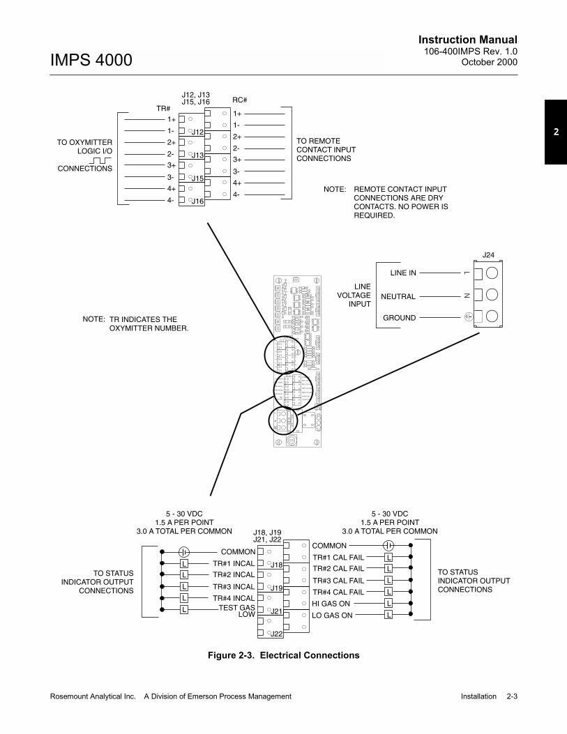
2-4 ELECTRICAL CONNECTIONSAll wiring must conform to local and nationalcodes. Refer to Figure 2-3 and use the followingprocedure to connect the first Oxymitter. Repeatthe procedure for each remaining Oxymitter.
PROBE 1
INSTR
AIRPROBE 2 PROBE 3 PROBE 4
REF AIR
OUT
OUT
TEST GAS
OUT
REF AIR
OUT
REF AIR
OUT
REF AIR
TEST GAS
OUT
TEST GAS
OUT
TEST GASOUT
LOW CAL
GAS INGAS IN
HIGH CAL
NOTE: DIMENSIONS ARE ININCHES WITH MILLIMETERSIN PARENTHESES.
DRAIN
THRU HOLE
0.44 (11,18)
LINE IN
THRU HOLE
0.875 (22,23)
SIGNAL IN
THRU HOLES(4 PLCS)
0.875 (22,23)
1/8-27 NPT(11 PLCS)
Figure 2-2. Gas Connections
Instruction Manual106-400IMPS Rev. 1.0
October 2000
Rosemount Analytical Inc. A Division of Emerson Process Management Installation 2-3
IMPS 4000
NL
TEST
LO GAS ON
NL
GAS LOW
HI GAS ON
TR#4 CAL FAIL
TR#3 CAL FAIL
TR#2 CAL FAIL
TR#1 CAL FAIL
J18,19
J21,22
TR#3 INCAL
TR#4 INCAL
TR#1 INCAL
TR#2 INCAL
COMMON
4+
4-
4-
COMMON
3+
3-
2+
2-
1+
1-
J15,16
J12,13TR#
3-
4+
2-
3+
RC#
1+
1-
2+
COMMONCOMMON
TR#1 CAL FAILTR#1 INCAL
TR#2 CAL FAILTR#2 INCAL
TR#3 CAL FAILTR#3 INCAL
TR#4 CAL FAILTR#4 INCAL
LO GAS ON
HI GAS ONTEST GAS
LOW
J18, J19J21, J22
J12, J13J15, J16
J18
J19
J21
J22
L
L
L
L
L
L
5 - 30 VDC1.5 A PER POINT
3.0 A TOTAL PER COMMON
5 - 30 VDC1.5 A PER POINT
3.0 A TOTAL PER COMMON
TO STATUSINDICATOR OUTPUTCONNECTIONS
TO STATUSINDICATOR OUTPUT
CONNECTIONS
L
L
L
L
L
LINE IN
NEUTRAL
GROUND
LINEVOLTAGE
INPUT
1+1+
1-1-
2+2+
2-2-
3+3+
3-3-
4+4+
4-4-
TO REMOTECONTACT INPUTCONNECTIONS
RC#TR#
J12
J13
J15
J16
TO OXYMITTERLOGIC I/O
CONNECTIONS
NOTE: TR INDICATES THEOXYMITTER NUMBER.
J24
NOTE: REMOTE CONTACT INPUTCONNECTIONS ARE DRYCONTACTS. NO POWER ISREQUIRED.
Figure 2-3. Electrical Connections
Instruction ManualIB-106-400IMPS Rev. 1.0October 2000
2-4 Installation Rosemount Analytical Inc. A Division of Emerson Process Management
IMPS 4000
a. Run the line voltage through the bulkheadfitting on the bottom of the IMPS 4000marked LINE IN. Connect the line voltage tothe J24 terminal. The power supply auto-matically adjusts to the input voltage.Tighten the cord grips to provide strainrelief.
b. Run the handshake logic I/O wires for eachOxymitter through a bulkhead fitting on thebottom of the IMPS 4000 marked SIGNALIN. Dedicate one fitting for each Oxymitter.Connect the Oxymitter logic I/O wires asshown in Figure 2-3.
c. To set up the IMPS 4000 to initiate a cali-bration from a remote location, run the
remote contact input wires through theSIGNAL IN bulkhead fitting. Connect theremote contact input wires as shown inFigure 2-3.
d. Status relay connections are available onthe IMPS 4000 PC board to signal when theOxymitter is in or out of calibration and toindicate calibration gas status. Status relayscan be connected to either indicator lightsor a computer interface. Relay contacts arecapable of handling up to 5 to 30 V, 1.5 Aper point, 3.0 A total per common maximumpower source. Cabling requirement is1000 ft (303 m) maximum. Make the statusrelay switch connections as shown in Figure2-3.

Instruction Manual106-400IMPS Rev. 1.0
October 2000
Rosemount Analytical Inc. A Division of Emerson Process Management Operation 3-1
IMPS 4000
SECTION 3OPERATION
3-1 OVERVIEWThis section specifies the requirements to set upan Oxymitter calibration. It describes the PLCoperator interface and explains how to set uptime-sequenced calibration routines for up tofour Oxymitters using the IMPS 4000. This sec-tion also explains the differences betweenautomatic and semi-automatic calibrations andhow to initiate them.
3-2 CALIBRATION REQUIREMENTSa. Two tanks of precision calibration gas mix-
tures are required. Recommended calibra-tion gases are nominally 0.4% and 8.0%oxygen in nitrogen.
Do not use 100% nitrogen as a low gas(zero gas). It is suggested that gas forthe low (zero) be between 0.4% and2.0% O2. Do not use gases with hydro-carbon concentrations of more than 40parts per million. Failure to use propergases will result in erroneous read-ings.
Two sources of calibrated gas mixtures are:
LIQUID CARBONIC GAS CORP.SPECIALTY GAS LABORATORIES
700 South Alameda StreetLos Angeles, California 90058213/585-2154
767 Industrial RoadSan Carlos, California 94070415/592-7303
9950 Chemical RoadPasadena, Texas 77507713/474-4141
12054 S.W. Doty AvenueChicago, Illinois 60628312/568-8840
603 Bergen StreetHarrison, New Jersey 07029201/485-1995
255 Brimley RoadScarborough, Ontario, Canada416/266-3161
SCOTT ENVIRONMENTALTECHNOLOGY, INC.SCOTT SPECIALTY GASES
2600 Cajon Blvd.San Bernardino, California 92411714/887-2571TWX: 910-390-1159
1290 Combermere StreetTroy, Michigan 48084314/589-2950
Route 611Plumsteadville, Pennsylvania 18949215/766-8861TWX: 510-665-9344
2616 South Loop WestSuite 100Houston, Texas 77054713/669-0469
b. A check valve is required at the Oxymitter(between the calibration fitting and the gasline) to prevent the migration of processgases down the calibration gas line.
A typical calibration setup is shown inFigure 1-3.
Instruction ManualIB-106-400IMPS Rev. 1.0October 2000
3-2 Operation Rosemount Analytical Inc. A Division of Emerson Process Management
IMPS 4000
CLR
-
STAT
<—
PRECHG
+
ENT
OPT
—>
MSG
MEMBRANEKEY PAD
NOTE: THE LCD DISPLAY IN THIS ILLUSTRATION SHOWSTHE MESSAGE DISPLAY MODE. THE CHANGEPRESETS DISPLAY MODE IS SHOWN IN FIGURE 3-2.
LCD DISPLAY
Figure 3-1. Operator Interface
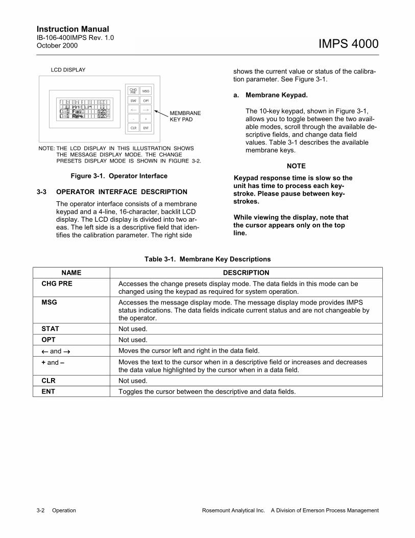
3-3 OPERATOR INTERFACE DESCRIPTIONThe operator interface consists of a membranekeypad and a 4-line, 16-character, backlit LCDdisplay. The LCD display is divided into two ar-eas. The left side is a descriptive field that iden-tifies the calibration parameter. The right side
shows the current value or status of the calibra-tion parameter. See Figure 3-1.
a. Membrane Keypad.
The 10-key keypad, shown in Figure 3-1,allows you to toggle between the two avail-able modes, scroll through the available de-scriptive fields, and change data fieldvalues. Table 3-1 describes the availablemembrane keys.
NOTEKeypad response time is slow so theunit has time to process each key-stroke. Please pause between key-strokes.
While viewing the display, note thatthe cursor appears only on the topline.
Table 3-1. Membrane Key Descriptions
NAME DESCRIPTIONCHG PRE Accesses the change presets display mode. The data fields in this mode can be
changed using the keypad as required for system operation.MSG Accesses the message display mode. The message display mode provides IMPS
status indications. The data fields indicate current status and are not changeable bythe operator.
STAT Not used.OPT Not used.←←←← and →→→→ Moves the cursor left and right in the data field.
+ and � Moves the text to the cursor when in a descriptive field or increases and decreasesthe data value highlighted by the cursor when in a data field.
CLR Not used.ENT Toggles the cursor between the descriptive and data fields.
Instruction Manual106-400IMPS Rev. 1.0
October 2000
Rosemount Analytical Inc. A Division of Emerson Process Management Operation 3-3
IMPS 4000
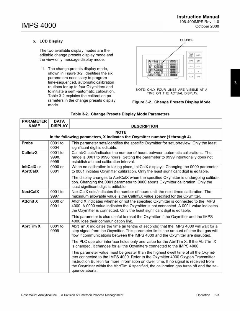
b. LCD Display
The two available display modes are theeditable change presets display mode andthe view-only message display mode.
1. The change presets display mode,shown in Figure 3-2, identifies the sixparameters necessary to programtime-sequenced, automatic calibrationroutines for up to four Oxymitters andto initiate a semi-automatic calibration.Table 3-2 explains the calibration pa-rameters in the change presets displaymode.
MSG
OPT
—>
+
ENTCLR
-
<—
STAT
PRECHG
CURSOR
NOTE: ONLY FOUR LINES ARE VISIBLE AT ATIME ON THE ACTUAL DISPLAY.
Figure 3-2. Change Presets Display Mode
Table 3-2. Change Presets Display Mode Parameters
PARAMETERNAME
DATADISPLAY DESCRIPTION
NOTEIn the following parameters, X indicates the Oxymitter number (1 through 4).
Probe 0001 to0004
This parameter sets/identifies the specific Oxymitter for setup/review. Only the leastsignificant digit is editable.
CalIntvX 0001 to9998,9999
CalIntvX sets/indicates the number of hours between automatic calibrations. Therange is 0001 to 9998 hours. Setting the parameter to 9999 intentionally does notestablish a timed calibration interval.
InitCalX orAbrtCalX
0000 or0001
When no calibration is taking place, InitCalX displays. Changing the 0000 parameterto 0001 initiates Oxymitter calibration. Only the least significant digit is editable.The display changes to AbrtCalX when the specified Oxymitter is undergoing calibra-tion. Changing the 0001 parameter to 0000 aborts Oxymitter calibration. Only theleast significant digit is editable.
NextCalX 0001 to9997
NextCalX sets/indicates the number of hours until the next timed calibration. Themaximum allowable value is the CalIntvX value specified for the Oxymitter.
Attchd X 0000 or0001
Attchd X indicates whether or not the specified Oxymitter is connected to the IMPS4000. A 0000 value indicates the Oxymitter is not connected. A 0001 value indicatesthe Oxymitter is connected. Only the least significant digit is editable.This parameter is also useful to reset the Oxymitter if the Oxymitter and the IMPS4000 lose their communication link.
AbrtTim X 0001 to9999
AbrtTim X indicates the time (in tenths of seconds) that the IMPS 4000 will wait for astep signal from the Oxymitter. This parameter limits the amount of time that gas willflow if communications between the IMPS 4000 and the Oxymitter are disrupted.The PLC operator interface holds only one value for the AbrtTim X. If the AbrtTim Xis changed, it changes for all the Oxymitters connected to the IMPS 4000.This parameter value must be greater than the highest dwell time of all the Oxymit-ters connected to the IMPS 4000. Refer to the Oxymitter 4000 Oxygen TransmitterInstruction Bulletin for more information on dwell time. If no signal is received fromthe Oxymitter within the AbrtTim X specified, the calibration gas turns off and the se-quence aborts.

Instruction ManualIB-106-400IMPS Rev. 1.0October 2000
3-4 Operation Rosemount Analytical Inc. A Division of Emerson Process Management
IMPS 4000
CLR
-
STAT
<—
PRE
CHG
+
ENT
OPT
—>
MSG
Figure 3-3. Message Display Mode
2. The message display mode, shown inFigure 3-3, only indicates IMPS 4000status and is not changeable by theuser. Table 3-3 explains the calibrationstatuses in this mode.
3-4 USING THE OPERATOR INTERFACEa. Selecting a Parameter
The cursor only appears on the top line ofthe change presets display mode. To ac-cess a parameter, scroll the parameter tothe top line of the display. Pressing the+ key scrolls down the list. Pressing the� key scrolls up the list. The list of parame-ters will continuously scroll in either direc-tion when at the top or bottom of thedisplay.
NOTEThe PLC operator interface only usesthe change presets display mode andthe message display mode. If a screendisplays that you do not recognize,press the CHG PRE or MSG key to exitthe unfamiliar screen.
b. Changing a Typical Parameter
Once the parameter you want to change isat the top line, use the ENT key to move thecursor from the descriptive field to the datafield. In the data field, use the ← or → keyto move the cursor left or right in the datafield. Next use the + or � key to increase ordecrease the data value highlighted by thecursor.
3-5 TEST GAS FLOW SETUPAfter setting up the parameters in Table 3-2,calibrate each Oxymitter to verify IMPS 4000operation and the communication link betweenthe sequencer and the Oxymitter.
a. Verify that both test gases are connected tothe IMPS 4000 and the operator interfaceGas Presur parameter in the message dis-play mode indicates OK. Also verify that thepressure regulators on both test gas bottlesare set to 20 psig (138 kPag).
Table 3-3. Message Display Mode Parameter
PARAMETERNAME
DATADISPLAY DESCRIPTION
Prb in Cal none, 1,2, 3, or 4
Prb in Cal indicates the Oxymitter currently undergoing calibration. If no Oxymitter isbeing calibrated, the parameter displays none.
Gas Presur OK orLOW
Gas Presur indicates if the calibration gas pressure is high enough for calibration. OKindicates the pressure is high enough. LOW indicates the calibration gas pressure istoo low and calibration will not occur.
Cal Fail none, 1,2, 3, or 4
If an Oxymitter fails calibration, Cal Fail displays the Oxymitter number. If the Oxy-mitter does not fail calibration, Cal Fail displays none.
Cal Reqd none or1, 2, 3,and/or 4
Cal Reqd displays the Oxymitter(s) waiting to be calibrated when another Oxymitteris in calibration. More than one Oxymitter can display at one time. If no Oxymitter iswaiting to be calibrated, Cal Reqd displays none.

Instruction Manual106-400IMPS Rev. 1.0
October 2000
Rosemount Analytical Inc. A Division of Emerson Process Management Operation 3-5
IMPS 4000
b. Initiate a semi-automatic calibration usingone of the methods specified in paragraph3-7.
NOTEOnly set the test gas flowmeter uponinitial installation and after changingthe diffusion element in the Oxymitter.Refer to the flowmeter adjustments inSection 4 for more information.
c. As the Oxymitter and IMPS 4000 apply thefirst test gas, set the test gas flowmeter to 5scfh. During the application of the secondtest gas, verify that the flowmeter reads 5scfh. If not, adjust the pressure regulator onthe second test gas bottle so the 5 scfh flowis provided.
3-6 AUTOMATIC CALIBRATIONAutomatic calibrations require no operator ac-tion. Automatic calibrations are performedthrough the time-sequenced calibrations pro-grammed through the IMPS 4000 or throughOxymitter 4000 CAL RECOMMENDED feature.
a. IMPS 4000The calibration routines programmed intothe IMPS 4000 are automatic calibrations.After setting up the calibration routines us-ing the PLC operator interface, theOxymitters can calibrate on a time-sequenced schedule without any user inter-vention.
b. Oxymitter 4000If the Oxymitter 4000 is configured forhandshake mode with the IMPS 4000, theOxymitter 4000 can initiate a calibration bysending a signal to the IMPS 4000 when theCAL RECOMMENDED LED activates. Toenable handshake mode, the Oxymitter4000 logic I/O must be set for mode 8.Handshake mode is configured at the fac-tory or can be accessed using HART/AMS.Refer to the logic I/O information in theHART/AMS section of the Oxymitter 4000Oxygen Transmitter Instruction Bulletin formore information.
3-7 SEMI-AUTOMATIC CALIBRATIONSemi-automatic calibrations require operatorinitiation. Semi-automatic calibrations can beperformed using the IMPS 4000 keypad, theOxymitter keypad, the HART handheld commu-nicator/AMS software, or a remote contact.
a. IMPS 4000 KeypadA semi-automatic calibration can be initiatedusing the InitCalX parameter in the changepresets display mode. Change the InitCalXparameter from 0000 to 0001 for theOxymitter to be calibrated. This semi-automatic calibration will not disturb theautomatic, time-sequenced calibration pro-grammed into the IMPS 4000.
b. Oxymitter KeypadFor information on initiating a semi-automatic calibration from the Oxymitterkeypad, refer to the Oxymitter 4000 OxygenTransmitter Instruction Bulletin.
c. HART Handheld Communicator/AMSSoftwareA semi-automatic calibration can be initiatedby connecting the HART handheld commu-nicator, or AMS software, to the Oxymittersignal line and initiating the calibration usingthe HART communicator keypad or com-puter keyboard. Refer to the Oxymitter 4000Oxygen Transmitter Instruction Bulletin orthe available HART documentation for moreinformation.
d. Remote ContactA semi-automatic calibration can be initiatedusing a remote contact such as a cus-tomer�s control system. The remote contactprocesses the calibration command on thePC and sends a signal to the Oxymitter. Formore information on remote-site calibra-tions, refer to the documentation for thesystem in use.

Instruction ManualIB-106-400IMPS Rev. 1.0October 2000
4-0 Maintenance and Service Rosemount Analytical Inc. A Division of Emerson Process Management
IMPS 4000 SECTION 4
1
2
3
4
56
7
8
9
10
17
12
13
1415
16
18
1920
2122
23
24
25
26
27
32
29
30 31
28
4443
29
41
41
42
42
37 36
35 34 33
40
38
39
49
50
51
52
53
47
4645
48
54
56
45
55
57
5658
59
3839
64
11
6363 62
61 60
Figure 4-1. IMPS 4000, Exploded View

Instruction Manual106-400IMPS Rev. 1.0
October 2000
Rosemount Analytical Inc. A Division of Emerson Process Management Maintenance and Service 4-1
IMPS 4000
SECTION 4MAINTENANCE AND SERVICE
4-1 OVERVIEW
This section describes service and routinemaintenance of the IMPS 4000. Replacementparts referenced are available from Rosemount.Refer to Section 6 for part numbers and order-ing information.
Install all protective equipment coversand safety ground leads after equip-ment repair or service. Failure to in-stall covers and ground leads couldresult in serious injury or death.
4-2 FUSE REPLACEMENT
The IMPS 4000 has a fuse on the PC board.Refer to Table 7-1 for replacement fuse specifi-cations. Perform the following procedure tocheck or replace the fuse.
Disconnect and lock out power beforeworking on any electrical components.
a. Turn off power to the system.
b. Open outer cover (17, Figure 4-1).
c. Loosen the two captive screws holding flowpanel (32). Lower the flow panel.
d. Remove fuseholder (43) by pushing in thetop and turning 1/4 turn counterclockwise.Remove fuse (44).
e. After checking or replacing fuse (44), installfuseholder (43) by pushing in the top andturning 1/4 turn clockwise.
f. Raise and secure flow panel (32) with twocaptive screws. Close outer cover (17).
LEGEND FOR FIGURE 4-11. Outer Enclosure 23. Washer 45. Bushing2. Conduit Locknut 24. Screw 46. Hose Adapter3. Fitting 25. PLC 47. 1/4 in. Tube4. Pressure Switch 26. Washer 48. Bushing5. Hose Adapter 27. Screw 49. Pressure Gauge6. Plug 28. 1/8 in. Hose 50. Bolt7. Manifold 29. Hose Adapter 51. Washer8. Oxymitter Gas Solenoid 30. Screw 52. Drain Valve9. Test Gas 2 Solenoid 31. Bracket 53. 1/8 in. Impolene Drain Tube
10. Test Gas 1 Solenoid 32. Flow Panel 54. Grommet11. Gasket 33. Operator Interface 55. Connector12. Seal 34. Test Gas Flowmeter, 10 scfh 56. Elbow13. Cable Grip 35. Ref. Gas Flowmeter, 2 scfh 57. Pressure Regulator14. Plug 36. Nut 58. Screw15. Screw 37. Washer 59. Washer16. Washer 38. Nut 60. Screw17. Outer Cover 39. Washer 61. Washer18. Washer 40. Slide 62. Nut19. Screw 41. Screw 63. Washer20. Mounting Bracket 42. Washer 64. Inner Enclosure21. Standoff 43. Fuseholder22. PC Board 44. Fuse

Instruction ManualIB-106-400IMPS Rev. 1.0October 2000
4-2 Maintenance and Service Rosemount Analytical Inc. A Division of Emerson Process Management
IMPS 4000
4-3 PLC REPLACEMENT
Perform the following procedure to replace aPLC.
Disconnect and lock out power beforeworking on any electrical components.
a. Turn off power to the system.
b. Open outer cover (17, Figure 4-1).
c. Loosen the two captive screws holding flowpanel (32). Lower the flow panel.
d. Remove the plastic protective cover overthe PLC power supply terminal block(Figure 4-2).
e. Tag and remove the wires shown inFigure 4-2 from the PLC power supplyterminal block.
f. Remove the operator interface jack fromPORT 2 on the CPU.
g. Tag the three connectors connected to theI/O modules. To remove each connector,squeeze together the top and bottomconnector tabs and pull the connector fromthe I/O module.
h. Remove PLC (25, Figure 4-1) from innerenclosure (64) by removing four screws (27)and washers (26).
i. Mount new PLC (25) to inner enclosure (64)using four washers (26) and screws (27).
j. Refer to Figure 4-2. Carefully install theconnectors in the I/O modules. Whilesqueezing the top and bottom tabs togetheron the connector, align the connector to theI/O module edge connector. Firmly pressthe connector into place until it seats in theI/O module and the tabs click into place.Verify that you are installing the connectorsin the same location as removed in step g.
k. Install the operator interface jack in PORT 2on the CPU.
l. Install the wires to the PLC power supplyterminal block.
EDGE CONNECTOR
TAB
CONNECTOR
PLASTICPROTECTIVE
COVER
POWERSUPPLY
85-264 VAC50/60 HZ
G
24 VDCOUT
2A
PORT 1
PORT 2
Figure 4-2. PLC Connections

Instruction Manual106-400IMPS Rev. 1.0
October 2000
Rosemount Analytical Inc. A Division of Emerson Process Management Maintenance and Service 4-3
IMPS 4000
Install the plastic protective cover im-mediately after connecting the wires tothe PLC power supply. Accidentallytouching the wiring or wiring terminalswith the power supply connected maycause severe injury or death due toelectric shock.
m. Install the plastic protective cover in thegrooves over the power supply terminals.
n. Raise and secure flow panel (32, Figure4-1) with two captive screws. Close outercover (17).
4-4 OPERATOR INTERFACE REPLACEMENTPerform the following procedure to replace anoperator interface.
Disconnect and lock out power beforeworking on any electrical components.
a. Turn off power to the system.
b. Open outer cover (17, Figure 4-1).
c. Loosen the two captive screws holding flowpanel (32). Lower the flow panel.
d. Disconnect the operator interface jack fromPORT 2 of the PLC. Refer to Figure 4-2.
e. From the inner side of flow panel (32,Figure 4-1), squeeze in the two tabs on ei-ther side of operator interface (33) and pushthe interface through the front of the flowpanel.
f. Install new operator interface (33) bythreading the cord through the interfacemounting hole in flow panel (32).
g. Press operator interface (33) into flow panel(32) until the tabs click into place.
h. Plug the operator interface jack into PORT2 of the PLC. Refer to Figure 4-2.
i. Raise and secure flow panel (32, Figure4-1) with two captive screws. Close outercover (17).
4-5 SOLENOID REPLACEMENTThe IMPS 4000 manifold has a HI GAS (testgas 1) solenoid (10, Figure 4-1), a LOW GAS(test gas 2) solenoid (9), and a solenoid (8) foreach Oxymitter connected to the unit to mani-fold (7).
Disconnect and lock out power beforeworking on any electrical components.
a. Turn off power to the system.
b. Shut off the test gases at the cylinders.
c. Open outer cover (17, Figure 4-1).
d. d.Loosen the two captive screws holdingflow panel (32). Lower the flow panel.
e. Disconnect the HI GAS (J2), LOW GAS(J4), or Oxymitter (J5, J7, J8, or J9) plugfrom its receptacle on PC board (22).
f. Loosen the retaining ring in the middle ofthe solenoid and remove the top part.
g. With a spanner wrench or padded pliers,remove the remaining part of the solenoidfrom manifold (7).
h. Separate the new solenoid and screw thesmaller part into manifold (7).
i. Place the top part of the solenoid into posi-tion and tighten the retaining ring.
j. Connect the plug to the proper receptacleon PC board (22).
k. Raise and secure flow panel (32) with twocaptive screws. Close outer cover (17).
l. Turn on the test gases at the cylinders.
Instruction ManualIB-106-400IMPS Rev. 1.0October 2000
4-4 Maintenance and Service Rosemount Analytical Inc. A Division of Emerson Process Management
IMPS 4000
4-6 PRESSURE REGULATOR MAINTENANCE
a. Pressure Adjustments
Pressure regulator (57, Figure 4-1) is fac-tory set to 20 psi (138 kPa). Adjust usingthe knob on top of the pressure regulator ifnecessary.
b. Condensation Drain
To drain excess moisture from the internalgas circuit of the IMPS 4000, periodicallyloosen drain valve (52) on the bottom ofpressure regulator (57). The moisture willflow through drain tube (53) on the bottomof the pressure regulator and exit thebottom of outer enclosure (1).
4-7 FLOWMETER ADJUSTMENTS
a. Reference Gas Flowmeter
Reference gas flowmeter (35, Figure 4-1)regulates the reference gas and must be setto 2 scfh. Adjust the flow with the knob onthe bottom of the respective reference gasflowmeter when necessary.
b. Test Gas FlowmeterTest gas flowmeter (34) regulates the testgas flow and must be set to 5 scfh. How-ever, only adjust the flowmeter to 5 scfh af-ter placing a new diffusion element on theend of the Oxymitter. Adjusting the flow-meter at any other time can pressurize thecell and bias the calibration.
In applications with a heavy dust loading, the O2probe diffusion element becomes plugged overtime, causing a slower speed of response. Thebest way to detect a plugged diffusion elementis to note the time it takes the Oxymitter to re-turn to the normal process reading after the lasttest gas is removed and the test gas line isblocked off. A plugged element also can be in-dicated by a slightly lower reading on the flow-meter.
Change the diffusion element when the test gasflowmeter reads slightly lower during calibrationor when the response time to the process fluegases becomes very slow. Each time the diffu-sion element is changed, reset the test gasflowmeter to 5 scfh and calibrate the Oxymitter.For more information on changing the diffusionelement, refer to the Oxymitter 4000 OxygenTransmitter Instruction Bulletin.

Instruction Manual106-400IMPS Rev. 1.0
October 2000
Rosemount Analytical Inc. A Division of Emerson Process Management Troubleshooting 5-1
IMPS 4000
SECTION 5TROUBLESHOOTING
5-1 OVERVIEWThis section describes troubleshooting for theIMPS 4000. Additional troubleshooting informa-tion can be found in the Instruction Bulletin forthe Oxymitter.
Install all protective equipment coversand safety ground leads after trouble-shooting. Failure to replace coversand ground leads could result in seri-ous injury or death.
5-2 TROUBLESHOOTINGTable 5-1 provides a guide to fault finding fail-ures within the IMPS. The flowchart in Figure5-1 provides an alternate approach to faultfinding IMPS related problems.
Table 5-1. Fault Finding
SYMPTOM CHECK FAULT REMEDY
1. Power to solenoid, test gas not released to probe
Test gas Insufficient test gas Install new test gastanks.
Solenoid Solenoid failure Replace solenoid.
2. No power to solenoid Power supply output Power supply failure Replace PLC
Fuse on PC board Fuse blown Replace fuse
Main power source Main power off Repair power outage

Instruction ManualIB-106-400IMPS Rev. 1.0October 2000
5-2 Troubleshooting Rosemount Analytical Inc. A Division of Emerson Process Management
IMPS 4000
YES YES
NONO
SYMPTOM
SOLENOID ISOPERATING NORMALLY.
ENSURE THAT ASUFFICIENT SUPPLY OFTEST GAS IS AVAILABLE.
CALL FOR FACTORYASSISTANCE.
SET METER* FOR 50 VDC.PLACE PROBES ONAPPROPRIATE PLUGS ONPC BOARD: HI GAS (J2), LOGAS (J4), AND OXYMITTERS1 THROUGH 4 (J5,J7,J8,J9).
INSTALL NEW TEST GASBOTTLES.
SOLENOID IS RECEIVING24 VDC.
YESREPLACE SOLENOID.
NO
PLACE PROBES FROMMETER ON J1.
METER INDICATES24 VDC.
YESREPLACE PC BOARD.
NO
FUSES BLOWN ON PCBOARD.
NOPLACE PROBES FROMMETER ON J23, LINE 1,AND LINE 2. SET METERFOR APPROPRIATE ACVOLTAGE RANGE.
YES
REPLACE BLOWN FUSE.
METER INDICATES LINEVOLTAGE VAC AT J23.
YES
J2
J1
J23
J4J5J7J8J9
REPLACE PLC.
NO
CHECK MAIN POWERSOURCE.*SIMPSON MODEL 260 OR
EQUIVALENT MULTIMETER.
NOTE: SOLENOIDS ARE ONLY POWERED ASREQUIRED DURING A CALIBRATIONCYCLE. TROUBLESHOOTING A PARTICULARSOLENOID CAN ONLY BE PERFORMEDWHILE IT IS POWERED. VERIFY THATTHE APPROPRIATE OUTPUT IS ENERGIZEDBY THE PLC. REFER TO TABLE 5-4.
Figure 5-1. IMPS Troubleshooting Flowchart

Instruction Manual106-400IMPS Rev. 1.0
October 2000
Rosemount Analytical Inc. A Division of Emerson Process Management Troubleshooting 5-3
IMPS 4000
5-3 CALIBRATION TROUBLESHOOTINGIf the IMPS 4000 is unable to calibrate theOxymitter, use Table 5-2 to determine andcorrect the problem.
Table 5-2. Cal Fail Fault Finding
SYMPTOM CHECK FAULT REMEDY1. Cal Fail indicated in
MSG display modeTest gas Test gas pressure low Check test gas line for obstruction or in-
stall new test gas bottle. When test gaspressure is OK, initiate a semi-calibrationto clear the Cal Fail fault.
Oxymitter Oxymitter malfunction Refer to Oxymitter 4000 Oxygen Trans-mitter Instruction Bulletin for furthertroubleshooting information.
2. Cal Reqd indicated in MSG display mode but IMPS 4000 cannotinitiate calibration
Logic I/Ohandshakesignal
Loss of synchroniza-tion between IMPS4000 and Oxymitter.
1. Set AttchdX to 0000 in the CHG PRE display mode for that particular Oxymitter to clear the IMPS 4000 internal registers.
2. Ensure no alarm conditions areindicated on the Oxymitter and the green CAL LED is off. If the green CAL LED is on or flashing, press the CAL button three times within one second for the Oxymitter to abort the calibration routine.
3. When the Oxymitter green LED is off and no other alarms exist, reset the AttchdX parameter to 0001.
NOTEThe CalIntvX for that particular Oxymit-ter resets to 9999 when the Oxymitteris detached from and reattached to theIMPS 4000. If a timed calibration is re-quired for that Oxymitter, set this pa-rameter to the appropriate time interval(in hours).4. After resetting the IMPS, initiate a
calibration. Observe the Oxymitter status outputs. The INCAL contact will remain closed throughout the calibration cycle. The HI GAS ON contact willclose for the test gas time set in the Oxymitter. Shortly after the high gas contact opens, the LO GAS ON contact will close for the test gas time.
3. Cal Fail indicated in message display modebut IMPS 4000 cannot initiate a calibration
Logic I/Ohandshakesignal
Loss of synchroniza-tion between IMPS4000 and Oxymitter.
Refer to remedy for symptom 2.
4. Oxymitter indicates a calibration failure, but IMPS 4000 does not
Logic I/Ohandshakesignal
Loss of synchroniza-tion between IMPS4000 and Oxymitter.
Refer to remedy 1, 3, and 4 forsymptom 2.
Instruction ManualIB-106-400IMPS Rev. 1.0October 2000
5-4 Troubleshooting Rosemount Analytical Inc. A Division of Emerson Process Management
IMPS 4000
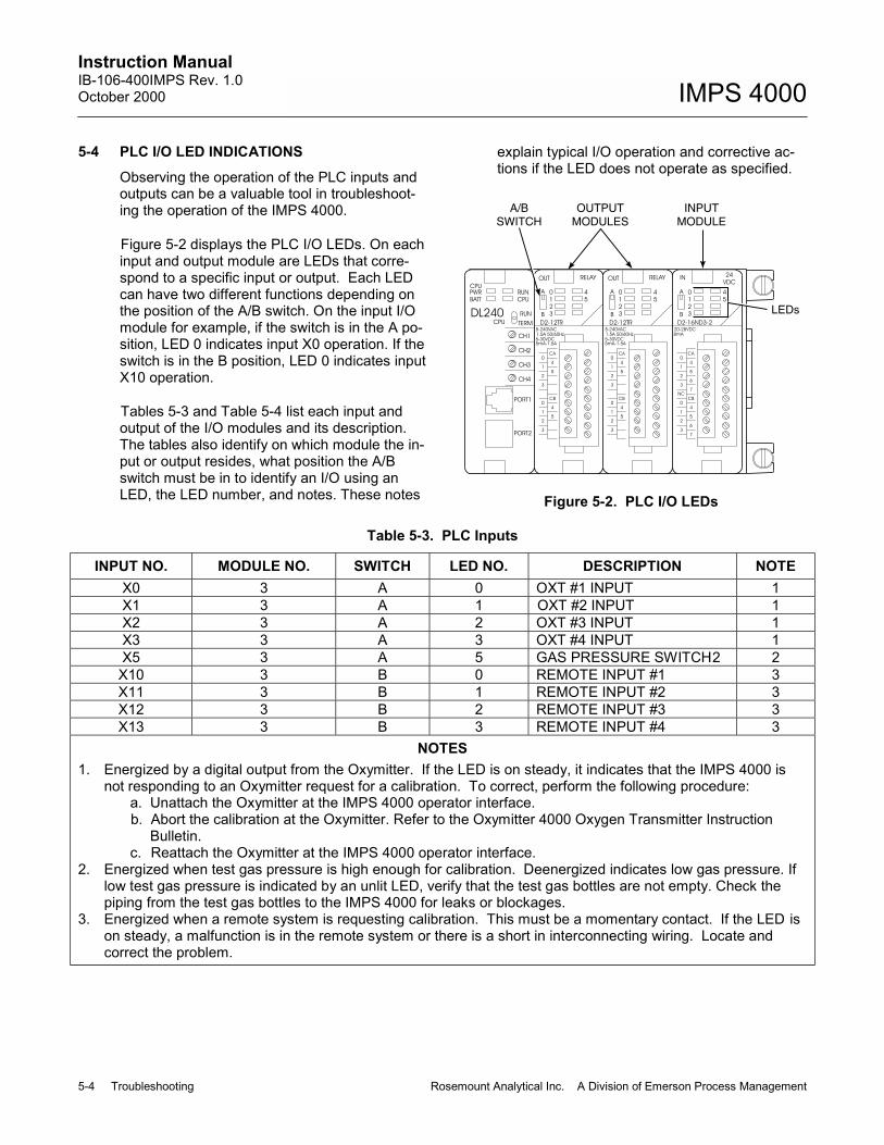
5-4 PLC I/O LED INDICATIONSObserving the operation of the PLC inputs andoutputs can be a valuable tool in troubleshoot-ing the operation of the IMPS 4000.
Figure 5-2 displays the PLC I/O LEDs. On eachinput and output module are LEDs that corre-spond to a specific input or output. Each LEDcan have two different functions depending onthe position of the A/B switch. On the input I/Omodule for example, if the switch is in the A po-sition, LED 0 indicates input X0 operation. If theswitch is in the B position, LED 0 indicates inputX10 operation.
Tables 5-3 and Table 5-4 list each input andoutput of the I/O modules and its description.The tables also identify on which module the in-put or output resides, what position the A/Bswitch must be in to identify an I/O using anLED, the LED number, and notes. These notes
explain typical I/O operation and corrective ac-tions if the LED does not operate as specified.
RELAY IN
DL240CPU
CPU
BATT
PWR
OUT
5mA-1.5A5-30VDC
1.5A 50/60Hz
5-240VAC
D2-12TR
8mA
7
6
7
6
5
4
CA
5
4
CBNC
PORT2
PORT1
3
2
1
0
CH4
CH3
CH2
CH1
3
1
2
0
D2-16ND3-220-28VDC
TERM
RUN
CPU
RUN
2
3
1
0
B
A
VDC
24
5
4
1.5A 50/60Hz
3
2
1
0
5
4
CB
3
2
1
0
5
4
CA
CB
4
5
0
1
2
3
CA
4
5
5-30VDC5mA-1.5A
0
2
1
3
RELAY
3
2
1
0
B
A
5
4 0
3
2
5-240VAC
D2-12TR
A
B
1
OUT
4
5
LEDs
A/BSWITCH
OUTPUTMODULES
INPUTMODULE
Figure 5-2. PLC I/O LEDs
Table 5-3. PLC Inputs
INPUT NO. MODULE NO. SWITCH LED NO. DESCRIPTION NOTEX0 3 A 0 OXT #1 INPUT 1X1 3 A 1 OXT #2 INPUT 1X2 3 A 2 OXT #3 INPUT 1X3 3 A 3 OXT #4 INPUT 1X5 3 A 5 GAS PRESSURE SWITCH2 2X10 3 B 0 REMOTE INPUT #1 3X11 3 B 1 REMOTE INPUT #2 3X12 3 B 2 REMOTE INPUT #3 3X13 3 B 3 REMOTE INPUT #4 3
NOTES1. Energized by a digital output from the Oxymitter. If the LED is on steady, it indicates that the IMPS 4000 is
not responding to an Oxymitter request for a calibration. To correct, perform the following procedure:a. Unattach the Oxymitter at the IMPS 4000 operator interface.b. Abort the calibration at the Oxymitter. Refer to the Oxymitter 4000 Oxygen Transmitter Instruction Bulletin.c. Reattach the Oxymitter at the IMPS 4000 operator interface.
2. Energized when test gas pressure is high enough for calibration. Deenergized indicates low gas pressure. If low test gas pressure is indicated by an unlit LED, verify that the test gas bottles are not empty. Check the piping from the test gas bottles to the IMPS 4000 for leaks or blockages.
3. Energized when a remote system is requesting calibration. This must be a momentary contact. If the LED is on steady, a malfunction is in the remote system or there is a short in interconnecting wiring. Locate and correct the problem.

Instruction Manual106-400IMPS Rev. 1.0
October 2000
Rosemount Analytical Inc. A Division of Emerson Process Management Troubleshooting 5-5
IMPS 4000
Table 5-4. PLC Outputs
INPUT NO. MODULE NO. SWITCH LED NO. DESCRIPTION NOTEY0 1 A 0 OXT #1 INPUT 1Y1 1 A 1 OXT #2 INPUT 1Y2 1 A 2 OXT #3 INPUT 1Y3 1 A 3 OXT #4 INPUT 1Y10 1 B 0 OXT #1 SOLENOID 2,8Y11 1 B 1 OXT #2 SOLENOID 2,8Y12 1 B 2 OXT #3 SOLENOID 2,8Y13 1 B 3 OXT #4 SOLENOID 2,8Y14 1 B 4 GAS 1 SOLENOID 3,9Y15 1 B 5 GAS 2 SOLENOID 3,9Y20 2 A 0 OXT #1 IN CAL 4,10Y21 2 A 1 OXT #2 IN CAL 4,10Y22 2 A 2 OXT #3 IN CAL 4,10Y23 2 A 3 OXT #4 IN CAL 4,10Y24 2 A 4 GAS PRESSURE ALARM 5,10Y30 2 B 0 OXT #1 CAL FAIL 6,10Y31 2 B 1 OXT #1 CAL FAIL 6,10Y32 2 B 2 OXT #1 CAL FAIL 6,10Y33 2 B 3 OXT #1 CAL FAIL 6,10Y34 2 B 4 GAS 1 ON 7,10Y35 2 B 5 GAS 2 ON 7,10
NOTES1. Energized to reply to an Oxymitter. A pulse or a series of pulses will be observed, depending on what portion
of the calibration cycle is being performed. If the LED is on steady, it may indicate a PLC failure. Before replacing the PLC, reset the PLC by powering down and powering up the IMPS 4000. Monitor the gas application portion of the calibration cycle once again. If the LED is still on steady, replace the PLC.
2. Energized to select which Oxymitter will receive test gas during calibration. It is only energized during the gasapplication portion of the calibration cycle.
3. Energized to apply either test gas. It is only energized during the gas application portion of the calibrationcycle.
4. Energized when an Oxymitter is in calibration.5. Energized if gas pressure is low.6. Energized if a calibration has failed.7. Energized when a test gas is flowing.8. If energized continuously, reset by unattaching and reattaching the Oxymitter at the IMPS 4000 operator
interface.9. If energized longer than the AbrtTim set at the operator interface, reset using the following procedure:
a. Unattach the Oxymitter at the IMPS 4000 operator interface.b. Abort the calibration at the Oxymitter. Refer to the Oxymitter 4000 Oxygen Transmitter Instruction Bulletin.c. Reattach the Oxymitter at the IMPS 4000 operator interface.
10. If the output LED is illuminated but the remote indication is off, check the wiring from the IMPS 4000 to the remote device. Make sure the wiring is in accordance with Figure 2-3. Note that the status outputs from the IMPS 4000 have shared common connections and remote power is required.

Instruction ManualIB-106-400IMPS Rev. 1.0October 2000
5-6 Troubleshooting Rosemount Analytical Inc. A Division of Emerson Process Management
IMPS 4000

Instruction Manual106-400IMPS Rev. 1.0
October 2000
Rosemount Analytical Inc. A Division of Emerson Process Management Replacement Parts 6-1
IMPS 4000
SECTION 6RETURN OF MATERIAL
6-1 If factory repair of defective equipment isrequired, proceed as follows:
a. Secure a return authorization from aRosemount Analytical Sales Office or Rep-resentative before returning the equipment.Equipment must be returned with completeidentification in accordance with Rosemountinstructions or it will not be accepted.
In no event will Rosemount be responsiblefor equipment returned without properauthorization and identification.
b. Carefully pack the defective unit in a sturdybox with sufficient shock absorbing materialto ensure no additional damage occursduring shipping.
c. In a cover letter, describe completely:
1. The symptoms that determined theequipment is faulty.
2. The environment in which the equip-ment was operating (housing, weather,vibration, dust, etc.).
3. Site from where the equipment wasremoved.
4. Whether warranty or nonwarrantyservice is requested.
5. Complete shipping instructions for thereturn of the equipment.
d. Enclose a cover letter and purchase orderand ship the defective equipment accordingto instructions provided in a RosemountReturn Authorization, prepaid, to:
Rosemount Analytical Inc.RMR Department1201 N. Main StreetOrrville, Ohio 44667
If warranty service is requested, the defec-tive unit will be carefully inspected andtested at the factory. If failure was due toconditions listed in the standard Rosemountwarranty, the defective unit will be repairedor replaced at Rosemount's option, and anoperating unit will be returned to the cus-tomer in accordance with shippinginstructions furnished in the cover letter.
For equipment no longer under warranty,the equipment will be repaired at the factoryand returned as directed by the purchaseorder and shipping instructions.

Instruction ManualIB-106-400IMPS Rev. 1.0October 2000
6-2 Replacement Parts Rosemount Analytical Inc. A Division of Emerson Process Management
IMPS 4000

Instruction Manual106-400IMPS Rev. 1.0
October 2000
Rosemount Analytical Inc. A Division of Emerson Process Management Return of Material 7-1
IMPS 4000
SECTION 7REPLACEMENT PARTS
Table 7-1. Replacement Parts for the IMPS 4000
FIGURE andINDEX No. PART NUMBER DESCRIPTION
4-1, 8, 9, and10
3D39435G01* Solenoid
4-1, 44 1A97913H03 Fuse, 5A @ 250 Vac, Slow Blow4-1, 34 771B635H01* Flowmeter Assembly - Test Gas4-1, 35 771B635H02* Flowmeter Assembly - Reference Gas
1A98631 Probe Adder Kit4-1, 29 1A97953H01* Hose Adapter
4847B46H01* Tubing Length4847B46H02* Tubing Length4847B46H03* Tubing Length4847B46H04* Tubing Length
1-3 7307A56G02 Check Valve4-1, 33 1A98972H01 Operator Interface4-1, 25 PLC
1A98969H01 PLC 4-Slot Base, 110/220 VDC Power Supply1-2 1A98967H01 CPU
1A98968H01 CPU Battery5-2 1A98970H01 DC Input Module5-2 1A98971H01 Relay Output Module4-1, 22 3D39681G01 PC Board
*These items are included in the probe adder kit.

Instruction ManualIB-106-400IMPS Rev. 1.0October 2000
7-2 Return of Material Rosemount Analytical Inc. A Division of Emerson Process Management
IMPS 4000
Instruction Manual106-400IMPS Rev. 1.0
October 2000
Rosemount Analytical Inc. A Division of Emerson Process Management Index 8-1
IMPS 4000
SECTION 8INDEX
This index is an alphabetized listing of parts, terms, and procedures having to do with the Haz-ardous Area Oxygen/Combustibles Transmitter. Every item listed in this index refers to a locationin the manual by one or more page numbers.
AAmbient Temperature Range, 1-3, 2-2AMS, 3-5Automatic Calibration, 1-1, 3-5
CCabling Distance, 1-3Calibration Parameters, 3-3, 3-4Change Presets Display Mode, 3-2, 3-3, 3-4, 5-3CPU, 1-2, 1-3
DDrain Valve, 1-2
EElectrical Connections, 2-2Electrical Connections, 2-3
FFlow Panel, 1-2, 1-3Flowmeter, 1-2, 1-3, 3-5, 4-4Fuse, 4-1, 5-1, 5-2
GGas Connections, 2-2
HHandshake Signal, 1-3, 5-3HART, 3-5Heater, 1-2, 1-3, 2-2
II/O Module, 1-2, 1-3, 5-4Inner Assembly, 1-2, 1-3Input Power, 1-3, 2-3, 5-2
LLEDs, 5-4, 5-5Line Voltage, 2-3, 2-4, 5-2
MManifold, 1-2, 1-3Mechanical Installation, 2-1Membrane Keypad, 3-2Message Display Mode, 3-2, 3-3, 3-4
NNEMA 4X (IP56) Enclosure, 1-2
OOperator Interface, 4-3Operator Interface, 1-2, 3-2, 3-3, 3-4, 5-4, 5-5Oxymitter Logic I/O, 1-4, 2-3, 2-4, 3-5, 5-3
PPC Board, 1-2, 1-3, 5-2PLC, 1-2, 1-3, 4-1, 4-2, 5-1, 5-2, 5-4Power Supply, 1-2, 1-3, 2-4, 5-1Pressure Regulator, 4-4Pressure Regulator, 1-2, 1-3, 2-2Pressure Switch, 1-2, 1-3
RReference Gas, 1-2, 1-3, 1-4Remote Contact, 2-3, 2-4, 3-5Return Equipment, 7-1
SSemi-Automatic Calibration, 3-5Semi-automatic Calibration, 1-1Solenoid, 1-2, 1-4, 1-6, 4-3, 5-1, 5-2Status Relay Connections, 2-3, 2-4
TTest Gas, 1-2, 1-3, 1-6, 2-2, 3-1, 3-5, 5-1, 5-2, 5-3,
5-4, 5-5
WWeight, 1-3
ZZ-Purge, 1-5, 1-6

Instruction ManualIB-106-400IMPS Rev. 1.0October 2000
8-2 Index Rosemount Analytical Inc. A Division of Emerson Process Management
IMPS 4000

29453440/10-00
WARRANTY
Goods and part(s) (excluding consumables) manufactured by Seller are warranted to be free fromdefects in workmanship and material under normal use and service for a period of twelve (12)months from the date of shipment by Seller. Consumables, glass electrodes, membranes, liquidjunctions, electrolyte, o-rings, etc., are warranted to be free from defects in workmanship andmaterial under normal use and service for a period of ninety (90) days from date of shipment bySeller. Goods, part(s) and consumables proven by Seller to be defective in workmanship and/ormaterial shall be replaced or repaired, free of charge, F.O.B. Seller's factory provided that thegoods, part(s) or consumables are returned to Seller's designated factory, transportation chargesprepaid, within the twelve (12) month period of warranty in the case of goods and part(s), and inthe case of consumables, within the ninety (90) day period of warranty. This warranty shall be ineffect for replacement or repaired goods, part(s) and the remaining portion of the ninety (90) daywarranty in the case of consumables. A defect in goods, part(s) and consumables of the com-mercial unit shall not operate to condemn such commercial unit when such goods, part(s) andconsumables are capable of being renewed, repaired or replaced.
The Seller shall not be liable to the Buyer, or to any other person, for the loss or damage directlyor indirectly, arising from the use of the equipment or goods, from breach of any warranty, or fromany other cause. All other warranties, expressed or implied are hereby excluded.
IN CONSIDERATION OF THE HEREIN STATED PURCHASE PRICE OF THE GOODS,SELLER GRANTS ONLY THE ABOVE STATED EXPRESS WARRANTY. NO OTHER WAR-RANTIES ARE GRANTED INCLUDING, BUT NOT LIMITED TO, EXPRESS AND IMPLIEDWARRANTIES OR MERCHANTABILITY AND FITNESS FOR A PARTICULAR PURPOSE.
Limitations of Remedy. SELLER SHALL NOT BE LIABLE FOR DAMAGES CAUSED BY DE-LAY IN PERFORMANCE. THE SOLE AND EXCLUSIVE REMEDY FOR BREACH OF WAR-RANTY SHALL BE LIMITED TO REPAIR OR REPLACEMENT UNDER THE STANDARDWARRANTY CLAUSE. IN NO CASE, REGARDLESS OF THE FORM OF THE CAUSE OF AC-TION, SHALL SELLER'S LIABILITY EXCEED THE PRICE TO BUYER OF THE SPECIFICGOODS MANUFACTURED BY SELLER GIVING RISE TO THE CAUSE OF ACTION. BUYERAGREES THAT IN NO EVENT SHALL SELLER'S LIABILITY EXTEND TO INCLUDE INCIDEN-TAL OR CONSEQUENTIAL DAMAGES. CONSEQUENTIAL DAMAGES SHALL INCLUDE, BUTARE NOT LIMITED TO, LOSS OF ANTICIPATED PROFITS, LOSS OF USE, LOSS OF REVE-NUE, COST OF CAPITAL AND DAMAGE OR LOSS OF OTHER PROPERTY OR EQUIPMENT.IN NO EVENT SHALL SELLER BE OBLIGATED TO INDEMNIFY BUYER IN ANY MANNERNOR SHALL SELLER BE LIABLE FOR PROPERTY DAMAGE AND/OR THIRD PARTY CLAIMSCOVERED BY UMBRELLA INSURANCE AND/OR INDEMNITY COVERAGE PROVIDED TOBUYER, ITS ASSIGNS, AND EACH SUCCESSOR INTEREST TO THE GOODS PROVIDEDHEREUNDER.
Force Majeure. Seller shall not be liable for failure to perform due to labor strikes or acts beyondSeller's direct control.

Instruction ManualIB-106-400IMPS Rev. 1.0October 2000
© Rosemount Analytical Inc. 2001
IMPS 4000
Emerson Process ManagementRosemount Analytical Inc.Process Analytic Division1201 N. Main St.Orrville, OH 44667-0901T (330) 682-9010F (330) 684-4434E [email protected]
ASIA - PACIFICFisher-RosemountSingapore Private Ltd.1 Pandan CrescentSingapore 128461Republic of SingaporeT 65-777-8211F 65-777-0947http://www.processanalytic.com
Fisher-Rosemount GmbH & Co.Industriestrasse 163594 HasselrothGermanyT 49-6055-884 0F 49-6055-884209
EUROPE, MIDDLE EAST, AFRICAFisher-Rosemount Ltd.Heath PlaceBognor RegisWest Sussex PO22 9SHEnglandT 44-1243-863121F 44-1243-845354
LATIN AMERICAFisher - RosemountAv. das Americas3333 sala 1004Rio de Janeiro, RJBrazil 22631-003T 55-21-2431-1882
IMPS 4000
Part no.____________
Serial no.____________
Order no.____________