improvised munitions black bookpyrobin.com/files/improvised munitions3.pdfimprovised munitions black...
TRANSCRIPT
Improvised Munitions
Black Book · Volume 2
Desert Publications ElDorado, AR 71731-1751
Improvised Munitions Black Book Volume2
© 1981 by Desert Publications P.O. Box 1751
ElDorado, AR 71731-1751 501-862-2077
Printed in U. S. A. ISBN 0-87947-205-7
109 87 65
Desert Publication is a division of The DELTA GROUP, Ltd.
Direct all inquires & orders to the above address.
All rights reserved. Except of use in a review, no portion of this book
may be reproduced by any means known or unknown without the
expressed written permission of the publisher.
Neither the author nor the publisher assumes any responsibility for the
use or misuse of the information contained in this book.
II
Improvised Munitions
Black Book Volume 2
Section Page
IV Mortars, Rockets, & Launchers 1
v Incendiary Devices 25
VII Fuses, Detonators & Delay Mechanisms 77
VIII Miscellaneous Improvised Munitions 123
All information compiled by
Frankford Arsenal Philadelphia, Pennsylvania
Also available Improvised Munitions Black Book Vol. 3 Only $18.95 + $4.95 Shipping & Handling
Ill
FOR OFFICIAL USE ONLY
RECOILLESS LAUNCHER
Section IV No.1
A dual directional scrap fragment launcher which can be placed to cover the path of advancing troops.
MATERIAL REQUIRED:
Iron water pipe approximately 4 ft. (1 meter) long and 2 to 4 in. (5 to 10 em) in diameter
Black powder (commercial) or salvaged artillery propellant about 1/2 lb. (200 gms)
Safety or improvised fuse (Section VI, No. 7) or improvised electrical igniter (Section VI, No. 2)
Stones and/or metal scrap chunks approximately 1/2 in. (1 em) in diam-eter - about 1 lb. (400 gms) total
4 rags for wadding, each about 20 in. by 20 in. (50 em by 50 em) Wire Paper or rag
NOTE: Be sure that the water pipe bas no cracks or flaws.
1
FOR OFFICIAL USE ONLY
PROCEDURE:
1. Place propellant and Igniter In paper or rag and tie with string so contents cannot fall out.
Packaged
2. Insert packaged propellant and Igniter In center of pipe. leads out one end of pipe.
3. Stuff a rag wad,. into each end of pipe and lightly tamp using a flat end stick.
4. Insert stones and/ or scrap metal into each end of pipe. Be sure the same weight of material is used In each side.
Stones and
Stones and Packaged Scrap Metal Propellant
5. Insert a rag wad Into each end of the pipe and pack tightly as before.
HOW TO USE:
1. Place scrap mine In a tree or pointed In the path of the enemy. Attach Igniter lead to the firing circuit. The recoilless launcher Is now ready to fire.
2. If safety or Improvised fuse is used instead of the detonator, place the fuse Into the packaged propellant through a hole drilled In the center of the pipe. Light free end of fuse when ready to fire. Allow for normal delay time.
CAUTION: Scrap will be ejected from both ends of the launcher.
2
SHOTGUN GRENADE LAUNCHER
Section IV No.2
This device can be used to launch a hand grenade to a distance of 160 yards (150 meters) or more. using a standard 12 gauge shotgun.
MATERIAL REQUIRED:
Grenade (Improvised pipe hand grenade, Section II. No. l, msy be used) 12 gauge shotgun 12 gauge shotgun cartridges Two washers, (brass, steel. iron, etc. ) , having outside diameter of
5/8 ln. (1-1/2 em) Rubber disk 3/4 ln. (2 em) In diameter and 1/4 ln. (6 mm) thick (leather,
neoprene, etc. can be used) A 30 in. (75 em) long piece of hard wood (maple, oak, etc.) approxi
mately 5/8 In. ( 1-1/2 em) In diameter. Be sure that wood will slide Into barrel easily.
Tin can (grenade and Its safety lever must fit into can) Two wooden blocks about 2 ln. (5. em) square and 1-1/2 in. (4 em) thick One wood screw about lin. (2-1/2 em) long Two nails about 2 in. (5 em) long 12 gauge wads, tissue paper, or cotton Adhesive tape, string, or wire Drlll
PROCEDURE:
1. Punch hole In center of rubber disk large enough for screw to pass through.
2. Make push-rod as shown.
Disk
NOTE: Gun barrel is slightly less than 3/4 Inch In diameter. If rubber disk does not fit in barrel. file or trim it very slightly. It should fit tightly.
3. Drill a hole through the center of one wooden block of such size that the push-rod will fit tightly. Whittle a depression around the hole on one side approximately 1/8 in. (3 mm) and large enough for the grenade to rest in.
3
4 . Place the base of the grenade in the depression in the wooden block. Securely fasten grenade to block by wrapping tape (or wire) around entire grenade and block.
NOTE: Be sure that the tape (or wire) does not cover hole in block or interfere with the operation of the grenaqe safety lever.
5. !?rill hole through the center of the second wooden block, so that it will just slide over the outside of the gun barrel.
~. Drlll a hole in the center of the bottom of the tin can the same size as the hole in the block.
7. Attach can to block as shown.
Hole in Block
Nail
8. Slide the can and block onto the barrel until muzzle passes can open end. Wrap a small piece of tape around the bar-rl!! an inch or two from the end. Tightly wrapped string may be use.d instead of tape. Force the can and wooden block forward against the tape so that they are securely held in place. Wrap tape around the barrel behind the can.
4
CAUTION: Be sure that the can Is securely fastened to the gun barrel. If t.'le can should become loose and slip down the barrel after the launcher is assembled, the grenade will explode after the regular delay time.
9. Remove crimp from a 12 gauge shotgun cartridge with pen knife. Open cartridge. Pour shot from shell. Remove wads and plastic liner if present.
10. Empty the propellant onto a piece of paper. Using a knife, divide the propellant In half. Replace half of the propellant into the cartridge case.
11. Replace the 12 gauge cardboard wads into cartridge case.
NOTE: If wads are not available, stuff tissue paper or cotton into the cartridge case. Pack tightly.
HOW TO USE:
3 Cardboard Wads
1/2 Original Propellant
~Tissue Paper - ~~
Method I - When ordinary grenade is used:
1. Load cartridge in gun.
2. Push end of push -rod without the rubber disk into hole in wooden block fastened to grenade.
5
3. Slowly push rod into barrel until it rests against the cartridge case and grenade is in can. If the grenade is not in the can, remove rod and cut to proper size. Push rod back into barrel.
4. With can holding safety lever of grenade in place, carefully remove safety pin.
CAUTION: Be sure that the sides of the can restrain the grenade safety lever. If the safety lever should be released for any reason, grenade will explode after regular grenade delay time.
5. To fire grenade launcher, rest gun in ground at angle determined by range desired. A 45 degree angle should give about 150 meters (160 yds.).
Method II - When improvised pipe grenade is used:
An improvised pipe grenade (Section II, No. 1) may be launched in a similar manner. No tin can is needed.
1. Fasten the grenade to the block as shown above with the fuse hole at the end opposite the block.
2. Push end of push-rod Into hole in wooden block fastened to grenade.
3. Push rod into barrel until it rests against cartridge case.
6

4. Load cartridge in gun.
5. Follow step 5 of Method I.
6. Using a fuse with at least a 10 second delay, light the fuse before firing.
7. Fire when the fuse burns to 1/2 ite original length.
7

8
FOR OFFICIAL USE ONLY
Section lV No.3
GRENADE LAUNCHER (57 MM CARDBOARD CONTAINER)
An improvised method of launching a standard grenade !50 yds. (135 meters) or an improvised grenade 90 yds. (81 meters) using a discarded cardboard ammunition container.
MATERIAL REQUIRED:
Heavy cardboard container with inside diameter of 2-1/2 to 3 in. (5-1/2 to 8 em) and at least 12 in. (30 em) long (ammunition container is suitable)
Black powder - 8 grams (124 grains) or less Safety or improvised fuse (Section VI, No. 7) Grenade (Improvised hand grenade, Section II, No. 1 may be used) Rsg, approximately 30 in. x 24 in. (75 em x 60 em) Paper
CAUTION: 8 grams of black powder yield the maximum ranges. Do not use more than this amount. See Improvised Scale, Section VII, No. 8, for measuring.
PROCEDURE: METHOD I- If Standard Grenade is Used.
1. Discard top of container. Make small hole in bottom.
2. Place bla.ck powder in paper. Tie end with string so contents cannot fall out. Place package in container.
9
3. Insert rag wadding into container. Pack tightly with CAUTION.
4. Measure off a length of fuse that will give the desired delay. Thread this through hole in bot-tom of container so that it penetrates into the black powder package.
Fuse Black Powder Package
Rag Wadding
NOTE: If improvised fuse is used, be sure fuse fits loosely through hole in bottom of container.
' •m•~h·~·~~~• t-carefully withdraw safety pin from "'~" fuoort ..., ... "" ~- w~.: tainer, lever end first. '
Black Powder Grenade Package
CAUTION: If grenade safety lever should be released for any reason, grenade will explode after normal dela time.
6. Bury container about 6 in. (15 em) in the ground at 30" angle, bringing fuse up alongside container. Pack ground J!g~y around container.
CAUTION: The tightly packed dirt helps tc hold the tube together during the firing. Do not fire unless at least the bottom half of the container is burted in solidly packed dirt.
METHOD ll - If Improvised Pipe Hand Grenade is Used.
I. Follow step I of above ·procedure.
10
FOR OFFICIAL USE ONLY
2. Measure off a piece of fuse at least as lonl( as the cardboard con-tainer. Tape one end of this to the fuse from the blasting cap in the improvised grenade. Be sure ends of fuse are in contact with each other.
Fuse Connected to Blasting Cap in Grenade
Tape
3. Place free end of fuse and black powder on piece of paper. Tie ends with string so contents will not fall out.
Black Powder
4. Place package in tube. Insert rag wadding. Pack so it fits snugly. Place pipe hand grenade into tube. Be sure it fits snugly.
Package
5. Insert fuse through hole in end of cardboard container. Be sure it goes into black powder package.
NOTE: Cardboard container may be used for only one firing.
6. Follow step G of Method I.
HOW TO USE:
Light fuse when ready to fire.
11
Rag Wadding
Black Powder Package
Pipe Hand Grenade

12
FOR OFFICIAL USE ONLY
FIRE BOTTLE LAUNCHER
Section IV No. 4
A device using 2 items (shotgun and chemical fire bottle) that can be used to start or place a fire 80 yards (72 meters) from laiDlcher.
MATERIAL REQUIRED:
Standard 12 gauge or improvised shotgun (Section m, No. 2) Improvised fire bottle (Section V, No. 1)
Tin can, about 4 in. (10 em) in diameter and 5-1/2 ln. (14 em) high Wood, about 3 in. x 3 ln. x 2 in. (7-1/2 em x 7-1/2 em x 5 em) Nail, at least 3 ln. (7-1/2 em) long Nuts and bolts or nails, at least 2-1/2 in. (6-1/2 em) long Rag Paper Drill
If Standard Shotgun is Used:
Hard wood stick, about the same length as shotgun barrel and about 5/8 in. (1-1/2 em) in diameter. Stick need not be roiDld.
2 washers (brass, steel, iron, etc.) having outside diameter of 5/8 in. (1-1/2 em)
One wood screw about 1 in. (2-1/2 em) long Rubber disk, 3/4 in. (2 em) in diameter and 1/4 ln. (6 mm) thick,
leather, cardboard, etc. can be used. 12 gauge shotgun ammunition
If Improvised Shotgun is Used:
Fuse, safety or Improvised fast burning (Section VI, No. 7) Hard wood stick, about the same length as shotgun barrel and 3/4
In. ( 2 ern) in diameter Black powder- 9 grams (135 grains). See Section VU, No. 8.
13
FOR OFFICIAL USE ONLY
PROCEDURE:
METHOD I - If Improvised Shotgun is Used:
1. DrUl hole in center of wood block approximately lin. (2-1/2 em) deep. Hole should have approximately the same diameter as the wooden stick.
2. DrUl 2 small holes on opposite sides of the wooden block. Hole should be large enough for bolts to pass through.
3. Fasten can to block with nuts and bolts.
NOTE: Can may also be securely fastened to block by hammering several nails through can and block. Do not drill boles, and be careful not to split wood.
4. Place wooden stick into hole in wooden block. Drill small hole (same diameter as that of 3 in. nail) through wooden block and through wooden stick. lnsert nail in hole.
14
2 Small
FOR OFFICIAL USE ONLY
5. Crwnple paper and place in bottom of can. Place another piece of paper aroiUld fire bottle and insert in can. Use enough paper so thst bottle will fit snugly.
6. Place safety fuse and black powder on paper. Tie each end with string.
Paper
Fire Bottle
~:>'"'--Safety Fuse
7. Thread fuse through hole in plug. Place powder package in rear of shotg\Ul. Screw plug finger tight into coupling.
NOTE: Hole in plug may have to be enlarged for fuse.
Black Powder
15
FOR OFFICIAL USE ONLY
8. Insert rag into front of shotgun. Pack rag against powder package with stick. USE CAUTION.
METHOD 11 - If Standard Shotgun Is Used:
1. Follow Steps 1 and 2, Shotgun Grenade LaUDcher, Section IV, No. 2.
2. Follow procedure of Method I, Steps 1- 5.
3. Follow Steps !1, 10, 11, Shotgun Grenade LaiDicher, Section IV, No. 2, using 1/3 of total propellant Instead of 1/2.
4. Load cartridge in gun.
HOW TO USE:
1. lnsert stick and holder containing chemical fire bottle.
JcAUTlON: Do not tilt muzzle downward.J
Safety Fuse Pipe Plug
2. Hold gun against groiDtd at 45• angle and light fuse.
Safety
NOTE: Steps 1 and 2, "HOW TO USE," same for both standard and Improvised shotguns.
CAUTION: Severe burns may result If bottle shatters when fired. If possible, obtsin a bottle Identical to that being used as the fire bottle. Fill about 2/3 full of water and fire as above. If bottle shatters when fired Instead of being launched Intact, use a different type of bottle.
16
FOR OFFICIAL USE ONLY
GRENADE LAUNCHERS
Section IV No.5
A variety of grenade launchers can be fabricated from metal pipes and fittings. ~nges up to 600 meters (660 yards) can be obtained depending on length of tube, charge, number of grenades, and angle of firing.
MATERIAL REQUIRED:
Metal pipe, threaded on one end and approximately 2-1/2 in. (6-1/4 em) Ill diameter and 14 ln. to 4 ft. (35 em to 119 em) long depending on range desired and n\llllber of grenades used.
Eqd cap to fit pipe Black powder, 15 to 50 gm, approximately 1-1/4 to 4-1/4 tablespoons
(Section I, No. 3) Safety fuse, fast burning improvised fuse (Section VI, No. 7) .2!:
improvised electric bulb initiator (Section VI, No. 1 Automobile light bulb Is needed)
Grenade(s) - 1 to 6 Rag(s) - about 30 in. x 30 in. (75 em x 75 em) and 20 in. x 20 ln.
(55 em x 55 em) Drill String
NOTE: Examine pipe carefully to be sure there are no cracks or other !laws.
PROCEDURE:
METHOD I - If Fuse is Used:
1. Drill small hole through center of end cap.
2. Make smalllmot near one end of fuse. Place black powder and lmotted end of fuse In paper and tie with string.
End Cap
17
FOR OFFICIAL USE ONLY
3. Thread fuse through hole in end cap and place package in end cap. Screw end cap onto pipe, being careful that black powder package is not caught between the threads.
4. Roll rag wad so that it is about 6 in, (15 em) long and has approximately the same diameter as the pipe. Push rolled rag into openend of pipe until it rests against black powder package.
5. Hold grenade safety lever in place and carefully withdraw safety pin.
Black Powder Package
CAUTION: If grenade safety lever is released for any reason, grenade will explode after regular time. (4- 5 sec.)
6, Holding safety lever in place, carefully push grenade into pipe, lever end first, until it rests against rag wad.
18
FOR OFFICIAL USE ONLY
7. The following table lists various types of grenade launchers and their performance characteristics.
NO. OF BLACK DESIRED GRENADES POWDER PIPE FIRING
RANGE LAUNCHED CHARGE LENGTH ANGLE
250m 15gm 14" 30°
500 m 50 gm 48" 10°
600 m (a) 1 50gm 48" 30°
200m 6 (b) 25gm 48" 30°
(a) For this range, an additional delay Is required. See Section VI, No. 11 and 12.
(b) For multiple grenade launcher, load as shown.
NOTE: Since performance of different black powder varies, fire several test rounds to determine tbe exact amount of powder necessary to achieve the des ired range.
HOW TO USE:
Stuffed Rag (20 X 20)
Black Powder Package
1. Bury at least 1/2 of tbe launcher pipe In tbe ground at desired angle. Open end should face the expected path of the enemy. Muzzle may be covered witb cardboard and a thin layer of diri and/or leaves as camouflage. Be sure cardboard prevents diri from entering pipe.
19
Cardboard and Leaves
FOR OFFICIAL USE ONLY
NOTE: The 14 ln. launcher may be hand held against the ground Instead of being buried.
2. Light fuse when ready to fire.
METHOD II - If Electrical Igniter is Used:
NOTE: Be sure that bulb is In good operating condition.
1. Prepare electric bulb Initiator as described In Section VI, No. 1.
2. Place electric Initiator and black powder charge in paper. Tie ends of paper with string.
3. Follow above Procedure, steps 3 to end.
HOW TO USE:
1. Follow above How to Use, Step 1.
2. Connect leads to firing circuit. Close circuit when ready to fire.
20
FOR OFFICIAL USE ONLY
Section IV No.6
60 MM MORTAR PROJECTILE LAUNCHER
A device to laiUich 60 mm mortar roiUids using a metal pipe 2-1/2 in. (6 em) in diameter and 4ft. (120 em) long as the laiUicbing tube.
MATERIAL REQUIRED:
Mortar, projectile (60 mm) and charge Increments Metal pipe 2-1/2 in. (6 em) In diameter and 4 ft. (120 em) long, threaded
on one end Threaded end cap to fit pipe Bolt, 1/8 in. (3 mm) in diameter and at least 1 ln. (2-1/2 em) long Two (2) nuts to fit bolt File Drill
PROCEDURE:
1. Drill hole 1/8 in. (3 mm) in diameter through center of end cap.
2. RoiUid off end of bolt with file.
3. Place bolt through hole In end cap. Secure in place with nuts as illustrated.
21
RoiUided End
t}m•om•m!!mm!IIIA
End Cap
FOR OFFICIAL USE ONLY
4. Screw end cap onto pipe tightly. Tube is now ready for use.
HOW TO USE:
1. Bury launching tube in ground at desired angle so that bottom of tube is at least 2 ft. (60 em) under- • :-.: . ground. Adjust the num- _, .• :--- 2 Feet ber of increments in rear - • or more finned end of mortar projec- _. 1
tile. See following table • .:.- ·•:=:::::::::==:--....:!t--for laWlching angle and . number of Increments used.
2. When ready to fire, withdraw safety wire from mortar projectile. Drop projectile Into launching tube, ~ END FIRST.
CAUTION: Be sure bore riding pin is In place In fuse when mortar projectile is dropped into tube. A live mortar round could explode In the tube if the fit is loose enough to permit the bore riding pin to come out partway.
Mortar Projectile
~ Bore Riding Pin
CAUTION: The round will fire as soon as the projectile is dropped into tube. Keep sll parts of body behind the open end of the tube.
22
FOR OFFICIAL USE ONLY
DESIRED MAXIMUM REQUIRED CHARGE-
RANGE HEIGHT ANGLE OF NUMBER OF (YARDS) MORTAR ELEVATION INCREMENTS
WILL OF TUBE REACH (MEASURED (YARDS) FROM HORI-
ZONTAL DEGREES)
150 25 40 0
300 50 40 1
700 150 40 2
1000 225 40 3
1500 300 40 4
125 75 60 0
300 125 60
550 250 60 2
1000 375 60 3
1440 600 60 4
75 100 80 0
150 200 80
300 350 80 2
400 600 80 3
550 750 80 4
23

24
CHEMICAL FIRE BOTTLE
Section V No. 1
This incendiary bottle is self-igniting on target impact,
MATERIALS REQUIRED
How Used Common Source
Sulphuric Acid Storage Batteries Motor Vehicles Material Proces- Industrial Plants sing
Gasoline Motor Fuel Gas Station or Motor Vehicles
Potassium Chlorate Medicine Drug Store
Sugar Sweetening Foods Food Store
Glass bottle with stopper (roughly 1 quart siz:e), Small Bottle or jar with lid, Rag or absorbent paper (paper towels, newspaper), String or rubber bands,
PROCEDURE
1. Sulphuric Acid Must be Concentrated. If battery acid or other dilute acid is used, concentrate it by boiling until dense white fumes are given off, Container used should be of enamelware or oven glass.
CAUTION
Sulphuric acid will burn skin and destroy clothing. If any is spilled, wash it away with a large quantity of water. Fumes are also dangerous and should not be inhaled.
z. Remove the acid from heat and allow to cool to room temperature.
25
3. Pour gasoline into the large (1 quart) bottle until it is approximately Z/3 full.
4. Add concentrated sulphuric acid to gasoline slowly until the bottle is filled to within 1" to Z" from top. Place the stopper on the bottle.
5. Wash the outside of the bottle thoroughly with clear water.
CAUTION
If this is not done, the fire bottle may be dangerous to handle during use.
6. Wrap a clean cloth or several sheets of absorbent paper around the outside of the bottle. Tie with string or fasten with rubber bands.
Gasoline 8c Cap Sulphuric Acid
Absorbent Paper StriJII
7. Dissolve 1/Z cup (100 gm) of potauium chlorate and 1/Z cup (100 gm·) of sugar in one cup (ZSO cc) of boiling water.
8. Allow the solution to cool, pour into the small bottle and cap tightly. The cooled solution should be approx. Z/3 crystals and 1/3 liquid. If there is more liquid than this, pour off excess before using.
CAUTION
Store this b'~ttle separately from the other bottle.
HOW TO USE
1. Shake the small bottle to mix contents and pour onto the cloth or paper around the large bottle.
Bottle can be used wet or after solution has dried. However, when dry, the sugar - Potassium chlorate mixture is very sensitive to spark or flame and should be handled accordingly.
z. Throw or launch the bottle. When the bottle breaks against a hard surface (target) the fuel will ignite.
26
Section V No. 2
IGNITER FROM BOOK MATCHES
This is a hot igniter made from paper book matches for use with molotov cocktail and other incendiaries.
Material Required
Paper book matches. Atihesive or friction tape.
Procedure
1. Remove. the staple(s) from match book and separate matches from cover.
Z. Fold and tape one row of matches.
3. Shape the cover into a tube with striking surface on the inside and tape. Make sure the folded cover will fit tightly around the taped match heads. Leave cover open at opposite end for insertion of the matches.
~ --·/ LUIHTIR
~ tUIOLI 1t0W OP •ATCHU ~
~·-TAPIO MAn:Mll
OPt• a•
4. Push the taped matches in- ~~::.. to the tube until the bottom ~. . .... ends are exposed about 3/4 in. (Z em).
27
5. Flatten and fold the open end of the tube so that it laps over about 1 in. (2-1 I 2 em); tape in place.
Use With Molotov Cocktail
Tape the "match end tab" of the igniter to the neck of the molotov cocktail.
Grasp the "cover end tab" and pull sharply or quickly to ignite.
General Use
The book match igniter can be used by itself to ignite flammable liquids, fuse cords and similar items requiring hot ignition.
CAUTION
Store matches and completed igniters in moistureproof containers such as rubber or plastic bags until ready for use. Damp or wet paper b~k matches will not ignite.
28
MECHANICALLY INITIATED FUU: BOTTLE
Section V No. 3
The mechuically bdtiated Fire Bottle i• an incendiary device which lplte• when thrown asain•t a hard •urface.
MATEJUALS ltEQUIItED
Gla .. jar or ehol't neck bottle with a leakproof lid or •topper.
"'fin" cu or •imilar container Ju•t lar,. enou1h to fit over the lid of the jar.
Coil eprins (compn .. ion) approximately 1/2. the cllameter of the cu and 1 1/2. time• a• lens.
Ga•olille Four (4) ''blue tip" matche• Flat •tick or piece of metal
(roushly J/2." ~ 1/1~" x 4") Win or heavy twine Adhe•i ve tape
PltOCEDUltE
1, Draw Ol' 8CI'&tch two line11 around the can • eme 3/4" (19 mm) ud the other 1 1/4" (30 mm) from the open end,
z.. Cut 2. •lot• on oppo•tte •ide• of the tin can at the line farthe•t fl'am the open end, M~ lllote lar1e anoush for the flat 8tlck or piece of metal to pa .. tha-oup.
29
3. Punch Z small holes just below the rim of the open end of the can.
4. Tape blue tip matches together in pairs. The distance between the match heads should equal the inside diameter of the can. Two pairs are sufficient.
5. Attach paired matches to second and third coils of the spring, using thin wire.
6. Insert the end of the spring opposite the matches into the tin can.
30
7, Compreaa the 11prmg \11\til thfl end with the matchea pauea tht~ ,lot in the can, Pau the Matche flat stick or piece of m11tal through slot• m can to hold spring in place. Thia act• as a safety c!evice,
8. Punch many eloeely apaced. amall holu between the lmea marked on the can to form a atrildng surface for th• matchea, Be careful not to seriously deform can,
9. Fill the jar with gaaoline and c~~op tightly.
10. Turn can ov~tr and place over the jar ao that the safety stick reata on the lie! of the jar,
31
11. Pass wire or twine around the bottom of the jar. Thread ends through holes in can and bind tightly to jar.
lZ. Tape wire or cord to jar near the bottom.
HOW TO USE
1. Carefully withdraw flat safety stick.
z. Throw jar at hard surface,
CAUTION:
DO NOT REMOVE SAFETY STICK UNTIL READY TO THROW FIRE BOTTLE.
The safety stick, when in place, prevents ignition of the fire bottle if it should accidentally be broken.
32
GELLED FLAME FUELS
Section V No.4
Gelled or paste type fuels are often preferable to raw gasoline for use in incendiary devices such as fire bottles. This type fuel adheres more readily to the target and produces greater heat concentration.
Several methods are shown for gelling gasoline using commonly available mate rials. The methods are divided into the following categories based on the majo• ingredient:
4.1 Lye SyHems
4.l Lye-Alcohol Systems
·4.3 Soap-Alcohol Systems
4.4 Egg White Systems
4.5 Latex Systems
4.6 Wax Systems
4.7 Animal Blood Systems
33

34
GELLED FLAME FUELS
LYE SYSTEMS
Section V No. 4.1
Lye (also known as caustic soda or Sodium Hydroxide) can be used in combination with powdered rosin or castor oil to gel gasoline for use as a flame fuel which will adhere to target surfaces.
NOTE: This fuel is not suitable for use in the chemical (Sulphuric AclciTtype of fire bottle (Section V, No.1). The acid will react with the lye and break down the gel.
MATERIALS REQUIRED:
Parts by Volume
60
Z (flake) or 1 (powder)
15
PROCEDURE:
Ingredient
Gasoline
Lye
Rosin
or
Castor Oil
How Used
Motor fuel
Common Source
Gas station or motor vehicle
Drain cleaner, Food store making of Drug store soap
Manufacturing Naval stores Paint & Varnish Industry
Medicine Food and Drug Stores
CAUTION: Make sure that there are no open flames in the area when m1xing the flame fuel. NO SMOKING!
1. Pour gasoline into jar, bottle or other container. (DO NOT USE AN ALUMINUM CONTAINER.)
2. If rosin is in cake form, crush into small pieces.
3. Add rosin or castor oil to the gasoline and stir for about five (5) minutes to mix thoroughly.
4. In a second container (NOT ALUMINUM) add 1 ye to an equal volume of water slowly with stirring.
CAUTION: Lye solution can burn "kin and destroy clothing. If any lS sp1lled, wash away immediately with large quantities of water.
5. Add lye solution to the gasoline mix and stir until mixture thickens (about one minute).
NOTE: The sample will eventually thicken to a very firm paste. This can be thinne<d, if desired, by stirring in additional gasoline.
35

36
Section V No. 4.Z
GELLED FLAME FUELS
LYE -ALCOHOL SYSTEMS
Lye (also known as caustic soda or Sodium Hydroxide) can be used in combination with alcohol and any of several fats to gel gasoline for use as a !lame fuel.
NOTE: This fuel is not suitable for use in the chemical (Sulphuric Acid) type of fire bottle (Section V, No. 1). The acid will react with the lye and break down the gel.
MATERIALS REQUIRED:
Parts by Volume
60
Ingredient
Gasoline
Z (flake) or Lye 1 (powder)
How Used
Motor fuel
Drain cleaner Making of soap
3 Ethyl Alcohol Whiskey Medicine
Common Source
Gas station or motor vehiclea
Food store Drug store
Liquor store Drug store
NOTE: Methyl (wood) alcohol or isopropyl (rubbing) alcohol can be substituted for ethyl alcohol, but their u1e produce1 1ofter gels.
14 Tallow Food Making of soap
Fat rendered by cooking the meat or suet of animals.
NOTE: The following can be substituted for the tallow:
(a) Wool grease (Lanolin) (very good) -- Fat extracted from sheep wool.
(b) Castor oil (good). (c) Any vegetable oil (corn, cottonseed, peanut, linseed, etc.) (d) Any fish oil (e) Butter or oleomargarine
It is necessary when using substitutes (c) to (e) to double the given amount of fat and of lye for satisfactory bodying.
PROCEDURE:
CAUTION: Make sure that there are no open flames in the area when mixing flame fuels. NO SMOKING!
l. Pour gasoline into bottle, jar or other container. (DO NOT USE AN ALUMINUM CONTAINER).
Z. Add Tallow (or substitute) to the gasoline and stir for about 1/Z minute to dissolve fat.
37
3. Add alc::ohol to the gasoline mixtu• ~
4. In a separate container (NOT ALUMINUM) slowly add lye to an equal amount of water. Mixture should be stirred constantly while adding 1 ye .
CAUTION: Lye solution can burn skin and destroy clothing. If any is spilled, wash away immediately with large quantities of water.
5. Add lye solution to the gasoline mixture and stir occasionally until ~ickened {about 1/2 hour).
NOTE: The mixture will eventually (1 to 2 days) thicken to a very firm paste. This can be thinned, if desired, by stirring in additional gasoline.
38
GELLED FLAME FUELS
SOAP-ALCOHOL SYSTEM
Section V No. 4.3
Common household soap can be used in combination with alcohol to gel gasoline for use as a flame fuel which will adhere to target surfaces.
MATERIAL REQUIRED:
Parts by Volume
36
Ingredient
Gasoline
Ethyl Alcohol
How Used
Motor fuel
Whiskey Medicine
Common Source
Gas station, Motor vehicles
Liquor store Drug store
NOTE: Methyl (wood) or isopropyl (rubbing) alcohols can be substituted for the whiskey.
20 (pow- Laundry soap dered) or 28 (flake)
Washing clothes
Stores
NOTE: Unless the word "soap" actually appears somewhere on the container or wrapper, a washing compound is probably a detergent. These Can Not Be Used.
PROCEDURE:
CAUTION: Make sure that there are no open flames in the area when mixing flame fuels. NO SMOKING!
1. If bar soap is used, carve into thin flakes using a knife.
2. Pour alcohol and gasoline into a jar, bottle or other container and mix thoroughly.
3. Add soap powder or flakes to gasoline-alcohol mix and stir occasionally until thickened (about 15 minutes\,
39

40
Section V No. 4,4
GELLED FLAME FUELS
EGG SYSTEMS
The white of any bird egg can be used to gel gasoline for uae a a a flame fuel which will adhere to target surface a.
MATERIALS REQUIRED:
Parts by Volume Ingredient
85 Gasoline
14 Egg Whites
How Used
Motor fuel Stove fuel Solvent
Food Industrial proceases
Any One Of The Following:
Table Salt Food Industrial pro-ceaaea
3 Ground Coffee Food
3 Dried Tea Food Leave a
3 Cocoa Food
z Sugar Sweetening foods Industrial pro-cesaes
Saltpeter Pyrotechnics (Niter) Explosives (Potassium Matches Nitrate) Medicine
Epsom salta Medicine Mineral water Industrial pro-cease a
z Washing soda Washing cleaner (Sal soda) Medicine
Photography
41
Common Source
Gaa station Motor vehicles
Food store Farms
Sea water Natural brine Food store
Coffee plant Food store
Tea plant Food store
Cacao tree Food store
Sugar cane Food store
Natural Deposits Drug store
Natural deposits Kieaerite Drug store Food store
Food store Drug store Photo supply store
Parte by Volume
11/Z
11/Z
Ingredient
Baking Soda
Aspirin
PROCEDURE:
How Used
Baking Manufacture of: Beverages, Mineral waters and Medicines
Medicine
Common Source
Food store Drug store
Drug store Food store
1. Separate egg white from yolk. This can be done by breaking the egg into a dish and carefully removing the yolk with a spoon.
NOTE: 00 NOT GET THE YELLOW EGG YOLK MIXED INTO THE EGG WHITE. If egg yolk gets into the egg white, discard the eaa.
Z~ Pour egs white into a jar, bottle, or other container and add gasoline.
3, Add the salt (or other additive) to the mixture and stir occasionally until gel forms (about 5 to 10 minutes).
NOTE: A thicker gelled flame fuel can be obtained by putting the capped jar in hot (65°C) water for about 1/Z hour and then letting them cool to room temperature. (DO NOT HEAT THE GELLED FUEL CONTAINING COFFEE).
42
Section V No. 4.5
CELLED FLAME FUELS
LATEX SYSTEMS
Any milky white plant fluid is a potential source of latex which can be used to gel gaaoline
MATERIALS REQUIRED:
Ingredient
Gasoline
Latex, comme rical or natural
How Used
Motor fuel Solvent
Paints Adhesives
One of the Following Acids:
Acetic Acid (Vinegar)
Salad dreuing Developing film
Common Sourc"
Cas station Motor vehicle
Natural from tree or plant Rubber cement
Food stores Fermented apple cidel)· Photographic supply
Sulfuric Acid (Oil of Vitriol)
Storage batteries Motor vehicles Material processing Industrial plants
Hydrochloric Acid (Muriatic Acid)
Petroleum wells Pickling and metal cleaning Industrial processes
Hardware store Industrial plants
NOTE: If acids are not available, use acid salt (alum, sulfatea and chlorides other than sodium or potassium). The formic acid from crushed red ants can also be used.
PROCEDURE:
CAUTION: Make sure that there are no open flames in the ar.ea when mixing flame fuels. NO SMOKING!
1. With Commercial Rubber Latex:
a. Place 7 parts by volume of latex and 9Z parts by volume of gasoline in bottle. Cap bottle and shake to mix well.
b. Add 1 part by volume vinegar (or other acid) and shake until gel forms.
CAUTION: Concentrated acids will burn akin and destroy clothing. If any ill spilled, wash away immediately with large quantities of water.
43
Z. With Natural Latex:
a. Natural latex ahould form lumpa aa it comea from the plant. If lumpe do not form, add a amall amount of acid tQ the latex.
b. Strain off the la$ex lumpa and "allow to dry ln air.
c. Place ZO parte by volume of latex in bottle and add 80 parta by volume of 1aaollne • Cover bottle and allow to atand until a awoll•n 1el maaa le obtained (Z to 3 da:ya).
44
Section V No. 4.6
GELLED FLAME FUELS
WAX SYSTEMS
Any of several common waxes can be used to gel gasoline for use as a flame fuel which will adhere to target surfaces.
MATERIALS REQUIRED:
Parts by Volume
80
Ingredient
Gasoline
Any one of the following:
20
PROCEDURE:
Ozocerite Mineral wax Fossil wax Ceresin wax
Beeswax
Bayberry wax Myrtle wax
How Used
Motor fuel Solvent
Common Source
Gas station Motor vehicles
Leather polish Natural deposits Sealing wax General stores Candles Department store Crayons Waxed paper Textile sizing
Furniture and floor waxes
Artificial fruit and flowers
Lithographing Wax paper Textile finish Candles
Candles Soaps Leather polish Medicine
Honeycomb of bee General store Department store
Natural form Myrica berries General store Department store Drug store
1. Obtaining wax from Natural Sources: Plants and berries are potential sources of natural waxes. Place the plants and/or berries in boiling water. The natural waxes will melt. Let the water cool. The natural waxes will form a solid layer on the water surface. Skim off the eo lid wax and let it dry. With natural waxes which have suspended matter when melted, screen the wax through a cloth.
2. Melt the wax and pour into jar or bottle which has been placed in a hot water bath.
3 . Add gasoline to the bottle.
45
4. When wax has completely dissolved in the gasoline, allow the water bath to cool slowly to room temperature.
NOTE: If a gel does not form, add additional wax (up to 40o/o by volume) and repeat the above steps. If no gel forms with 40% wax, make a Lye solution by dissolving a small amount of Lye (Sodium Hydroxide) in an equal amount of water. Add this solution (1/Z% by volume) to the gasoline wax mix and shake bottle until a gel forms
46
Section V No.4. 7
GELLED FLAME FUELS
ANIMAL BLOOD SYSTEMS
Animal blood can be used to gel gasoline for U8e al a flame fuel which will adhere to target surfaces.
MATERIAL REQUIRED:
Pal't& by Volume
68
30
Ingredient
Gasoline
Animal blood Serum
Any one of the following:
z Salt
Ground Coffee
Dried Tea Leaves
Sugar
Lime
Baking soda
Epsom salts
How Uted
Motor fuel Solvent
Food Medicine
Food Industrial processes
Food Caffeine source Beverage
Food Beverage
Common Source
Gas station Motor vehicle•
Slaughter Houle Natural habitat
Sea Water Natural brine Food store
Coffee plant Food store
Tea plant Food store
Sweetening foods Sugar cane Industrial pro- Food store ceases
Mortar
Plaster Medicine Ceramics Steel making Industrial pro-cesses
Baking Beverages Medicine Industrial pro-cesses
Medicine Mineral water
Industrial processes
47
From calcium carbonate
Hardware store Drug store Garden supply store
Food store DIUg store
Drug store Natural deposits
Food store
PB.OCEDUB.E:
1. Preparation of aDlmal blood eerumz
a. Slit animal'• throat by JUJwar vein. HaaJ.up-eide down to draiD. ·
b. Place coa,Wated (lumpy) blood ln a cloth or on a acreen &Dd catch the red fluid (aerum) which draiDe throup.
c. Store in cool place if poulble.
CAUTION: Do not aet a1ed aDlmal blood or the aerum into &D open cut. Thla can cauee lDfectlone.
z. Pour blood Ierum into jar, bottle, or other coDtaiDer and add aaeoline.
3. Add the 1alt (or other additive) to the mixture ad etir Ull&ll a ael forme.
48
ACID DELAY INCENDIARY
Section V No.5
':.his device will ignite automatically after a given time delay.
MATERIAL REQUIRED:
Small jar with cap Cardboard Adhesive tape Potassium Chlorate Sugar Sulphuric Acid (Battery Acid) Rubber sheeting (automotive inner tube)
PROCEDURE:
1. Sulphuric acid must be concentrated. If battery acid or other dilute ac1d 1S used, concentrate 1t by bo1ling. Container used should be of enamelware or oven glass. When dense white fumes begin to appear, immediately remove the acid from heat and allow to cool to room temperature.
CAUTION: Sulphuric acid will burn skin and destroy clothing. If any is spilled, wash it away with a large quantity of water. Fumes are also dangerous and should not be inhaled.
Z. Dissolve one part by volume of Potassium Chlorate and one part by volume of sugar in two parts by volume of boiling water.
3. Allow the solution to cool. When crystals settle, discard the liquid.
4. Form a tube from cardboard just large enough to fit around the outside of the jar and Z to 3 times the height of the jar. Tape one end of the tube closed.
5. Pour· wet Potassium Chloratesugar crystals into the tube until it is about Z /3 full. Stand the tube aside to dry,
CARBOARD TUBE
6. Drill a hole through the cap of the jar about 1/Z inch (11/4 em) in diameter.
49
CARDBOARD
7. Cut a disc from rubber sheet so that it just fits snugly inside the lid of the jar.
8. Partly fill jar with water, cover with rubber disc and cap tightly with the drilled lid. Invert bottle and allow to stand for a few minutes to make sure that there are no leaks. THIS IS EXTREMELY IMPORTANT.
9. Pour water from jar and fill about 1/3 full with concentrated sulphuric acid. Replace the rubber disc and cap tightly.
~CAP ~ RUBBER
sc
LPHURIC ID
IMPORTANT: Wash outside of jar thoroughly with clear water. n this is not done, the jar may be dangerous to handle during use.
HOW TO USE:
1. Place the tube containing the Sugar Chlorate crystals on an incendiary or flammable material taped end down.
2. Turn the jar of sulphuric acid cap end down and slide it into the open end of the tube.
INCENDIARY OR FLAMMABLE MATERIAL
----------~--~----After a time delay, the acid will eat through the rubber disc and ignite the sugar chlorat.e mix. The d!'lay time depends upon the thickness and type of rubber used for the disc. Before using this device, tests should be conducted to determine the delay time that can be expected.
NOTE: A piece of standard automobile inner tube (about 1/32" lJil'CiJwill provide a delay time of aoproximately 4S minutes.
50
FOR OFFICIAL USE ONLY
IMPROVISED WHITE FLARE
Section V No. 6
An improvised white flare can be made from potassium nitrate, aluminum powder and shellac. It has a time duration of approximately 2 minutes.
MATERIALS REQUffiED:
Potassium nitrate
Aluminum powder (bronzing) Shellac Quart jar with lid FllBe, 15 in. long Wooden rod, 1/4 in. diameter Tin can, 2-1/2 in. diameter x 5 in.
long Flat window screen Wooden block
SOURCE:
Field grade (Section I, No. 2) Drug Store Hardware or paint store Hardware or paint store
NOTE: All of the above dimensions are approximate.
PROCEDURE:
1. Place the potassium nitrate crystals on the screen. Rub the material back and forth against the screen mesh with the wooden block until the nitrate is granulated into a powder.
2. Measure 21 tablespoons of the powdered nitrate into a quart jar. Add 21 tablespoons of the aluminum powder to the nitrate.
51
FOR OFFICIAL USE ONLY
3. Place lid on the jar and shake ingredients vigorously until well mixed.
4. Add 12 tablespoons of ~;hellac to the mixture and stir with the wooden rod. Store mixture until ready for Step 7.
5. Knot one end of the fuse.
6. Wrap the knotted end of the fuse once around the inside bottom of the can with the knot at the center. Then, run the rest of the fuse out the center top of the can.
52
,..,__ __ Fuse
Can

FOR OFFICIAL USE ONLY
7. Pour the mixture in the can and around the fuse.
8. Store flare mixture away from heat and flame until ready for use, but no longer than 3 weeks.
53

54
FOR OFFICIAL USE ONLY
IMPROVISED IRON OXIDE
Section V No.7
Iron Oxide can be made from steel wool. It is used in the preparation of Improvised Yellow Flare (Section V, No. 8), Improvised White Smoke Munition (Section V, No. 9) and Improvised Black Smoke Munition (Section V, No. 10).
MATERIAL REQUIRED:
Steel wool (without soap), approx. 16 large pads
Smoke pipe, approximately 4 feet long x 12 inches In diameter, 1/16 Inches thick
Vacuum cleaner Electrical source (110 v., A. C.)
Window screen Newspaper 2 containers Wooden blocks, if necessary Flame source (matches, lighter,
etc.)
PROCEDURE:
1. Separate a handful of steel wool into a fluffy ball approximately 12 inches In diameter and place Into one end of the smoke pipe.
SOURCE:
Hardware or general store
Hardware store
Hardware store Modern commercial and domestic
buildings
Steel Wool
Smoke Pipe
2. Place the pipe on a level, nonflammable surface. steady the pipe, using wooden blocks if necessary.
3. Ignite the steel wool with the flame source and, with the vacuum cleaner, force a stream of air through the flame.
vacuum Cleaner
Cord to Electrical Source Pipe
55
Steel
l!'OR OFFICIAL USE ONLY
NOTE: The forced air provided by the vacuum cleaner aids in the burning of the steel wool. If the steel wool does not completely burn, more separation of the wool is needed.
4. When the steel wool has almost completely burned, add another handful of the fluffed steel wool (Step No. 1).
5. Continue adding to the flame a single handful of fluffed wool at a time until a sufficient amount of iron oxide granules have accumulated in the stove pipe.
Iron Oxide
6. Place a window screen on a sheet of newspaper. Pour the burned steel wool granules onto the window screen and shake screen until all the fine particles have passed through.
Iron Oxide Granules
Newspaper
56
FOR OFFICIAL USE ONLY
7. Discard those particles on the newspaper which are fibrous and unburned.
8. Save the particles which were too large to pass through the screen in one of the containers for future burning.
9. Store particles of iron oxide (left on newspaper) in another container until ready for use.
57

58
FOR OFFICIAL USE ONLY
IMPROVISED YELLOW FLARE
Section V No.8
A yellow flare can be made from shellac, sulfur, aluminum powder, iron oxide and bakiDg soda. It can be used either for signaling or lighting up a dark area.
MATERIALS REQUIRED:
Shellac Sulfur Aluminum powder (bronzing) Black iron oxide Sodium bicarbonate (baking soda) Improvised white flare mix Window Screen Wooden rod or stick Tablespoon Quart jar with lid Newspaper Wooden block Fuse, 15 inches long Tin can, 2-1/2 inches diameter x
5 inches long Aluminum foll Flame source (matches, lighter,
etc.)
PROCEDURE:
1. Measure 6 firm level tablespoons of sulfur into a quart jar.
SOURCES:
Hardware or paint store Drug or agricultural supply store Hardware or paint store Section V, No. 7 Food store Section V, No. 6
Tablespoon
Quart Jar
2. Add 7 firm level tablespoons of sodium bicarbonate to the sulfur.
3. Add 2 heaping tablespoons of black iron oxide.
59
FOR OFFICIAL USE ONLY
4. Place the lid on the quart jar and shake 1Dgredients 10 times.
5. Place the mixed ingredients on the window screen.
Screen
Quart Jar Lid
Ingredients
6. Mix ingredients thoroughly by forcing material through screen mesh onto the newspaper, using a wooden rod or stick, Repeat screening 2 times to insure thorough mixing.
60
FOR OFFICIAL USE ONLY
7. Pour mixed Ingredients back into the jar.
8. Add 20 heaping tablespoons of aluminum powder to the ingredients.
9. Add while stirring the least amount of shellac needed to moisten mixture.
61
Shellac
FOR OFFICIAL USE ONLY
10. Force moistened mix through screen mesh onto the newspaper as 1n Step 6. Store mixture unUl ready for step 14.
11. Measure one heaping teaspoon of white flare mix onto a 4 inch square piece of aluminum foll.
12. Knot one end of the fuse and place the knot onto the mix.
13. Fold the corners of the foll tightly around the fuse.
14. Now place the yellow flare mix into the can.
62
Fuse

FOR OFFICIAL USE ONLY
15. Place the fused white flare mix in the foil below the surface of the yellow flare mix in the can.
16. Light the fuse with the name source when ready.
63
Yellow Flare Mix

64
FOR OFFICIAL USE ONLY
Section V No.9
IMPROVISED WHITE SMOKE MUNITION
A white smoke munition can be made from sulfur, potassium nitrate, black powder, aluminum powder, iron oxide and carbon tetrachloride. It can be used either for signaling or screening.
MATERIAL REQUIRED:
Sulfur Potassium nitrate (Saltpeter) Improvised black powder Aluminum powder (bronzing) Black iron oxide Carbon tetrachloride Improvised white flare mix Tablespoon Wooden rod or stick Newspaper Quart jar with lid Window screen Fuse, 15 inches long Tin can, 2-1/2 inches diameter
x 5 inches long Flame source (matches, lighter,
etc.)
PROCEDURE:
1. Measure 3 level tablespoons of powdered dry sulfur into the quart jar.
SOURCE:
Drug or agricultural supply store Drug store or Section I, No. 2 Section I, No. 3 Hardware or paint store Section V, No. 7 Hardware or paint store Section V, No. 6
2. Add 4 level tablespoons of powdered dry potassium nitrate to th sulfur.
NOTE: It may be necessary to crush the potassium nitrate crystals and sulfur to obtain an accurate measure in tablespoon.
3. Add 2 heaping tablespoons of black iron oxide.
65
FOR OFFICIAL USE ONLY
4. Place all ingredients on the window screen.
·sCreen
5. Mix ingredients thoroughly by sieving them onto the newspaper. Repeat screening 3 times to insure thorough mixing.
Newspaper
6. Pour mixed ingredients back into the jar.
7. Screw lid onto the quart jar and shake vigorously until the ingredients are evenly mixed.
66
FOR OFFICIAL USE ONLY
8. Remove lid from quart jar and add 15 heaping tablespoons of aluminum powder (bronzing} to the ingredients. Mix thoroughly with wooden rod or stick.
NOTE: If the white smoke mixture is not for immediate use, screw the lid back onto the jar tightly and store until ready for use. If mixture is for immediate use, continue with the following steps.
9. Wet mix the ingredients to a paste consistency with carboTI tetrachloride.
CAUTION: Fumes of Carbon Tetra chloride are hazardous. Perform Step 10 in a well ventilated area.
10. Add 1/2 cup of black powder to the ingredients and carefully mix
with wooden rod or stick.
67
Tetrachloride
~) .:t..._Black ..
Powder
FOR OFFICIAL USE ONLY
HOW TO USE:
1. Measure one heaping teaspoon of white flare mix onto a 4 inch square piece of aluminum foil.
2. Knot one end of the fuse and place the knot into the mix.
3. Fold the corners of the foil tightly around the fuse.
4. Now place the white smoke mix into the can.
68
Fuse
Fuse
FOR OFFICIAL USE ONLY
5. Place the fused white flare mix in the foil below the surface of the white smoke mix in the can.
--=~;;,.White Smoke Mix
6. Light the fuse with the name source when ready.
69

70
FOR OFFICIAL USE ONLY
IMPROVISED BLACK SMOKE MUNITION
Section V No. 10
A black smoke munition can be made from sulfur, aluminum powder, iron oxide, moth crystals and carbon tetrachloride. It can be used either for sigD&ling or screening.
MATERIAL REQUIRED:
Sulfur Aluminum powder (bronzing) Improvised black iron oxide Moth crystals (paradichloroben-
zene) Carbon tetrachloride Improvised white flare mix Table salt Teaspoon Tablespoon Quart jar or container Wooden rod or stick Wooden block Window screen Newspaper Fuse, 15 in. long
SOURCES:
Drug store Paint or hardware store Section V, No. 7 Hardware store
Paint or hardware store Section V, No.6 Food store
Tin can, 2-1/2 in. diameter x 5 in. long
Aluminum foll Flame source (matches, lighter, etc.)
PROCEDURE:
1. Measure 3 level teaspoons of sulfur into a quart jar.
2. Add 1 heaping tablespoon of improvised iron oxide to the sulfur.
3. Add 2 level teaspoons of table salt.
71
FOR OFFICIAL USE ONLY
4. Crush 5 heaping tablespoons of moth crystal into a fine powder using a wooden block.
Moth Crystals
Wooden Block
5. Add 4 heaping tablespoons of powdered moth crystals to the other ingredients in jar.
window screen.
Window Screen
7. Mix ingredients thoroughly by sieving them onto the newspaper. Repeat screening 3 times to insure thorough mixing.
Newspaper
72
FOR OFFICIAL USE ONLY
8. Pour mixed ingredients back into the jar.
Mixed Ingredients
9. Add 12 heaping tablespoons of aluminum powder to the ingredients and mix by stirring with wooden rod or stick.
10. Just before use as a black smoke, wet mix the above ingredients to a paste consistency with carbon tetrachloride.
Mixed Ingredients plus Aluminum Powder
_...__Above Ingredients
CAUTION: Fumes of Carbon Tetrachloride are hazardous. Perform Step 10 in a well ventilated area.
73
FOR OFFICIAL USE ONLY
HOW TO USE:
1. Measure one heaping teaspoon of white flare mix onto a 4 inch square piece of aluminum foil.
2. Knot one end of the fuse and place the !mot into the mix.
3. Fold the corners of the foil tightly around the fuse.
74
Fuse
Foil Wrapped Flare Mix
:FOR OFFICIAL USE ONLY
5. Place the fused white flare mix in the foll below the surface of the black smoke mix in the can.
Fuse
6. Light the fuse with the name source when ready.
75

76

ELECTRIC BULB INITIATOR
Mortars, mines ud similar weapons often make use of electric initiaton. AD electric initiator can be made using a flashlight or automobile electric light bulb,
MATERIAL REQUIRED
Electric light bulb and mating socket
Cardboard or heavy paper Black Powder Adhellve tape
PROCEDURE
Method I
1. Break the glass of the electric light bulb. Take care not to damage the filament. The initiator will NOT work if the filament is broken. Remove all glass above the base of the bulb,
2, Form a tubt.• 3 to 4 inches long from cardboard or heavy paper to fit around the base of the bulb. Join the tube with adhesive tape.
3, Fit the tube to the bulb base and tape in place.
Make sure that the tube does not cover that portion of the bulb base that fits into the socket.
77
Cardboard /Tube
4. If no socket ie available for connecting the initiator to the firing circuit, solder the connecting wire• to the bulb base.
CAUTION: Do NOT use a hot. eoldering iron on the completed igniter since it may ignite the Black Powder.
5. Fill the tube with Black Powder and tape the open end of the tube cloeed.
Method II
Ji the glau bulb (electric light) is large enough to hold the Black Powder, it can be used as the container.
PROCEDURE
1. File a emall hole in the top of the bulb.
Z. Fill the bulb with Black Powder and tape the hole cloeed.
78
Section VI No. 2
FUSE IGNITER FROM BOOK MATCHES
A simple, reliable fuse igniter can be made from paper book matches.
Material Required
Paper book matches. Adhesive or friction tape. Fuse cord (improvised or
commercial). Pin or small nail.
Procedure
1. Remove the staple(s) from match book and separate matches from cover.
2. Cut fuse cord so that inner core is exposed.
3. Tape exposed end of fuse cord in center of one row of matches.
4. Fold matches over fuse and tape.
PUll: CORD
79
CUT TO WEDGE SHAPE TO EXPOSE INNER CORI
MATCMII
5. Shape the cover into a tube with the striking surface on ~-the inside and tape. Make sure the edges of the cover __ _
at the striking end are butted. Leave cover open at opposite end for insertion of the matches.
6. Push the taped matches with fuse cord into the tube until the bottom ends of the matches are exposed about 3/4 inch (2 em).
7. Flatten and !old the open end of the tube so that it laps over about 1 inch (2-1/2 em); tape in place.
8. Push pin or small nail through matches and !use cord. Bend end of pin or nail.
Method of Use
To light the fuse cord, the igniter is held by both hands and pulled sharply or quickly.
CAUTION
Store matches and completed !uee igniters in moistureproof containers such as plastic or rubber type bags until ready !or use. Damp or wet paper book matches will not ignite. Fuse lengths should not exceed 12 in. (30 em) !or easy storage. These can be spliced to main fuses when needed.
80
DELAY IGNITER FROM CIGARETTE
A simple and economical time delay can be made with a common cigarette.
Material.3 Required
Cigarette, Paper match. String (shoelace or similar cord). Fuse cord (improvised or commercial).
Procedure
~NNER CORE IS EXPOSED
~/11//UTJ/Tff/TAZ 1. Cut end of fuse cord to expose inner core.
2. Light cigarette in normal fashion. Place a paper match so that the head is over exposed end of fuse cord and tie both to th.e !!ide of the burning cigarette with string.
81
" ,__ ___ _ '
3. Position the burninJ cigarette with fuse eo that it burn• beely. A suggested method is to bani the delay on a hriJ.
NOTE
Common dry ci1arettea burn about 1 inch every 7 or 8 minutes in still air. If the fuse cord is placed 1 inch from the bul'llinl ead of a cigarette a time delay of 7 or 8 minutes will re•ult.
Delay time will vary dependinl Upoll type of cigarette, wind, moisture, azad other atmospheric condition•.
To obtain accurate delay time, a te•t I'Uil should be !DUo uDder ''u.•e" coadltions.
82
WATCH DELAY TIMER
A time delay device for uae with electrical firing circuite can be made by u.~ing a watch with a plaatic cryatal.
Material and Equipment Required
Watch with plaatic cryatal. Small clean metal acrew. Battery. Connecting wire•. Drill or nail.
Procedure
1. U watch haa a sweep or large aecond hand, remove it. U delay time of more than one hour is required, alao remove the minute hand. U handa are painted, carefully acrape paint from contact edge with knife.
Z. Drill a hole through the cryatal of the watch or pierce the crystal with a heated nail. The hole must be small enough that the screw can be tightly threaded into it.
83
3. Place the acrew in the hole and tum down aa far aa po .. lbltt without maldDJ ccmtact with the face of the watch. If "crew baa a pointed tlp, lt may be neceuary to 1rlnd the tip flat.
If no acrew ia available, pau a bent atlff wire throu1h the h~le and tape to the cryatal.
IMPORTANT: Check to make aure hand of watch cannot pau acrew or wlre without contactlnl it.
How to Uae
1. Set the watch so that a hand will reach the screw or wlre at the time you want the firing circuit completed.
2. Wind the watch.
3. Attach a wlre from the case of the watch to one terminal of the battery.
4. Attach one wire from an electric initiator (blasting cap, squib, or alarm .device) to the screw or wire on the face pf the watch.
S. After thorough inspection is made to assure that the screw or the wire connected to it is not touching the face or case of the watch, attach the other wire from the initiatdr to the second terminal of the battery.
CAUTION
Follow step 5 carefully to prevent premature initiation.
84
Section VI N.o. 5
NO-FLASH FUSE IGNITER
A eimple no-flaeh fuee isniter can be made from common pipe fittina•.
MATERIAL REQUIRED:
1/4 in. (6mm) Pipe Cap Solid 1/4 in. (6mm) Pipe Plug Flat head nail about 1/16 in.
(11/Z mm) in dia~ter Hand Drill Common "Strike Anywhere"
Matchee Adhesive Tape
PROCEDURE:
1. Screw the pipe plug tightly into the pipe cap.
z. Drill hole completely through the center of the plug and cap large enough that the nail fits loosely.
3. Enlarge the hole in the plug except for the last 1/8 in. (3 mm) so that the fuse cord will just fit.
4. Remove the plug from the cap and push the flat head nail through the hole in the cap from the inside.
85
PLUG
~ DRILL CAP
PIPE CAP
5. Cut .tho atdkiDJ tipa from approximately 10 atrike-anywhere matchea. Place match tip• iDaide pipe cap and acrew plq iD finJer tipt.
HOW TO USE:
1. Slide the fuae cord bato -the hole 1D the pipe plUJ.
z. Tape lpiter to fuae cord.
3. Tap point of nail on a hard aurface to ignite the fuse.
86
DRIED SEED TIMER
Section VI No. 6
A time delay device for electrical firing circuits can be made using the principle of expansion of dried seeds.
MATERIEL REQUIRED:
Dried peas, beans or other dehydrated seeds Wide mouth glass jar with nonmetal cap Two screws or bolts Thin metal plate Hand drill Screwdriver
PROCEDURE:
1. Determine the rate of rise of the dried seeds selected. This is necessary to determine delay time of the timer,
a, Place a sample of the dried seeds in the jar and cover with water,
b, Measure the time it takes for the seeds to rise a pven height, Most dried seeds increase 5011/o in one to two hours,
2. Cut a disc from thin metal plate, Disc should fit loosely inside the jar,
NOTE: If metal is painted, rus.ty or otherwise coated, it must be scraped or sanded to obtain a clean metal surface.
3. Drill two holes in the cap of the jar about 2 inches apart. Diameter of holes should be such that sc rewa or bolts will thread ti1htly into them, If the jar has a metal cap or no cap, a piece of wood or plastic (NOT METAL) can be used as a coViF."' ---
87
4, Turn the two screws or bolts through the holes in the cap. Bolts should extend about one in, (Z 1/Z em) into the jar,
IMPORTANT: Both bolts must extend the same distance below the container cover,
BOLT
S, Pour dried seeds into the container, The level will depend upon the previously measured rise time and the desired delay,
6, Place the metal disc in the jar on top of the seeds.
HOW TO USE:
METAL DISC.
JAR
1, Add just enough water to completely cover the seeds and place the cap on the jar,
Z, Attach connecting wires from the firing circuit to the two screws on the cap.
CONNECTING WIRES
DRIED SEEDS
Expansion of the seeds wUl raise the metal di•e until it contacts the screws and clolfeS the circuit,
88
FUSE CORDS
Section VI No. 7
These fuse cords are used for igniting propellants and incendiaries or, with a non-electric blasting cap, to detonate explosives,
FAST BURNING FUSE
The burning rate of this fuse is approximately 40 in, (100 em) per minute,
MATERIAL REQUIRED:
Soft Cotton String Fine Black Powder ---- or Piece of round stick Two pans or dishes
PROCEDURE:
{
Potassium Nitrate Charcoal Sulphur
(Saltpeter) Z.S parts 3 parts Z. parts
1, Moisten fine Black Powder to form a paste or prepare a substitute as follows:
a. Dissolve Potasaium Nitrate in an equal amount of water.
b, Pulverize charcoal by spreading thinly on a hard surface and rolling the round stick over it to crush to a fine powder,
c. Pulverize sulphur in the same manner.
d. Dry mix sulphur and charcoal.
e. Add Potassium Nitrate solution to the dry n.ix to obtain a thoroughly wet paste.
Z.. Twist or braid three strands of cotton string together,
3, Rub paste mixture into twisted string with fingers and allow to dry,
89
PASTE
4. Check actual burning rate of fuse by measuring the time it takes for a known length to burn. This is used to determine the length needed for a desired delay time. If 5 in. (12 1/Z em) burnt for 6 eeconds, 50 in. (lZS em) of fuee cord will be needed to obtain a one minute (60 second~ delay time.
SLOW BURNING FUSE
The burning rate of this fuse is approximately Z in. (5 em) per minute.
MATERIAL REQUIRED:
Cotton String or 3 Shoelaces Potassium Nitrate or Potassium Chlorate Granulated Sugar
PROCEDURE:
1. Wash cotton string or shoelaces in hot soapy water; rinse in fresh water,
Z. Dissolve 1 part Potassium Nitrate or Potassium Chlorate and 1 part granulated sugar in Z parts hot water.
3. Soak string or shoelaces in solution.
4. Twist or braid three strands of string together and allow to dry.
5. Check actual burning rate of the fuse by measuring the time it takes for a known length to burn. This is used to determine the length needed for the desired delay time. If Z in, (5 em) burns for 1 minute, 10 in. (Z5 em) will be needed to obtain a 5 minute delay.
NOTE: The last few inches of this cord (the end inserted in the material to be ignited) should be coated with the faet burning Black Powder paste i£ pouible. This must be done when the fuse is used to isnite a blasting cap.
REMEMBER: The burning rate of either of theee fusee can vary greatly. Do Not Use for ignition until you have checked their burnins rite.----
90
Section VI No.8
CLOTHESPIN TIME DELAY SWITCH
A 3 to 5 minute time delay switch can be made from the clothespin switch (Section VU, No. 1) and a cigarette. The system can be used for lnitlation of explosive charges, mines, and booby traps.
MATERIAL REQUIRED:
SpriJII type clothespin Solld or stranded copper wire about 1/18 in. (2 mm) in diameter (field or
bell wire is suitable) Fins string, about 6 inches in length Cigarette Knife
PROCEDURE:
1. strip about 4 inches (10 om) of ineulation from the ends of 2 copper wires. Scrape copper wires with pocket knife until metal is shiny.
2. Wind one scraped wire tightly on one jaw of the clothespin, and the other wire on the other jaw so that the wires will be in contact with each other when the jaws are closed.
3, Measuring from tip of cigarette, moaaure a length of cigarette that will correspond to the desired delay timo. Make a hole in cigarette at t11111 point, usiJig wire or pin.
91
='-i t=q Pin or Wire
NOTE: Delay time may be adjusted by varying the b111'11ing length of the cigarette. Burning rate in still air is approximately 7 minutes per inch (2.5 em). Since this rate varies with environment and brand of cigarette, lt should be tested in each oaae if accurate delay time is desired.
4. Thread strl.ng through hole in cigarette.
5. Tie strl.ng around rear of clothespin, 1/8 inch or leas from end. The clothespin may be notched to hold the strl.ng in place~
NOTE: The strl.ng must keep the rear end of the clothespin closed so that the jaws stay open and no contact is made between the wires.
HOW TO USE:
Suspend the entire system verti- \ cally with the cigarette tip down. To Firilll
Light tip of cigarette. Switch will Circuit\~~ close and initiation will occur when the cigarette burns up to and \ through the strl.ng.
To Firilll Circuit
Cigarette
NOTE: Wires to the firl.ng circuit must not be pulled taut when the switch is mounted. This could prevent the jaws from cloal.ng.
92
TIME DELAYGBBNADE
BZCTIONVI No.9
Tbls .delay meclwdslll makes it possible to use an ord!Dary grellllde as a time bomb.
'MATERIAL REQUIRED:
Grenade Fuse Cord
IMPORTANT: Fuse cord must be the type that burns completely. Slow burning improvised fuse cord (Section VI, No. 7) 1s suitable. Safety fuse is ~ satisfactory, slnoe its outer cowriDg does not burn.
PROCEDURE: KDot
1. Bend end of safety lever upward to form a hook. 'Milke a sillgle loop of fuse cord arolllld the center of the grenade body and safety lever. Tie a knot of the non-sl1p variety at the safety lever.
NOTE: The loop must be tight e!IOillh to hold the safety lever in position when the pin 1s rellloved.
2. Measurlnl frolll the !mot along the free length of the fuse oord, measure off a length of fuse cord that wUl give the desired delay time. Cut off the excess fuse cord.
HOW TO USE:
1. Place hand around grenade and safety lever so safety lever is held in place. Carefully remove pin.
2. Emplace grenade in desired location whlle holdillg grenade and safety lever.
3. Very carefully remow hand from grenade and safety lever, making
sure that the fuse cord holds the safety lever in place.
93

CAUTION: If loop &Dd knot of fuse cord do not hold for aey reason 8nd the safety lever ls released, the grenade will explode after the regular delay Ume.
4. Light frse end of fuse cord.
94
CAN-LIQt:ID TillE DELAY
Section VI No. 10
A time delay device for electrical firing olroulta can be made uslnc a can and liquid.
MATERIAL REQUIRED:
Can Liquid (water, gasoline, etc. ) Small block of wood or any material that wUl float on the liquid used Knife 2 pieces of solid wire, each piece 1 foot (30 em) or longer
PROCEDURE:
1. Make 2 small holes at opposite sides of the can very close to the top.
2. Remove Insulation from a long piece of wire for a distance a little greater than the diameter of the can.
3. Secure the wire in place across the top of the can by threading 1t through the holes and twisting In place. leaving some slack. Make loop In center or wire. Be sure a long piece of wire extends from one end of the can. ·
95
4. Wrap a piece of Insulated wire around the block of wood. Scrape Insulation from a small section of this \\ire and bend as shown so that wire contacts loop before wood touches bottom of container. Thread this wire through the loop of bare \\ire.
5. Make a very small hole (pinhole) In the side of the container. Fill container with a quantity of liquid corresponding to the desired delay time. Since the rate at which liquid leaves the can depends upon weather conditions, liquid used, size of hole, amount of liquid In the container, etc., determine the delay time for each Individual case. Delays from a few minutes to many hours are possible. Vary time by adjusting liquid level, type of liquid (water, oil) and hole size.
Bare
HOW TO USE:
1. Fill can with liquid to the same level as during experimental run (step 5 above). Be sure that wooden block floats on liquid and that wire Is free to move down as liquid leaves container.
2. Connect wires to firing circuit.
NOTE: A long term delay can be obtained by placing a volatile liquid (gasoline, ether, etc.) in the can Instead of water and relying on evaporation to lower the level. Be sure that the wood will float on the liquid used. DO NOT MAKE PINHOLE IN SIDE OF CAN !
96
FOR OFFICIAL USE ONLY
SHORT TERM TIME DELAY FOR GRENADE
Section VI No. 11
A simple modi!icatlon can produce delays of approximately 12 seconds for grenades when fired from Grenade Launchers (Section IV, No. 5).
MATERIAL REQUIRED:
Grenade ~ail
Knife I may not be needed Pliers I Safety ruse
NOTE: Any safety or improvised fuse may be used. However, since different time delays will result, determine the burning rate of the fuse first.
PROCEDURE:
1. Unscrew fuse mechanism from body of grenade and remove. Pliers may have to be used.
2. Carefully cut with knife or break off detonator at crimp and save for later use.
Detonator
CAUTION: If detonator is cut or broken below the crimp, may occur and severe injuries could result.
3. Remove safety pin pull ring and lever, letting striker hit the primer. Place fuse mechanism aside until delay fuse powder mix In mechanism Is completely burned.
Pin -·,q Spri~
97
Safety Pin Pull Ring
4. Remove pin, spring, and striker.
Fuse i\feehllnlsm (Pin, Spring :1nd Striker Removed}
;;, Remove primer from fuse meeh:lnism by pushing nail thr!lugh ~end of primer hole and tUJll>lng with h:unnwr.
6. Insert safety ruse through to11 of 1>rimer bole. t:nlarge hole If necessary. The ruse should go c:oml>lctcly through the hole.
7 • Insert ruse into detonator :1nd tape it securely to modified fuse mec:hllnism.
NOTE: Be sure that fuse rests firmly against detonator at all times.
8. Screw modified fuse mec:nantsm back Into grenade. Grenade Is now ready for use.
98
FOR OFFICIAL USE ONLY
NOTE: If time delay Is used for Improvised Grenade Launchers (Section IV, No. 5) -
1, Wrap ta1>e around safety fuse.
2. Securely tape fuse to grenade.
3. Load grenade In launcher. Grenade will explode In approximately 12 seconds after safety fuse burns up to bottom of grenade.
99
Safety Fuse
Tape

100
FOR OFFICIAL USE ONLY
LONG TERM TIME DELAY FOR GRENADE
Section VI No. 12
A simple modification can produce delays of approximately 20 seconds for grenades when fired from Grenade Launchers (Section IV, No. 5).
MATERIAL REQmRED:
Grenade NaU "Strike-anywhere" matches, 6 to 8 Pliers (may not be needed) Knife or sharp cutting edge Piece of wood Safety fuse
NOTE: Any safety or improvised fuse may be used. However, since different time delays will result, determine the burning rate of the fuse first.
PROCEDURE:
1, Unscrew fuse mechanism from body of grenade and remove, Pliers may have to be used.
2. lnaert nail completely through safety hole (hole over primer).
3. Carefully remove safety pln pull ring and lever, and allow striker to hit naU.
Nail
101
Striker
A? Safety Pin Pull Ring
FOR OFFICIAL USE ONLY
AUTJON: If for 111\Y reason, striker should hit primer Instead of nail, detonator will explode after (4-5 sec.) delay time.
4. Push pin out and remove spring and striker. Remove nail.
5. Carefully remove top section of fuse mechanism from bottom section by unscrewing. Pliers may have to be used. Bottom Section
CAUTION: Use extreme care- sudden shock may set off detonator.
6. Fire primer by hitting nail placed against top of it. Remove fired primer (same as procedure 5 of Section Vl, No. 11).
CAUTION: Do not hold assembly in your hand during sbove operation, as serious burns may result.
102
7. Scrape delay fuse powder with a sharpened stick. Loosen about 1/4 ln. (6 mm) of powder In cavity.
8. Cut oft tips (not whole head) of 6 "strike-anywhere" matches with sharp cutting edge. Drop them into delay fuse hole.
"Strike-Anywhere" Head Match Tip
9. Place safety fuse In delay fuse hole so that It Is llush against the match tips.
IMPORTANT: Be sure fuse remains flush against the match tips at all times.
10. Thread fuse through primer hole. Enlarge hole If necessary. Screw modIfied fuse mechanism back together. Screw combination back into grenade. Grenade modification is now ready for use. Light fuse when ready to use.
103
NOTE: Jf time delay is used for Improvised Grenade Launchers (Section IV, No. 5) -
1. Wrap tape around safety fuse.
2. Securely tape fuse to grenade
3. Load greude ID lauDCher. Grenade will explode ID approximately 20 seconds after safety fuse burDs up to bottom of grenade.
Fuse
104
20 Sec Bumtng Time from this Point
FOR OFFICIAL USE ·ONLY
Section VI No. 13
DETONATOR
Detonators (blasting caps) can be made from a used small arms cartridge case and field manufactured explosives. Detonators are used to initiate secondary high explosives (C-4, TNT, etc.).
MATERIAL REQUIRED:
Primary explosive Booster explosive
Improvised scale Used cartridge case Fuse, 12 in. long Round wooden stick (small enough
just to fit in the neck of the cartridge case)
Drill or knife Long nail with sharpened end Vise Improvised loading fixture
PROCEDURE:
SOURCE:
See table RDX (Section I, No. 15) or Picric
Acid (Section I, No. 21) Section Vn, No. 8 • 22 caliber or larger
1. Remove fired primer from a used cartridge case using a sharpened nail. (See Section m, No. 5.)
2. If necessary, open out flash hole in the primer pocket using a drill or knife. Make it large enough to receive fuse.
105
FOR OFFICIAL USE ONLY
3. Place one end of fuse in the flash hole and extend it through the case until it becomes exposed at the O}len end. Knot this end and then pull fuse in cartridge case thus preventing fuse from falling out.
Cartridge Case
Knot
Hole
4. Load the primary explosive in the cartridge case, using the following table for the proper amount.
Primary Explosive Primary Explosive Source
Lead Picrate** Section I, No. 20
TACC Section I, No. 16 (Tetramminecopper Chlorate)
DDNP Section I, No. 19 (Diazodinitrophenol)
Mercury Fulminate Section I, No. 24
} HMTD Section I, No. 17
Double Salts Section I, No. 22
Minimum Weight*
3grams (3 Handbook Pages)
1gram (1 Handbook Page)
0.5 gram (1/2 Handbook Page)
0.75 gram (3/4 Handbook Page)
* See Section VII, No. 8 for details on improvised scale. ** .22 Cal. cartridge case cannot be used with lead picrate as there is not enough volume to contain the explosive train.
106
FOR OFFICIAL USE ONLY
5. Compress the primary explosive into the cartridge case with the wooden stick and the following improvised loading fixture.
1 X 8 X 12"
~--------------5Ft----------------~
CAUTION: The primary explosive is shock and flame sensitive.
NOTE: Tamping is not needed when TACC is used.
107
FOR OFFICIAL USE ONLY
6. Add one gram of booster explosive. The booster can be RDX (Section I. No. 15). or Picric Acid (Section I. No. 21).
7. Compress the booster explosive into the cartridge case with wooden stick and the loadlng fixture.
8. Jf the case is not full. m1 the remainder with the secondary explosive to be detonated.
CAUTION: Detonator has considerably more power than a military blastlllg cap and should be handled carefully.
108
CLOTHESPIN SWITCH
Section vn No. 1
A s.pring type clothespin is used to make a circuit closing switch to actuate explosive charges, mines, booby traps and alarm systems.
Material Required
Spring type clothespin.
CLOTMI"I· IWITCH
Solid copper wire -- 1/16 in. (2 mm) in diameter. Strong string on wire. Flat piece of wood (roughly 1/8 x 1" x 2"). Knife.
Procedure
1. Strip four in. (10 em) of insulation from the ends of 2 solid copper wires. Scrape copper wires with pocket knife until metal is shiny.
2. Wind one scraped wire tightly on one jaw of the clothespin, and the other wire on the other jaw.
3. Make a hole in one end of the flat piece of wood using a knife, heated nail or drill Tie strong string or wire through the hole.
109
PUT PIICI 01 WOOD
5. Place flat piece of wood between jaws of the clothespin switch.
Basic Firing Circuit
INITIATOR
IATT!RY
CLOTH,IPIN SWITCH
When the flat piece of wood is removed by p1.1lling ~he string, the jaws of the clothespin will close completing the circuit.
CAUTION
Do not attach the battery until the switch ud trip wire have been emplaced and examined, Be sure the flat piece of wood is separating the jaw11 of the switch.
A Method of Use
110
Section VII No. Z
MOUSETRAP SWITCH
A common mousetrap can be used to make a circuit closing switch for electrically initiated explosives, mines and booh•• traps.
MATERIEL REQUIRED:
Mousetrap Hacksaw or File Connecting wires
PROCEDURE:
1. Remove the trip lever from the mousetrap using a hacksaw or file, Also remove the staple and holding wire-.
z. Retract the striker of the mousetrap and attach the trip lever across the end of the wood base using the staple with which the holding wire was attached.
Q"'" ____ ,_ TRIP LEVER
~'- ''; raJ/
STAPLE
ilillliiliiit
NOTE: If the trip lever is not I;;;;;!£:J~ made of metal, a piece of metal of approximately the same size should be used.
3. Strip one in. (Z 1/Z em) of insulation from the ends of Z connecting wires.
4. Wrap one wire tightly around the spring loaded striker of the mousetrap.
111
s. Wrap the second wire around some part of the trip lever or piece of metal.
CONNECTING
NOTE: If a soldering iron is available, solder both of the above wires in place.
HOW TO USE:
This switch can be uaed in a number of ways -- one typical method is presented here.
The switch is placed inside a box which also contains the explosive and batteries. The spring loaded striker is held back by the lid of the box and when the box is opened the circuit is closed.
Blasting Cap
Mousetrap Switch
Box
112
FLEXIBLE PLATE SWITCH
Section VII No. 3
Thie preuure eeneitive ewitch h ueed for initiating emplaced mine• and exploeives.
MATERIAL REQUIRED:
Two flexible metal aheete one approximately 10 in. (ZS em) equare L ,_.~ one approximately 10 in, x 8 in.(ZO em)
Piece of wood 10 in. equare by 1 in. thick Four eoft wood blocks 1 in.x 1 in.x i/4 in. Eight flat head nails, 1 in, long Connecting wires Adh~sive tape
PROCEDURE:
1. NaillO in. x 8 in. metal sheet to 10 in. square piece of wood so that 1 in. of wood ehows on each side of metal. Leave one of the nails sticking up about 1/4 in.
z. Strip insulation from the end of one connecting wire. Wrap this end around the nail and drive the nail all the way in.
3, Place the four wood blocks on the corners of the wood base.
4. Place the 10 in, square flexible metal sheet so that it rests on the blocks in line. with the wood base.
WOOD BLOCKS
113
5. Drive four nails through the metal sheet and the blocks to fasten to the wood base. A second connecting wire is attached to one of the nails as in Step Z.
6. Wrap adhesive tape around the edges of the plate and wood base. This will assure that no dirt or other foreign matter will get between the plates and prevent the switch fxom ·operating.
TAPE
'--............__
HOW TO USE:
The switch is placed in a hole in the path of expected traffic and covered with a thin layer of dirt or other camouflaging material. The mine or other explosive device connected to the switch can be buried with the switch or emplaced elsewhere· as desired.
THIN LAYER OF DIRT
SWITCH I ROAD SURFACE
m'Jf~::··; ··· .:·····:~/-Wll!-'fmnn/!fJ~ = 7
CONNECT TO EXPLOSIVE
When a vehicle passes over the switch, the two ~tal plates make contact closing the firing circuit,
L
114
Section VII No. 4
METAL BALL SWITCH
This switch will close an electric circuit when it is tipped in any din,ction. It can be used alone for booby traps or in lcombinalion with another switch or timer as an anti-disturbance swill: h.
MATERIAL REQUIRED:
Metal Balll/2" ( 11/4 em) diamcte r (see Note)
Solid copper wire 1/16" (1/4 em) diameter
Wood block 1" ( 2 l/2 em) square by 1/4" thick
Hand drill Connecting wires Soldering iron & solder
NOTE: If other than a 1/2" diameter ball is used, other dimensic must be changed so that the ball will rest in the center hole of tht block without touching either of the wires.
PROCEDURE: 41/2"~ I. Drill four 1 /16" holes and one 1/8" hole through the wood block as shown.
2. Form two "U" shaped pieces from 1/16" copper wire to the dimensions shown.
3. Wrap a connecting wire around one leg of each "U" at least 1/4" from the end and solder in place.
115
0 o+ 1/16" HOLE
0 1/8" HOLE
0 0
T ONE I" HIGH ONE 1-1/2" HIGH
j_ 3/4" r-
4. Place metal ball on block so that it rests in the center hole.
5. Insert the ends of the small "U" into two holes in the block. Insert large "U" into the remaining two holes.
CAUTION: Make sure that the metal ball does not touch either "U"- shaped wire when the switch is standing on its base. If the ball does touch, bend wires out-
ward slightly. J•••••V'~;;;;;j •• [' HOW TO USE:
Mount switch vertically and connect in electrical firing circuit as with any other switch. When tipped in any direction it will close the circuit.
CAUTION: Switch must be mounted vertically and not disturbed while completing connections.
116
ALTIMETER SWITCH
Section VII No. 5.
This swi~ch is designed for use with explosives placed on aircraft. It will close an electrical firing circuit when an altitude of approxitnately 5000 ft (1-1/l KM) is reached.
MATERIAL REQUIRED:
Jar or tin can Thin sheet of flexible plastic or waxed paper Thin metal sheet (cut from tin can) Adhesive Tape Connecting Wires
PROCEDURE:
1. Place sheet of plastic or waxed paper over the top of tJ!.e can or jar and tape tightly to sides of container.
NOTE: Plastic sheet should not be stretched tight. A small depression should be left in the top.
Depression
Plastic Sheet
Tape
(air tight)
Container
l. Cut two contact strips from thin metal and bend to the shapes shown.
Outside Diam. of Container
Small Hole
3. Strip insulation from the ends of two connectins wires. Attach one wire to each contact strip.
NOTE: If a solderins iron is available solder wires in place.
117
1/Z Diam. of Containe 1
~5J~~~ Small Hole
4. Place contact stripe over container eo that the larger contact ia above the smaller with a very small clearance between the two.
HOW TO USE:
Wire
Contacts Taped To Container
1. Connect the altimeter awitc~ in an explosive circuit the same aa any awitch.
2. Place the exploaive package on airplane. As the plane riaea the air inside the container will expand. This forces the plastic aheet against the contacts closing the firing circuit.
NOTE: The switch will not function in a pressurized cabin. It muat be placed in aome part of the plane which will not be pressurized.
118
PULL-LOOP SWITCH
Section VII No.6
This switch will initiate explosive charges, l:nlnas, and booby traps when the trip wire is pulled.
MATERIAL REQUIRED:
2 lengths of insulated wire Knife Strong string or cord Fine thread that will break easily
PROCEDURE:
1. Remove about 2 inolaes of insulation from one end of each length of wire. Scrape bare wire with knife until metal is ~.
2. Make a loop out of each pieoe of bare wire.
3. Thread each wire through the loop of the other wire so the wires can slide along each other.
d Wire
Loop of Bare Wire
NOTE: The loops should contact each other when the two wires are pulled taut.
119
HOW TO USE:
1. Separate loops by about 2 Inches. Tie piece of fine thread around wires near each loop Thread should be taut enough to support loops and wire, yet fine enough that it will break under a very slight pull.
Wire
2. Fasten one wire to tree or stake and connect end to firing circuit.
3. Tie a piece of cord or string around the other piece of wire a few inches from the loop. Tie free end of cord around tree, bush, or stake. Connect the free end of the wire to the firing circuit. Initiation will occur when the tripcord is pulled.
CAUTION: Be sure that the loops do not contact each other when the wires are connected to the firing circuit .
. 1 ____ , .... _ OTHER USES: The switoh minus the fine thread may be used to activate a booby trap by such means as attaching it between the lid and a rigid portion of a box, between a door and a door jamb, and in similar manners.
120
KNIFE SWITCH
Section VU No.7
This device will close the firing oircuit charges, mines, and booby traps when the trip wire is pulled or out.
MATERIAL REQUIRED:
KDife or hack saw blade 6 nails Strong string or light rope
PROCEDURE:
Sturey wooden board Wire
1. Place knife on board. Drive 2 nails into board on each side of knife handle so knife is held in place.
3. Drive one nail into board so that it touches blade of knife near the point.
3. Attach rope to knife. Place rope across path. Apply tension to rope, pulling knife blade away from nail slightly. Tie rope to tree, bush, or stake.
4. Drive another nail into board near the tip of the knife blade as shown below. Connect the two nails with a piece of conducting wire. Nail shoul' be positioned so that it will contact the second nail when blade is pulled about linch (3-1/3 em) to the side.
NOTE: Check position of nails to knife blade. The nails should be placed so that the knife blade will contact either one when the rope is pulled or released.
HOW TO USE:
Attach one wire from firing circuit to one of the nails and the other to the knife blade. The circuit will be completed when the tripcord is pulled or released_.
121

122
FOR OFFICIAL USE ONLY
IMPROVISED SCALE
Section VII No. 8
This scale provides a means of weighing propellant and other items when conventional scales or balances are not available.
MATERIAL REQUIRED:
Pages from Improvised Munitions Handbook Straight sticks about 1 foot (30 em) long and l/4 in. (5 mm) in diameter Thread or fine string
PROCEDURE:
1. Make a notch about 1/2 in. (1 em) from each end of stick. Be sure that the two notches are the same distance from the end of the stick.
2. Find the exact center of the stick by folding in half a piece of thread the same length as the stick and placing it alongside the stick as a ruler. Make a small notch at the center of the stick.
3. Tie a piece of thread around the notch. Suspend stick from branch, an~ other stick wedged between rocks, or by any other means . Be sure stick is balanced and free to move.
NOTE: If stick is not balanced, shave or scrape a litUe off the heavy end until it does balance. Be sure the lengths of the arms are the same.
4. Make a container out of one piece of paper. This can be done by rolling the paper into a cylinder and folding up the bottom a few times.
5. Punch 2 holes at opposite sides of paper container. Suspend container from one side of stick.
123
v J
~Thread ~/2lengt: of stick
FOR OFFICIAL USE ONLY
6. Count out the number of handbook pages equal in weight to that of the quantity of material to be weighed. Each sheet of paper weighs about 1.3 grams (20 grains or • 04 ounce) . Suspend these sheets, plus one, to balance container on the other side of the scale.
7. Slowly add the material to be weighed to the container. When the stick is balanced, the desired amount of material is in the container.
8. If it is desired to weigh (l quantity of material larger than that which would fit in the above container, make a container out of a larger paper or paper bag, and suspend from one side of the stick. Suspend handbook pages from the other side until the stick is balanced. Now place a number of sheets of handbook pages equal in weight to that of the desired amount of material to be weighed on one side, and fill the container with the material until the stick is balanced.
9. A similar method may be used to measure parts or percentage by weight. The weight units are unimportant. Suspend equal weight containers from each side of the stick. Bags, tin cans, etc. can be used. Place one material in one of the containers. Fill the other container with the other material until they balance. Empty and refill the number of times necessary to get the required parts by weight (e.g., 5 to 1 parts by weight would require 5 fillings of one can for one filling of the other).
124
FOR OFFICIAL USE ONLY
ROPE GRENADE LAUNCHING TECHNIQUE
Section VII No. 9
A method of increasing the distance a grenade may be thrown. Safety fuse is used to increase the delay time.
MATERIAL REQUIRED:
Hand grenade (Improvised pipe"h:md grenade, Section II, No. 1 may be used)
Safety fuse or fast burning Improvised Fuse, (Section VI, No. 7) Light rope, cord, or string
PROCEDURE:
1. Tie a 4 to 6 foot ( 1 meter) length of cord to the grenade. Be sure that the rope will not prevent the grenade handle from coming off.
Note: If improvised grenade is used, tie cord around grenade near the end cap. Tape in place if necessary.
2. Tie a large knot in the other end of the cord for use as a handle.
3. Carefully remove safety pin from grenade, holding safety lever in place. Enlarge safety pin hole with point of knife, awl, or drill so that safety fuse will pass through hole.
4. Insert safety fuse in hole. Be sure that safety fuse is long enough to provide a 10 second or more time delay. Slowly release safety lever to make sure fuse holds safety lever in place.
c::·::;.~
125
FOR OFFICIAL USE ONLY
CAUTION: If safety lever should be released for any reason, grenade will explode after regular delay time (4-5 sec.).
~: If diameter of safety fuse is too large to fit in hole (Step 4), follow procedure and How to Use of Time Delay Grenade, Section VI, No. 9, instead of Steps 3 and 4 above.
HOW TO USE:
1. Light fuse.
2. Whirl grenade overhead, holding knot at end of rope, Wltil grenade picks up .speed (3 or 4 turns).
3. Release when sighted on target.
CAUTION: Be sure to release grenade within 10 seconds after fuse is lit.
NOTE: It is helpful to practice first with a dummy grenade or a rock to improve accuracy. With practice, accurate laWlching up to 100 meters (300 feet) can be obtained.
126
FOR OFFICIAL USE ONLY
Section VII No. 10
BICYCLE GENERA TOR POWER SOURCE
A 6 volt, 3 watt bicycle genera~or will set off one or two blasting caps (connected in series) or an igniter.
MATERIAL REQUIRED:
Bicycle generator (6 volts, 3 watt) Copper wire Knife
PROCEDURE:
1. Strip about 4 in. (10 em) of coating from both ends of 2 copper wires. Scrape ends with knife until metal is shiny.
2. Cpnnect the end of one wire to the generator terminal.
3. Attach the end of the second wire to generator case. This wire may be wrapped around a convenient projection, taped, or simply held against the case with the hand.
127
Drive Wheel Case
Terminal
FOR OFFICIAL USE ONLY
HOW TO USE:
1. Connect free ends of wires to blasting cap or squib leads,
CAUTION: If drive wheel is rotated, explosive may be set off.
2, RIDl the drive wheel firmly and rapidly across the palm of the hand to activate generator,
128
FOR OFFICIAL USE ONLY
AUTOMOBILE GENERATOR POWER SOURCE
Section vn No. 11
An automobUe generator can be used as a means of firing one blasting cap or igniter. (Improvised Igniter, Section V, No. 2, may be used.)
MATERIAL REQUIRED:
Automobile generator (6, 12, or 28 volte). (An alternator wUl not work.) Copper Wire Stroilg string or wire, about 5 ft. (150 em) long and 1/16 in. (1-1/2 mm)
in diameter Knife Smalflight bulb requiring same voltage as generator, (for example,
bulb from same vehicle as generator).
PROCEDURE:
1. Strip about 1 in. (2-1/2 em) of coating from both ends of 3 copper wires. Scrape ends with knife untll metel is shiny.
2. Connect the A and F terminals with one piece of wire.
3. Connect a wire to the A terminal. Connect another to the G terminal.
NOTE: The F and G or C terminals may not be labeled; in this case, connect wires as shown. The F terminal is usually smaller in size thsn the C or G terminal.
129
FOR OFFICIAL USE ONLY
4. Wrap several turns of string or wire clockwise aroiDld the drive pulley.
HOW TO USE:
1. Connect the free ends of the wires to the light bulb. ~
Leads from
Leads to Bulb
2. Place one foot on the generator to secure it in place. Give the string or wire a very bard pull-to light the bulb.
Generator
NOTE: If not successful at first, rewind string and try aglrln several times. After repeating this operation and the bulb still does not light, follow Step 4, "How to Use."
3. If llght bulb lights, follow Stsps 1 and 2 of above, "How to Use," connecting free ends of wires to blasting cap or igniter instead of to llght bulb.
4. If llght bulb does not light after several pulls, switch leads connected to F and G terminals. Repeat above "How to Use," Steps 1 to 3.
130
FOR OFFICIAL USE ONLY
IMPROVISED BATTERY (SHORT LASTING)
Section vn No. 12
This battery is powerful but must be used within 15 minutes after fabrication. One cell of this battery wm detonate one blasting cap or one igniter. Two cells, connected in series, will detonate two of these devices and so on. Larger cells have a longer life as well as greater power.
MATERIALS
Water
Sodium hydroxide (lye, solid or concentrated solution)
Copper or brass plate about 4 in. (10 em) square and 1/16 in. (2 mm) thick
Aluminum plate or sheet, same size as copper plate
Charcoal powder
Container for mixing
Knife
One of the following:
Potassium permanganate, solid
Calcium hypochlorite, solid
Manganese dioxide (pyrolucite)
COMMON SOURCE
Soap manufacturing Disinfectants Sewer cleaner
Disinfectants Deodorants
Disinfectants Water treating chemicals Chlorine bleaches
Dead dry-cell batteries
NOTE: Be sure sodium hydroxide solution is at least a 45% solution by weight. If not, boll off some of the water. If solid sodium hydroxide is available, dissolve some sodium hydroxide in about twice as much water (by volume).
131
FOR OFFICIAL USE ONLY
PROCEDURE:
1. Scrape coating off both ends of wires with lmife until metal is shiny.
2. Mix thorougbly (do not grind) approximately equal volumes ot powdered charcoal and .2!!!!. of the following: potassium pennangenate, calcium-hypochlorite, or manganese dioxide. Add water until a very thick paste is formed.
S, Spread a layer of this miXture about 1/8 in. (2 mm) thick on the copper or brass plate. Be sure miXture is thick enough so that when miXture is sandwiched between two metal plates, the plates will not touch each other at any point.
NOTE: If more power is required, prepare several plates as above.
HOW TO USE:
1. Just prior to use (no more than 15 minutes), carefully pour a small quantity of sodium ~droxide solution over the mixture on each plate used.
132
FOR OFFICIAL USE ONLY
2. Place an aluminum plate on top of the mixture on each copper plate. Press firmly. Remove any excess that oozes out between the plates •
Copper Plate
CAUTION: Be sure plates are not touching each other at any potnt.
3. If more than one cell is used, place the cells on top of each other so that unlike metal plates are touchtng.
Copper Plate
Aluminum Plate
Copper Plate
4. When ready to fire, clean plates with knife where connections are to be made. Connect one wire to the outer alumtnum plate. This maybe done by holding the wires against the plates or by booking them through holes punched through plates. If wires are hooked through plates, be sure they do not touch mixture between plates.
A!-~ Pia~ Copper Plate
Copper Wire
Copper Wire
~ Copper Plate
133

134
FOR OFFICIAL USE ONLY
IMPROVISED BATTERY (2 HOUR DURATION)
Section vn No. 13
This battery should be used within 2 hours and should be securely wrapped. Three cells wUl detonate one blasting cap or one igniter. Five cells, connected in series, will detonate two of these devices snd so on. Larger cells bave a longer life and will yield more power.
If depolarizing materials such as potassium pel'DIIUiplliLte or manganese dioxide cannot be obtained, ten cells without depolarizer, arranged as described below, (Step 4) will detonate one blasting cap.
MATERIALS
Water
Ammonium chloride (sal ammoniac) (solid or concentrated solution)
Cbarcoal powder
Copper or brass plate about 4 in. (10 em) square and 1/16 in. (2 mm) thick
Aluminum plate same size as copper or brass plate
Wax and paper. (or waxed paper)
Wire, string or tape
Container for mixing
Knife
One of the following:
Potassium permangsnate, solid
Manganese dioxide
COMMON SOURCE
Medicines Soldering nuxes Fertilizers Ice melting chemicals for roade
Candles
Dlsinfectante Deodorants
Dead dry batteries
NOTE: If ammonium chloride solution ls not concentrated (at least 45% by weight) boll off some of the water.
135
FOR OFFICIAL USE ONLY
PROCEDURE:
1. Mix thoroughly (do not grind) approximately equal volumes of powdered charcoal, ammonium chloride and.!!!!!!. of the following: potassb,un perlii8DgiU1Ste or manganese dioxide. Add water unUl a very thick paste is formed. If ammonium chloride ill in solution form, it may not be necessary to add water.
2. Spread a layer of this ~ture, about 1/8 .in. (3 mm) thick, on a clean copper or brass plate. The layer must b!l thick enough to prevent a secCllld plate from touching the copper plate when it is pressed on top.
3. Press an a,luminum plate very firmly upon the mixture on the copper plate. Remove completely any of the mixture that squeezes out between the plates. The plates must not touch.
4. If more than one cell is desired:
a. Place one cell on top of the other so that unlike metal plates are touching.
Copper Plate
Aluminum Plate
Copper Plate
136
Copper Plate
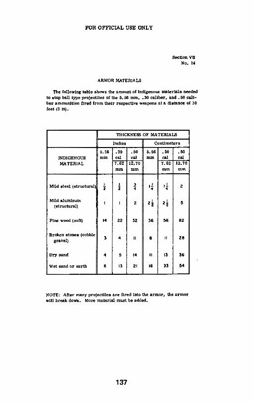
FOR OFFICIAL USE ONLY
ARMOR MATERIALS
Section Vn No. 14
The following table shows the amount of indigenous materials needed to stop ball type projectiles of the 5. 56 mm, • 30 caliber, and • 50 caliber ammunition fired from their respective weapons at a distance of 10 feet (3m).
THICKNESS OF MATERIALS
Inches Centimeters
5.56 .30 .50 5.56 .30 .so INDIGENOUS mm cal cal mm cal cal MATERIAL 7.62 12.70 7.62 12.70
mm mm mm mm
Mild steel (structural) I I 3 ,! ,! 2 2 2 4 4 4
Mild aluminum I I 2 2!. 2! 5
(structural) 2 2
Pine wood (soft) 14 22 32 36 56 82
Broken stones (cobble 3 4 II 8 II 28 gravel)
Dry sand 4 5 14 II 13 36
Wet sand or earth 6 13 21 16 33 54
NOTE: After many projectiles are fired into the armor, the armor will break down. More material must be added.
137

138
The M-14 Rlfle ............................................................... Order No. 015 .•..•.•..•... $7.95 The Beretta 92FIM9 ••••••..................••••••••.•....•••••••••••..... Order No. 129 ..•....•••... $9.95 The Colt .45 Auto Plstoi ............................................... Order No. 128 .•••.•••••••• $8.00 The Browning HI-Power Plstols ....•••••••.....•••••••••••..•.... Order No. 125 ••••••...•••• $9.00 UZI Submachlne-Gun No. 136 ••••••••••••• $7.00
Electronic Harassment................................................ No. 214 ..••••••••• $10.00 Construction of Secret Hiding Places ••.••••••••.•........... Order No. 436 .......•.•••• $9.00 FlghUng Back on the Job ••••••••••••••......•••••....•.........••.•• Order No. 200 ••••••••••• $10.00 Professional Homemade Salutes ..•••••••.••••.•.•••••••••••••• Order No. 542 .••..•••... $10.00 Take My Gun If You Dare •••.•.••••.•.••••••••••....•••••.••.••....... Order No. 551 ••..••.•••• $10.95
Science of Revolutionary ~~~rder No. 211 ............. $9.95 Improvised Weapons of the American Underground •.•.••••.•••.••••••••••••..••••••.............• Order No. 110 ••••••••••• $10.00 CIA Field Expedient Incendiary Manuai .•.••••....••.••..... Order No. 210 ••••••••••• $12.00 Improvised Shaped Charges ••••••••••••......•.••...............•• Order No. 250 •.••..••.•..• $6.95 CIA Explosives for Sabotage .•••••.••••..•••.•••••••••••.•.....•.. Order No. c-52 ••••••••••• $9.00 Poor Man's James Bond Vol.1 ...••.••..•••....••••••••.•..•••..• Order No. C-65 ••••••••• $21.95 Improvised MuniUons Black Books
Volume 1 ......••....••••••••••••.••••.••••••••••••••••.•.........•... Order No. 204 ....•..•••• $11.95 Volume 2 ••••..•.......•.•.•.•.•••.••••••••••••••••.••••••••••.•..•... Order No. 205 ••••••••••• $11.95 Volume 3 ............................................................. Order No. 225 •••....•... $18.95
fi'Jlit-~j---=j-) Vol. 1 AR-15 ModlflcaUon Manuai ..••••.•••••••••.....••.••••••• Order No. 061 ••••••.•••••• $7.95 Vol. 2 UZI ModlflcaUon Manuai .•..••••••••••••.•••••••••••••••••• Order No. 036 ••••••••.•••• $7.95 Vol. 3 Mac-10 Modification Manuai ............................. Order No. 010 ••••••••••••• $7.95 Vol. 4 Thompson SMG ModHicatlon Man ...•.............•• Order No. 027 .....•..•.•.• $7.95 Vol. 5 M1 Carbine Modification Manuai •.•..••••••••••••••••• Order No. 130 •••••..••..•. $7.95 Vol. 7 Bingham AK-22 ModlflcaUon Man ..•.•••••.••.•••••• Order No. 022 •.•..•.••••.• $7.95 Vol. 8 M14A1 & Mlnl-14 Mod Man •••••...•..•••...•••••••..•...•• Order No. 114 .••.••••••••• $7.95 Select Fire 10/22 •••••••••••..••.....•..•...••••••..•••••••••.•....•.••••••• Order No. 229 ........... $10.00 SelecUve Fire UZI ModlflcaUon Manual ••••••.•...••••...... Order No. 004 •••••.••••• $10.00
Add $4.95 shipping & handling to all orders.
To order have your credit card ready and call toll-free
1-800-852-4445 For Questions Calll-501-862-4984
Or send check or money order to: Desert Publication
P.O. Box 1751 Dept. BK205 El Dorado,AR 71731 U.S.A.

Send DESERT PubllcaUons
P.O. Box 1751 Dept. BK-205 El Dorado,AR 71731-1751 USA
501-862-2077
Add $4.95 to all orders for shipping
&handllng.