improving the performance of mppt on dc grid pv systems … · ... a converter based on power...
TRANSCRIPT

Abstract—The performance of photovoltaic (PV) system is
affected by temperature, solar insolation, solar panel
configuration and shading. In order to succeed maximum
efficiency, PV arrays should operate at their maximum power
point (MPP). Hence, the MPP tracking (MPPT) unit is
implemented among the PV energy conversion system to obtain
maximum power. In this study, incremental conductance (IC)
algorithm, the most commonly used algorithm in MPPT systems
for expectation-maximization, was analysed and an approach
towards eliminating ripple problems, improving speed to obtain
more power value, were maintained and duty cycle (Dk) value
was obtained from IC algorithm under changing PV panel
radiation conditions. In the end, it was evaluated alongside with
MATLAB simulation results.
Index Terms—Photovoltaic (PV) cell, incremental
conductance, maximum power point tracking (MPPT), boost
DC/DC converter.
I. INTRODUCTION
Recently, studies about PVs have focused on minimizing
the costs and maximizing the conversion efficiency. In MPP,
PV arrays generate the electric energy at maximum efficiency
and minimum losses. PV cells have variable current and
voltage characteristics and maximum power point depends on
solar irradiations and environment temperature. Because of
that a maximum power tracking control should be made
rapidly in varied temperature and solar insolation conditions.
Maximum power point trackers (MPPT) are improved to
catch maximum power level in different atmospherically
conditions [1]. So as to maximize the conversion efficiency
and captured energy from solar arrays, the PV system should
be operated at its maximum power point [2].
Although PV systems continue to occupy an important
position in electrical power technology, they have
disadvantages such as high cost and low conversion
efficiency.
This is largely because of the fact that output voltage and
current values vary in a nonlinear way depending on solar
radiation intensity, operating temperature and load current. In
this context, a converter based on power electronics was
needed so as to track variable voltage and current among
panel and load. In Fig. 1, I-V and P-V characteristics of a
solar module in the simulations are showed.
Manuscript received November 25, 2016; revised February 15, 2016.
Mehmet Ali Özçelik is with Gaziantep University, Vocational School of
Technical Sciences, Electric and Energy Department, Gaziantep, Turkey
(e-mail: [email protected]).
Ahmet Serdar Yılmaz is with Kahramanmaras Sutcu Imam University,
Engineering Faculty, Electrical-Electronics Eng. Department,
Kahramanmaras, Turkey (e-mail: [email protected]).
Fig. 1. Characteristics of solar module in the simulations (a) I-V Curve (b)
P-V Curve.
This is largely because of the fact that output voltage and
current values vary in a nonlinear way depending on solar
radiation intensity, operating temperature and load current. In
this context, a converter based on power electronics was
needed so as to track variable voltage and current among
panel and load. It is also important to track this intermediary
block where DC/DC converters are used. The triggering
frequency and range of switching Mosfet/IGBT in the
converter have a significant part to obtain maximum power
value.
The suitable converter type is a significant case for MPPT
design. Buck, boost and buck — boost types are mostly
preferred. Boost converters require more inductance than the
buck converter type, to achieve the same ripple of inductor
current. In these converter types, the effective current through
inductor is much less than that of buck converters. But, Buck
converters require larger and more expensive input capacitors
than Boost type to even the discontinuous input current from
solar array. Polarity of output voltage Buck/Boost type varies.
Hence, several converter types have been tested, suggested in
literature. In addition to well-known buck, boost and
buck-boost types, second generation converters such as
SEPIC [3], [4] and CUK [5], [6] are used in this field as well
as isolated flyback and forward [7] type converters used when
higher voltage conversion is required.
Furthermore, previous studies suggested various
controlling methods for MPPT design. Fuzzy logic [8] digital
signal processing (DSP) controllers [9], field programmable
gate array (FGPA) controllers [10], [11], parallel processing
topology [12] are some of the important methods and
controllers. In conventional PV, energy conversion systems
consist of serial connected solar panel, DC/DC converter and
battery (or DC load) as shown in Fig. 2.
Improving the Performance of MPPT on DC Grid PV
Systems by Modified Incremental Conductance Algorithm
Mehmet Ali Özçelik and Ahmet Serdar Yılmaz
Journal of Clean Energy Technologies, Vol. 5, No. 2, March 2017
114doi: 10.18178/jocet.2017.5.2.354

Fig. 2. Conventional PV energy conversion system.
In the literature, both converter design and MPPT
algorithms have been studied and presented so far. To reach
maximum power point faster, several algorithms such as
Perturbation and Observation (P&O) [13], [14], incremental
conductance [15], look-up table [16], [17], current control
loop [18] were proposed and applied.
This study focuses on an optimization of incremental
conductance algorithm. The chief advantage of this method is
that it doesn’t necessitate high ―complexity implementation‖
and that it requires less calculation parameters. The
disadvantage being that it generates ripple when it reaches the
maximum power point. Conventional IC algorithm is used
with constant iteration step size, it decision-making speed
increases in proportion to step size of error. But, higher error
step size reduces the efficiency of MPPT. This difficulty
causes the power losses and difficult the control actions.
Therefore, some calculation procedures of conventional IC
algorithm were modified.
II. PV SYSTEM
A. PV Cell Model
A photovoltaic cell is basically a PN semiconductor
junction diode that converts energy. As the sun light drops on
PV cells, photo-power acts like a forward diode on a large
surface. The current expression emerging as a result of the
sunlight hitting on the cell is given in 1.
SH
SLSPH
R
RIVRIV
TkA
q.III
1exp (1)
In this expression, photo-current, saturation current, load
resistance, series equivalent circuit resistance, parallel
equivalent circuit resistance, terminal voltage and load
current are denoted by IPH, IS, RL, RS, RSH, V and I, respectively.
The equivalent circuit diagram for a solar cell is shown in Fig.
3[19].
Fig. 3. Equivalent circuit diagram for solar cells.
Solar cells have a current source that are connected with a
parallel diode and resistance, to which is connected a serial
resistance. PV panels are built through series or parallel
connection of these solar cells. The relation between the
voltage of solar battery cells and current switched on the load
exposes I-V and P-V characteristics of the cell. These two
characteristics give important clues as to which conditions are
required in order for the power obtained from the panel to
reach its maximum level.
Obtaining maximum power and reaching highest efficiency
level in these panels is an importance research topic. Solar
panels act like a current source while, from a certain point
onward, they act like a voltage source. Current value that can
be obtained from a solar panel is fixed even in case of a short
circuit. This value is given along with the label of the panel. It
is necessary to obtain maximum power from PV panels in any
insolation condition. Maximum power point for PV systems
varies depending on atmospheric conditions, which are
ambient temperature and insolation amount. In general, PV
solar panels reach their maximum power point at around
2 5 °C . Two parallel connecting photovoltaic arrays are used
in this study. PV panel has electrical parameters are given in
Table I.
TABLE I: ELECTRICAL CHARACTERISTICS OF PV PANEL
Module specifications under STC Parameters
Open-circuit voltage (Voc) 64.2 V
Short-circuit current (Isc) 5.96 A
Voltage at Pmax (Vmp) 54.7 V
Current at Pmax (Imp) 5.58 A
Number of series-connected modules per string 5
Number of parallel string 66
B. Boost (Step Up) Type DC/DC Converter
Boost converter, as its name implies, is a structure that
boosts the voltage. Its simplified circuit diagram is shown in
Fig. 4. In PV systems, input voltage defined as VS is the
voltage in the panel while output voltage, defined as VO, is the
battery or load voltage.
Fig. 4. Circuit diagram for boost DC/DC converter.
Mosfet or IGBT is used as switching element. D (duty
cycle), which describes relative conduction time, equals to
switching element conduction time (ton) divided by signal
period which is the total conduction and cut-off time (T = Ton
+ Toff).
on on
on off
t tD
t t T
(2)
The conversion is performed in this converter as follows:
While switching element (S) turn on, PV structure injects
additional energy to inductance through driving current over
inductance (L). Then, switching element is cut off and reverse
Journal of Clean Energy Technologies, Vol. 5, No. 2, March 2017
115

current force in the inductance charges the capacity element
over the diode. The relationship between output voltage and
input voltage is as follows:
1
1S OV V
D
(3)
1pv
ID
I (4)
Boost structures are often preferred in stand-alone systems
and when panel voltage is lower than battery voltage.
III. ESSENTIALS OF INCREMENTAL CONDUCTANCE
ALGORITHM
This algorithm is also called hill climbing. The incremental
conductance algorithm is derived from the PV array power
together respect to voltage and setting the equal to zero. The
algorithm is given by the following Eq. (5).
( )0
dP d VI dII V
dV dV dV (5)
By accounting for the depended of the PV current on the
voltage, it is possible to express such a condition as follows
Eq. (6) [20].
0dI
I VdV
(6)
So that the validity of condition (5) is equivalent to follows
Eq. (7).
I dI
V dV (7)
Which means that left-hand side of Eq. (7) represents the
opposite of the PV array’s instantaneous conductance, as the
right-hand side represents its incremental conductance.
As a consequence, the method requires the application of a
repeated perturbation of the voltage value, until the next
condition occurs Eq. (8) [21].
1
1
k k k
k k k
I I I
V V V
(8)
where the subscript k and k-1 refer to two consecutive samples
of the PV voltage and current values. The conventional
algorithm (IC) is shown Fig. (5) [22].
At the maximum power point, the equations occurs in the
following Eq. (9a, 9b, 9c).
dI I
dV V ; 0
dP
dV
, at MPP (9a)
; 0dI I dP
dV V dV
, left of MPP (9b)
; 0dI I dP
dV V dV
, right of MPP (9c)
Fig. 5. Flowchart of the IC algorithm.
Equation (9a) is repeat of equation (7) for accordance,
equation (9b) and (9c) are used to determine the direction
where a perturbation must occur to move the operating point
toward the MPP, and the perturbation is repeated until
equation (9a) is pleased. When the maximum power point is
reached, the MPPT go on to work at this point up to a change
in current measured. This change in current will correlate to a
change in irradiance on the array. The increment step decide
how fast the MPP is tracked. Rapid tracking can be succeed
with large increments however, the system may not work
completely at the MPP and ripple around in place of it;
because of that there is a trade-off.
IV. PROPOSED INCREMENTAL CONDUCTANCE ALGORITHM
Fig. 6. Flowchart for proposed IC algorithm.
Journal of Clean Energy Technologies, Vol. 5, No. 2, March 2017
116
In the proposed algorithm, instead of fixed step coefficient
used to increase or decrease duty cycle, ∆P, denoting amount
of power change, is used in order to approach maximum
power point in proportion to an increase or decrease. In other
words, a parallel coefficient was provided for power change
to faster identify maximum power point. In case of no power
change, ∆P=0, no iteration was performed and oscillation was
minimized. In addition, At MPP, dI/dV+I/V = 0 and no
iteration is performed. Epsilon (Ɛ) is a number close to zero
but it is not zero. This Ɛ value can generate ripple under the
variable solar irradiation [23]. The ripple produces power loss.
So, if absolute value of dI/dV+I/V is smaller or equal than Ɛ,
the step of duty cycle will be reset (ΔP=0) which means that
D(k)=D(k-1) and ripple around maximum power point is
eliminated. The proposed algorithm is shown in Fig. 6.
The algorithm shown in Fig. 6 was designed in order to
prevent ripple emerging during attempts to identify maximum
power point of the incremental conductance algorithm and to
faster identify this point following significant power changes.
In this approach, ΔP = Pk – Pk-1 denotes power change. When
panel and DC converter duty cycle (Dk) is increased or
decreased in accordance with this power change, it is found
out in the simulation results that ripple is reduced and Dk at
maximum power point is identified sooner. In case of no
power change, ΔP = 0 or abs (dI/dV+I/V) ≤ Ɛ no iteration is
performed. In this case, ripple around maximum power point
under variable solar irradiation is eliminated and improving
the algorithm.
When power change increases, iteration coefficient
increases. Otherwise, iteration coefficient decreases. At left
side of MPP, If Dk increases, power increase and if Dk
decreases, power decreases too. Oppositely, at right side of
MPP, when Dk increases, power will decrease and when Dk
decreases, power will increase too. Therefore, when duty
cycle is changed, if there is an increasing in power, changing
on same way should be kept on (step which equal absolute
value ∆P should be added). If there is a decreasing in power,
changing should be continued on inverse way. (ΔP should be
subtracted). If Dk is > Dmax or if Dk < Dmin then D is to be
equaled to D(k-1) (Dmax and Dmin are duty cycle limits of the
DC/DC boost converter).
Fig. 7. Essential block of studied system with MPPT.
In Fig. (7), MPPT block structure where simulation is
performed is shown. MPPT is a power tracking system that
enables to obtain maximum power from PV panels. In MPPT
block, DC/DC converter is controlled by IC algorithm
through producing duty cycle. As a result of this, the
maximum power level from PV panel is reached.
V. COMPARISON OF CONVENTIONAL AND PROPOSED
INCREMENTAL CONDUCTANCE ALGORITHM
In simulations, two cases are applied to compare to both
algorithms. In the first case, outputs of PV panels are
considered when insolation decreases. In the second one,
same parameters are also tested when insolation increases or
decreases.
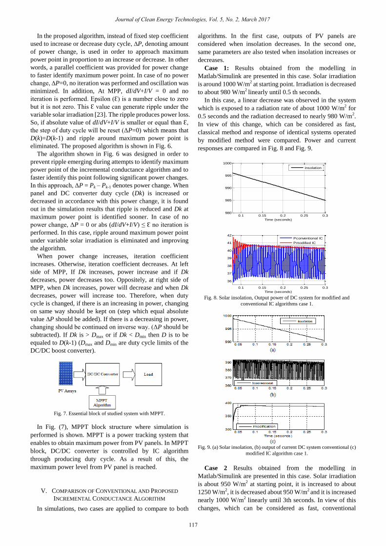
Case 1: Results obtained from the modelling in
Matlab/Simulink are presented in this case. Solar irradiation
is around 1000 W/m2 at starting point. Irradiation is decreased
to about 980 W/m2 linearly until 0.5 th seconds.
In this case, a linear decrease was observed in the system
which is exposed to a radiation rate of about 1000 W/m2 for
0.5 seconds and the radiation decreased to nearly 980 W/m2.
In view of this change, which can be considered as fast,
classical method and response of identical systems operated
by modified method were compared. Power and current
responses are compared in Fig. 8 and Fig. 9.
0.1 0.15 0.2 0.25 0.3980
985
990
995
1000
Time (seconds)
inso
latio
n
0.1 0.15 0.2 0.25 0.3
36
37
38
39
40
41
42
Time (seconds)
Pm
ean PV
(kW
)
insolation
Pconventional IC
Pmodified IC
Fig. 8. Solar insolation, Output power of DC system for modified and
conventional IC algorithms case 1.
Fig. 9. (a) Solar insolation, (b) output of current DC system conventional (c)
modified IC algorithm case 1.
Case 2 Results obtained from the modelling in
Matlab/Simulink are presented in this case. Solar irradiation
is about 950 W/m2 at starting point, it is increased to about
1250 W/m2, it is decreased about 950 W/m
2 and it is increased
nearly 1000 W/m2 linearly until 3th seconds. In view of this
changes, which can be considered as fast, conventional
Journal of Clean Energy Technologies, Vol. 5, No. 2, March 2017
117

algorithm and response of identical systems operated by
modified method were compared similar to Case I. Power and
current, responses are compared in Fig. 10 and Fig. 11.
Fig. 10. (a) Variable solar insolation, (b) Output power of DC system for
conventional and modified IC algorithm case 2.
TABLE II: OUTPUT POWERS UNDER VARIOUS SOLAR IRRADIANCE
W/m² Second Pmodified
(kW)
Pconventional
(kW)
Δ
946 2.0 44 37 7
1011 2.2 48 41 7
1090 2.4 52 43 9
1220 2.6 48 58 10
962 2.8 45 37 7
1010 3.0 47 40 7
In Fig. 10, it is demonstrated that in highly changing solar
irradiance conditions and in shorter time intervals, the
modified algorithm produces a higher value of power and less
oscillation under the changing conditions.
According to Table II ∆mean = 7.83 kW and when the
differences between output powers are considered, the rate in
the lowest irradiation case is 7 kW while in the highest case
there is a difference of 10 kW.
Fig. 11. Output current of DC system for conventional and modified IC
algorithms case 2.
It can be seen from the results of two cases, that modified
IC algorithm reaches to less time maximum power point than
conventional IC algorithm in this process. In addition,
modified IC algorithm produces less ripple than conventional
IC algorithm under rapidly changing solar insolation
conditions.
However, in conventional IC algorithm, both ripples occur
and maximum power point is attained slightly later.
Particularly, as shown in Fig. 8 and Fig. 10 power ripples are
to continue for a specific period of time. These ripples affect
total efficiency of the system negatively, too. Losses may be
encountered due to changing parameters as a result of ripples.
As these results suggest, the modified IC algorithm has a
good advantage with regards to ripple and improving
performance in the conventional IC algorithm. Ripple around
MPP is great difficulty of the conventional IC algorithm and
this proposed method arranges this problem and improving
efficiency with under this conditions.
VI. CONCLUSIONS
PV systems have a low efficiency in general. System
efficiency involves many equipment and parameters in the
system. Efficiency of a single solar cell may differ from that of
the panels comprising of these cells. Problems during
installation negatively affect panel efficiency. There are also
other factors such as panel angle, obstruction from high
buildings or cloudy weather conditions which cause total or
partial shadowing and thus decrease total efficiency. In
addition, software and hardware problems in MPPT decrease
efficiency. Switching losses in converter circuit may have
negative influence on total efficiency. Slow response rate of
the algorithm and, as stated in this study, occurrence of ripples
are also important problems under changing solar insolation
conditions. These factors force us to improve the algorithm.
This study focuses on improving algorithm and eliminating
ripple problems, and rapidly reaching more power value than
conventional IC algorithm in PV systems. Especially, when
variability increases as a result of factors such as partial
shadowing and cloudy weather, these ripples badly affect the
performance of the system. In order to increase the efficiency
of system, it is suggested that the algorithm should be
improved accordingly. It is also possible to suggest that
changes in the algorithm will bring out no difficulties in terms
of hardware, which makes it suitable for experimental
purposes. An improved IC algorithm is used to modulate the
duty cycle of the boost DC/DC converter, and thus, the
tracking speed increased. It is concluded that the proposed
algorithm shows better performance than conventional IC
algorithm under changing conditions and it reduces the power
losses.
REFERENCES
[1] G. A. M. Brito, L. Galotto, L. P. Sampaio, G. A. Melo, and C. A.
Canesin, ―Evaluation of the main MPPT techniques for photovoltaic
applications,‖ IEEE Transactions on Industrial Electronics, vol. 60,
no. 3, pp. 1156-1167, 2013.
[2] D. P. Hohm and M. E. Ropp, ―Comparative study of maximum point
tracking algorithms using an experimental, programmable, maximum
Powerpoint tracking test bed,‖ in Proc. 28th IEEE Photovoltaic Spec.
Conf., 2000, pp. 1699-1702.
[3] M. Veerachary, ―Power tracking for non-linear PV sources with
coupled inductor SEPIC converter,‖ IEEE Trans. Aerospaceand
Electronic Systems, vol. 41, pp. 1019-1029, 2005.
[4] S. J. Chiang, S. Hsin-Jang, and C. Ming-Chieh, ―Modeling and control
of PV charger system with SEPIC converter,‖ IEEE Trans. Industrial
Electronics, vol. 56, pp. 4344-4353, 2009.
[5] D. C. Raiwan and C. V. Nayar, ―Analysis and design of a solar charge
controller using Cuk converter,‖ in Proc. Aust. Univ. Power Eng.
Conf., 2007, pp. 1-6.
[6] A. Safari, ―Simulation and hardware implementation of incremental
conductance MPPT with direct control method using Cuk converter,‖
Journal of Clean Energy Technologies, Vol. 5, No. 2, March 2017
118

IEEE Trans Industrial Electronics, vol. 58, no. 4, pp. 1154-1161,
2011.
[7] B. J. D. Vermulst, G. E. Wijnands, and J. L. Duarte, ―Isolated
high-efficiency DC/DC converter for photovoltaic applications,‖ in
Proc. 38th Annual Conf. on IEEE IAS, 2012, pp. 25-28.
[8] I. H. Altas and A. M. Sharaf, ―A Novel maximum power fuzzy logic
controller for photovoltaic solar energy systems,‖ Renewable Energy,
vol. 33, no. 3, pp. 388-399, 2008.
[9] C. Hua, J. Lin, and C. Shen, ―Implementation of a DSP-Controlled
photovoltaic system with peak power tracking,‖ IEEE Trans Industrial
Electronics, vol. 45, pp. 99-107, 1998.
[10] E. Koutroulis, K. Kalaitzakis, and V. Tzitzilonis, ―Development of an
FPGA-based system for real-time simulation,‖ Microelectronics
Journal, vol. 40, pp. 1094-1102, 2009.
[11] A. Mellit, H. Rezzouk, A. Messai, and B. Medjahed, ―FPGA-based real
time implementation of MPPT-controller for photovoltaic systems,‖
Renewable Energy, vol. 36, pp. 1652-1661, 2011.
[12] M. O. Badawy, A. S. Yilmaz, Y. Sozer, and I. Husein, ―Parallel power
processing topology for solar PV applications,‖ IEEE Trans. Industry
Applications, vol. 50, no. 2, pp. 1245-1255, 2014.
[13] V. Salas et al., ―Evaluation of a new maximum power point tracker
(MPPT) applied to the photovoltaic stand alone systems,‖ Solar
Energy Materials and Solar Cells, vol. 87, pp. 807-815, 2005.
[14] T. Esram and P. L. Chapman, ―Comparison of photovoltaic array
maximum power point tracking techniques,‖ IEEE Trans on Energy
Conversion, vol. 22, no. 2, pp. 439-449, 2007.
[15] M. G. Wanzeller, R. N. C. Alves, and W. A. Santos, ―Current control
loop for tracking of maximum power point supplied for photovoltaic
array,‖ IEEE Trans. on Instrumentation and Measurement, vol. 53, pp.
1304-1310, 2004.
[16] N. Onat, ―Recent developments in maximum power point tracking
technologies for photovoltaic systems,‖ International Journal of
Photo Energy, 2010.
[17] S. T. Kok and M. Saad, ―Modified incremental conductance algorithm
for photovoltaic system under partial shading conditions and load
variation,‖ IEEE Transactions on Industrial Electronics, vol. 61, no.
10, 2014.
[18] B. Burger and D. Kranzer, ―Extreme high efficiency PV power
converters,‖ in Proc. 13th European Conference Power Electronics
and Applications, September 2009, pp. 1-13.
[19] M. A. Özçelik and A. S. Yılmaz, ―Effect of maximum power point
tracking in photovoltaic systems and its improving and its application
of wireless energy transmission,‖ in Proc. 1st Journal Conference on
Clean Energy and Technologies, Paris, France, 2014.
[20] A. E. Mohamed and Z. Zheng, ―MPPT techniques for photovoltaic
applications,‖ Renewable and Sustainable Energy Reviews, pp.
793-813, 2013.
[21] F. Nicola, P. Giovanni, S. Giovanni, and V. Massimo, ―Power
electronics and control techniques for maximum energy harvesting in
photovoltaic systems,‖ Industrial Electronics Magazine, vol. 7, issue 3,
pp. 71-74, 2013,
[22] M. A. Abdourraziq and M. Maaroufi, ―A new variable step size INC
MPPT method for PV systems,‖ in Proc. IEEE Multimedia Computing
and Systems (ICMCS) International Conference, 2014.
[23] I. Kashif and S. Zainal, ―A review of maximum power point tracking
techniques of PV system for uniform insolation and partial shading
condition,‖ Renewable and Sustainable Energy Reviews, pp. 475-488,
2013.
Mehmet Ali Özçelik was born in İskenderun, Turkey. He received the B.E.,
M.E., and PhD degrees in electrical education, Marmara University, Istanbul
and in electrical & electronics engineering, Sutcu Imam University,
Kahramanmaras, Turkey, in 1999, 2006, 2015 respectively. He is currently
an Asst. Prof. at the Department of Electric and Energy, Gaziantep
University, Turkey. His field of interest includes PV energy conversion
systems and MPPT algorithms.
Ahmet Serdar Yılmaz was born in Kahramanmaras, Turkey. He received
the B.E., M.E., and Dr. Eng. degrees in electrical & electronics engineering,
Sakarya University, Turkey, 1994, 1997 and 2002, respectively. In 1995, he
joined the Department of Electrical and Electronics Engineering, Sakarya
University, as a research assistant then became an assistant professor and an
associate professor in 2003 and 2011, respectively. He is a currently an
associate professor at the Department of Electrical and Electronics
Engineering, Sutcu İmam University, Kahramanmaras, Turkey. His current
research interests include power quality, power systems, wind and solar
energy conversion systems. He is member of the IEEE.
Journal of Clean Energy Technologies, Vol. 5, No. 2, March 2017
119