improving the performance of mems imu/gps pos systems for land
TRANSCRIPT

IMPROVING THE PERFORMANCE OF MEMS IMU/GPS POS SYSTEMS FOR LAND BASED MMS UTILIZING TIGHTLY COUPLED INTEGRATION AND ODOMETER
Y-W. Huang,a,K-W. Chiangb
Department of Geomatics, National Cheng Kung University, 1 University Dr, Tainan, 70101, Taiwan
a [email protected], [email protected]
Commission V, ICWG V/1
KEY WORDS: INS, GPS, Tightly coupled, Kalman filter, Odometer ABSTRACT: Integrated GPS/INS systems provide an enhanced navigation system that has superior performance in comparison with either system operating in stand-alone mode as it can overcome each of their limitations. The high cost and government regulations prevent the wider inclusion of high quality IMUs to augment GPS as a commercialized navigation system in many navigation applications. The progress in MEMS technology enables complete inertial units on a chip, composed of multiple integrated MEMS accelerometers and gyroscopes. In addition to their compact and portable size, the price of MEMS based is far less than those high quality IMUs as well, however, due to the lightweight and fabrication process, MEMS sensors have large bias instability and noise, which consequently affect the obtained accuracy from MEMS-based IMUs. Many research works have been conducted to improve the performance of low cost MEMS-based INS/GPS integrated systems. In this study, LC and TC integration are provided to analyse the performance of these two integration schemes for land based MMS applications.
INTRODUCTION
The early development of mobile mapping system (MMS) was restricted to applications that permitted the determination of the elements of exterior orientation from existing ground control. In the early nineties, advances in satellite and inertial technology made it possible to think about mobile mapping in a different way. Instead of using ground control points as references for orienting the images in space, the trajectory and attitude of the imager platform could now be determined directly. Direct geo-referencing is the determination of time-variable position and orientation parameters for a mobile digital imager (El-Sheimy, 1996). The most common technologies used for this purpose today are satellite positioning using the Global Positioning System (GPS) and inertial navigation using an Inertial Measuring Unit (IMU). Although either technology used along could in principle determine both position and orientation, they are usually integrated in such a way that the IMU is the main orientation sensor, while the GPS receiver is the main position sensor. The orientation accuracy of an IMU is largely determined by the gyro drift rates, typically described by a bias (constant drift rate), the short term bias stability, and the angle random walk.
In principle, an IMU refers to a set of inertial sensors including three gyroscopes and accelerometers and it provides compensated raw measurements including velocities changes (delta-Vs) and orientation changes (delta- θ s) along three directions of its body frame. Those who require real time navigation solutions with the use of an IMU require an external computer that has inertial navigation mechanization algorithms. On the other hand, an Inertial Navigation System (INS) usually refers to an IMU combining with an onboard computer thus it can provide navigation solutions in the chosen navigation frame directly in real time, in addition, it also provides compensated raw measurements. Therefore, the main distinction between an IMU and INS is that the former along can’t provide real time navigation solutions, it only provides compensated inertial
measurements when an INS along can provide real time navigation solutions as well as compensated inertial measurements (Titterton, 2004). Kalman filter (KF) approach has been widely recognized as a common optimal estimation tool to process INS/GPS integration data. However, there are limitations, which have been indicated by Chiang (2004). The major inadequacy related to the utilization of KF for INS/GPS integration is the necessity to have a predefined accurate stochastic model for each of the sensor errors. Furthermore, prior information about the covariance values of both inertial and GPS data as well as the statistical properties (i.e. the variance and the correlation time) of each sensor system has to be accurately known. Furthermore, for INS/GPS integration applications (where the process and measurement models are nonlinear), Extended Kalman filter (EKF) operates under the assumption that the state variables behave as Gaussian Random Variables. Naturally, EKF may also work for nonlinear dynamic systems with non-Gaussian distributions, except for heavily skewed nonlinear dynamic systems, where EKF may experience problems. The loosely coupled (LC) system is commonly used as an INS/GPS integration approach due to its simplicity to derive navigation information. In the LC integration, there are two individual filters: one to process the GPS measurements, and the other one to perform the INS/GPS integration. The filter used for integration is the main one in the configuration and uses the output of the INS mechanization to estimate the states along the trajectory. The output of the first filter is then used to update the INS. In other words, position and velocity update modes are the standard procedures to provide measurement updates with the aiding information provided by GPS. However, the limitation of the LC integration is that the GPS KF would not provide position and velocity solutions as position and velocity updates for the INS KF if less than four satellites were tracked. Another type of integration is known as tightly coupled (TC), which combines the two systems at the measurement level. In the TC integration, there is only one KF,
which processes the raw IMU measurements for navigation. In the urban area, since there is usually less than four GPS satellites can be tracked for the LC to provide updates to the INS KF, the INS errors will grow as a function of time during GPS signal outages. However, the GPS receiver can still receive at least one to three satellite signals. Therefore, tightly coupled integration should be beneficial in such poor GPS signal reception environments because the measurement updates can be provided even if there are less than four satellites in the sky. Additionally, vehicle body velocities provided by the odometer are used to minimize the POS errors during GPS signal gaps. Hence, utilizing TC for INS/GPS integration should be a better approach to derive trajectories of a land based MMS applications in the urban area.
LOOSELY AND TIGHTLY COUPLED INTEGRATION
The most common integration scheme used today is loosely coupled (LC) integration. The typical LC integration architecture is shown as Figure 1. The position and velocity of the estimated by the GPS KF is processed in the navigation Kalman filter to aid the INS, which is known as decentralized or cascaded filtering as well. This kind of integration has the benefit of a simpler architecture which is easy to utilize in navigation systems. However, the errors in the position and velocity information provided by the GPS KF are time-correlated, which can cause a degradation in performance or even instability of the navigation Kalman filter, if these correlations are not considered by some means. In the case of incomplete constellations, i.e. less than four satellites in view, the output of the GPS receiver has to be ignored completely, leaving the INS unaided.
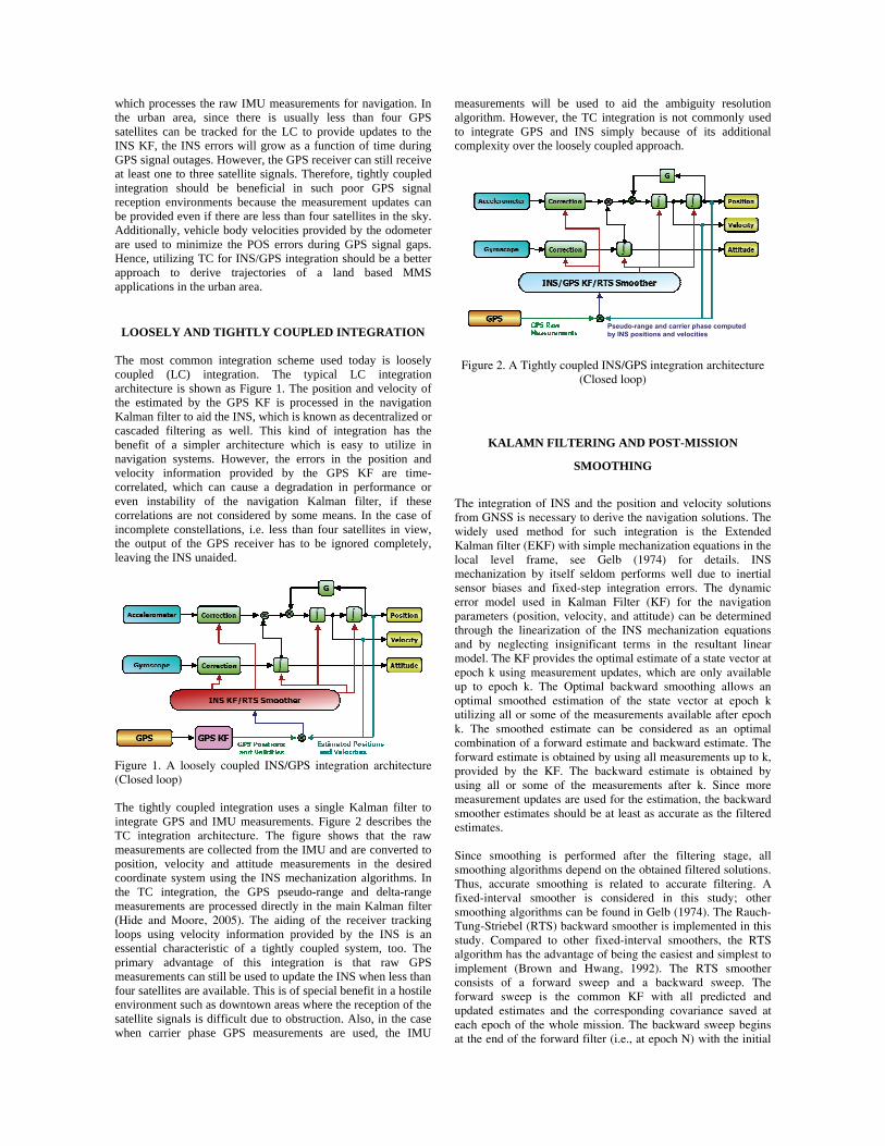
Figure 1. A loosely coupled INS/GPS integration architecture (Closed loop) The tightly coupled integration uses a single Kalman filter to integrate GPS and IMU measurements. Figure 2 describes the TC integration architecture. The figure shows that the raw measurements are collected from the IMU and are converted to position, velocity and attitude measurements in the desired coordinate system using the INS mechanization algorithms. In the TC integration, the GPS pseudo-range and delta-range measurements are processed directly in the main Kalman filter (Hide and Moore, 2005). The aiding of the receiver tracking loops using velocity information provided by the INS is an essential characteristic of a tightly coupled system, too. The primary advantage of this integration is that raw GPS measurements can still be used to update the INS when less than four satellites are available. This is of special benefit in a hostile environment such as downtown areas where the reception of the satellite signals is difficult due to obstruction. Also, in the case when carrier phase GPS measurements are used, the IMU
measurements will be used to aid the ambiguity resolution algorithm. However, the TC integration is not commonly used to integrate GPS and INS simply because of its additional complexity over the loosely coupled approach.
Figure 2. A Tightly coupled INS/GPS integration architecture (Closed loop)
KALAMN FILTERING AND POST-MISSION
SMOOTHING
The integration of INS and the position and velocity solutions from GNSS is necessary to derive the navigation solutions. The widely used method for such integration is the Extended Kalman filter (EKF) with simple mechanization equations in the local level frame, see Gelb (1974) for details. INS mechanization by itself seldom performs well due to inertial sensor biases and fixed-step integration errors. The dynamic error model used in Kalman Filter (KF) for the navigation parameters (position, velocity, and attitude) can be determined through the linearization of the INS mechanization equations and by neglecting insignificant terms in the resultant linear model. The KF provides the optimal estimate of a state vector at epoch k using measurement updates, which are only available up to epoch k. The Optimal backward smoothing allows an optimal smoothed estimation of the state vector at epoch k utilizing all or some of the measurements available after epoch k. The smoothed estimate can be considered as an optimal combination of a forward estimate and backward estimate. The forward estimate is obtained by using all measurements up to k, provided by the KF. The backward estimate is obtained by using all or some of the measurements after k. Since more measurement updates are used for the estimation, the backward smoother estimates should be at least as accurate as the filtered estimates. Since smoothing is performed after the filtering stage, all smoothing algorithms depend on the obtained filtered solutions. Thus, accurate smoothing is related to accurate filtering. A fixed-interval smoother is considered in this study; other smoothing algorithms can be found in Gelb (1974). The Rauch-Tung-Striebel (RTS) backward smoother is implemented in this study. Compared to other fixed-interval smoothers, the RTS algorithm has the advantage of being the easiest and simplest to implement (Brown and Hwang, 1992). The RTS smoother consists of a forward sweep and a backward sweep. The forward sweep is the common KF with all predicted and updated estimates and the corresponding covariance saved at each epoch of the whole mission. The backward sweep begins at the end of the forward filter (i.e., at epoch N) with the initial
Pseudo-range and carrier phase computed by INS positions and velocities
conditions of , ,ˆˆ sN N N Nxx = and , ,
sN N N NP P= . The RTS
algorithms can be found in details in Brown and Hwang (1992).
The RTS smoothed estimate at any epoch k is computed as a linear combination of the filtered estimate at that epoch and the smoothed estimate at next epoch k+1. Thus, the RTS smoothed estimate can be considered as an updated forward filtered solution]. The computation of the smoothed estimate at each epoch requires the storage of the KF predicted and updated (filtered) estimates and their corresponding covariance at each epoch. This is the case in INS/DGNSS integrated solutions, when uninterrupted data streams are available. In case of DGNSS outages, only predicted estimates and covariance are available. A conceptual plot of the impact of the RTS smoother on the positioning error in case of a GNSS outage is given in figure 3. As shown in the figure, a post-mission RTS smoother can remove most of the residual errors of KF.
Beginning of GPS outage
End of GPS outage
Residual errors of Kalman filter
Residual errors of smoothing
Improvement achieved by smoothing
Improvement needed to be achieved
Figure 3: Impact of RTS smoother on the positioning error during GNSS outage.
=
FIELD TEST RESULT
Figure 4. Typical views in the first field test in Tainan
To analyze the performance of tight integration combined with RTS smoothing for GPS and low cost INS for land based MMS, two field tests were conducted in two cities, Tainan and Kaohsiung city where the performance of the proposed methods of this study in the different scenarios of test environment could be tested. In the Tainan city trial, two scenarios were considered, the open areas which GPS measurements were always available and the area that high buildings besides the road that might obstacle some GPS signal. The typical views of the test environment in the Tainan city was shown as figure 4. In the Kaohsiung trial, an extreme difficult environment that the GPS signals may be fully blocked for a long distance (over one kilometer) in a few minutes such as a path that just under the
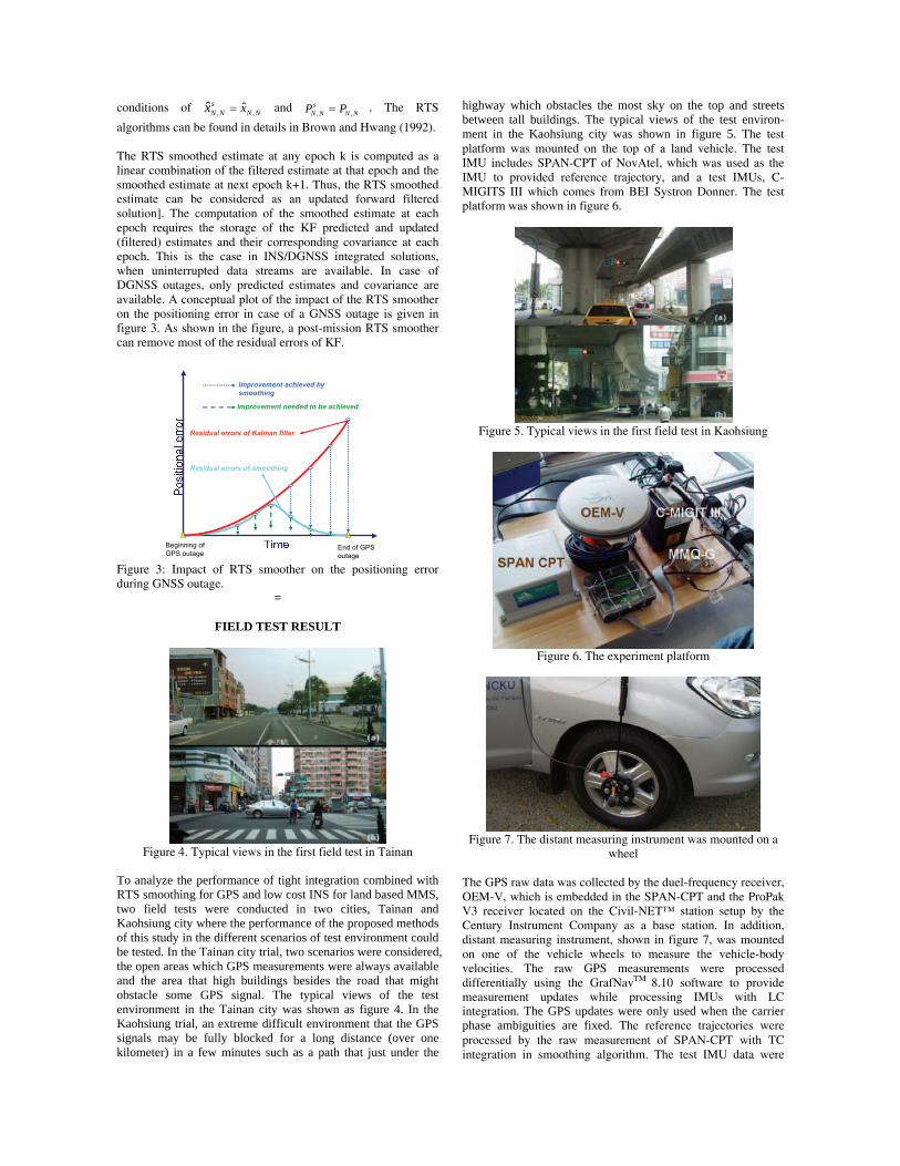
highway which obstacles the most sky on the top and streets between tall buildings. The typical views of the test environ-ment in the Kaohsiung city was shown in figure 5. The test platform was mounted on the top of a land vehicle. The test IMU includes SPAN-CPT of NovAtel, which was used as the IMU to provided reference trajectory, and a test IMUs, C-MIGITS III which comes from BEI Systron Donner. The test platform was shown in figure 6.
Figure 5. Typical views in the first field test in Kaohsiung
Figure 6. The experiment platform
Figure 7. The distant measuring instrument was mounted on a
wheel The GPS raw data was collected by the duel-frequency receiver, OEM-V, which is embedded in the SPAN-CPT and the ProPak V3 receiver located on the Civil-NET™ station setup by the Century Instrument Company as a base station. In addition, distant measuring instrument, shown in figure 7, was mounted on one of the vehicle wheels to measure the vehicle-body velocities. The raw GPS measurements were processed differentially using the GrafNavTM 8.10 software to provide measurement updates while processing IMUs with LC integration. The GPS updates were only used when the carrier phase ambiguities are fixed. The reference trajectories were processed by the raw measurement of SPAN-CPT with TC integration in smoothing algorithm. The test IMU data were

processed by a low cost IMU, C-MIGITSTM III (~30k) with raw GPS measurement collected by embedded receiver of SPAN-CPT. The lever arms between GPS and IMUs were measured befor the test. In addtions, all trjectories in LC or TC integrations were processed and smoothed by a commercial IMU/GPS processing software, Inertial Explore 8.10. The position and attitude errors are then computed by the difference between the test IMU trajectory and the reference IMU trajectory. Test in Tainan City The field test route of Tainan city was shown as figure 8. A five-minute static alignment process was applied at the beginning of the test to derive the initial attitude of sensors. The field test took about 50 minutes. In this field test, the test vehicle was first going around in an open sky area for about 30 minute then driving into the blocks that GPS outages might occur in the remain test period. There were less than 4 satellites available in the sky 25% of the time, which means that position and velocity updates were not provided by GPS for LC integration during the third field test.
Figure 8. Test trajectory 1
Figure 9. Position errors of C-MIGITS III on the field test
(Using odometer) The comparison between LC and LC integration with odometer measurement updates of C-MIGITS III on position and heading errors were shown on figure 9 and 10, The comparison between LC and TC integration of C-MIGITS III were shown on figure 11 and 12. As shown on figures, the POS has reliable accuracies in the open sky area. However, while passing the area that GPS signals were blocked by buildings, the position accuracy degrades quickly since there are very few satellite signals
available in the sky. Hence, the measurement updates for LC and TC are not provided so the position errors were estimated in prediction mode. In this case, extra updates provided by an odometer, which is able to measure vehicle-body velocities seamlessly, could be a update source of the Kalman filtering. A comparison among the positioning and orientation performance of the tightly coupled smoothed solution, loosely coupled integration with odometer smoothed solution and loosely coupled smoothed solution was shown in table 1 As shown in table 1, there are huge enhancements in both positioning and orientation accuracy. The root mean square of the C-MIGITS III of the horizontal position is reduced to less than 1m which is closing the requirement of land-based MMS application.
Figure 10. Attitude errors of C-MIGITS III on the field test
(Using odometer)
Figure 11. Position errors of C-MIGITS III on the field test (TC
and LC integration) Test in the extreme difficult environment in Kaohsiung The second field test route held in Kaohsiung city was shown as figure 13. In the beginning of the test, an INS initialization process was applied to acquire the initial attitude of sensors. This field test took about 25 minutes and longest GPS outage duration occurred from the 4th minute to the 11th minute of the test. There were less than 4 satellites available in the sky 50% of the time so that measurement updates were not available from GPS for LC integration during the field test. The comparison between LC and LC integration with odometer aiding of C-MIGITS III on position and heading errors were shown on figure 14 and 15, The comparison between LC and LC integration of C-MIGITS III were shown on figure 16 and 17. As shown on figures, while passing the paths under the freeway, the position accuracy degrades quickly if utilizing LC integration to compute navigation parameters. As shown in the figures of position error comparison, while the extra velocity update provided by an odometers was utilized in the LC
0 500 1000 1500 2000 2500-8-6-4-202
Position Error of C-MIGIT III
Eas
t (m
)
0 500 1000 1500 2000 2500-202468
Nor
th (
m)
0 500 1000 1500 2000 2500-202468
Hei
ght
(m)
GPS Time (sec), t0=287639
LCTC
0 500 1000 1500 2000 2500-2
-1
0
1Attitude Error of C-MIGIT III
Rol
l (de
g)
0 500 1000 1500 2000 2500-2
-1
0
1
Pitc
h (d
eg)
0 500 1000 1500 2000 2500-2
-1
0
1
Hea
dind
(de
g)
GPS Time (sec), t0=287639
LCLC+DMI
0 500 1000 1500 2000 2500-8-6-4-202
Position Error of C-MIGIT III
Eas
t (m
)
0 500 1000 1500 2000 2500-202468
Nor
th (
m)
0 500 1000 1500 2000 2500-202468
Hei
ght
(m)
GPS Time (sec), t0=287639
LCLC+DMI
0 500 1000 1500 2000 2500
0
200
400
600
800
1000
1200
1400
1600
1800
2000
Test Trjectory(λ
0= 22o58'57.7419", φ
0= 120o9'25.2411", h
0= 23.1952)
ref. IMU/GPSDGPS

integration or the TC integration was applied, position errors may not growing as quickly as the original LC integration in long GPS outages. Furthermore, during most periods where there are 4 or more satellites available, the DOP value was large due to poor satellite geometry. On the other hand, the reflections of the signals in the downtown area have degraded the accuracy of GPS position and velocity solutions. In this case, the qualities of measurement updates for neither LC nor TC integration cannot be garneted. Therefore error states estimated by KF in updated mode were not able to improve the accuracies of the navigation solutions.
Figure 12. Attitude errors of C-MIGITS III on the field test (TC
and LC integration)
C-MIGITS III
RMS value (m) (deg)
Improvement (%) LC LC+DMI
East 1.082 0.738 31.82
North 0.512 0.302 41.02
Up 0.471 0.293 37.89
Roll 0.067 0.055 17.81
Pitch 0.044 0.020 55.58
Heading 0.399 0.176 55.73
RMS value (m) (deg)
Improvement (%) LC TC
East 1.082 0.498 54.02
North 0.512 0.338 33.90
Up 0.471 0.357 24.23
Roll 0.067 0.059 11.53
Pitch 0.044 0.016 62.87
Heading 0.399 0.185 53.60
Table 1. The enhancement in positioning and orientation
accuracy A comparison among the positioning and orientation performance of the tightly coupled smoothed solution, loosely coupled integration with odometer smoothed solution and loosely coupled smoothed solution was shown in table 2 As shown in Table 2, there are enhancements in the all directions of position accuracy of C-MIGITS III utilized both TC integration and odometer updates. The attitude accuracies after applying the methods purposed in the article did not performed better than the original LC integration since the attitude errors remained in an acceptable range during GPS outages.
Figure 13. Test trajectory 2
Figure 14. Position errors of C-MIGITS III on the field test (Using odometer)
Figure 15. Attitude errors of C-MIGITS III on the field test (Using odometer)
Figure 16. Position errors of C-MIGITS III on the field test (TC
and LC integration)
0 200 400 600 800 1000 1200 1400 1600-0.4-0.2
00.20.40.60.8
Attitude Error of C-MIGIT III
Rol
l (de
g) LCLC+DMI
0 200 400 600 800 1000 1200 1400 1600-0.4-0.2
00.20.40.60.8
Pitc
h (d
eg)
0 200 400 600 800 1000 1200 1400 1600-0.4-0.2
00.20.40.60.8
Hea
dind
(de
g)
GPS Time (sec), t0=192640
0 200 400 600 800 1000 1200 1400 1600
0
5
10
15Position Error of C-MIGIT III
Eas
t (m
)
0 200 400 600 800 1000 1200 1400 1600-5
0
5
10
Nor
th (
m)
0 200 400 600 800 1000 1200 1400 1600-15
-10
-5
0H
eigh
t (m
)
GPS Time (sec), t0=192640
LCLC+DMI
0 500 1000 1500 2000 2500-2
-1
0
1Attitude Error of C-MIGIT III
Rol
l (de
g)
LCTC
0 500 1000 1500 2000 2500-2
-1
0
1
Pitc
h (d
eg)
0 500 1000 1500 2000 2500-2
-1
0
1
Hea
dind
(de
g)
GPS Time (sec), t0=287639
0 200 400 600 800 1000 1200 1400 1600-5
05
10
15Position Error of C-MIGIT III
Eas
t (m
)
0 200 400 600 800 1000 1200 1400 1600-505
1015
Nor
th (
m)
0 200 400 600 800 1000 1200 1400 1600-15-10-505
Hei
ght
(m)
GPS Time (sec), t0=192640
LCTC
0 1000 2000 3000 4000 5000
-1500
-1000
-500
0
500
1000
1500
2000
Test Trjectory(λ
0= 22o35'7.6974", φ
0= 120o21'18.0909", h
0= 27.3327)
ref. IMU/GPSDGPS
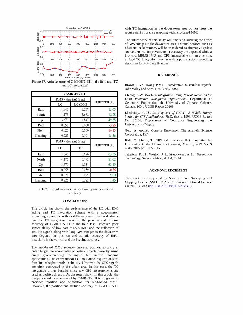
Figure 17. Attitude errors of C-MIGITS III on the field test (TC
and LC integration)
C-MIGITS III
RMS value (m) (deg)
Improvement (%) LC LC+DMI
East 1.846 1.557 15.65
North 4.175 3.662 12.28
Up 3.671 1.847 49.68
Roll 0.058 0.060 -3.26
Pitch 0.026 0.030 -16.15
Heading 0.225 0.191 15.36
RMS value (m) (deg)
Improvement (%) LC TC
East 1.846 0.676 63.36
North 4.175 0.792 81.02
Up 3.671 1.351 63.19
Roll 0.058 0.059 -0.86
Pitch 0.026 0.025 5.00
Heading 0.225 0.222 1.46
Table 2. The enhancement in positioning and orientation
accuracy
CONCLUSIONS This article has shown the performance of the LC with DMI aiding and TC integration scheme with a post-mission smoothing algorithm in three different areas. The result shows that the TC integration enhanced the position and heading accuracy of C-MIGITS III in the field test. However, poor sensor ability of low cost MEMS IMU and the reflection of satellite signals along with long GPS outages in the downtown area degrade the position and attitude accuracy of IMU, especially in the vertical and the heading accuracy. The land-based MMS requires cm-level position accuracy in order to get the coordinates of feature objects correctly using direct geo-referencing techniques for precise mapping applications. The conventional LC integration requires at least four line-of-sight signals in the sky. However, the GPS signals are often obstructed in the urban area. In this case, the TC integration brings benefits since raw GPS measurements are used as updates directly. As the result shown in this article, the navigation solution computed by C-MIGITS III is suggested to provided position and orientation for land-based MMS. However, the position and attitude accuracy of C-MIGITS III
with TC integration in the down town area do not meet the requirement of precise mapping with land-based MMS. The future work of this study will focus on bridging the effect of GPS outages in the downtown area. External sensors, such as odometer or barometer, will be considered as alternative update sources. Hence, improvements in accuracy are expected while a low cost MEMS IMU and GPS integrated with more sensors utilized TC integration scheme with a post-mission smoothing algorithm for MMS applications.
REFERENCE
Brown R.G.; Hwang P.Y.C. Introduction to random signals. John Wiley and Sons. New York. 1992.
Chiang, K.W. INS/GPS Integration Using Neural Networks for Land Vehicular Navigation Applications. Department of Geomatics Engineering, the University of Calgary, Calgary, Canada, 2004; UCGE Report 20209.
El-Sheimy, N. The Development of VISAT - A Mobile Survey System for GIS Applications, Ph.D. thesis, 1996; UCGE Report No. 20101, Department of Geomatics Engineering, the University of Calgary.
Gelb, A. Applied Optimal Estimation. The Analytic Science Corporation, 1974.
Hide, C.; Moore, T.; GPS and Low Cost INS Integration for Positioning in the Urban Environment, Proc. of ION GNSS 2005; 2005 pp.1007-1015
Titterton, D. H.; Weston, J. L. Strapdown Inertial Navigation Technology, Second edition, AIAA, 2004.
ACKNOWLEDGEMENT This work was supported by National Land Surveying and Mapping Center (NSLC 97-28), Taiwan and National Science Council, Taiwan (NSC 98-2221-E006-223-MY2).
0 200 400 600 800 1000 1200 1400 1600-0.5
0
0.5
Attitude Error of C-MIGIT III
Rol
l (de
g)
LCTC
0 200 400 600 800 1000 1200 1400 1600-0.5
0
0.5
Pitc
h (d
eg)
0 200 400 600 800 1000 1200 1400 1600-0.5
0
0.5
Hea
dind
(de
g)
GPS Time (sec), t0=192640