improving heat transfer in a triplex tube heat exchanger
TRANSCRIPT

Scientia Iranica B (2020) 27(1), 239{251
Sharif University of TechnologyScientia Iranica
Transactions B: Mechanical Engineeringhttp://scientiairanica.sharif.edu
Improving heat transfer in a triplex tube heatexchanger containing phase-change materials bymodi�cations of length and position of �ns
M.M. Hosseini and A.B. Rahimi�
Faculty of Engineering, Ferdowsi University of Mashhad, Mashhad, Iran.
Received 18 November 2017; received in revised form 18 August 2018; accepted 3 December 2018
KEYWORDSPhase changematerial;Triplex tube;Heat transferenhancement;Fins arrangements.
Abstract. Heat thermal energy storage is a technique used to improve thermal e�ciencyby reducing the discrepancy between energy demand and supply. Latent heat thermalenergy storage as a kind of the thermal energy storage method has drawn considerableattention from researchers due to its high thermal energy density and a constant operatingtemperature. This study numerically investigated the melting process in a triplex tube heatexchanger containing Phase-Change Material (PCM) RT82. A two-dimensional numericalmodel was generated using the Ansys Fluent 16 software program to simulate the meltingprocess. In this study, conduction and natural convection were considered. Certainarrangements of rectangular �ns including lengths and positions were selected accordingto heat distribution, while the total area of �ns was kept constant. This new strategywas done to improve heat transfer in PCM, which would result in decreasing its meltingtime. The selected optimized model in this article reduced the melting time to 28.4% incomparison with the model in [Mat, S., Al-Abidi, A.A., Sopian, K., et al. \Enhance eattransfer for PCM melting in triplex tube with internal-external �ns", Energy Conversionand Management, 74, pp. 223{236 (2013)]. Numerical results were in agreement with thenumerical and experimental results of the above-mentioned reference, thus verifying thevalidity of the obtained results.
© 2020 Sharif University of Technology. All rights reserved.
1. Introduction
Most clean kinds of energy are naturally unsteady andrequire facilities to store them. For instance, solarenergy is an intermittent energy source that causesmismatch between energy supply and demand for solarthermal energy applications. In order to solve this
*. Corresponding author.E-mail addresses: mohammad [email protected] (M.M.Hosseini); [email protected] (A.B. Rahimi)
doi: 10.24200/sci.2018.5604.1369
issue, Latent Heat Thermal Energy Storage (LHTES)is employed to improve the e�ciency of solar energysystems. From an environmental viewpoint on a globalscale, LHTES is acceptable and enhances the energy ef-�ciency of the systems. LHTES provides high thermalenergy density per unit volume/mass and has manyapplications in di�erent engineering �elds in broadtemperature ranges. Mat et al. [1] numerically studiedthe melting process of RT82 as a phase-change materialin a Triplex Tube Heat Exchanger (TTHX). Resultsshowed that the application of a TTHX with internal-external �ns reduced the melting time to 43.3% incomparison with the TTHX without �ns. Thermal

240 M.M. Hosseini and A.B. Rahimi/Scientia Iranica, Transactions B: Mechanical Engineering 27 (2020) 239{251
Energy Storage (TES) using Phase Change Materials(PCMs) can store 5 to 14 times more energy thanusing sensible storage materials for the same volume [2].Furthermore, latent heat storage has greater potentialto store heat of fusion at a nearly constant temperature,which is consistent with the phase-change temperature[3]. Depending on the application and operatingconditions, particularly operation in the temperaturerange, there are wide-ranging phase-change materialsthat have various melting temperatures. Absorptionor release of energy during the phase transition fromsolid to liquid (and vice versa) is the foundation ofPCM thermal energy storage. PCM thermal energycan be stored during the o�-peak load period and, then,released during the peak period. LHTES applicationsare observed in various engineering �elds includingthermal storage of building structures [4,5], buildingequipment such as domestic hot water, heating, andcooling systems [6{8], electronic products [9,10], wasteheat recovery [11], refrigeration, cold storage [12,13],and solar cookers [14,15]. Low thermal conductivityis the major weakness of phase-change materials thatleads to a reduction in heat transfer and, consequently,prolonging the melting time. This can limit the useof these materials for TES. Several methods used forboosting heat transfer in phase-change materials havebeen studied in recent years. These methods includeincreasing the heat transfer surface area using �nnedtubes [16,17], improving thermal conductivity of thephase-change material by inserting metal foam into it[18], and dispersing nanoparticles with high thermalconductivity in PCMs [19,20]. The application of �nsto enhance heat transfer in phase-change materials is asensible and bene�cial method because of its simplicity,convenience, and low production cost. Various kindsof �ns such as annular, tapered, pin, and rectangularare applied to PCMs. Recently, research studies haveattempted to reduce the melting time so as to improvesystem performance. The e�ect of longitudinal �ns in adouble pipe heat exchanger in the charging process wasstudied experimentally and numerically by Hosseini etal. [21]. Their results maintained that an increase in�ns' length led to a shorter amount of melting timeand a deeper heat penetration. Al-Abidi et al. [22]experimentally studied melting and solidi�cation ofPCM in a TTHX with �ns. Their results indicatedthat the Heat Transfer Fluid (HTF) inlet temperaturehad more e�ect on the PCM melting process than theHTF mass ow rate. Esapour et al. [23] investigatedthe e�ect of the number of inner tubes as a geometricalparameter during the charging process in a multi-tubeheat exchanger. By increasing the number of innertubes from 1 to 4 on the shell side of the multi-tube heatexchanger, the melting region expanded and its vorticesstrengthened, resulting in dominated convective heattransfer and, consequently, a higher melting rate. An
increase in the number of tubes leads to a 29% decreasein the melting time. Ho et al. [24] and Siao etal. [25] studied experimentally and numerically thetransient TES characteristics across an air-saturatedenclosure packed with microencapsulated phase-changematerial (MEPCM) particles. Moreover, Ho et al. [26]investigated numerically the melting process of a phase-change material placed within a vertical rectangularenclosure with a free-moving ceiling for di�erent enclo-sure aspect ratios. They concluded that the e�ect ofthe Rayleigh number on the displacement of the mov-able ceiling and the average Nusselt number over theisothermally heated wall considerably reduced whenthe aspect ratio increased. Darzi et al. [27] numeri-cally studied the melting and solidi�cation of a PCMwithin three various horizontal annulus con�gurationsin a circular cylinder. Results showed that naturalconvection played an important role in the meltingprocess. Furthermore, it was demonstrated that themelting rate in the bottom section of the tube waslower than that in the top section, and they concludedthat the melting rate increased by using a vertical-oriented tube instead of a circular one. Mahdi andNsofor [28] studied three heat transfer enhancementmethods such as �ns, nanoparticles, and a combinationof both. It was found that the utilization of �ns alonewas superior to using either nanoparticles alone or acombination of �ns and nanoparticles. Therefore, theuse of longer �ns with less thicknesses was advised so asto improve heat transfer in PCMs. Al-Abidi et al. [29]numerically investigated heat transfer enhancementmethods during the melting time using internal andexternal �ns in a TTHX. The �n length, �n thickness,number of �ns, Stefan number, TTHX material, andthe PCM unit geometry in the TTHX were studied inorder to �nd their e�ects on the melting time. TheTTHX due to having a greater heat transfer surfacethan a double tube heat exchanger is relevant andis of higher e�ciency. Eslamnezhad and Rahimi [30]considered di�erent �n angles and the e�ect of eccentrictubes on heat transfer. Their best presented model,with no change in the total �ns' surface area, decreasedthe melting time to 17.9% in comparison with theinitial model in [1].
In this article, the melting process of PCMs insidea triplex heat exchanger using longitudinal �ns ofrectangular pro�le is studied. An attempt is madehere to increase the rate of PCM melting in the modelpresented by Mat et al. [1] by changing the lengthand the location of the �ns, while the total surfacearea of the �ns is kept constant. This work is donebased on the fact that melting occurs quicker if heatdistributes uniformly throughout the cross-section areaof the annulus. At the end, the optimized model, whichis obtained through the modi�cations of length anddistance of �ns, is presented.

M.M. Hosseini and A.B. Rahimi/Scientia Iranica, Transactions B: Mechanical Engineering 27 (2020) 239{251 241
Figure 1. Physical model of a Triplex Tube HeatExchanger (TTHX) with 8 �ns [1].
2. Numerical analysis
2.1. Physical modelThe cross-section surface of a TTHX is depicted inFigure 1, as in [1]. The model has an inner tube radiusof 25.4 mm (ri) and a thickness of 1.2 mm. In thismodel, the radii of the middle tube (rm) and outer tube(r0) are 75 and 100 mm, respectively, with a thicknessof 2 mm. It is preferred to use copper for pipes'material so as to assure high thermal conductivity.Eight �ns with a length of 42 mm and a thickness of 1mm are placed on middle and inner tubes according tothis �gure. The HTF (water) is placed inside the outerand the inner tubes, while the phase-change material,whose commercial name is RT82, is put in the middletube. Physical and thermodynamic properties of thePCM (RT82) and cooper used in this study are shownin Table 1.
2.2. Governing equationsThe uid motion and the temperature distributionwithin the annulus are described by the standardNavier-Stokes and energy equations. The ow isassumed to be laminar, incompressible, and transientwith very low viscosity. Therefore, thermo-physicalproperties of the PCM including thermal capacity,
conductivity, and viscosity are supposed to be in-variant. The e�ect of natural convection based onthe Boussinesq approximation is considered. Onlydensity variation of the PCM related to force term inthe momentum equation is considered and de�ned asfollows:
� =�l
(�(T � Tl) + 1); (1)
where �l is the density of the PCM at the melting tem-perature Tl, and � is its thermal expansion coe�cient.The continuity, momentum, and the thermal energyequations are respectively presented as follows:
Continuity equation:
@t(�) + @i(�ui) = 0: (2)
Momentum equation:
@t(�ui) + @j(�uiuj) = �@jjui � @ip+ �gi + Si: (3)
Energy equation:
@t(�h) + @t(��H) + @i(�uih) = @i(k@iT ); (4)
where � is the density of the phase-change material,ui is the uid velocity, � is the dynamic viscosity,p is pressure, g is the gravity acceleration, k is thethermal conductivity, T is the uid temperature, andh is the sensible enthalpy of the PCM (RT82). Sensibleenthalpy is de�ned as follows:
h = href +TZ
Tref
c�T: (5)
The total enthalpy is expressed as follows:
H = h+ �H; (6)
where href is the reference enthalpy at the referencetemperature (Tref = 273 K), C is the speci�c heat,
Table 1. Thermo-physical properties of phase-change material (RT82) and copper.
Property RT82 Cooper
Density of PCM, liquid, �1 (kg/m3) 770 {
Density of PCM, solid, �s (kg/m3) 950 8978
Speci�c heat, C (J/kg K) 2000 381
Melting temperature, Tm (K) 350.15{358.15 {
Latent heat of fusion, L (J/kg) 176000 {
Dynamic viscosity, � (kg/m s) 0.03499 {
Thermal conductivity, K (W/m K) 0.2 387.6
Thermal expansion coe�cient, � (1/K) 0.001 {
242 M.M. Hosseini and A.B. Rahimi/Scientia Iranica, Transactions B: Mechanical Engineering 27 (2020) 239{251
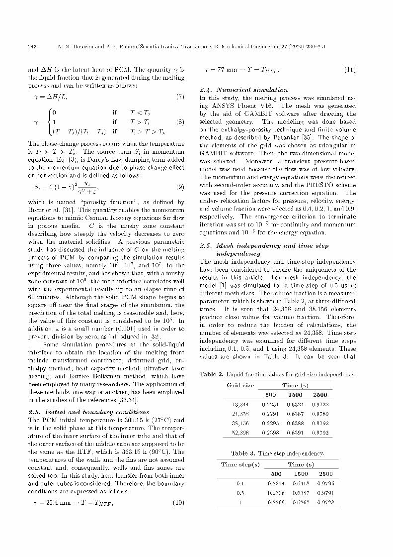
and �H is the latent heat of PCM. The quantity isthe liquid fraction that is generated during the meltingprocess and can be written as follows:
= �H=L; (7)
=
8><>:0 if T < Ts1 if T > Tl(T � Ts)=(Tl � Ts) if Tl > T > Ts
(8)
The phase-change process occurs when the temperatureis Tl � T � Ts. The source term Si in momentumequation, Eq. (3), is Darcy's Law damping term addedto the momentum equation due to phase-change e�ecton convection and is de�ned as follows:
Si = C(1� )2 ui 3 + "
; (9)
which is named \porosity function", as de�ned byBrent et al. [31]. This quantity enables the momentumequations to mimic Carman-Kozeny equations for owin porous media. C is the mushy zone constantdescribing how steeply the velocity decreases to zerowhen the material solidi�es. A previous parametricstudy has discussed the in uence of C on the meltingprocess of PCM by comparing the simulation resultsusing three values, namely 105, 106, and 107, to theexperimental results, and has shown that, with a mushyzone constant of 106, the melt interface correlates wellwith the experimental results up to an elapse time of60 minutes. Although the solid PCM shape begins tosquare o� near the �nal stages of the simulation, theprediction of the total melting is reasonable and, here,the value of this constant is considered to be 106. Inaddition, " is a small number (0.001) used in order toprevent division by zero, as introduced in [32].
Some simulation procedures at the solid-liquidinterface to obtain the location of the melting frontinclude transformed coordinate, deformed grid, en-thalpy method, heat capacity method, ultrafast laserheating, and Lattice Boltzman method, which havebeen employed by many researchers. The application ofthese methods, one way or another, has been employedin the studies of the references [33,34].
2.3. Initial and boundary conditionsThe PCM initial temperature is 300.15 k (27�C) andis in the solid phase at this temperature. The temper-ature of the inner surface of the inner tube and that ofthe outer surface of the middle tube are supposed to bethe same as the HTF, which is 363.15 k (90�C). Thetemperatures of the walls and the �ns are not assumedconstant and, consequently, walls and �ns zones aresolved too. In this study, heat transfer from both innerand outer tubes is considered. Therefore, the boundaryconditions are expressed as follows:
r = 25:4 mm! T = THTF ; (10)
r = 77 mm! T = THTF : (11)
2.4. Numerical simulationIn this study, the melting process was simulated us-ing ANSYS Fluent V16. The mesh was generatedby the aid of GAMBIT software after drawing theselected geometry. The modeling was done basedon the enthalpy-porosity technique and �nite volumemethod, as described by Patankar [35]. The shape ofthe elements of the grid was chosen as triangular inGAMBIT software. Then, the two-dimensional modelwas selected. Moreover, a transient pressure-basedmodel was used because the ow was of low velocity.The momentum and energy equations were discretizedwith second-order accuracy, and the PRESTO schemewas used for the pressure correction equation. Theunder- relaxation factors for pressure, velocity, energy,and volume fraction were selected as 0.4, 0.2, 1, and 0.9,respectively. The convergence criterion to terminateiteration was set to 10�3 for continuity and momentumequations and 10�6 for the energy equation.
2.5. Mesh independency and time stepindependency
The mesh independency and time-step independencyhave been considered to ensure the uniqueness of theresults in this article. For mesh independency, themodel [1] was simulated for a time step of 0.5 usingdi�erent mesh sizes. The volume fraction is a measuredparameter, which is shown in Table 2, at three di�erenttimes. It is seen that 24,358 and 38,156 elementsproduce close values for volume fraction. Therefore,in order to reduce the burden of calculations, thenumber of elements was selected as 24,358. Time stepindependency was examined for di�erent time stepsincluding 0.1, 0.5, and 1 using 24,358 elements. Thesevalues are shown in Table 3. It can be seen that
Table 2. Liquid fraction values for grid size independency.
Grid size Time (s)500 1500 2500
13,344 0.2251 0.6324 0.972224,358 0.2291 0.6387 0.978938,156 0.2295 0.6388 0.979252,396 0.2398 0.6391 0.9792
Table 3. Time step independency.
Time step(s) Time (s)500 1500 2500
0.1 0.2314 0.6418 0.97950.5 0.2306 0.6387 0.97911 0.2269 0.6262 0.9728

M.M. Hosseini and A.B. Rahimi/Scientia Iranica, Transactions B: Mechanical Engineering 27 (2020) 239{251 243
time steps of 0.1 and 0.5 provide approximately closeresults. Therefore, the time step 0.5 is employed so asto decrease the load of calculations.
2.6. ValidationSome of the results of the model presented in [1] havebeen obtained again so as to validate the obtainednumerical results. Streamline, isothermal contour forthe TTHX with internal-external �ns at a 30 mininterval (Figure 14 of Ref. [1]) shown on the left-handside of Figure 2 was reproduced, which is depicted onthe right-hand side of this �gure. The other comparisonis indicated in Figures 3 and 4. As is observed in these�gures, the obtained numerical results are in acceptableagreement with the numerical results of [1].
3. Results and discussions
3.1. Initial study for improving heat transferAs is shown in Figure 5, because of the distanceexisting between the �ns in the TTHX in the modelin Ref. [1], heat cannot quickly spread through theareas far from the �ns and, thus, the phase-changematerial in these areas melts slower and remains inthe solid phase for a longer time of period than thatin the areas near the �ns. Therefore, this structureof the �ns is not suitable to distribute heat uniformlythroughout the cross-section surface of the tube. Tosolve this de�ciency, the length of the �ns is shortened
Figure 2. Comparison of streamline, isothermal contoursfor TTHX �n in 30 minutes.
Figure 3. Comparison of the present numerical resultand numerical results of [1].
Figure 4. Comparison of the present numerical resultand numerical and experimental results of [1].
Figure 5. Melting fraction contours for di�erent cases atthree selected times.
and, instead, their numbers increase, while the totalarea of the �ns remains unchanged. This is done bydividing the length of the �ns by di�erent factors,which are mentioned in Table 4. In each case, allthe �ns are situated at the same distance from eachother. As is indicated in the contours of Figure 5,with a gradual reduction in the length of the �nsand an increase in their numbers, heat is distributedmore uniformly between the �ns and the phase-changematerial than that in the referenced model. However,by continuing this work, the melting rate decreases due

244 M.M. Hosseini and A.B. Rahimi/Scientia Iranica, Transactions B: Mechanical Engineering 27 (2020) 239{251
Table 4. Successive divisions of the �ns for selected division factors.
Divisionfactor
Length ofthe �ns (mm)
Number ofthe �ns
Totalmelting
time (min)Model in [1] 1 42 8 47.5Case 1 2 21 16 38.2Case 2 3 14 24 39.4Case 3 4 10.5 32 44.1Case 4 5 8.4 40 51.6Case 5 10 4.2 80 70.4
Figure 6. Comparison of liquid fraction between thedi�erent cases and the model in [1].
to the creation of a gap between the �ns of the innerand the outer tubes. In Figure 6, liquid fraction curvesfor di�erent cases of this model are indicated.
According to the results shown in Figure 5, thebest heat distribution, which makes the best meltingrate possible, is observed in Case 1 that consists of 16�ns with a length of 21 mm and placed at positionswith a di�erence of 22.5 degrees. This case is namedModel #1. This case provides the shortest melting timeamong the rest of the cases and has a melting time of38.2 minutes, which is shorter than the melting time ofboth of the models in [1,30]. Although the Case 2 yieldsapproximately the same time for complete melting, itsproduction is costlier due to having a greater number of�ns. Therefore, in the following studies, only Model #1will be optimized geometrically in order to increaseits heat transfer and, thus, reduce its total meltingtime. It is important to mention that all the �ns areperpendicular to the tubes throughout this study.
As is seen in Model #1 in Figure 5, the amount ofphase-change materials in the solid phase in the lower
half of the tube is more than that in the upper half.The reason for this phenomenon is the buoyancy force,which causes the liquid material to move upward andthe solid one to move downward. It is implied thatthe liquid part with a higher temperature and lowerdensity moves up, and the solid part that has a lowertemperature and higher density goes down. Hence, inthis model, changing the position and length of the�ns in a way that brings about a rise in the heattransfer in the lower half of the tube makes it possibleto shorten the total melting time of the phase-changematerial and, thus, improve the e�ciency of the heatexchanger. Changing the arrangement of �ns in thismodel causes solid materials to turn into liquid at thesame rate and time both in the top and bottom half ofthe tube. Di�erent variations in the length and positionof the �ns, which are two in uencing parameters forheat transfer, in the triplex heat exchanger will beintroduced thoroughly in the following next sections.
It should be mentioned that selecting any caseswith a division factor less than 2 produces a modelwith a melting time longer than that of Model #1. Forexample, a division factor of 1.5 produces the followingresults in comparison with this model (Tables 5{6 andFigure 7).
3.2. The e�ect of di�erent distances between�ns on the melting rate
In this section, the distances between the �ns arechanged in order to improve the melting time of thephase-change material. This study starts with Model#1 that involves 16 �ns, 8 of them on the outer tubeand 8 on the inner tube, each at 45� away from eachother centrally, as shown in Figure 8. According to theupward movement of liquids with a higher temperature(less density) and the downward movement of solidswith a lower temperature (more density), heat is
Table 5. Comparison of melting time for cases with division factor < 2, i.e. 1:5.
Total melting time (min)Case with division factor < 2, i.e. 1.5 40.7
Model #1 38.2

M.M. Hosseini and A.B. Rahimi/Scientia Iranica, Transactions B: Mechanical Engineering 27 (2020) 239{251 245
Table 6. Successive divisions of the �ns for selected division factors < 2.
Divisionfactor
Length of�ns (mm)
Number of�ns
Model in [1] 1 42 8Case with division factor < 2, i.e. 1.5 1.5 28 12Model #1 2 21 16
Figure 7. Melting fraction contours for di�erent caseswith division factor < 2 at three selected times.
Figure 8. The geometry of Model #1 and di�erentdistances between �ns speci�ed by angels.
trapped in the upper half of the tube, whereas aconsiderable quantity of solids remain in the lower halfof the tube, causing an increase in the total meltingtime. Therefore, to raise the melting rate in the lowerhalf of the tube, angular distances between �ns of lowerhalf of the tube (�1; �2) gradually decrease and, instead,are added to the angular distances between �ns of theupper half of the tube (�3; �4).
According to Table 7 and Figure 8, the centralangles between the lower half �ns of the tube decreasegradually by a step size of 2� and increase the same
Table 7. The values of the di�erent angles between �nsfor showing distances.
�1 �2 �3 �4
Model #1 45 45 45 45
Case 1 43 43 47 47
Case 2 41 41 49 49
Case 3 39 39 51 51
Case 4 37 37 53 53
Case 5 35 35 55 55
Model #2 43 35 51 51
amount between the �ns in the upper half section. Ascan be seen in Figure 9, this gradual change causesan increase in the melting rate in the lower half ofthe tube and, simultaneously, this quantity decreasesin the upper half. This gradual change continues untilthe quantity of solids in the lower half section becomesnegligible. Then, by comparing contours of Cases 1to 5 with di�erent angular distances between the �ns,Model #2 that has the minimum total melting timeamong others is selected, which is 34.283 minutes.The optimization procedure is done by consideringthe point that all solid phase-change materials mustbecome liquid at the same time in both of the topand bottom half of the tube. This optimized modelis shown in Figure 9 as Model #2. In this model,heat is distributed as uniformly as possible, and itsaccumulation in the upper half of the tube decreasesconsiderably.
3.3. The e�ect of di�erent lengths of �ns onthe melting rate
In this section, the lengths of the �ns are changedunequally in order to improve the melting time of thephase-change material. This study starts again withModel #1 that involves 16 �ns of 21 millimeters each(see Figure 10). Further to that, in order to raisethe melting time in the bottom half of the tube, thelengths of all �ns in the upper half are shortened withthe increment of 1 millimeters and are added to thelengths of the lower �ns with the two �ns situated in thehorizontal state (L5) kept unchanged. These changesare shown in Table 8.

246 M.M. Hosseini and A.B. Rahimi/Scientia Iranica, Transactions B: Mechanical Engineering 27 (2020) 239{251
Figure 9. Contours of melting fraction for di�erent casesat three di�erent times.
Figure 10. The geometry of �ns' lengths for di�erentcases.
As is shown in the contours of Figure 11, thegradual increase of the lengths of the �ns in thelower half zone causes an increase in the heat transfersurface and, consequently, boosts the melting rate inthe bottom half of the tube. According to this �gure,the comparison of the contours for di�erent lengths ofthe �ns in the top and bottom half of the tube leads
Figure 11. Contours of melting fraction for di�erentcases at three di�erent times.
to a new model called Model #3. The optimizationprocedure is done by considering the point that allsolid-phase change materials must become liquid atthe same time in both top and bottom half of thetube. This optimized model is shown in Figure 11 asModel #3 with the melting time of 34.150 minutes.This optimized model is able to spread heat uniformlythroughout the cross-section surface of the tube andprovides a minimum total melting time.
3.4. Combination cases of �ns arrangement toincrease the melting rate
Combination cases of the lengths and distances of�ns are considered in this section in order to furtherimprove the melting time. Here, the combinationof Model #1 and Model #2 is considered with theextreme cases of every 16 �ns of Model #1 �rstlyplaced on the outer tube (called Case A), as shownin Figure 12. As is seen from the contours in this�gure, the amount of solid materials in the upper halfof the tube is greater than that in the lower half section.Secondly, all of the �ns in Model #1 are placed on theinner tube (called Case B) and the results are almost

M.M. Hosseini and A.B. Rahimi/Scientia Iranica, Transactions B: Mechanical Engineering 27 (2020) 239{251 247
Table 8. The values of �ns' length for di�erent cases.
L1 L2 L3 L4 L5 L6 L7 L8 L9
Model #1 21 21 21 21 21 21 21 21 21
Case 1 22 22 22 22 21 20 20 20 20
Case 2 23 23 23 23 21 19 19 19 19
Case 3 24 24 24 24 21 18 18 18 18
Case 4 25 25 25 25 21 17 17 17 17
Case 5 26 26 26 26 21 16 16 16 16
Case 6 27 27 27 27 21 15 15 15 15
Case 7 28 28 28 28 21 14 14 14 14
Case 8 29 29 29 29 21 13 13 13 13
Case 9 30 30 30 30 21 12 12 12 12
Case 10 31 31 31 31 21 11 11 11 11
Model #3 22 23 21 30 21 18 18 18 18
Figure 12. Mixed model of Cases A and B.
inverse, meaning that more solid materials remain inthe bottom half of the tube than those in the tophalf. Then, the comparison of the contours of these twomodels results in a new mixed model, which has 7 �nson the inner tube in the top half section and the other 7�ns in the outer tube with the two remaining �ns placedin the horizontal situation. This model is shown inFigure 13 as the mixed model of Cases A and B. As canbe seen in Figure 12, this model bene�ts from both itspredecessors and increases the melting rate throughoutthe cross-section surface of the tube, except some partsat the bottom of the tube. For raising the melting ratein these regions, a new modi�ed model (Model #4) ispresented. Because of the upward movement of theheat, lengths of �ns in the top half of the tube increase
Figure 13. Contours of melting fraction for di�erentcases at three di�erent times.
from the uppermost �n to the lower ones. Moreover,in the bottom half section, lengths of the �ns decreasefrom the lowest �n to the upper one. The �nal lengthsof �ns for this model are presented in Table 9. This isreached by trying to convert all the solid materials inboth of the top and bottom half of the tube into liquidsimultaneously. The resulting model called Model #4is shown in Figure 12 with the melting time of 34.017

248 M.M. Hosseini and A.B. Rahimi/Scientia Iranica, Transactions B: Mechanical Engineering 27 (2020) 239{251
Table 9. The values of �ns' length for di�erent cases.
L1 L2 L3 L4 L5 L6 L7 L8 L9
Mixed model of Cases A and B 21 21 21 21 21 21 21 21 21
Model #4 26 26 24 23 20 24 16 15 14
Table 10. Comparison of complete melting time fordi�erent models.
Complete melting time(min)
Model in [1] 47.533
Model in [30] 39.017
Model #2 34.283
Model #3 34.150
Model #4 34.017
Figure 14. Comparison of melting fraction curves fordi�erent models.
minutes, which is the shortest amount of time amongall the models introduced in this study, as well as thetwo models in [1] and [30]. This is shown in Table 10and Figure 14.
It should be mentioned that Model #4 is reachedafter considering the experience obtained in Sections3.1{3.3 to reach Models #1, #2, and #3. Themodel investigates all possible kinds of changes in thelengths and distances (central angles) on the �ns ofthese models. Some of the intermediate changes alongwith the obtained heat transfer and the correspondingmelting time are shown in Figures 15{18 and Tables11{13, respectively:
- Model #4 with central angles < 22:5 and/or > 22:5;- Model #4 with division factor < 2, i.e. = 1:5;- Model #4 with division factor > 2, i.e. = 2:5.
Table 11. The values of melting times for di�erent cases.
�1 �2 Melting time (min)
Model #4 22.5 22.5 34.017
Case 1 20.5 24.5 35.333
Case 2 21.5 23.5 34.583
Case 3 23.5 21.5 34.733
Case 4 24.5 20.5 34.816
Figure 15. The geometry of Model #4 and di�erentdistances between �ns speci�ed by angels.
4. Conclusions
Di�erent models used to accelerate the melting processof RT82 as phase-change materials were investigatedand introduced in this article. Three methods foroptimizing the model in [1] were presented, resulting inthree mixed models that provide considerably shortermelting time than the original model. For comparingthe contours of melting fraction for the di�erent casesand obtaining the optimized situation in each model,the �ns' lengths and locations were selected in sucha way that the melting of Phase Change Material(PCM) throughout the cross-section surface occurreduniformly and at the same time. Starting from the

M.M. Hosseini and A.B. Rahimi/Scientia Iranica, Transactions B: Mechanical Engineering 27 (2020) 239{251 249
Table 12. The values of �ns' length for di�erent cases.
Model #4 with divisionfactor < 2, i.e. 1.5
L1 L2 L3 L4 L5 L6 L7Melting time
(min)
Case 1 28 28 28 28 28 28 28 35.65
Case 2 34 34 34 28 26 20 18 34.36
Table 13. The values of �ns' length for di�erent cases.
Model #4 withdivision factor > 2,
i.e. 2.5L1 L2 L3 L4 L5 L6 L7 L8 L9 L10 L11
Melting time(min)
Case 1 16.8 16.8 16.8 16.8 16.8 16.8 16.8 16.8 16.8 16.8 16.8 40.06
Case 2 27.8 7.8 25.8 8.8 25.8 5.8 25.8 17.8 14.8 14.8 13.8 34.665
Figure 16. Contours of melting fraction for di�erentcases at three di�erent times.
model in [1] and trying to improve the melting timeof the PCM by equally optimizing the number andlength of the �ns, Model #1 was obtained. Bycompleting the improvement process by optimizing thedistances between the �ns that are measured by thecentral angles, Model #2 was obtained. A combinationof these two models as far as unequal �n's lengths
Figure 17. Contours of melting fraction for di�erentcases at three di�erent times.
Figure 18. Contours of melting fraction for di�erentcases at three di�erent times.
and distances are concerned, considering all possiblecases, enabled the introduction of Model #4 with themelting time of 34.017 minutes for PCM. This meltingtime achieved 28.4% and 12.8% improvement ratescompared to the models in [1] and [30], respectively.

250 M.M. Hosseini and A.B. Rahimi/Scientia Iranica, Transactions B: Mechanical Engineering 27 (2020) 239{251
Nomenclature
Cp Speci�c heat of PCM (J/kg C)G Gravity acceleration (m/s2)H Sensible enthalpy (J/kg)H Enthalpy (J/kg)K Thermal conductivity (W/m K)L Latent heat (W/m K)P Pressure (Pa)T Temperature (K)ui Velocity component (m/s)R Tube radius (m)Si Momentum source term (Pa/m)Ste Stefan numberC Mushy zone constant (kg/m3s)
Greek letters
� Fluid density (kg/m3) Liquid fraction coe�cient� Thermal expansion� Dynamic viscosity (kg/ms)" Constant
Subscripts
i; j Componentsint InitialHTF Heat Transfer Fluidm MeltingRef References SolidL Liquid
References
1 Mat, S., Al-Abidi, A.A., Sopian, K., et al. \Enhanceheat transfer for PCM melting in triplex tube withinternal-external �ns", Energy Conversion and Man-agement, 74, pp. 223{236 (2013).
2 Ghoneim, A. \Comparison of theoretical models ofphase-change and sensible heat storage for air andwater-based solar heating systems", Solar Energy, 42,pp. 209{220 (1989).
3 Agyenim, F., Hewitt, N., Eames, P., et al. \A reviewof materials, heat transfer and phase change problemformulation for latent heat thermal energy storage sys-tems (LHTESS)", Renewable and Sustainable EnergyReviews, 14, pp. 615{628 (2010).
4 Caliskan, H., Dincer, I., and Hepbasli, A. \Thermo-dynamic analyses and assessments of various thermalenergy storage systems for buildings", Energy Conver-sion and Management, 62, pp. 109{122 (2012).
5 Khudhair, A.M. and Farid, M.M. \A review on energyconservation in building applications with thermalstorage by latent heat using phase change materials",Energy Conversion and Management, 45, pp. 263{275(2004).
6 Mazman, M., Cabeza, L.F., Mehling, H., et al. \Uti-lization of phase change materials in solar domestic hotwater systems", Renewable Energy, 34, pp. 1639{1643(2009).
7 Zalba, B., Mar��n, J.M., Cabeza, L.F., et al. \Free-cooling of buildings with phase change materials",International Journal of Refrigeration, 27, pp. 839{849 (2004).
8 Benli, H. \Energetic performance analysis of a ground-source heat pump system with latent heat storagefor a greenhouse heating", Energy Conversion andManagement, 52, pp. 581{589 (2011).
9 Jaworski, M. \Thermal performance of heat spreaderfor electronics cooling with incorporated phase changematerial", Applied Thermal Engineering, 35, pp. 212{219 (2012).
10 Wang, Y.H. and Yang, Y.T. \Three-dimensional tran-sient cooling simulations of a portable electronic deviceusing PCM (phase change materials) in multi-�n heatsink", Energy, 36, pp. 5214{5224 (2011).
11 Pandiyarajan, V., Pandian, M.C., Malan, E., et al.\Experimental investigation on heat recovery fromdiesel engine exhaust using �nned shell and tubeheat exchanger and thermal storage system", AppliedEnergy, 88, pp. 77{87 (2011).
12 Tan, H., Li, C., and Li, Y. \Simulation research onPCM freezing process to recover and store the coldenergy of cryogenic gas", International Journal ofThermal Sciences, 50, pp. 2220{2227 (2011).
13 Gin, B., Farid, M., and Bansal, P. \E�ect of dooropening and defrost cycle on a freezer with phasechange panels", Energy Conversion and Management,51, pp. 2698{2706 (2010).
14 C�akmak, G. and Y�ld�z, C. \The drying kinetics ofseeded grape in solar dryer with PCM-based solarintegrated collector", Food and Bioproducts Processing,89, pp. 103{108 (2011).
15 Buddhi, D., Sharma, S., and Sharma, A. \Thermalperformance evaluation of a latent heat storage unitfor late evening cooking in a solar cooker having threere ectors", Energy Conversion and Management, 44,pp. 809{817 (2003).
16 Li, Z. and Wu, Z.G. \Analysis of HTFs, PCMs and�ns e�ects on the thermal performance of shell-tubethermal energy storage units", Solar Energy, 122, pp.382{395 (2015).
17 Agyenim, F. and Hewitt, N. \The development of a�nned phase change material (PCM) storage systemto take advantage of o�-peak electricity tari� forimprovement in cost of heat pump operation", Energyand Buildings, 42, pp. 1552{1560 (2010).
M.M. Hosseini and A.B. Rahimi/Scientia Iranica, Transactions B: Mechanical Engineering 27 (2020) 239{251 251
18 Xiao, X., Zhang, P., and Li, M. \Preparation andthermal characterization of para�n/metal foam com-posite phase change material", Applied Energy, 112,pp. 1357{1366 (2013).
19 Ali Rabienataj, D., Farhadi, M., Jourabian, M., et al.\Natural convection melting of NEPCM in a cavitywith an obstacle using lattice Boltzmann method", Int.Journal of Numerical Methods for Heat & Fluid Flow,24, pp. 221{236 (2013).
20 Fan, L. and Khodadadi, L.J. \An experimental in-vestigation of enhanced thermal conductivity and ex-pedited unidirectional freezing of cyclohexane-basednanoparticle suspensions utilized as nano-enhancedphase change materials (NePCM)", Int. Journal ofThermal Sciences, 62, pp. 120{126 (2012).
21 Hosseini, M., Ranjbar, A., Rahimi, M., et al. \Ex-perimental and numerical evaluation of longitudinally�nned latent heat thermal storage systems", Energyand Buildings, 99, pp. 263{272 (2015).
22 Al-Abidi, A.A., Mat, S., Sopian, K., et al. \Experi-mental study of melting and solidi�cation of PCM ina triplex tube heat exchanger with �ns", Energy andBuildings, 68, pp. 33{41 (2014).
23 Esapour, M., Hosseini, M., Ranjbar, A., et al. \Phasechange in multi-tube heat exchangers", RenewableEnergy, 85, pp. 1017{1025 (2016).
24 Ho, C.R., Siao, Y.H., and Yan, W.M. \Thermal energystorage characteristics in an enclosure packed withMEPCM particles: An experimental and numericalstudy", Int. Journal of Heat and Mass Transfer, 73,pp. 88{96 (2014).
25 Siao, Y.H., Yan, W.M., and Lai, C.M. \Transientcharacteristics of thermal energy storage in an enclo-sure packed with MEPCM particles", Applied ThermalEngineering, 88, pp. 47{53 (2015).
26 Ho, C., Liu, K., and Yan, W.M. \Simulation onmelting processes in a vertical rectangular enclosurewith a free-moving ceiling", Int. Journal of Heat andMass Transfer, 83, pp. 222{228 (2015).
27 Darzi, A.A.R., Jourabian, M., and Farhadi, M. \Melt-ing and solidi�cation of PCM enhanced by radial con-ductive �ns and nanoparticles in cylindrical annulus",Energy Conversion and Management, 118, pp. 253{263 (2016).
28 Mahdi, J.M. and Nsofor, E.C. \Melting enhancementin triplex-tube latent thermal energy storage systemusing nanoparticles-�ns combination", Int. Journal ofHeat and Mass Transfer, 109, pp. 417{427 (2017).
29 Al-Abidi, A.A., Mat, S., Sopian, K., et al. \Internaland external �n heat transfer enhancement techniquefor latent heat thermal energy storage in triplex tubeheat exchangers", Applied Thermal Engineering, 53,pp. 147{156 (2013).
30 Eslamnezhad, H. and Rahimi, A.B. \Enhance heattransfer for phase-change materials in triplex tube heatexchanger with selected arrangements of �ns", AppliedThermal Engineering, 113, pp. 813{821 (2017).
31 Brent, A., Voller, V., and Reid, K. \Enthalpy-porosity technique for modeling convection-di�usionphase change: application to the melting of a puremetal", Numerical Heat Transfer, Part A Applications,13, pp. 297{318 (1988).
32 Ye, W.B., Zhu, D.S., and Wang, N. \Numericalsimulation on phase-change thermal storage/release ina plate-�n unit", Applied Thermal Engineering, 31, pp.3871{3884 (2011).
33 Ghaebi, H., Bahadori, M.N., and Saidi, M.H. \Para-metric study of the pressure distribution in a con�nedaquifer employed for seasonal thermal energy storage",Scientia Iranica, 22(1), pp. 235{244 (2015).
34 Sa�khani, H., Ahmari, M., and Azadehfar, E. \Nu-merical study of conjugate heat transfer in laminarand turbulent nano uid ow in double pipe heatexchangers", Scientia Iranica, 23(5), pp. 2211{2219(2016).
35 Patankar, S., Numerical Heat Transfer and Fluid Flow,CRC press, London, U.K. (1980).
Biographies
Mohammad M. Hosseini was born in Mashhad,Iran, 1990. He received his BS degree in MechanicalEngineering from Birjand University in 2014 and hisMS degree in Mechanical Engineering from FerdowsiUniversity of Mashhad, Mashhad, Iran in 2018.
Asghar Baradaran Rahimi was born in Mashhad,Iran, 1951. He received his BS degree in MechanicalEngineering from Tehran Polytechnic, 1974 and a PhDdegree in Mechanical Engineering from the Universityof Akron, Ohio, U.S.A., 1986. He has been a Profes-sor at the Department of Mechanical Engineering atFerdowsi University of Mashhad since 2001. His re-search and teaching interests include heat transfer and uid dynamics, gas dynamics, continuum mechanics,applied mathematics, and singular perturbations.