improving common security risk analysis · various nato countries such as ebios for france, cramm...
TRANSCRIPT

NORTH ATLANTIC TREATY ORGANISATION
RESEARCH AND TECHNOLOGYORGANISATION
AC/323(IST-049)TP/193 www.rto.nato.int
RTO TECHNICAL REPORT TR-IST-049
Improving Common Security Risk Analysis
(Amélioration d’un processus commun d’analyse de risques sécurité)
Final Report of Task Group IST-049.
Published September 2008
Distribution and Availability on Back Cover


NORTH ATLANTIC TREATY ORGANISATION
RESEARCH AND TECHNOLOGYORGANISATION
AC/323(IST-049)TP/193 www.rto.nato.int
RTO TECHNICAL REPORT TR-IST-049
Improving Common Security Risk Analysis
(Amélioration d’un processus commun d’analyse de risques sécurité)
Final Report of Task Group IST-049.

ii RTO-TR-IST-049
The Research and Technology Organisation (RTO) of NATO
RTO is the single focus in NATO for Defence Research and Technology activities. Its mission is to conduct and promote co-operative research and information exchange. The objective is to support the development and effective use of national defence research and technology and to meet the military needs of the Alliance, to maintain a technological lead, and to provide advice to NATO and national decision makers. The RTO performs its mission with the support of an extensive network of national experts. It also ensures effective co-ordination with other NATO bodies involved in R&T activities.
RTO reports both to the Military Committee of NATO and to the Conference of National Armament Directors. It comprises a Research and Technology Board (RTB) as the highest level of national representation and the Research and Technology Agency (RTA), a dedicated staff with its headquarters in Neuilly, near Paris, France. In order to facilitate contacts with the military users and other NATO activities, a small part of the RTA staff is located in NATO Headquarters in Brussels. The Brussels staff also co-ordinates RTO’s co-operation with nations in Middle and Eastern Europe, to which RTO attaches particular importance especially as working together in the field of research is one of the more promising areas of co-operation.
The total spectrum of R&T activities is covered by the following 7 bodies: • AVT Applied Vehicle Technology Panel • HFM Human Factors and Medicine Panel • IST Information Systems Technology Panel • NMSG NATO Modelling and Simulation Group • SAS System Analysis and Studies Panel • SCI Systems Concepts and Integration Panel
• SET Sensors and Electronics Technology Panel
These bodies are made up of national representatives as well as generally recognised ‘world class’ scientists. They also provide a communication link to military users and other NATO bodies. RTO’s scientific and technological work is carried out by Technical Teams, created for specific activities and with a specific duration. Such Technical Teams can organise workshops, symposia, field trials, lecture series and training courses. An important function of these Technical Teams is to ensure the continuity of the expert networks.
RTO builds upon earlier co-operation in defence research and technology as set-up under the Advisory Group for Aerospace Research and Development (AGARD) and the Defence Research Group (DRG). AGARD and the DRG share common roots in that they were both established at the initiative of Dr Theodore von Kármán, a leading aerospace scientist, who early on recognised the importance of scientific support for the Allied Armed Forces. RTO is capitalising on these common roots in order to provide the Alliance and the NATO nations with a strong scientific and technological basis that will guarantee a solid base for the future.
The content of this publication has been reproduced directly from material supplied by RTO or the authors.
Published September 2008
Copyright © RTO/NATO 2008 All Rights Reserved
ISBN 978-92-837-0045-6
Single copies of this publication or of a part of it may be made for individual use only. The approval of the RTA Information Management Systems Branch is required for more than one copy to be made or an extract included in another publication. Requests to do so should be sent to the address on the back cover.

RTO-TR-IST-049 iii
Table of Contents
Page
List of Figures/Tables vi
Membership of Task Group vii
Executive Summary and Synthèse ES-1
Chapter 1 – Versions 1-1
Chapter 2 – Introduction 2-1 2.1 Rationale 2-1 2.2 References to Risk Assessment and Risk Analysis within NATO Documentation 2-1 2.3 Role of Risk Analysis 2-1 2.4 Glossary 2-5 2.5 References 2-7 2.6 Reference Web Sites 2-8 2.7 Scope and Objectives 2-8 2.8 Acknowledgment 2-8
Chapter 3 – Review of Existing Methodologies 3-1 3.1 Overview of the Selected Methodologies 3-1
3.1.1 CRAMM 3-1 3.1.1.1 Introduction 3-1 3.1.1.2 Description 3-1
3.1.2 EBIOS ® 3-3 3.1.2.1 History 3-3 3.1.2.2 Description 3-4
3.1.3 Overview of Canadian TRA Methodology 3-9 3.1.3.1 Using TRA in Risk Management 3-9 3.1.3.2 Risk Management Tools 3-10
3.1.4 US 3-15 3.1.4.1 Introduction 3-15 3.1.4.2 Objective 3-15 3.1.4.3 Basic Risk Management 3-15 3.1.4.4 Department of Defense (DoD) Information Technology Security 3-21
Certification and Accreditation Process (DITSCAP) 3.1.4.5 Conclusion 3-21
3.1.5 Czech Methodology 3-22 3.1.6 Spanish Method MAGERIT 3-23
3.1.6.1 Step 1: Assets 3-24

iv RTO-TR-IST-049
3.1.6.2 Step 2: Threats 3-24 3.1.6.3 Step 4: Determination of the Impact 3-25 3.1.6.4 Step 5: Determination of the Risk 3-26 3.1.6.5 Step 3: Safeguards 3-27 3.1.6.6 Revision of Step 4: Residual Impact 3-27 3.1.6.7 Revision of Step 5: Residual Risk 3-28
3.2 Comparative Analysis 3-28 3.3 Alternative Methods 3-35
Chapter 4 – Common Criteria and Risk Analysis 4-1 4.1 Common Method Using Common Criteria 4-1
4.1.1 Similarities and Differences Between CC and TRA 4-2 4.1.2 Using CC with TRA 4-2 4.1.3 Protection Profile and TRA 4-4
4.2 Critical Aspects of Common Criteria Evaluation 4-4 4.2.1 CC and TRA Summary 4-6
4.3 Security Requirements and CC 4-7
Chapter 5 – Risk Analysis Tools 5-1 5.1 Existing Tools 5-1
5.1.1 EBIOS Tool 5-1 5.1.2 CRAMM 5-1 5.1.3 RISKAN 5-1 5.1.4 PILAR / EAR 5-1 5.1.5 Comparative Analysis 5-1
Chapter 6 – Definition of a Common Methodology 6-1 6.1 The Different Components of Risk Analysis 6-1 6.2 Generic Risk Assessment Framework 6-1
Chapter 7 – Recommendations 7-1 7.1 Dynamic Risk Analysis 7-1 7.2 Information Exchange Requirements 7-1
7.2.1 For Systems Interconnections 7-1 7.2.2 To Update a Common Threat and Vulnerability Repository 7-1 7.2.3 Within a Coalition 7-1
7.3 Proposed Evolutions of Existing Methods and Tools 7-3 7.4 Follow on Activities 7-3
7.4.1 Within RTO/IST 7-3 7.4.2 Within Other NATO Entities 7-4
Annex A – Composed Systems A-1 A.1 Composed Systems A-1

RTO-TR-IST-049 v
A.2 Vertical Assurance A-2 A.3 Structural Assurance A-2 A.4 A Note on Complexity Theory A-3
Annex B – Examples of Attack Methods (from EBIOS) B-1
Annex C – Examples C-1 C.1 Asset Types C-1 C.2 Threats Description C-12 C.3 Vulnerabilities Description C-12

vi RTO-TR-IST-049
List of Figures/Tables
Figure Page
Figure 2-1 Risk Management Process 2-2 Figure 3-1 High Level Structure of CRAMM Methodology 3-2 Figure 3-2 Risk Management Model 3-10 Figure 3-3 Risk Assessment Methodology Flow Chart 3-16 Figure 3-4 Risk Decision Flow Chart 3-19 Figure 3-5 Risk Management Process 3-20 Figure 3-6 Risk Management Cycle 3-20 Figure 3-7 MAGERIT Main Steps 3-23 Figure 3-8 MAGERIT Main Steps, including Safeguards 3-27 Figure 7-1 DRA, Alternative Architectures for Coalitions 7-2
Table
Table 3-1 Potential of the Attacker 3-8 Table 3-2 TRA Process Tasks 3-12 Table 3-3 Likelihood Definitions 3-17 Table 3-4 Magnitude of Impact Definitions 3-18 Table 3-5 Comparative Analysis 3-29 Table 4-1 CC V 2.1 Documents Useful for TRA 4-3 Table 5-1 Comparative Analysis 5-2 Table 6-1 Generic Risk Assessment Framework 6-2

RTO-TR-IST-049 vii
Membership of Task Group
Task Group Chairman
Dip. Eng Jean-Pierre LEBEE DGA/DCE/CELAR
BP 7, 35998 RENNES Armées France
[email protected] Tel: +33 (0) 2 99.42.98.68 Fax: +33 (0) 2 99.42.64.50
Task Group Members
BELGIUM Maj. Dr. Wim MEES Ecole Royale Militaire Computer Science Department 30 Renaissancelaan B-1000 Brussels Email: [email protected] Tel: +32 (2) 737.65.13 Fax: +32 (2) 737.65.12 CANADA Dr. Jean SAVOIE Defence R&D Canada – Ottawa 3701 Carling Ave Ottawa, Ontario K1A 0Z4 Email: [email protected] Tel: +1 (613) 993-5132 Fax: +1 (613) 993-9940 CZECH REPUBLIC Dip. Ir. Michal VANECEK T-SOFT s.r.o., Novodvorská 1010/14 142 01 Prague 4 Email: [email protected] Tel: +420 (2) 61.34.87.38Fax: +420 (2) 61.34.87.91 UNITED STATES Ms. Phyllis JENKET Code 5544, Naval Research Laboratory 4555 Overlook Ave SW Washington DC, 20375-5337 Email: [email protected] Tel: 001.843.218.5444
Mr. Rodney STALKER Code 5541 Naval Research Laboratory 4555 Overlook Ave SW Washington, DC 20375-5337 Email: [email protected] Tel: 001.301.757.2986 NATO C3 AGENCY Dip. Eng Frederic JORDAN INFOSEC & Cyber Defence Senior INFOSEC Engineer NATO C3 Agency, PO Box 174 2501 CD, The Hague Netherlands Email: [email protected] Tel: 31-70-374-3486 NHQC3S Dip. Eng Franck ROUSSET Staff Officer Boulevard Léopold III B-1110 Brussels Belgium Email: [email protected] Tel: +32 (0)2 707 54 24 Fax: +32 (0)2 707 58 34

viii RTO-TR-IST-049

RTO-TR-IST-049 ES - 1
Improving Common Security Risk Analysis (RTO-TR-IST-049)
Executive Summary This report is the final report resulting from the four meetings of the working group called “Improving Common Security Risk Analysis” (IST-049 – RTG-021). The report describes the different methods used by various NATO countries such as EBIOS for France, CRAMM for UK, ITSG-04 for Canada, MAGERIT for Spain. As a first conclusion, the report shows that these methodologies, even if based on similar principles, differ in their knowledge bases (assets, threats, vulnerabilities, …) or type of results (quantitative or qualitative). This makes the risk assessments difficult or impossible to compare when different methods have been used.
In a second part, the report identifies the main steps which are considered as mandatory for a method to be used by NATO.
Then the report identifies recommendations which should be taken into account by the existing methods and tools in order to solve the interoperability problem identified in the first part of the document but also to be able to take into account the new NATO concepts such as NNEC. These recommendations mainly concern the integration of dynamic risk analysis and improvement of information exchange. A proposal list of evolution for existing methods and tools concludes this part. The main results are:
• Methods should be based on documented models and should be modular. • Methods should use a technical repository for assets, threats and vulnerabilities. • Methods should be quantitative instead of qualitative. • Methods should use the principle of refinement (more depth). • Methods should allow reusability: it should be possible to reuse the result of a previous risk
analysis on a system, sub system or component and to include these results in a new analysis. • Methods should allow the reuse of the vulnerabilities analysis done during a product evaluation
(CC, FIPS 140-1) or a system security testing (vulnerabilities scan, IDS, …). • Tools should be able to implement accurately the methods, to interface with external repositories,
and to offer a user friendly interface. • When performing risk assessment or when identifying countermeasures, tools shall be able to take
into account the standard NATO security measures (physical, procedural) and the NATO technical security requirements.
• Tools should offer functionalities to conduct high level risk analysis in a time frame coherent with the new needs for system deployment and accreditation. Detailed risk analysis should be refined from these high level ones if necessary.
• Tools should offer simulation capabilities or at a minimum extended “What if” functions, in order, for example, to select the most appropriate countermeasure or to identify the impact of a change in threat level, in system architecture / configuration.
The final chapter of the report identifies the follow on activities to be conducted within RTO/IST or within other NATO entities.

ES - 2 RTO-TR-IST-049
Amélioration d’un processus commun d’analyse de risques sécurité
(RTO-TR-IST-049)
Synthèse Ceci est le rapport final clôturant les quatre réunions du groupe de travail intitulé « Amélioration d’un processus commun d’analyse de risques sécurité » (IST-049 – RTG-021). Il décrit les différentes méthodes utilisées par diverses nations de l’OTAN, telles que EBIOS pour la France, CRAMM pour le Royaume-Uni, ITSG-04 pour le Canada ou MAGERIT pour l’Espagne. La première conclusion de ce rapport démontre que ces méthodologies, même si elles sont fondées sur des principes similaires, divergent dans leurs bases de connaissances (atouts, menaces, vulnérabilités, …) ou leur type de résultats (quantitatif ou qualitatif). Lorsque des méthodes différentes ont été employées, il devient difficile, voire impossible, de comparer les évaluations de risques.
Dans une deuxième partie, ce rapport identifie les principales étapes considérées comme obligatoires pour qu’une méthode soit utilisée par l’OTAN.
Ce rapport détermine ensuite les recommandations qui devraient être prises en compte par les méthodes et les outils existants afin de résoudre les problèmes d’interopérabilité recensés en première partie du document, mais également afin de pouvoir intégrer les nouveaux concepts de l’Alliance, tels que la capacité en réseau de l’OTAN (NNEC). Ces recommandations concernent principalement l’intégration des analyses de risques dynamiques et l’amélioration des échanges d’informations. Une liste de propositions d’améliorations pour les méthodes et outils existants conclut cette partie. Les principaux résultats sont les suivants :
• Les méthodes devraient être basées sur des simulations documentées et devraient être modulaires. • Les méthodes devraient utiliser un référentiel technique pour les biens, les menaces et les
vulnérabilités. • Les méthodes devraient être quantitatives et non qualitatives. • Les méthodes devraient utiliser le principe du rafinement (plus de profondeur). • Les méthodes devraient permettre la réutilisation : il devrait être possible de réutiliser le résultat
d’une précédente analyse de risques sur un système, un sous-système ou un composant et d’inclure ces résultats dans une nouvelle analyse.
• Les méthodes devraient permettre la réutilisation de l’analyse des vulnérabilités réalisée lors de l’évaluation d’un produit (CC, FIPS 140-1) ou des tests de sécurité d’un système (scanner de vulnérabilités, IDS, …).
• Les outils devraient être capables d’implémenter les méthodes avec précision, d’interfacer avec les référentiels externes et de proposer une interface conviviale.
• Lors de la réalisation d’une évaluation des risques ou de l’identification de contre-mesures, les outils devraient être capables de prendre en compte les mesures de sécurité standard de l’OTAN (physiques, de procédure) et les exigences de sécurité techniques de l’OTAN.
• Les outils devraient proposer des fonctionnalités permettant de réaliser des analyses de risques de haut niveau dans un cadre temporel cohérent avec les nouveaux besoins en matière d’accréditation

RTO-TR-IST-049 ES - 3
et de déploiement de système. Des analyses de risques détaillées devraient être affinées à partir de ces analyses de haut niveau si nécessaire.
• Les outils devraient proposer des capacités de simulation ou, au minimum, des fonctions « What If » (quoi si) avancées afin, par exemple, de sélectionner la contre-mesure la plus appropriée ou d’identifier l’impact d’une modification du niveau de menace, dans l’architecture ou la configuration du système.
Le dernier chapitre de ce rapport identifie les activités de suivi à mettre en place au sein de la RTO/IST ou d’autres entités de l’OTAN.

ES - 4 RTO-TR-IST-049

RTO-TR-IST-049 1 - 1
Chapter 1 – VERSIONS
Version Date Changes
V0.1 April 2004 Creation
V0.2 November 2004 Update during the 2nd WG
February 2005 FR: add:
A glossary
An EBIOS description
V0.3 November 2005 Add Sections 2 and 4
V0.6 January 2006 Draft version not distributed
V0.7 January 2006 Update during the 3rd meeting
V0.8 November 2006 Update during the 4th meeting
V1.0 December 2006 Final version

VERSIONS
1 - 2 RTO-TR-IST-049

RTO-TR-IST-049 2 - 1
Chapter 2 – INTRODUCTION
2.1 RATIONALE
During the 7th IST panel an exploratory team titled “Improving security awareness” was proposed. Following the 11th of September events in USA, the new focus put on anti-terrorism activities conducted the Panel Members to rename the exploratory team to “Improving common security risk analysis” during the 8th IST panel.
Today many NATO nations use national risk analysis methodologies (for example EBIOS for France, CRAMM for UK, ITSG-04 for Canada, MAGERIT for Spain). These methodologies, even if based on similar principles, use different threat and vulnerabilities classification. The increase of interoperability between national and NATO systems requires building up a common risk analysis methodology. A Canadian contribution received in September 2001 pointed up the need for a common NATO classification for threats and vulnerabilities.
To counter or mitigate the gaps in NATO capabilities against Cyber Defence, the Heads of State and Government agreed at the Prague Summit to improve Cyber Defence in NATO. The capability to continuously assess and manage the risk has been identified as a priority 1 measure.
This activity can be linked with the following requirements from NATO strategic commands (from the document RTO programme and NATO requirements: RTA/SPD (2004-03) PG2004):
• MF03: Intelligence support: need for a real time NATO security alert system (page 22).
• MF03: Need to develop intelligence collection and analysis tools (page 23).
• MF03: Need for advanced analytical tools for threat assessment (page 24).
And with Defence capabilities initiatives:
• Sustainability and logistics: NATO nations should enhance interoperability … (page 88).
• Survivability of forces and infrastructure: the alliance shall review the vulnerability … (page 107).
2.2 REFERENCES TO RISK ASSESSMENT AND RISK ANALYSIS WITHIN NATO DOCUMENTATION
C-M(2002)49: Security within the North Atlantic Treaty Organisation, enclosure F, §15: “Systems handling NATO classified information, in NATO civil and military bodies, shall be subject to risk assessment and risk management in accordance with the requirements of directives supporting this policy.”
AC/35-D/2004: Primary directive on INFOSEC: Security Risk Assessment and Risk Management, §11 to 18.
AC/35-D/2005: INFOSEC Management Directive.
2.3 ROLE OF RISK ANALYSIS
Everyone takes and manages risks all the time, balancing potential rewards against uncertain losses. Risk management remains nevertheless a very difficult process. It requires combining the ‘‘hard’’

INTRODUCTION
2 - 2 RTO-TR-IST-049
scientist’s approach, who treats risks as something that can be objectively measured, with the view of the ‘‘social’’ scientist who argues that risk is a fuzzy concept and the propensity to take risks is in part culturally constructed.
A risk is the chance of something going wrong as a result of a hazard or a threat which has an impact on operations. Risks arise out of uncertainty. A risk is measured in terms of its likelihood of happening and the consequences if it should happen. Risk management is balancing the cost of avoiding, reducing, transferring or accepting a risk with the benefits that can be expected from taking the risk.
Taking a risk incurs the possibility of suffering loss. This loss may or may not happen. When a negative event or issue is a certainty, it is considered to be a problem, not a risk. Problems are out of the scope of the risk management process.
The term risk management is used in a wide variety of disciplines, and itself also combines concepts and techniques from a range of fields like statistics, economics, operations research and decision theory.
When different organizations need to put in place a link between their information systems in order to exchange privileged information, for instance in the context of a ‘‘Global Information Grid’’ (GIG), it is necessary to manage the risks that such a link inevitably introduces.
Unfortunately, there are no standards for defining vulnerabilities and threat-sources, assigning and combining impact and probability ratings, or introducing the impact of controls in the field of information security related risk management. Different methodologies and tools use different definitions and approaches. It is therefore difficult to import the risks identified and assessed by a coalition member for his system in a straightforward way into another coalition member’s risk management process.
Recent standards and recommendations on the management of information systems and organizing the protection of information security within an organization widely recognize the importance of information security related risk management.
Figure 2-1: Risk Management Process.

INTRODUCTION
RTO-TR-IST-049 2 - 3
Risk management processes typically include the following four steps:
• Establish the Scope
The first step in any risk management process consists in defining the scope of the risk management process, in other words the information system that is the target of the evaluation, its boundaries and environment, as well as the identity and objectives of the stakeholders.
The characterization of the system must be as complete as possible and most often includes the following elements:
• Hardware (e.g. servers, workstations, network equipment);
• Software (e.g. operating systems, system services, application software);
• Connectivity (internal and external);
• The information system’s mission;
• The information that is managed by the system and its requirements regarding availability, integrity and confidentiality;
• Support staff and users; and
• Existing controls: technical controls (e.g. user identification and authentication equipment, encryption hardware and software), management controls (e.g. security policy, acceptable use policy), operational controls (e.g. backup and contingency operations, off-site storage, user account creation and deletion procedures), physical security environment (e.g. site security, data center policies), environmental security (e.g. controls for power, temperature, humidity).
• Identify the Risks
The second step of the risk management process consists in establishing a list of the risks to which the information system is exposed.
First, based on the system and context description available at the end of the previous step, the vulnerabilities that apply to the target of the evaluation are identified.
A vulnerability is any flaw or weakness in the design of a system, in its implementation or in the controls that are in place to protect it, that can result in damage when it is accidentally triggered or intentionally exploited.
A threat-source is either the combination of the intent and the means to intentionally exploit a vulnerability (e.g. a thief, a disgruntled employee) or a situation that may accidentally trigger a vulnerability (e.g. an earthquake, a sloppy user).
A threat is the potential for a threat-source to accidentally trigger or intentionally exploit a vulnerability. When for a given vulnerability there is no threat-source that has the technical ability or motivation to exploit it, there is no threat. Likewise, when there is no vulnerability present for which a given threat-source has the necessary skills, time and budget, this threat-source poses no threat.
Each threat is after that matched with the list of controls that were identified in the first phase, and that mitigate the likelihood of a vulnerability being exercised or reduce the impact of such an adverse event when it occurs. The resulting tuple (threat, threat-source, list of relevant controls) defines the risk that will be assessed and treated in the subsequent steps.

INTRODUCTION
2 - 4 RTO-TR-IST-049
• Analyze the Risks
In this step, the risks that were identified, are to be analyzed in more detail, so that in the step hereafter the minor, acceptable risks can be separated from the major risks which must absolutely be eliminated or reduced.
This involves deriving for each risk an overall likelihood rating that indicates the probability that the vulnerability may be exercised by the corresponding threat-source. The second element in risk assessment is trying to rate the adverse impact of the vulnerability when it were to be exercised. This rating will be based on an evaluation of the loss or degradation of integrity, availability, and confidentiality of the information that is threatened by the vulnerability.
When determining the probability and impact of a threat, the existing controls that reduce the likelihood or impact and their adequacy have to be taken into account.
The combination of probability and impact will finally be translated into a single level of risk to the information system, for instance using a risk-level matrix.
• Treat the Risks
Risks can be handled in a number of ways:
• Risk Avoidance: means simply not performing the activity that carries the risk.
Unfortunately this also typically means losing out on the potential gain that performing the activity might have produced.
• Risk Reduction: involves approaches that reduce the probability of the vulnerability being triggered or reduce the impact when the vulnerability is triggered.
Reducing a risk most often involves putting in place controls.
• Risk Transfer: means passing the risk on to another party that is willing to accept the risk, typically by contract or by hedging.
Insurance is an example of risk transfer using contracts.
• Risk Retention: means accepting the loss when it occurs.
Risk retention is a viable strategy for small-impact risks where the cost of insuring against the risk would be greater over time than the total losses sustained.
Also, all risks that are not avoided nor transferred, and that one does not can or wish to reduce any further, automatically fall under this category. This includes risks that are so large or catastrophic that they either cannot be insured against or the premiums would be infeasible.
The combination of methods used to handle each of the risks that were identified, analyzed and treated, leads to a risk management plan, that must then be implemented.
Risk management can be performed once for a given system, for instance before it comes in operation, and then periodically updated during the lifetime of the system. The back coupling, shown in Figure 2-1 above, is in this case not permanent but rather periodically triggered. Risks management can however also be conceived as a continuous process and influence decision-making at all instances through the life of the system.

INTRODUCTION
RTO-TR-IST-049 2 - 5
2.4 GLOSSARY
Term Definition Source
Acceptable Risk A judicious and carefully considered assessment by the appropriate Designated Approving Authority (DAA) that an information technology (IT) activity [system], or network meets the minimum requirements of applicable security directives. The assessment should take into account the value of IT assets; threats and vulnerabilities; countermeasures and their efficiency in compensating for vulnerabilities; and operational requirements.
CSE ITSG-04
Accountability Property that allows the ability to identify, verify, and trace system entities as well as changes in their status. Accountability is considered to include authenticity and non-repudiation.
NIST SP800-37
Accountability, security goal
The security goal that generates the requirement for actions of an entity to be traced uniquely to that entity. This support non-repudiation, deterrence, fault isolation, intrusion detection and prevention, and after-action recovery and legal action.
NIST SP800-30
Asset Information or resources to be protected by the countermeasures of a Target Of Evaluation (TOE).
Assets types include: information, hardware, communications equipment, firmware, documents/publications, environmental equipment, people/staff, infrastructure, goodwill, money, income, organizational integrity, customer confidence, services and organizational image.
Common Criteria
CSE ITSG-04
Asset, Value A measure of asset worth in terms of replacement cost, confidentiality, integrity, availability [or other elements]. Values vary from asset to asset. They are used for many purposes such as representing levels of importance to the “business” or operations/operational mission of an organization.
CSE ITSG-04
Assurance [security objectives]
Ground for confidence that an entity meets its security objectives.
Common Criteria
Attack The act of aggressively trying to bypass security controls on an IT system or network. The fact that the attack is made does not mean it will succeed. The success depends on the vulnerability of the system, network or activity and the effectiveness of the safeguards in place.
CSE ITSG-04
Attack potential The perceived potential for success of an attack, should an attack be launched, expressed in terms of an attacker’s expertise, resources and motivation. [Similar to threat level for threat scenarios]
Common Criteria

INTRODUCTION
2 - 6 RTO-TR-IST-049
Term Definition Source
Availability The security goal that generates the requirement for protection against:
• Intentional or accidental attempts to: 1) Perform unauthorized deletion of data; or 2) Otherwise cause a denial of service or data.
• Unauthorized use of system resources.
NIST SP800-30
Confidentiality The security goal that generates the requirement for protection from intentional or accidental attempts to perform unauthorized data reads. Confidentiality covers data in storage, during processing, and in transit.
NIST SP800-30
Countermeasures Actions, devices, procedures, techniques, or other measures that reduce the vulnerability of an information system. Synonymous with security controls and safeguards.
NIST SP800-53
Criticality/sensitivity A measure of the importance and nature of the information processed, stored, and transmitted by the IT system to the organization’s mission and day-to-day operations.
NIST SP800-37
Denial of Service The prevention of authorized access to resources or the delaying of time-critical operations.
NIST SP800-30
Impact A measure of the degree of damage or other change caused by a threat event.
CSE ITSG-04
Integrity The security goal that generates the requirement for protection against either intentional or accidental attempts to violate data integrity (the property that data has when it has not been altered in an unauthorized manner) or system integrity (the quality that a system has when it performs its intended function in an unimpaired manner, free from unauthorized manipulation).
NIST SP800-30
IT-Related Risk The net mission impact considering:
1) The probability that a particular threat-source will exercise (accidentally trigger or intentionally exploit) a particular information system vulnerability.
2) The resulting impact if this should occur. IT-related risks arise from legal liability or mission loss due to: a) Unauthorized (malicious or accidental) disclosure,
modification, or destruction of information; b) Unintentional errors and omissions; c) IT disruptions due to natural or man-made
disasters; or d) Failure to exercise due care and diligence in the
implementation and operation of the IT system.
NIST SP800-30
Residual Risk The risk that remains after risk treatment. ISO 17799

INTRODUCTION
RTO-TR-IST-049 2 - 7
Term Definition Source
Risk Acceptance An action taken by the responsible manager to declare and be held accountable for acceptance of the remaining or residual risks attributed to an IT system after the performance of a threat and risk assessment. Generally, the acceptance of the residual risk is made because any further addition of safeguards does not justify the effort in terms of cost or functionality.
CSE ITSG-04
Risk Assessment The process of identifying the risks to system security and determining the probability of occurrence, the resulting impact, and additional safeguards that would mitigate this impact. Part of Risk Management and synonymous with Risk Analysis.
NIST SP800-30
Risk Management The total process of identifying, controlling, and mitigating information system–related risks. It includes risk assessment, cost-benefit analysis, and the selection, implementation, test, and security evaluation of safeguards. This overall system security review considers both effectiveness and efficiency, including impact on the mission and constraints due to policy, regulations, and laws.
NIST SP800-30
SISRS System Interconnection Security Requirement Statement
Threat The potential for a threat-source to exercise (accidentally trigger or intentionally exploit) a specific vulnerability.
NIST SP800-30
Threat-source Either: 1) Intent and method targeted at the intentional
exploitation of a vulnerability; or 2) A situation and method that may accidentally trigger a
vulnerability.
NIST SP800-30
Threat Analysis The examination of threat-sources against system vulnerabilities to determine the threats for a particular system in a particular operational environment.
NIST SP800-30
Vulnerability A flaw or weakness in system security procedures, design, implementation, or internal controls that could be exercised (accidentally triggered or intentionally exploited) and result in a security breach or a violation of the system’s security policy.
NIST SP800-30
2.5 REFERENCES
NIST SP-800-30: Risk Management Guide for Information Technology Systems.
ISO 73: Risk Management.
ISO 13335: Guidelines for the management of IT Security.
ISO 17799: Code of practice for information security management.
ISO 15408: Common Criteria.

INTRODUCTION
2 - 8 RTO-TR-IST-049
A New Model for Computer Security Risk Analysis, Capt. Sophie Martel, M.SC. Thesis, Carleton University, Ottawa, June 2002.
ITSG-04 – Threat and Risk Assessment Working Guide, October 1999. The ITSG-04 provides guidance to an individual (or a departmental team) in carrying out a Threat and Risk Assessment (TRA) for an existing or proposed IT system.
2.6 REFERENCE WEB SITES
[W1]: NIST: http://csrc.nist.gov/publications/nistpubs/index.html.
[W2]: DCSSI (EBIOS): http://www.ssi.gouv.fr/document/docs/EBIOS/ebios.html.
[W3]: NATO: http://www.nato.int/.
[W4]: Attack trees: http://schneier.com/paper-attacktrees-ddj-ft.html.
[W5]: Spanish RA tool: http://www.ar-tools.com/en/dowload/index.html.
[W6]: CRAMM: www.insight.co.uk.
2.7 SCOPE AND OBJECTIVES
By bringing together experts in a Task Group to: • Identify existing national methodologies. • Define main steps for risk analysis with associated tools (without building up a new complete
methodology): • Identify security needs; • Selecting and analysing threats; • Selecting and analysing vulnerabilities; and • Define security objectives and requirements.
• Study possible links with Common Criteria and related tools. • Identify techniques to support information interchange using existing tools. • Identify evolutions to existing methods and tools.
2.8 ACKNOWLEDGMENT As Chair of the Task Group Jean-Pierre Lebée acknowledges the substantial volunteer efforts put in by the members of the Group, either in participating to the meetings or by their inputs to the final report.
This report is produced by the following nations: • Belgium; • Canada; • France; and • United States.
And with the active contribution of NC3A and NHQC3S.

RTO-TR-IST-049 3 - 1
Chapter 3 – REVIEW OF EXISTING METHODOLOGIES
3.1 OVERVIEW OF THE SELECTED METHODOLOGIES
3.1.1 CRAMM
3.1.1.1 Introduction
CRAMM is a software-based (Windows-based) security risk assessment and risk management methodology tool. The tool was developed to provide the following:
1) A sound approach to identifying threats and vulnerabilities, and thus being able to establish a sound basis for identifying and stating risks;
2) A more justifiable approach for management to understand risks;
3) A basis for potential savings, in terms of the cost of security; and
4) A sound approach to improve levels of information and supporting system assets protection.
CRAMM is more of a qualitative methodology than a quantitative methodology and, in broad terms, treats security risk assessment as an evaluation of the risks, and security risk management as the identification of the countermeasures to combat the risks. All aspects of security are addressed within the methodology; namely, personnel security, physical security and security of information. It can handle deliberate and accidental threats, and encompasses existing UK government security policy and guidance. For NATO, a NATO profile has been developed, based on NATO security policy and supporting directives and guidance in order to make the tool easier to use and more specifically tailored to NATO CIS.
The methodology allows to use the tool to establish a baseline of information for an organisation or project at any time during its life-cycle, and provides a comprehensive “what-if” capability. This allows to model different scenarios, to assess the impact of changes in a system environment, or changes in policy and directives. It also provides a capability for follow-up reviews, using the previously established baseline of information.
3.1.1.2 Description
There are three fundamental stages to a CRAMM review, which correspond to the stages identified in the current NATO security risk assessment guidance and are, in broad terms, the following:
1) Stage one – Assessing the value of the information, and identifying the assets which support the business process;
2) Stage two – Identifying what threats may affect the system and how vulnerable is the system to those threats; arriving at a conclusion about the risks; and
3) Stage three – Identifying how the risks can be countered, including what improvements are required to existing control measures.

REVIEW OF EXISTING METHODOLOGIES
3 - 2 RTO-TR-IST-049
Figure 3-1: High Level Structure of CRAMM Methodology.
Between each stage, there is the capability to produce comprehensive management reports, and conduct management reviews to ensure that the baseline of information is valid.
In stage one, at the start, it is important to identify the purpose of the CRAMM review, where the boundaries of the review are, and the schedule for the review. Equally important is the establishment of a baseline questionnaire (which the tool provides) from which you establish all the information about the physical and data assets. From this, you build up asset models, which show the relationship between data assets and those assets which support those data assets (for example, a computer room and its hardware).
The next step is to apply a valuation to the assets; data assets are valued in terms of impact of disclosure, modification, unavailability and destruction (this is qualitative information based on interviews with the users of information); physical assets are valued in terms of their replacement cost (quantitative information). At the end of this stage, it is recommended to carry out a management review to ensure that you have a sound baseline of information, before moving forward to the next stage. The stage 1 management review helps ensure at an early stage in the risk management process that there is agreement between the operational and security accreditation authorities as to the assets to be protected, and their value to the organisation.
In stage two, you move into the threat and vulnerability assessment. The types of threat that are addressed include the following:
1) Logical threats – For example, hacking, unauthorised use of an application, and malicious software;
2) Communications threats – For example, communications infiltration, and mis-routing;
3) The threat of technical failures to communications and information systems hardware and software;
4) Errors by people – For example, system management errors, or errors by users; and
5) Physical threats – For example, theft, wilful damage, terrorism, fire, water damage, and natural disasters.
The tool contains a built-in, very extensive library of potential threats and vulnerabilities. The threats can either be based on specific knowledge about previous security incidents, or on generic information. The vulnerabilities are based on an understanding of the functions and capabilities that are available within the system environment. The threat and vulnerability assessment arrives at qualitative statements for the threats (in terms of very low, low, medium, high, and very high) and vulnerabilities (in terms of low, medium and high).

REVIEW OF EXISTING METHODOLOGIES
RTO-TR-IST-049 3 - 3
The next step is to derive measures of risk, and these are derived from a combination of the threat, the vulnerability, and the asset value. The measures of risk are scaled, so that the security requirements to be established are matched to the degree of risk. Again, at the completion of this stage, a further management review is recommended to ensure the validity of the information, before moving forward to select countermeasures.
In stage 3, the final stage, the countermeasures, dependent upon the scale of the risk, are selected. The tool contains countermeasures groups for each individual threat, addressing, for example, identification and authentication, access control, and physical security. Within each countermeasure group, you have the following structure:
1) A policy statement – Which can be derived, verbatim, from the appropriate security policy document or supporting directives or guidance documents;
2) The security objective of applying this particular countermeasure;
3) Detailed descriptions of the functions associated with the countermeasure; and
4) Specific ways, or options, in which the functionality can be provided.
The capability also exists to apply the costs of the countermeasures (both in financial and man-effort terms). Having selected countermeasures, a management review meeting is required to examine the countermeasures, consider those which may not be applicable, identify those for implementation, and identify those aspects where the risk is to be accepted. A powerful aspect of the tool, which is very relevant here, is the back-track capability. This means that you can, if you are not certain why a particular countermeasure has been recommended, review the asset / threat / vulnerability information that led to the countermeasure decision.
All through the stages, varying degrees of management reports can be produced, depending upon the target audience. One of the benefits, in the final stage, is the ability to produce the security-related documentation used in the accreditation process.
The NATO Profile enhancements, in particular, tailor the management reports and security-related documentation to NATO’s needs, for example, with the development of a System-specific Security Requirement Statement (SSRS), the Security Operating Procedures (SecOPs) and security inspection reports.
3.1.2 EBIOS ®
3.1.2.1 History
The EBIOS methodology has been created in 1995 by the DCSSI (Direction Centrale de la Sécurité des Systèmes d’information) a government entity attached to the French Prime Minister within the SGDN (Secrétariat Générale de la Défense Nationale), the French National Security Agency.
Since that date, EBIOS has been used for various projects within public and private sectors, in France and abroad.
In 2000, software was developed to support the methodology and, in parallel the methodology itself has evolved. A new version has been published in 2004 with a new version of the software. This new version includes a compatibility toward international standards (ISO/IEC 15408, ISO/IEC 73, ISO/IEC 17799…).
The software and the method are available on a freeware basis on the DCSSI web site: http://www.ssi. gouv.fr/document/docs/EBIOS/ebios.html.

REVIEW OF EXISTING METHODOLOGIES
3 - 4 RTO-TR-IST-049
3.1.2.2 Description The method includes 5 steps:
1) Context;
2) Security needs;
3) Threats analysis;
4) Identification of security objectives; and
5) Identification of security requirements.
STEP 1: Context
Step 1.1: Description of the organization hosting the system:
• Identity of the organization
• Main objective of the organization
• The missions
• The business
• The value
• Structure and structure diagram
• Constraints on the organization
• Regulations
• Functional description of the organization Information System
Step 1.2: Description of the target system:
• Description of the project / program: • Objectives, responsibilities, etc.
• Identification of the main functions / information
• Functional description of the system (identification of subsystems)
• Hypothesis
• Constraints
Step 1.3: Identification of the systems components:
• Hardware
• Software
• Networks
• People
• Sites
• Construction of a function / entity and information /entity matrix
H1 H2 H3 S1 S2 S3 N1 N2 X1 X2 X3Function 1 x x x x xFunction 2 x x x x x

REVIEW OF EXISTING METHODOLOGIES
RTO-TR-IST-049 3 - 5
STEP 2: Security Needs
Step 2.1: Identification of the security criteria:
• Availability
• Integrity
• Confidentiality
• Anonymity
• Proof and control
Step 2.2: Definition of scales, for example:
0 = Public
1 = Restricted
2 = Confidential
3 = Secret
Step 2.3: Identification of impacts, for example:
• Service interruption: • Inability to provide the service
• Brand image loss: • Loss of trust in the IS internally • Loss of awareness
• Internal function disturbance: • Disturbance for the organization • Increased internal charges
• Illegal actions: • Incapacity to enforce legal duties
• Contractual offense: • Incapacity to fulfill contractual obligations
• Damages to staff/users: • Hazards for staff and/or users of the organization
Step 2.4: Determination of security needs:
For each function and information, determination of the security needs:
Function or information X impact1 impact 2 impact 3 security needcommentsAvailability B11 B12 B13 max(B1i)Integrity B21 B22 B23 max(B2i)Confidentiality B31 B32 B33 max(B3i)
For each essential element and security criterion security needs are evaluated. These values provide a measure of impacts if the criterion is not fulfilled. The meanings of those values vary from the ways they are computed: A simple max function is used in the following example. Another way would be to

REVIEW OF EXISTING METHODOLOGIES
3 - 6 RTO-TR-IST-049
decompose each criterion by damage scenarios, compute the impact for each damage scenario, and finally define the value to be a function of all those computed values.
Each Bxy represents a numerical value for the impact from 0 (= no impact) to 4 (=very serious impact). If we take the information system of a bank as an example, the information “bank account” will be given the following values:
Availability impacts: Inability to provide the service, value 2 (moderate) Incapacity to fulfil contractual obligations, value 3 (high)
Integrity impacts: Lost of trust in the organization, value 4 (maximum)
Confidentiality impacts: Financial losses, value 4 (maximum)
The AIC (availability, Integrity, Confidentiality) vector associated to this information will then be 3, 4, 4.
This information is summarized in a table with the AIC values for each function/information.
STEP 3: Threats Analysis
Step 3.1: Selection:
• Selection of attacks methods (fire, flooding, theft, trap, …)
• Determination of the related security criteria (e.g. , availability for fire)
• Identification of the threatening agents (natural, human, accidental, …)
• Determination of their capacity: • Accidental or random • Amount of resources and opportunity • Degree of expertise, opportunity and resources
natural human environment accidental deliberate potential D I Cfire x x x x x 2 +theft x x 1 + +
threatetning events affected criteriatype cause
Step 3.2: Vulnerabilities:
• For each selected attack method, identification of the system vulnerabilities which could allow their realization
• For example, hardware trap: • V1: loose control at the site entry • V2: use of standard hardware with extension capacity • V3: no hardware control plan
• Evaluation of the vulnerabilities level: • Very unlikely / not feasible

REVIEW OF EXISTING METHODOLOGIES
RTO-TR-IST-049 3 - 7
• Slightly probable / request very expensive equipment and a very high level of expertise • Fairly probable / request a high level of expertise and/or specific hardware • Highly probable / request standard equipment and skills • Certain / can be done by anybody
Step 3.3: Threat Formulation:
• A threat results from the combination of: • A threatening agent (with a capacity) • An attack method • A set of vulnerabilities • The entities which present those vulnerabilities
• An “opportunity” value can be associated to each threat calculated from the vulnerabilities levels • Example:
• The lack of control at the servers ’ room door (V1) allows a visitor (threatening agent) to steal (attack method) a magnetic device (entity) left unattended (V2)
• Opportunity: 3
STEP 4: Identification of Security Objectives
Step 4.1: Risks Formulation
• A risk results from the combination of: • A threatening agent (with a capacity) • An attack method • A set of vulnerabilities • The entities with presents those vulnerabilities • The threat capacity • The security needs • The impacts
Example:
• The lack of control at the servers ’ room door (V1) allows a visitor (threatening agent) to steal (attack method) a magnetic device (entity) containing the complete system backup left unattended (V2). The confidentiality of the users data is then compromised as well as the availability of these data in case of system failure
• Opportunity: 3, threat capacity: 1, related security needs: C: 3, A: 2
Step 4.2: Security Objectives:
Security objectives are formulated as the decision to cover the risk but not as the way to achieve that goal. For example:
O.INC-CSQ Measures shall be taken to reduce the effect of a fire in term of financial losses.
Objectives may be related to the system or its environment.
Justification Matrix
For each identified risk, this matrix lists the related security objectives with a justification and an estimation of the coverage level (complete, partial or not covered)

REVIEW OF EXISTING METHODOLOGIES
3 - 8 RTO-TR-IST-049
Risk Security objectives
Rationale
Cov
erag
e
Pote
ntia
l
R_TRAP O.SYS-COMMAND
O.SYS-ACTIONS
xxxxx
(1)
(1): Total, partial, no coverage.
The strength of the security mechanisms implemented to cover the security objectives is determined by the associated potential of the attacker using the following table (issued from the CC):
Table 3-1: Potential of the Attacker
Potential/Strength Definition
1 A level of the strength where analysis shows that the function provides adequate protection against casual breach of security by attackers possessing a low attack potential.
2 A level of the strength where analysis shows that the function provides adequate protection against straightforward or intentional breach of security by attackers possessing a moderate attack potential.
3 A level of the strength where analysis shows that the function provides adequate protection against deliberately planned or organised breach of security by attackers possessing a high attack potential.
Assurance Level
The assurance level has to be chosen but there is no proposed method for this step. A NATO WG in working on this topic (Infosec Technical and Implementation Guidance for the Assessment of Assurance Levels in Specific Communication and Information Systems (CIS) Environments AC/322-D(2005)0043 26th October 2005).
STEP 5: Determination of Security Requirements
Step 5.1: Functional Requirements
The functional requirements are issued from CC functional components.
A tool is proposed to choose the CC components depending on selected vulnerabilities. Justification Matrix
For each security objective, this matrix assesses the requested strength of mechanisms and lists the related functional requirement with a justification and an estimation of the coverage level (complete, partial or not covered).
An identification and justification of the coverage problems can then be established.

REVIEW OF EXISTING METHODOLOGIES
RTO-TR-IST-049 3 - 9
The tool is available in 4 different languages and can automatically generate reports and security-related documentation to NATO’s needs, for example, with the development of a System-specific Security Requirement Statement (SSRS), the Security Operating Procedures (SecOPs).
3.1.3 Overview of Canadian TRA Methodology The Communications Security Establishment, a Canadian security lead agency, has developed a series of risk management1 documents to help government departments in meeting the Government of Canada Security Policy (GSP) requirements. The following documents expanded on the standards set out in the GSP:
1) MG2 – Risk Management Framework for Information Technology (IT), 1996. The MG2 provides specific guidance for risk management within an IT system environment and its life cycle;
2) MG3 – A Guide to Risk Assessment and Safeguard Selection for Information Technology Systems, January 1996. The MG3 provides specific guidance for risk assessment and safeguard selection process throughout the IT system life cycle;
3) MG4 – A Guide to Certification and Accreditation for Information Technology Systems, January 1996. The MG4 provides more specific guidance for the certification and accreditation of an IT system throughout its life cycle; and
4) ITSG-04 – Threat and Risk Assessment Working Guide, October 1999. The ITSG-04 provides guidance to an individual (or a departmental team) in carrying out a Threat and Risk Assessment (TRA) for an existing or proposed IT system.
The MG series provides a solid guidance for risk management to managers but lack methodology to assign risk values. A working group was created to develop a TRA working guide to be included as a part of risk management processes. The document produced was the ITSG-04 Working Guide that provides risk ratings with recommendations to reduce the risk to an acceptable level.
In addition to CSE efforts in developing a TRA guideline, the Royal Canadian Mounted Police (RCMP) had undertaking initiatives in the same area. As the lead department for federal law enforcement, with a crime prevention mission, the RCMP is also responsible to provide advice to departments on the process of threat and risk assessments and the conduct of IT system security reviews, inspections and audits. The Security Information Publication – Guide to Threat and Risk Assessment for Information Technology was published in November 1994 and is still in use today by TRA practitioners. RCMP produced a second risk management guide with an emphasis on physical security, Guide to Threat and Risk Assessment Involving On-Site Physical Security Examination, published in 2002.
3.1.3.1 Using TRA in Risk Management Risk management is the process by which resources are planned, organized, directed, and controlled to ensure the risk of operating a system remains within acceptable bounds at near-optimal cost2. Risk management is an iterative and cumulative process. The following figure outlines the Canadian overall risk management process which involves: planning; the TRA; selection of safeguards; system certification and accreditation; maintenance; and monitoring and adjustments to safeguard selections.
Traditional prescriptive approach of mandating (i.e. “shall” implement) specific security controls for systems are not cost effective or are too complex. The current Canadian approach to risk management is a mixed approach that is prescriptive and threat-based. Minimum standards set the prescribed safeguards, which are supplemented through a threat-based process. However, this approach is silent on how
1 URL: http://www.cse-cst.gc.ca/en/knowledge_centre/gov_publications/itsg/itsg.html. 2 This definition of risk management is consistent with the ITSG-04, “Threat and Risk Assessment Working Guide”, October
1999 Government of Canada, Communications Security Establishment (CSE).

REVIEW OF EXISTING METHODOLOGIES
3 - 10 RTO-TR-IST-049
minimum standards are established: Minimum standards should also be determined through a risk management process involving a TRA. It would be interesting to get a single global risk management process because both measure similar risks.
Risk management processes may involve an assurance component. Currently, the Canadian process doesn’t include such a component even though it seems that CC assurance levels of safeguards relate to vulnerabilities and risks.
Threat and Risk Assessment
AccreditationOperations andMaintenance
Planning
- Aim- Scope- Boundary- Gathering Information- System Description -Target risk & required certainty
RequirementsDefinition
Safeguard Selection
- administrative- personnel- physical- technical
Constructionand
Implementation
Certification
Decision
Decision
Decision
Reducerisk
Acceptrisk
Avoid or Transfer risk
ChangeRequired
Significant
insignificant
TRA AnalysisThreat Analysis:- Identify threats- Assess likelihood of a compromise- Assess consequence of a compromiseRisk Analysis:- Identify vulnerabilities- Identify safeguards- Assess Risk (quantitative and/or qualitative)
TRAPreparation
- Identify assets- Statement of Sensitivity
TRARecommendations
Risks:- Avoid- Transfer- Reduce- Accept
Refine System Design
Figure 3-2: Risk Management Model3.
The TRA in this model is functional and provides the current level of Risk caused by the Threat Agents acting on the Critical Assets of an Information System given its Vulnerabilities. More precisely, the risk is a function of the values of the assets, the threat agent attributes, and the vulnerabilities, or R =ƒ (AVal, T, V) . Note that R is a probabilistic measure of harmful impacts of a given type on a system (IT-system) and they are many possible impact types.
3.1.3.2 Risk Management Tools
The current Government of Canada (GoC) information technology risk management scheme is supported by these two basic methodologies, the ITSG-04 and the RCMP TRA guidelines. It must be noted that many government departments have developed their own methodologies to suit their environment but the root to those remains the formal two basic methods with the occasional insight derived from sources such as the National Institute of Standards and Technology Risk framework4.
3 This Risk Management Model is extracted from the CSE ITSG-04, ibid. 4 NIST 800-30 Risk Management Guide for Information Technology Systems, October 2001.

REVIEW OF EXISTING METHODOLOGIES
RTO-TR-IST-049 3 - 11
3.1.3.2.1 RCMP Methodology
The RCMP developed two TRA methodologies:
1) The Guide to Threat and Risk Assessment for Information Technology, published in 1994; and
2) Guide to Threat and Risk Assessment Involving On-Site Physical Security Examination, published in 2002.
Since this report concentrates on TRA with respect to IT systems, comments will focus on the first publication. Many practitioners use this methodology because it is widely used and is relatively easy to work with. The analysis is recorded in a table format where the reader can view the overall analysis in scenarios from threat to vulnerability to risk. The methodology is a mix of qualitative and quantitative ratings. The statement of sensitivity is an integral part of the TRA. This methodology is threat centric and can be applied to small networks, simple systems and basic applications.
The RCMP methodology is a four-step process:
1) Preparation: Determining what to protect. This process allows the TRA Practitioner to define the environment, identify assets and their values, identify the Confidentiality, Integrity and Availability (CIA) requirements and produce a statement of sensitivity;
2) Threat Assessment: Determining what to protect against and consequences of a threat. The Practitioner describes the threats that may target the assets under consideration. The threat concepts of class, likelihood, consequence, impact and exposure are highlighted;
3) Risk Assessment: Determining whether existing or proposed safeguards are satisfactory. Risk assessment is “an evaluation of the chance of vulnerabilities being exploited, based on the effectiveness of existing or proposed security safeguards”. The Practitioner will evaluate the existing safeguards, list any potential vulnerabilities and provide a qualitative measure for the initial risk; and
4) Recommendations: Identifying what should be done to reduce the risk to a level acceptable to senior management. The closing phase of the TRA process includes the proposal of recommendations. Additional safeguards may be necessary to mitigate the risk to an acceptable level. The final residual risk is assessed.
The weakness observed with the RCMP TRA Guide is the lack of depth in the vulnerability analysis and the inconsistency in measuring the residual risk. The method uses qualitative ratings such as high – medium – low, but offers no explanation as to their meanings and the obvious limitation on the granularity of the analysis. The mix of qualitative ratings with numerical value makes the interpretation of the results problematic for senior management. Finally, there is no provision for a remedial or follow-up plan to bring the recommendations to the next step, which is the implementation.
The RCMP TRA Guide is available to the general public on the RCMP – Technical Security Branch web site (http://www.rcmp-grc.gc.ca/tsb/pubs/it_sec/g2-001_e.pdf).
3.1.3.2.2 ITSG-04
The MG series is complemented by the ITSG-04 Threat and Risk Assessment Working Guide, published in 1999, another very popular TRA methodology used by security consultants and government employees. This TRA methodology is very comprehensive with ratings for threats and vulnerabilities. The document offers several samples for assets, threats and vulnerabilities in the annexes. The methodology uses quantitative ratings. The statement of sensitivity is an integral part of the TRA. This methodology is considered asset and threat centric and can be applied to complex networks and systems.

REVIEW OF EXISTING METHODOLOGIES
3 - 12 RTO-TR-IST-049
The steps of the TRA process can be organized into nine major tasks, each associated with a document produced during the completion of that task. These TRA related documents or deliverables are often combined into a single report. The TRA process tasks are as shown in the following table:
Table 3-2: TRA Process Tasks
# Task Major Activities Document Produced
1 Prepare and Plan Define the scope and the boundary of the analysis
Establish a target level of acceptable risk
Collect information for the system description
Formulate a system description
Work Plan
System Description
Preliminary Statement of Sensitivity
2 Collect Data for Analysis
Collect information about threat agents, threat events and vulnerabilities
Conduct interviews and site visits
Record the existing security architecture
Initial Security Review
3 Analyze Policy and Standards Compliance
Identify applicable security policies and standards
Identify and record existing/planned safeguards
List of Non-Compliant Areas
4 Perform an Asset Sensitivity Analysis
Identify the critical assets
Analyse asset sensitivities. Determine impacts on the IT system and/or organization with respect to confidentiality, integrity, availability, and replacement value.
Statement of Sensitivity Report
5 Perform a Threat Analysis
Identify potential threat agents
Identify potential threat events by which threat agents could impact the assets
Analyse the threat agents in terms of capability and motivation
Analyse the likelihood of each potential threat event occurring
Record the potential threat events by domain and highest-level asset categories
Threat Analysis Report

REVIEW OF EXISTING METHODOLOGIES
RTO-TR-IST-049 3 - 13
# Task Major Activities Document Produced
6 Perform a Vulnerability Analysis
Identify the vulnerabilities
Assign a vulnerability severity and exposure ratings
Determine the overall vulnerability ratings
For each domain, record the vulnerabilities with the highest exposure [or] severity rating, and the vulnerabilities with the highest overall ratings
Record safeguards that already protect assets from recorded vulnerabilities
Vulnerability Analysis Report
7 Perform a Risk Analysis
Identify possible threat scenarios
Estimate the likelihood of each logical threat scenario occurring. Base the estimate on the likelihood the threat agent acting or the natural phenomenon occurring
Analyse the potential impact of each logical threat scenario
Assess the level of risk from each logical threat scenario. Likelihood of occurrence and potential impacts are considered
Risk Analysis Report
8 Assess System Risks for Acceptability
Review the existing/planned safeguards
Assess whether or not existing/planned safeguards provide adequate protection
Select additional safeguards for possible implementation
Preliminary Risk Assessment Report
9 Deliver the Final Risk Assessment Report
Prepare the final risk assessment report
Present the TRA findings
Final Risk Assessment Report
The drawbacks with the ITSG-04 reveal it to be a long process with a certain difficulty in implementing the process. The method offers more granularity but the use of numerical values with different scales makes it very difficult for the risk owner to understand the results. Finally, there is no provision for a remedial or follow-up plan to bring the recommendations to the next step.
The ITSG-04 TRA Guide is available to general public on the CSE web site (http://www.cse-cst.gc.ca/en/ publications).
3.1.3.2.3 A Combination of Both
Several TRA practitioners decided to take advantages of both methods and combine the RCMP TRA Guide and the ITSG-04 to ensure a greater coverage of both threats and vulnerabilities. The terminology is

REVIEW OF EXISTING METHODOLOGIES
3 - 14 RTO-TR-IST-049
the same for both methodologies with only the emphasis on the TRA components being different. The combined method allows risk to be calculated based on ratings for threats, vulnerabilities and the “value” of the critical assets. Most often, the combined version will use qualitative ratings with a description of the Low – Moderate – High values. The vulnerability assessment can be dealt with at a very high level or as a particularly in depth analysis. This combined methodology has proven in many cases that the TRA results are more consistent across the analysis. Nevertheless, the depth of the analysis rests with the TRA practitioners and their experience in that field.
3.1.3.2.4 Initiatives in TRA Methodology
Considering the many security events and the related changes in national policies and standards, Canada is currently involved in numerous IT risk management projects to ensure information of national interest and citizen information is adequately managed and protected. Three significant projects can be of value to the NATO Working Group:
1) CSE has undertaken the development of a Threat and Vulnerability Analysis System (TVAS) in order to modernize and improve internal government operations by providing a secure and trusted source from which CSE can provide expert advice and guidance to federal clients allowing effective management of cyber threats and vulnerabilities. TVAS provides incident statistics allowing for the identification of developing trends. This capability allows IT managers to institute effective cyber protection and critical North American infrastructure safeguards. The repositories of threats and vulnerabilities created under this project are unique in the risk management community;
2) CSE and RCMP have started a joint venture with the aim of developing a common TRA methodology that will include analysis of IT systems with a physical security component. The goal is to merge both RCMP TRA guides (Guide to Threat and Risk Assessment for Information Technology and Guide to Threat and Risk Assessment Involving On-Site Physical Security Examination) and the CSE Threat and Risk Assessment Working Guide (ITSG-04). The intent is to develop a common TRA framework that can be used uniformly by all departments. The ultimate goal is to automate the TRA process and use the Threat and Vulnerability Analysis System (TVAS) repositories with links to standard critical assets through relational databases;
3) The Operational Security Standard – Identification of Assets has recently been released (Feb 2005) in draft form for comments. This document supports the Government Security Policy. It provides guidance for departments to identify and categorize assets based on the degree of injury that could result from compromise to their confidentiality, availability, integrity and/or value. The identification and categorization of assets is an integral aspect of security risk management. It is the first step in the threat and risk analysis process and provides the foundation for the cost effective application of graduated safeguards. Assets include government information. The protection of information assets entails the protection of systems and networks where information is created, stored and transmitted; and
4) Treasury Board of Canada is in the process of augmenting the Operational Security Standards to fit the security policy. Currently available on the TBS web site are:
• Operational Standard for the Security of Information Act;
• Operational Security Standard – Business Continuity Planning Program;
• Operational Security Standard: Management of Information Technology Security;
• Operational Security Standard – Readiness Levels for Federal Government Facilities;
• Personnel Security Standard and Physical Security Standard;

REVIEW OF EXISTING METHODOLOGIES
RTO-TR-IST-049 3 - 15
• Security and Contracting Management Standard; and
• Security Organization and Administration Standard.
3.1.4 US
3.1.4.1 Introduction
The United States has not standardized on any particular risk assessment tool or methodology. Although several tools have been evaluated, each seems to rely on subjective information depending on the system under review, the environment in which it resides and the person performing the evaluation. National Risk Analysis Methodologies are available, but no single methodology has been adopted or is applicable to all systems and all cases. Methodologies vary depending upon the level of assets requiring protection. For instance a more rigorous process is required for systems which process highly sensitive information.
3.1.4.2 Objective
The objective of this section is to provide information about risk methodologies used by both National and Federal agencies within the United States. Furthermore, it will define common steps to determine system risk; it is highly likely that these steps are consistent with international risk methodologies.
3.1.4.3 Basic Risk Methodology
National Institute of Standards and Technology (NIST) Special Publication (SP) 800-30 and the Federal Information Security Management Act (FISMA) of 2002 provide a foundation for the general risk methodology used within the United States. NIST SP 800-30 is the risk management guide for general information technology systems and FISMA outlines a mandatory set of processes that must be followed for all information systems used or operated by U.S. Government federal agencies or by contractors or other organizations on behalf of U.S. Government agencies. These documents are complementary and provide a model to manage risk associated with information technology systems. NIST SP 800-30 defines three processes for risk management: risk assessment, risk mitigation, and evaluation and assessment. Each of these elements is an important function in implementing, supporting and maintaining system security.
3.1.4.3.1 Risk Assessment
The basic steps which apply to risk assessment are depicted in Figure 3-3.

REVIEW OF EXISTING METHODOLOGIES
3 - 16 RTO-TR-IST-049
Figure 3-3: Risk Assessment Methodology Flow Chart.

REVIEW OF EXISTING METHODOLOGIES
RTO-TR-IST-049 3 - 17
General guidelines for each step in the Risk Assessment Methodology process are defined below:
Step 1) – Characterize the system in terms of scope and boundary. A system may be a single device or a network of computers supporting a common purpose and managed by a single system owner. It may also include assets such as buildings, personnel and network security components. NIST SP 800-18 provides guidance on determining system boundaries. Furthermore, the US Department of Defense (DoD) implements the DoD Information Technology Security Certification and Accreditation Process (DITSCAP) to document systems used within U.S. DoD. This is a fairly involved process and is described in Section 3.1.4.4
Step 2) – Threat Identification. Threats can be categorized as Natural, Human or Environmental. Natural threats are generally related to weather or earthly disturbance such as earthquakes, floods, tornadoes, lightning, etc. Human threats can be intentional or unintentional and are perpetrated by humans. Environmental Threats can be intentional or unintentional and include items such as chemical hazards, pollution and power fluctuations.
Step 3) – Vulnerability Identification may be information obtained from multiple sources, such as open literature, previous security testing, intelligence, etc. Vulnerabilities may include weak system security practices such as easily guessed passwords, lack of physical security, untrustworthy personnel, failure to maintain and update software such as virus scanning and lack of life cycle support.
Step 4) – Control Analysis is the determination of countermeasures to thwart an attacker from exploiting vulnerabilities. Countermeasures can include procedures such as training and implementing strong security polices. It can also include software, hardware and personnel, for instance hosting systems in physically secure spaces with a guard force in place.
Step 5) – Likelihood determination is the process by which an evaluator systematically weighs the extent to which a potential vulnerability will be exploited. Factors used to determine likelihood are motivation and ability of the perpetrator, identified system vulnerabilities and existing countermeasures. For instance a system processing highly sensitive information might be a sought after target for adversaries. However, the risk of detection and attribution could be extremely high. These elements must be balanced to determine the likelihood that a potential attacker would be prone to mount an attack.
The likelihood that a potential vulnerability could be exercised by a given threat-source may be described as high, medium, or low (or more granularly). Table 3-3 below describes three basic likelihood levels.
Table 3-3: Likelihood Definitions
Likelihood Level Likelihood Definition
High The threat-source is highly motivated and sufficiently capable, and controls to prevent the vulnerability from being exercised are ineffective.
Medium The threat-source is motivated and capable, but controls are in place that may impede successful exercise of the vulnerability.
Low The threat-source lacks motivation or capability, or controls are in place to prevent, or at least significantly impede, the vulnerability from being exercised.

REVIEW OF EXISTING METHODOLOGIES
3 - 18 RTO-TR-IST-049
Step 6) – Impact Analysis is based on a combination of elements and how they affect each other. First, a determination of the impact a successful exploitation may have on the system is required. The evaluator must work with system site personnel and review documentation describing the system. All US Government systems must abide by the DoD Information Technology Security Certification and Accreditation Process (DITSCAP). This is a formal process which documents a system from initial implementation through life cycle management. It includes the operating environment, system security architecture and boundaries, personnel responsible for system maintenance and security, test plans, procedures and results. Once the evaluator has a thorough knowledge about the sensitivity and criticality of the system and its operating environment an impact analysis can be determined. Impacts may be measured in the general terms; High, Medium and Low (or may contain greater granularity). NIST SP 800-30 defines values as depicted in Table 3-4.
Table 3-4: Magnitude of Impact Definitions
Magnitude of Impact Impact Definition
High Exercise of the vulnerability:
1) May result in the highly costly loss of major tangible assets or resources;
2) May significantly violate, harm, or impede an organization’s mission, reputation, or interest; or
3) May result in human death or serious injury.
Medium Exercise of the vulnerability:
1) May result in the costly loss of tangible assets or resources;
2) May violate, harm, or impede an organization’s mission, reputation, or interest; or
3) May result in human injury.
Low Exercise of the vulnerability:
1) May result in the loss of some tangible assets or resources; or
2) May noticeably affect an organization’s mission, reputation, or interest.
An impact analysis can be used to determine cost-benefit criteria. Implementing policy controls such as complex passwords to discourage unauthorized access is an example of a low cost mitigation with high benefit potential. For highly sensitive systems a more rigorous security posture may be required and the cost of implementing additional security features may be high. Each system undergoing impact analysis will be unique. Although there may be many similarities, each system must be treated independently and its security mechanisms and environment must be balanced to produce an acceptable level of risk for the system security manager.
Step 7) – Risk determination is a compilation of information obtained in Steps 1 through 6. Although SP800-30 defines an example matrix to quantify risk levels by assigning values to threat likelihood and threat impact, it is open to the interpretation and experience of the evaluator. The U.S. has not

REVIEW OF EXISTING METHODOLOGIES
RTO-TR-IST-049 3 - 19
standardized on any quantifiable risk methodology formula. However the basis for determining risk is common. Figure 3-4 provides a good evaluation tool.
Vulnerability and Attack
Identification/ Characterization
Threat Identification /
Characterization
Mission ImpactCharacterization
Compare and Contrast Available Attacks
Develop Theory of
Adversarial Behavior
DevelopTheory of
Mission Impact
Compare andContrast Various
Courses of Action
CountermeasureAnalysis System Improvements
Decide on Courses of
Action
Relative Importance of
Mission Critical Parameters
Risk Analysis
Research and Incident Analysis
Figure 3-4: Risk Decision Flow Chart.
Risk associated with any system is a function of the comparison of known vulnerabilities, an adversary’s inclination and ability to exploit those vulnerabilities and the consistency of security management throughout the life cycle of the system. Unfortunately, the determination of risk level is more dependent on the thoroughness of system documentation and experience of the evaluator than on any methodology.
Step 8) – Control recommendation is the process by which mitigations are introduced to reduce or minimize system risk. Control recommendations are based on the risks identified in Step 7. Control mechanisms may be physical, procedural, software or policy based. A determination must be made as to which control mechanisms to implement, this determination may be based on feasibility, operational impact, effectiveness, level of security required, cost and level of risk acceptance.
Step 9) – Resulting documentation is the residual risk after security controls have been implemented. This document serves as a resource for managers to understand remaining risks and vulnerabilities associated with their information system. Under FISMA and DITSCAP, U.S. Federal agencies use resulting documentation as basis for accrediting a system, whereby the accreditation authority accepts risk for the system and issues an authority to operate (ATO).
3.1.4.3.2 Risk Mitigation
Risk mitigation is the process by which system evaluators and system managers determine which security controls to implement. Determination of available mitigations is based upon the risk assessment process. Again, there are various methodologies for determining risk mitigation, but they follow a common theme. Figures 3-5 and 3-6 support somewhat differing approaches but the end result is to implement security measures that minimize risk to an acceptable level based on mission need. It is the responsibility of system managers to prioritize security controls against identified risks and determine a means for implementing and maintaining those controls.

REVIEW OF EXISTING METHODOLOGIES
3 - 20 RTO-TR-IST-049
Figure 3-5: Risk Management Process.
2. Analysis Characterize
Risk Posture
4. Decision Decide
What Will Be Done
5. Implementation Implement
Decided Actions
Understand Mission (Objectives)
1& 6. Definition Define
Security Needs
(Requirements)
3. Courses of Action Development Characterize
What Can Be Done
Figure 3-6: Risk Management Cycle.
3.1.4.3.3 Evaluation and Assessment
Most information systems require periodic updating, resulting in re-evaluation of system security posture. The U.S. DoD accredits systems for no more than three years; therefore the risk assessment process must be re-visited periodically. In addition, security patches and software updates are mandatory based on newly discovered vulnerabilities. It is important for information technology professionals to remain diligent in maintaining fixes because most information systems are interconnected to other networks. Vulnerabilities in a single system may propagate throughout a national or global network if left unchecked. An equally important factor in maintaining a secure environment is training. Often personnel are transferred to new jobs without providing training to new personnel in system security practices.

REVIEW OF EXISTING METHODOLOGIES
RTO-TR-IST-049 3 - 21
3.1.4.4 Department of Defense (DoD) Information Technology Security Certification and Accreditation Process (DITSCAP)
The DoD Information Technology Security Certification and Accreditation Process (DITSCAP) is a standard process used to implement and maintain the security of information systems which connect to the Defense Information Infrastructure. The primary goal of the DITSCAP is to provide evidence that IT systems implement sound security practices to certify and accredit usage. All system information is documented in a System Security Authorization Agreement (SSAA); this is a formal agreement between certifying officials and site personnel. The DITSCAP consists of four phases:
Phase I: Definition – During this phase, information is collected concerning the system and its environment, security requirements, level of effort and resource allocation. In this phase the SSAA is initiated.
Phase II: Verification – This phase includes identifying and analyzing security vulnerabilities of the target system. Implementing security controls to minimize system risk and verifying that these controls are in place.
Phase III: Validation – During phase III, testing is performed to validate security controls are applicable and effective. Test results are compiled and residual risk is documented, based on this evidence the approving official determines whether to accredit operation and connection of the system.
Phase IV: Post Accreditation – The final phase serves to ensure the approved level of risk is maintained throughout the life cycle of the system. Periodic validation and review of security and configuration management are included in this phase.
The SSAA is a living document that is maintained as long as the system remains operational. The SSAA contains the following characteristics:
1) Describes the operating environment and threat.
2) Describes the system security architecture.
3) Establishes the C&A boundary of the system to be accredited.
4) Documents the formal agreement among the DAA(s), Certifier, user representative, and program manager.
5) Documents all requirements necessary for accreditation.
6) Documents all security criteria for use throughout the IS life cycle.
7) Minimizes documentation requirements by consolidating applicable information into the SSAA (security policy, concept of operations architecture description, etc.).
8) Documents the DITSCAP plan.
9) Documents test plans and procedures, certification results, and residual risk.
10) Forms the baseline security configuration document.
3.1.4.5 Conclusion
Although certain risk methodology tools can assist in determining system risk, results are only one aspect of the overall process. A thorough understanding of system mission, operating environment, system risk and mitigations and life cycle management are required. But, the main determination of system risk lies with the competency and experience of information professionals performing the evaluation.

REVIEW OF EXISTING METHODOLOGIES
3 - 22 RTO-TR-IST-049
3.1.5 Czech Methodology The main steps of this method are:
• Assets identification;
• Threats identification;
• Evaluation of Probability of Threats realization;
• Evaluation of Vulnerability of Assets to the Threats; and
• Calculating of Risk value for every Asset and Threat pair.
After identifying the assets, they are valuated. Assets value vary from 0 (negligible: Asset loss, damage or security violation has only slight or no influence on IS operation and security) to 5 (very high: Asset loss, damage or security violation means outage of the whole IS operation or perhaps total loss of IS security as a whole or important part).
The values should be applied to the costs of obtaining and maintaining a particular Asset and also to the potential impact on organization behaviour in case of loss or damage of the Asset.
Criteria used to determine assets values:
• Non compliance with law and/or regulations;
• Damage or break-up of business;
• Loss of good reputation, negative influence on organization image;
• Reduction of security for organization members;
• Unfavourable impact of law;
• Violation of business secret;
• Breaching the purchase order; and
• Financial loss.
The threat probability is estimated by a value from 0 (the threat cannot occur) to 6 (the threat occurrence is certain or the threat occurs often or regularly or it is a case of continuously threatening status (defect) assessment).
Vulnerability evaluation is then performed. It includes identification of:
• Weak point; and
• Existing security mechanisms.
Weak points can be:
• Physical environment;
• Employees, management and administrative procedures a mechanisms; and
• HW, SW, communication equipment, company premises, etc.
Weak points can be used by the threat to damage assets and business procedures supported by assets.
Vulnerabilities are reduced by existing security mechanisms.

REVIEW OF EXISTING METHODOLOGIES
RTO-TR-IST-049 3 - 23
An asset vulnerability to the threat is estimated from 0 (the threat cannot occur for the asset) to 4 (the asset is insufficiently resistant to the threat occurrence or is not protected at all).
The risk value is calculated with the following formula:
Final risk = Asset value * Probability of threat occurrence * Vulnerability of assets group
According the value of the final risk are defined as:
• High risk in the range 61 – 90
• Medium risk in the range 31 – 60
• Low risk in the range 1 – 30
3.1.6 Spanish Method MAGERIT MAGERIT risk analysis is a methodical approach to determine the risk, following specific steps:
1) Determine the relevant assets for the organisation, their inter-relationships and their value i.e. what prejudice (cost) would be caused by their degradation.
2) Determine the threats to which those assets are exposed.
3) Determine what safeguards are available and how effective they are against the risk.
4) Estimate the impact, defined as the damage to the asset arising from the appearance of the threat.
5) Estimate the risk, defined as the weighted impact on the rate of occurrence (or the expectation of appearance) of the threat.
In order to organise the presentation, steps 1, 2, 4 and 5 are handled first, skipping step 3, so that any estimates of impact and risk are “potential” if no safeguards are deployed. Once this theoretical scenario is obtained, the safeguards are incorporated in step three, providing realistic estimates of impact and risk.
The following figure shows this first pass, the steps of which are described in the following sections 5:
assetsassets
threatsthreats
frequencyfrequency
impactimpact
valuevalue
riskrisk
are subject to
have a
degradationdegradationcause a
with a given
Figure 3-7: MAGERIT Main Steps.
5 Readers familiar with Magerit v1.0 will notice the absence of the “vulnerability” concept (the potential or possibility that a threat will occur to an asset) which is incorporated using the degradation measurements of the asset and the frequency with which the threat occurs.

REVIEW OF EXISTING METHODOLOGIES
3 - 24 RTO-TR-IST-049
3.1.6.1 Step 1: Assets
The assets are the resources in the information system or related to it that are necessary for the organisation to operate correctly and achieve the objectives proposed by its management.
A type can be assigned to each asset. Dependencies can also be established . A “higher asset” is said to depend on the “lower asset” when the security needs of the higher one are reflected in the security needs of the lower one. In other words, when the appearance of a threat in the lower asset has a prejudicial effect on the high asset. Informally, this could be interpreted as the lower assets being the pillars that support the security of the higher assets.
Although it is necessary to adapt to the organisation being analysed in each case, the group of assets can frequently be structured into layers, where the upper layers depend on the lower ones.
Assets are the valuated, either in a qualitative or quantitative way.
3.1.6.2 Step 2: Threats
The next step is to determine the threats that may affect each asset.
Once it has been determined that a threat may damage an asset, the asset’s vulnerability6 must be estimated considering two aspects:
Degradation: The amount of damage done to the asset.
Frequency: How often the threat appears.
Degradation measures the damage caused by an incident if it occurs.
Degradation is often described as a part of the asset’s value and therefore expressions appear such as that an active has been “totally degraded,” or “very slightly degraded”. When the threats are not intentional, it is probably enough to know the physically damaged part of an asset in order to calculate the proportional loss of value. But when the threat is intentional, one cannot think of proportions since the attacker may cause a great deal of damage selectively.
Frequency7 puts degradation into perspective since one threat may have terrible consequences but very unlikely to occur while another threat may have very small consequences but be so frequent as to accumulate into considerable damage.
Frequency is modelled as an annual occurrence rate with the following typical values:
100 very frequent daily
10 frequent monthly
1 normal annually
1/10 infrequent every few years
6 Readers familiar with Magerit v1.0 will notice the absence of the “vulnerability” concept (the potential or possibility that a
threat will occur to an asset) which is incorporated using the degradation measurements of the asset and the frequency with which the threat occurs.
7 Measured as the average number of occurrences of the threat over a specific period. Typically, it is estimated annually. For example, if a fault occurs in a system’s air conditioning on an average of five times a year, that is the frequency: 5.

REVIEW OF EXISTING METHODOLOGIES
RTO-TR-IST-049 3 - 25
3.1.6.3 Step 4: Determination of the Impact
Impact is the measurement of the damage to an asset arising from the appearance of a threat. By knowing the value of the assets (in various dimensions) and the degradation caused by the threats, their impact on the system can be derived directly.
3.1.6.3.1 Accumulated Impact
This is calculated for an asset taking into account:
• Its accumulated value (its own plus the accumulated value of the assets that depend on it).
• The threats to which it is exposed.
The accumulated impact is calculated for each asset, for each threat and in each evaluation dimension, being a function of the accumulated value and of the degradation caused.
Because the accumulated impact is calculated on the assets that carry the weight of the information system, it allows the determination of the safeguards to be adopted in the working media: protection of equipment, back-up copies, etc.
3.1.6.3.2 Deflected Impact
This is calculated for an asset taking into account:
• Its intrinsic value.
• The threats to which the assets on which it depends are exposed.
The deflected impact is calculated for each asset, for each threat and in each valuation dimension, being a function of the intrinsic value and of the degradation
Because the deflected impact is calculated on assets that have their own value, it allows the determination of the consequences of the technical incidents on the mission of the information system. It is therefore a management presentation that helps in making one of the critical decisions of a risk analysis: accepting a certain level of risk.
3.1.6.3.3 Aggregation of Impact Values
The above paragraphs determine the impact of a threat on an asset in a certain dimension. These single impacts may be aggregated under certain conditions:
• The deflected impact on different assets may be aggregated.
• The accumulated impact on assets that are not inter-dependent and that do not depend on any higher asset may be aggregated.
• The accumulated impact on assets that are not independent must not be aggregated because this would imply overrating the impact by including the accumulated value of the higher assets several times.
• The impact of different threats on the same asset may be aggregated although it is useful to consider to what measure the different threats are independent and may be concurrent.
• The impact of a threat in different dimensions may be aggregated.

REVIEW OF EXISTING METHODOLOGIES
3 - 26 RTO-TR-IST-049
3.1.6.4 Step 5: Determination of the Risk
Risk is the measurement of the probable damage to the system. Knowing the impact of the threats to the assets, the risk can be derived directly simply by taking into account the frequency of occurrence.
The risk increases with the impact and with the frequency.
3.1.6.4.1 Accumulated Risk
This is calculated for an asset taking into account:
• The accumulated impact on an asset arising from a threat.
• The frequency of threats.
The accumulated risk is calculated for each asset, for each threat and each valuation dimension, being a function of the accumulated value, the degradation caused and the frequency of threat.
Because the accumulated risk is calculated on the assets that support the weight of the information system, it allows the determination of the safeguards that must be employed in the work media: protection of equipment, back-up copies, etc.
3.1.6.4.2 Deflected Risk
This is calculated for an asset taking into account:
• The deflected impact on an asset due to a threat.
• The frequency of the threat.
The deflected risk is calculated for each asset, for each threat and in each valuation dimension, being a function of the intrinsic value, the degradation caused and the frequency of the threat.
Because the deflected risk is calculated on the assets that have intrinsic value, it allows the determination of the consequences of technical incidents on the mission of the information system. It is therefore a management presentation that helps in making one of the most critical decisions in a risk analysis: accepting a certain level of risk.
3.1.6.4.3 Aggregation of Risks
The above paragraphs determine the risk to an asset of a threat in a certain dimension. These single risks may be aggregated under certain conditions:
• The deflected risk on different assets may be aggregated.
• The accumulated risk on assets that are not inter-dependent and do not depend on any common higher asset may be aggregated.
• The accumulated risk on assets that are not independent must not be aggregated since this would imply overrating the risk by including the accumulated value of higher assets several times.
• The risk of different threats on the same asset may be aggregated although it is useful to consider to what measure the different threats are independent and may be concurrent.
• The risk of a threat in different dimensions may be aggregated.

REVIEW OF EXISTING METHODOLOGIES
RTO-TR-IST-049 3 - 27
3.1.6.5 Step 3: Safeguards
The above steps have not included the safeguards deployed. Thus, the impacts and risks to which the assets would be exposed if they were not protected in any way are measured. In practice, it is unusual to find unprotected systems: the measures described indicate what would happen if the safeguards were removed.
Safeguards enter into the calculation of the risk in two ways:
Reducing the frequency of threats
These are called preventive safeguards. Ideally, they completely prevent a threat from occurring.
Damage limitation
There are safeguards that directly limit any degradation while others allow the immediate detection of the attack to stop the progress of the degradation. There are even some safeguards that are limited to allowing the quick recovery of the system when the threat destroys it. In all of these versions, the threat occurs but the consequences are limited.
assetsassets
threatsthreats
residualfrequencyresidual
frequency
residualimpact
residualimpact
valuevalue
residualrisk
residualrisk
are subject to
have a
residualdegradationresidual
degradationcause a
class of assetdimension
threatrisk level
safeguardssafeguards
with a given
Figure 3-8: MAGERIT Main Steps, including Safeguards.
As well as being classified by their existence, safeguards are also classified by their effectiveness against the risk that they prevent.
3.1.6.6 Revision of Step 4: Residual Impact
The calculation of the residual impact is simple. Since neither the assets nor their dependencies have changed, only the size of the degradation, the impact calculations are repeated with this new degradation level.

REVIEW OF EXISTING METHODOLOGIES
3 - 28 RTO-TR-IST-049
The size of the degradation, taking into account the effectiveness of the safeguards, is the proportion that remains between perfect effectiveness and real effectiveness.
The residual impact may be accumulated on the lower assets or deflected on the higher assets.
3.1.6.7 Revision of Step 5: Residual Risk
The calculation of the residual risk is simple. Since neither the assets nor their dependencies have changed, only the size of the degradation and the frequency of threats, the risk calculations are repeated using the residual impact and the new rate of occurrence.
The size of the degradation is taken into consideration in calculating the residual impact.
The size of the frequency, taking into account the effectiveness of the safeguards, is the proportion that remains between perfect effectiveness and real effectiveness.
The residual risk may be accumulated on the lower assets or deflected on the higher assets.
3.2 COMPARATIVE ANALYSIS
By analysing the studied methodology, a synthetic comparative table can be proposed (Table 3-5).

REVIEW OF EXISTING METHODOLOGIES
RTO-TR-IST-049 3 - 29
Table 3-5: Comparative Analysis
CRAMM EBIOS RISKAN TRA MAGERIT Comments
Gathering background information
Step 1.1: Description of the organization hosting the system
Prepare and plan
Define the scope and the boundary of the analysis
Establish a target level of acceptable risk
Analyze policy and standards compliance
Process P1: Planning
Gathering background information
Step 1.2: Description of the target system
Prepare and plan
Collect information for the system description
Formulate a system description
Collect data for analysis
Conduct interviews and site visits
Record the existing security architecture
Process P1: Planning
Modelling the system Step 1.3: Identification of the systems components
Assets identification Perform an asset sensitivity analysis
Identify the critical assets
Assets identification

REVIEW OF EXISTING METHODOLOGIES
3 - 30 RTO-TR-IST-049
CRAMM EBIOS RISKAN TRA MAGERIT Comments
Step 2.1: Identification of the security criteria
Step 2.2: Definition of scales
Step 2.3: Identification of impacts
Assets valuation For Defence systems, theses items may be defined once and for all (or at least for types of systems: C3S, tactical systems, real time systems, … )
Valuing assets Step 2.4: Determination of security needs
Assets value Perform an asset sensitivity analysis
Analyse asset sensitivities
Assets valuation This is a common step but can a common calculation method be set up?
Identifying threats to assets groups
Step 3.1: Selection
Selection of attacks methods (fire, flooding, theft, trap, …)
Determination of the related security criteria (e.g. , availability for fire)
Threats identification
Perform a threat analysis
Identify potential threat events by which threat agents could impact the assets
Threats identification A list of attack methods (or threats according to other methods) could be provided as a WG result
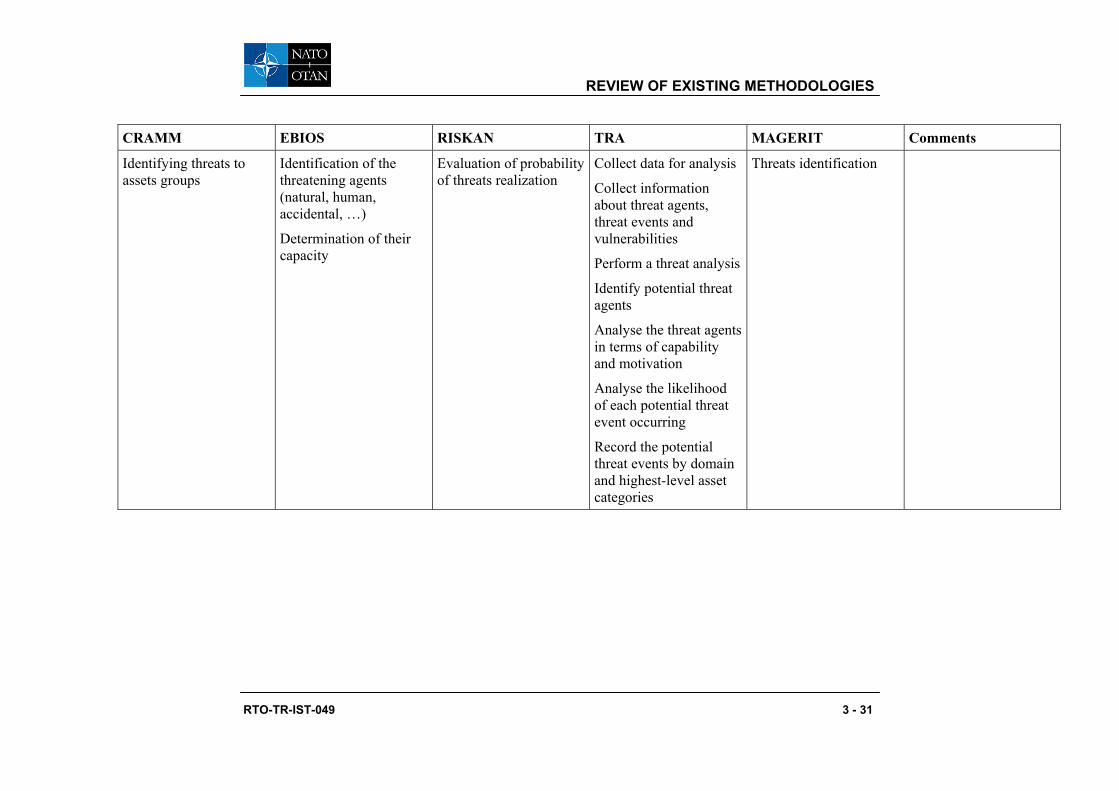
REVIEW OF EXISTING METHODOLOGIES
RTO-TR-IST-049 3 - 31
CRAMM EBIOS RISKAN TRA MAGERIT Comments
Identifying threats to assets groups
Identification of the threatening agents (natural, human, accidental, …)
Determination of their capacity
Evaluation of probability of threats realization
Collect data for analysis
Collect information about threat agents, threat events and vulnerabilities
Perform a threat analysis
Identify potential threat agents
Analyse the threat agents in terms of capability and motivation
Analyse the likelihood of each potential threat event occurring
Record the potential threat events by domain and highest-level asset categories
Threats identification

REVIEW OF EXISTING METHODOLOGIES
3 - 32 RTO-TR-IST-049
CRAMM EBIOS RISKAN TRA MAGERIT Comments
Assessing threats and vulnerabilities
Step 3.2: Vulnerabilities
For each selected attack method, identification of the system vulnerabilities which could allow their realization
Evaluation of vulnerability of assets to the threats
Perform a vulnerability analysis
Identify the vulnerabilities
Assign a vulnerability severity and exposure ratings
Determine the overall vulnerability ratings
For each domain, record the vulnerabilities with the highest exposure [or] severity rating, and the vulnerabilities with the highest overall ratings
Record safeguards that already protect assets from recorded vulnerabilities
There are no vulnerabilities identified in the MAGERIT method

REVIEW OF EXISTING METHODOLOGIES
RTO-TR-IST-049 3 - 33
CRAMM EBIOS RISKAN TRA MAGERIT Comments
Step 3.3: Threat formulation
A threat results from the combination of:
• A threatening agent (with a capacity)
• An attack method • A set of
vulnerabilities • The entities which
present those vulnerabilities
Perform a risk analysis
Identify possible threat scenarios

REVIEW OF EXISTING METHODOLOGIES
3 - 34 RTO-TR-IST-049
CRAMM EBIOS RISKAN TRA MAGERIT Comments
Calculating measures of risks
Step 4.1: Risks formulation
A risk results from the combination of:
• A threatening agent (with a capacity)
• An attack method • A set of
vulnerabilities • The entities which
present those vulnerabilities
• The threat capacity • The security needs • The impacts
Calculating of risk value for every asset and threat pair
Perform a risk analysis
Estimate the likelihood of each logical threat scenario occurring. Base the estimate on the likelihood the threat agent acting or the natural phenomenon occurring
Analyse the potential impact of each logical threat scenario
Assess the level of risk from each logical threat scenario. Likelihood of occurrence and potential impacts are considered
Risk analysis
Calculating measures of risks
Step 4.2: Security objectives
Risk management Step 5.1: Functional requirements
Assess system risks for acceptability
Comparative analysis can be displayed (with /without security measures)

REVIEW OF EXISTING METHODOLOGIES
RTO-TR-IST-049 3 - 35
This table shows that the different methods have a very similar structure with the following main steps:
• Background information;
• System modelling;
• Assets identification;
• Assets valuation;
• Threats analysis;
• Risk analysis; and
• Selection of counter measures.
3.3 ALTERNATIVE METHODS
All the above mentioned methodologies could be considered as exhaustive as they try to analyse all the threats on all assets of a given system. If we consider a very large system with many assets and a lot of potentials threats, themselves based on the existence of numbers of potential vulnerabilities, we arrive to a huge number of combinations. This result in a huge amount of tables and values which oversteps the human analysis capabilities and which are of little help to those in charge of the risk management part of the process. The use of tools are not a solution to this problem, as, on the contrary, they facilitate the possibility to combine automatically the items without any added value on the synthesis of the results.
To go round these reef methods based on attack trees tend to emerge for the analysis of large or complex systems. These methods are derived from the fault tree analysis used for reliability analysis (more information to be found in [W4]).
When using attack tree methods, the analysis is focused on a limited list of feared events which for NATO systems are generally easy to identify (loss of command / control capability, system destruction, …). Then an attack scenario is built with a level of detail increasing as the project moves from definition phase to realization or security evaluation.
The main drawback of this method is that it is not exhaustive. However, if the feared events are chosen carefully, the coverage can be large enough. Among the other drawbacks we can mention the lack of tools and the lack of experience on real systems.
The advantages are the facility to interpret the results due to the graphical representation and also the possible link with the methods and tools used by “red teams” people.
At this moment these methods are still in exploratory phases and it is then difficult to consider them as eligible as common NATO tools. However, we consider that they could be of real help in the future.

REVIEW OF EXISTING METHODOLOGIES
3 - 36 RTO-TR-IST-049

RTO-TR-IST-049 4 - 1
Chapter 4 – COMMON CRITERIA AND RISK ANALYSIS
In this section, emphasis has been put on the Common Criteria (CC) as being a potential element of a risk management framework, where risk analysis are performed though Threat and Risk Assessments (TRAs).
4.1 COMMON METHOD USING COMMON CRITERIA
The Common Criteria (CC) is an internationally recognized approach to security evaluation. It provides a set of criteria, which can be used to set requirements and to guide the development of IT security features within a specific product. These requirements serve as a guide for the development, procurement and evaluation of IT security features and products. Using a set of defined “assurance levels”, an accepted engineering standard can be applied to products under evaluation. The assurance levels are a graduated scale of documentation, and development and testing processes that appropriately grade the product’s security functions.
In contrast, the TRA is a formalized process used to determine the risks to Information Technology (IT) assets and provide recommendations to mitigate the risks to acceptable levels. A TRA generally has a broader scope of investigation and will include elements that do not lend themselves easily to modelling or quantitative analysis. This characteristic of a TRA is generally seen as a significant rationale for the failure of automated commercial risk management tools. A successful TRA tool must be able to leverage current knowledge bases using a well defined inference engine to correctly reason with the fine points of contemporary IT network architectures and their security technology. Such a tool has not been refined to the point where it can replace the human involvement in the Risk Management process.
In a previous study1, the preliminary findings show that the CC has the potential to relate to the following TRA aspects:
1) Structured terminology of controls;
2) Qualitative description of safeguards;
3) System architecture model;
4) Applicable threat model, including threat agent attributes (motivation, capability, opportunity, etc…) and threat scenarios;
5) Taxonomy of relevant vulnerabilities;
6) Classification scheme / sensitivity analysis of information assets;
7) Impact analysis of information assets, with respect to confidentiality, integrity and availability scenarios, and possibly mode of access;
8) Risk derivation model, the functional relation between risk and any of the above parameters;
9) Risk mitigation model linking safeguards and controls to threat scenarios; and
10) Risk acceptance of system operations is assessed based on CC evaluation results of security components of a system.
This concept needed some additional research to position the CC for use in a common framework for the NATO requirement. The CC is definitely a useful tool and can influence the risk management practice.
1 Common Methods For Security Risk Analysis, prepared for DRDC by Cinnabar Networks Inc., 22 December 2004.

COMMON CRITERIA AND RISK ANALYSIS
4 - 2 RTO-TR-IST-049
4.1.1 Similarities and Differences Between CC and TRA The TRA methodologies and tools have the goal of estimating the degree to which the controls or safeguards of an organization / system are sufficient to prevent harm or damage from threats directed at the information assets. On the other hand, the CC was created for the purpose of establishing the functional and assurance characteristics of IT products that are systems or parts of systems. Links between CC assurance and TRA risks are indirect and sometimes fuzzy. While the purposes differ, these activities are relevant to one another insomuch as:
1) The scope of CC evaluation is generally a sub-component of a TRA-scope: Inputs and outputs of a CC evaluation of a component of a system can be relevant to a TRA of the greater system;
2) CC evaluations are generally deeper than TRAs; and
3) Common activities are involved in both CC evaluation and TRA.
The CC evaluation is generally a much more detailed analysis, focuses on a sub-set of threats, entails extensive documentation, is a lengthy process and leads to significant costs. On the other hand, the TRA has usually a broader scope, may require extensive analysis but can be completed in a relatively short period of time at a reasonably low price. In addition, the generally smaller scope of the CC evaluation makes it impractical to undertake full CC evaluations of virtually any of the components of a system in support of a TRA. It is therefore unlikely that the two activities would ever be combined in a joint objective but rather one be supported by the other.
4.1.2 Using CC with TRA The focus of this section is on the application of the CC to TRA. The main areas in which this goal is achievable are as follows:
1) Threat mapping, where TRA threats are mapped to CC threats (note that there is no set of standard CC threats defined);
2) Safeguard mapping, where the TRA safeguard functionality are mapped to a set of CC SFRs;
3) EAL mapping of the TRA asset valuation and threat level of a specific threat scenario to an EAL (more specifically to an AVA component) required for safeguards mitigating the risk associated with the scenario;
4) Use of security assurance requirements (SARs) deliverables of a CC evaluation of a target subsystem of interest as inputs to the TRA; and/or
5) Use of Evaluation Technical Reports (ETRs). Section: Testing and Vulnerability Assessment.
The first three areas were introduced in a Canadian study published by the Communications Security Establishment (CSE) in 20022. They were introduced in the context of the definition of a multiple-entry point modification of a standardized TRA process (ITSG-04). The entry points are threat mapping and EAL mapping processes that link to the TRA, as well as a post-TRA entry point that performs safeguard mapping. This leading edge approach provides the missing assurance component to the TRA methodology. While it is beyond the scope of this document to describe more fully the details of this schema, it is representative of what can be gained from mapping CC concepts to the TRA process.
The last two areas above are much more direct input of CC-evaluation documentation into a system TRA. Risk-relevant information exists in specific CC SAR document sources and ETRs of components that have been successfully evaluated. However, these documents may be available only through direct negotiation
2 CSE – Threat and Risk Assessment Controls and Safeguards in Relation to The Common Criteria Report and
Recommendations, Version 1.1, 27 March 2002, Conducted by: Cinnabar Networks Inc.

COMMON CRITERIA AND RISK ANALYSIS
RTO-TR-IST-049 4 - 3
with the developer/vendor, presumably through nondisclosure agreement. Only in the case of the Security Target (ST) document, there is a general requirement for public disclosure, although this right can be withheld under appropriate conditions under the CC Mutual Recognition Agreement (MRA). A fundamental assumption is therefore that the documentation be available to the TRA team. The brief list of CC SAR documents that can serve as useful input to a TRA is shown in the table below.
Table 4-1: CC V 2.1 Documents Useful for TRA
CC Class CC Family Description Relevance as input to TRA
Vulnerability Analysis
AVA_VLA
Analyses TOE vulnerability to threats based on level of assurance
Primary: Highly relevant to TRA Vulnerability Analysis
Misuse Analysis
AVA_MSU
Analyzes misuse by a user prevented by the TOE, based on level of assurance
Primary: Highly relevant to TRA Vulnerability Analysis
Vulnerability Assessment
Covert Channel Analysis
AVA_CCA
Performs covert channel analysis based on assurance level
Primary: Highly relevant to TRA Vulnerability Analysis
Target of Evaluation (TOE) Description
ASE_DES
Basic description of TOE Secondary: Potentially useful information for system description and architectural analysis in the TRA
Security Environment
ASE_ENV
Threat analysis, policy analysis, environmental assumptions
Primary: Highly relevant to TRA threat scenarios and threat analysis
Security Target
IT Security Requirements
ASE_REQ
The evaluated TOE SFRs Primary: Highly relevant to TRA risk analysis
Coverage Analysis
ATE_COV
Demonstrates the coverage of SFRs by operational testing
Secondary: Potentially relevant as an evaluation of safeguard effectiveness
Testing
Depth Analysis
ATE_DPT
Demonstrates the depth of test cases by operational testing
Secondary: Potentially relevant as an evaluation of safeguard effectiveness
Other Audit, Cryptographic Functionality, Design Documentation, etc.
All SFRs
Describes TOE security functionality
Marginal: High level and detailed TOE information to clarify TRA
The AVA class deliverables provides indirect information on the vulnerabilities, misuses, and channels countered by the TOE and its environment. The TOE and its environment must mitigate all vulnerabilities, misuses and channels in the AVA analysis effectively. What does it mean? and What is the usefulness of the AVA class for a TRA vulnerability analysis?

COMMON CRITERIA AND RISK ANALYSIS
4 - 4 RTO-TR-IST-049
The meaning depends of what is performed in the AVA analysis and what is effective. First, the AVA analysis is dependent of the SFRs and SARs. Some vulnerability types may be discarded by the analysis because they do not depend on the TOE SFRs and SARs. For instance, if no covert channels analysis is required, no vulnerabilities related to covert channels are analysed; if no protection of the TSF data is required, no vulnerabilities related to TSF data are analyzed; and if no low level design information is available, no analysis is performed on the vulnerabilities introduced in the refinement process from the TOE high level design to the TOE implementation. Research needs to be pursued to get a clear understanding of these dependencies.
Second, the AVA analysis is also dependent of the TOE environment. So, it may be difficult to assert if a countered vulnerability is countered by the TOE, the TOE environment, or both. However, the ASE_ENV may help for this by listing environmental assumptions.
Third, the notion of effectiveness can be better expressed in the context of the new release of the CC (Version 3,0), where the AVA class has been modified. Effective means that the TOE and its environment mitigate all discovered threat scenarios in which threat agents have attack potential lower than or equal to a specific value, which value is defined in AVA_VAN. The set of discovered threat scenarios is a representative set of threat scenarios that involves vulnerabilities discovered through the AVA analysis.
From this it seems the AVA analysis would be useful for a TRA vulnerability analysis of a CC product in its intended environment if the vulnerabilities of interest are those exploitable by threat agents of attack potential lower than or equal to the value specified in AVA_VAN.
4.1.3 Protection Profile and TRA A protection profile (PP) is primarily an optional vehicle for user groups to publish evaluated security requirements for a specified class of products. PPs must be evaluated in the same manner that products are evaluated. Full compliance to the PP is mandatory if the PP compliance claim is made in the ST. There is no notion of partial compliance by the product.
While there is no formal connection between PP content and TRA processes, they do resemble the ST format closely, and many of the ST mappings to TRA described above would apply equally to PPs. Generally, however, the product ST duplicates this information and further instantiates those product-specific requirements in the PP that are unspecified (i.e., left as refinements, assignments, etc.). Therefore, the PP stands as a relatively generic requirement. As a catalogue of threats, the PP can play a significant role in threat analysis, specifying what type of protection is expected by informed users from a class of products. It is possible that no products on the market actually satisfy an evaluated PP. This may suggest caution on the use of PPs in a TRA safeguard selection.
4.2 CRITICAL ASPECTS OF COMMON CRITERIA EVALUATION
The CC in general is based on the notion of evaluating a given product, be it a network, operating system, database, etc., irrespective of the environment. This focus is further enforced in the notion of the boundary of evaluation of the Target of Evaluation (TOE). While much of this supports the practical process of evaluating a commercial product, it is not particularly well suited to the needs of risk analysis. The following critical observations further expand on this theme:
1) Although the Common Criteria does expect a vendor to indicate the type of environment the product should be used in, it discusses environments in a broad manner and leaves the level of detail to the developer discretion.

COMMON CRITERIA AND RISK ANALYSIS
RTO-TR-IST-049 4 - 5
2) Many products are evaluated to co-exist within specific environment. Deploying them in other environments results in the invalidation of the evaluation. This characteristic places the onus on the part of the customer to check statements in the Security Target (ST) regarding Environmental Assumptions and Environmental Security Policy against actual deployment in order to obtain a sense of fitness for use. Such decisions are beyond the control or scope of the CC evaluation.
3) Although the CC is a formalized methodology, it may be inconsistently applied across the CC community. A product evaluated under two separate laboratories would be treated to differing levels of examination. The Criteria does not enforce a methodology upon the laboratories and therefore there is no current way to ensure evaluations are truly equitable. Nevertheless, the Common Evaluation Methodology (CEM) CC document provides a framework for the processes to be performed by these methodologies. Reciprocity agreements, such as the Mutual Recognition Agreement (MRA) accept evaluations from other nations but are not an indication of agreement to the methods used.
4) The CC focuses on how well (i.e., trustworthy) the functionality is implemented within a given product. It does not provide any direct answers as to the efficacy of said product within a given environment. As noted above, CC vulnerability analysis must demonstrate complete coverage by the product and its environment, without residual risk, but only for a set of vulnerabilities dependent of the SFRs and SARS and of the attack potential. Nothing is said with respect to vulnerabilities not related to SFRs and SARs. This approach is at variance with the more general notion of vulnerability used in TRA practice, and requires further analysis on the part of the TRA team to find potentially relevant vulnerabilities not covered in AVA_VLA (or AVA_VAN) documentation.
5) An evaluation is based on the product itself. Little consideration is given as to the type of information processed by the product. This lack of information identification is a major point separating CC evaluation methodology from that of TRA. There is no explicit classification of data process or statement of sensitivity in the CC process. In the end, if the product obtains a successful evaluation, it is solely on the basis of whether or not it met the minimum requirements for functionality and trust.
6) There is no assurance provided that two evaluated products can be comparable. Differing methods of evaluation can and do result in differences in whether or not a given product met a given requirement. Although reciprocity has been gained on a number of fronts, for some applications the US, for example, will not accept non-North American evaluations.
7) While the original goal of harmonization of security product evaluation has been actively pursued in the development of the CC, constant forces of a protectionist or exclusionary tendency exist among the signatory nations that favour evaluations of one or more nations over others. These tendencies are not always identified as such, nor is there an effective global mechanism to counteract them. Another continuing barrier to increased harmonization is the lack of progress in achieving an extension of the MRA to beyond-EAL4 evaluations. Recent developments in the US and elsewhere indicate that this is an unlikely expectation in the near future.
8) The final issue with CC evaluations is the time required for completion of the evaluation. Even for rudimentary evaluations the time taken to evaluate a product is excessive. An EAL-3 or 4 product may well have been under evaluation for two or more years. Hence, the product will be two or more revisions away from the currently commercial available version. In the commercial world the unforeseen length of the evaluation is a direct cost overrun. This timeliness issue continues to plague evaluations and has led to the cancellation of otherwise viable CC evaluation projects.
A major consideration in the decision to pursue CC evaluation is the total cost of the evaluation, both in monetary terms and in terms of developer time and effort. The direct cost of CC evaluation is a significant factor in the decision by organizations to pursue either a PP or product evaluation. The significant costs

COMMON CRITERIA AND RISK ANALYSIS
4 - 6 RTO-TR-IST-049
are mostly due to the large volume of documentation that must be produced by the developer, evaluated by the CC laboratory and further corroborated by extensive testing. These costs are expected to be proportional to the assurance level being claimed by the developer, because more evaluation documentation is required as the EAL increases. Further costs are related to higher assurance, such as increased complexity of site visitation evaluation tasks, testing requirements, and the evaluation of formal modeling, specification and design that is mandated at EAL5 – EAL7. In addition, certain technologies may require more extensive evaluation and testing costs than others, e.g., biometrics, cryptography, complex protection systems.
Cost is not a controlled or fixed item, and is largely the result of open market competition on a country-by-country and laboratory-by-laboratory basis. Some countries provide financial support to laboratories under their CC Schema. In North America, an EAL2 evaluation may cost several hundred thousand dollars. Funding of such projects must be justified either by developer-perceived increased market share or level of support by funding agencies. The level of assurance required in many currently evaluated PPs is another cost factor. In many cases commercial developers face a significant technical challenge in justifying the development of products that satisfy particular PPs. In some cases, government-sanctioned PPs have attained the status of technical IT standards for entry into government and military markets. When based on a purely financial return on investment, CC evaluation in a competitive market remains a business risk issue.
While the above analysis provides some of the predominantly negative aspects of the CC in general, there are positive reasons to consider the use of CC concepts in a TRA context:
1) It is possible to consider a given existing product evaluation within a TRA. A product with an evaluation may be more trustworthy than one that has not been evaluated. Two similar products, for example two UNIX-based operating systems, can be fairly ranked on whether or not they have been evaluated. However, the usefulness of the lowest assurance levels has come into question. The fact that a product has undergone EAL 1 or 2 may not be of any greater intrinsic value than a product that has gone through a rigorous quality assurance process from a reputable firm. The jury remains out on that issue;
2) The most advantageous elements of the Common Criteria remain the taxonomy of functionality and assurance so that products can, more or less, be evaluated to similar security standards. The common grouping of functionality and the notion of interdependency between specific functionality components is something that would be beneficial to introduce into a formalized and automated TRA methodology;
3) A TRA can be augmented with a certain assurance level by using the CC threats and adding a non-CC level, by mapping the TRA safeguard functionality to CC SFRs (or SARs), or mapping the TRA asset valuation and threat level of a specific threat scenario to an evaluation assurance level (EAL); and
4) The use of security assurance requirements (SARs) deliverables of a CC evaluation of a target subsystem of interest as inputs to the TRA.
4.2.1 CC and TRA Summary The use of the CC in TRA methodologies and tools is still at an early stage. This section has indicated some sources of information produced by a CC evaluation that would be relevant, to varying degrees, in a TRA context. The role of PPs has been discussed as a generic class specification in much the same way. The mapping of CC to IT security framework shows weakness in the common framework approach. Due to excessive expense and time required, it would not be recommended to pursue CC evaluation of a product simply as part of a TRA. The practical methods of applying CC technology to the TRA process are found to be:

COMMON CRITERIA AND RISK ANALYSIS
RTO-TR-IST-049 4 - 7
1) The use of the common terminology, taxonomic and definitional structure of the CC to organize TRA methods and tools, and
2) The use of component CC evaluation deliverables as information sources in the analysis of threats, vulnerabilities, environmental assumptions and related security functional information.
The CC methodology could be leveraged for involvement in the TRA process by combining CC evaluated components into a higher order system, which encompasses (in part or in entirety) the scope of the TRA engagement. However, a method by which CC evaluated products can be combined in such a way as to retain the usefulness of their assurance level ratings is needed. Two such methods were proposed, but the need for extra research in this area is clearly indicated. Specifically, methods are needed which will allow such an analysis to be:
1) Effective in the face of emergent behaviour of such a composed system; and
2) Efficient in the reduction of manual effort so as to justify leveraging the work performed in the CC component evaluation.
In the absence of methods by which these goals can be achieved, the use of composed system to assess the risk level posed by a system under evaluation cannot be recommended at this time. Annex A provides an overview of the use of the composed system model as a potential mechanism by which the Common Criteria approach can be leveraged to be of use in performing TRA.
Recommendation # 1 The common methodology to risk management should leverage the CC evaluation of components and possibly use its structure terminology but should not rely on the CC framework as the model for the NATO common TRA framework.
4.3 SECURITY REQUIREMENTS AND CC
Risk analysis methods and tools often include the identification of security requirements that can be proposed to counter the identified risk. It seems then useful to rely on the part 2 of the CC for this work. This means:
• Using at a minimum the security functional class names (security audit, user data protection, security management, …) to classify the security requirements.
• If possible, use the CC components when writing the security requirements. This could save time by relying on the CC efforts to produce relevant requirements. This is also a guarantee that requirements issued from different tools or methods will be comparable.
At the moment, there is no satisfactory tool to select automatically security requirements consistent with the estimated level of risk. This could be a research area given that there will always be a need for a human arbitration as many other factors have to be taken into account such as the cost, the environment, the operational constraints, …

COMMON CRITERIA AND RISK ANALYSIS
4 - 8 RTO-TR-IST-049

RTO-TR-IST-049 5 - 1
Chapter 5 – RISK ANALYSIS TOOLS
5.1 EXISTING TOOLS
5.1.1 EBIOS Tool The EBIOS tool is available on the DCSSI web site: http://www.ssi.gouv.fr/document/docs/EBIOS/ ebios.html.
The software highly helps users to:
• Record results, to produce tables and to make some calculations automatically;
• Produce outputs based on different templates: study report, security objectives form, synthesis, security policy, strategic note for security, SSRS, security targets, …;
• Learn intuitively how to use the software with a self-training module (case study named @rchimed included); and
• Customize knowledge bases:constraints, threats, vulnerabilities, metrics, security requirements…
This is an Opensource Software (UML, Java, XML): the software and its source code are free, easily available ([email protected]) and improvable if a return to DCSSI is done.
5.1.2 CRAMM The CRAMM software is distributed by a UK company called Insight Consulting. An interactive walkthrough presentation is available for free (www.insight.co.uk).
NB: the NC3A has bought a CRAMM software. Contact: J-L AUBOIN, NC3A ACQ INFOSEC, +32 2 707 8238.
NATO has 20 to 25 software licenses.
5.1.3 RISKAN The RISKAN tool is a Microsoft Excel ® based product. It is distributed by T-Soft Novodvorská 1010/14, 142 01, Praha 4 ([email protected], http://www.tsoft.cz).
5.1.4 PILAR / EAR The product is available on a commercial basis. A read only version can be downloaded from: http://www.ar-tools.com/en/dowload/index.html.
The product can be customised by the user. The structure of all the tables (XML files) is included in the documentation.
5.1.5 Comparative Analysis The analysis will focus on CRAMM, PILAR and EBIOS, the three tools which have been analysed in detail by the WG.

RISK ANALYSIS TOOLS
5 - 2 RTO-TR-IST-049
Table 5-1: Comparative Analysis
+ -
CRAMM
Ease of use
Very large CM database
High level threats
No access to databases and algorithms
Only one type of system modelling
No identification of system vulnerabilities
EBIOS Open source software
Configurable databases
User interface
No default system modelling
PILAR / EAR Configurable databases
Hierarchical representation
Graphical outputs
Complete documentation
Risk management module included
Confusing strategy for managing vulnerabilities (the word vulnerability is not used)
General comments can be issued on these tools:
• As stated in Chapter 3.3 Alternative methods there is a risk of combinatory explosion when used on large systems.
• These tools should be used only by trained and skilled experts as they are to be considered as a help but cannot replace the human experience. The use of such tools by unskilled people can lead to irrelevant results.

RTO-TR-IST-049 6 - 1
Chapter 6 – DEFINITION OF A COMMON METHODOLOGY
It is always a good practice to go back to the basics and examine what are the components of risk management and where commonality may exist between different risk identification exercises. In this section, the analysts attempt to present some of the standard ways in which risk analysis is conducted. The result is a proposed common TRA framework.
6.1 THE DIFFERENT COMPONENTS OF RISK ANALYSIS
The traditional risk analysis framework is well established, although some methodologies provide emphasis on different risk factors. The Canadian ITSG-04 is more a threat and asset centric methodology. The NIST 800-30 is more vulnerability centric with little insight to confidentiality, integrity and availability. One must agree that even though the outcome, the risk value, is common to all methods, considerable variation exists in terms of interpretation of the basic terms and the general process model. Common language between methodologies is lacking, resulting in limitation in the development of a common framework. If a common approach is the ultimate goal, all stakeholders should agree on the basic components of a TRA. Following the functional description of the risk, R=ƒ (AVal, T, V), the components of a TRA are (definition from ITSG-04):
1) Assets Identification or the Statement of Sensitivity (SoS): A description of the confidentiality, integrity and availability requirements associated with the information or assets stored or processed in or transmitted by an IT system;
2) Threat Assessment: An evaluation of threat agent characteristics including resources, motivation, intent, capability, opportunity, likelihood and consequence of acts that could place sensitive information and assets at risk;
3) Vulnerability Assessment: An evaluation of the vulnerabilities of an IT component, program or system to determine if the controls in place are sufficient to address security issues that could impact the confidentiality, integrity, or availability of the system assets; and other types of impact are possible such as costs; and
4) Risk Assessment: An evaluation of risk based on threat assessment information, the effectiveness of existing and proposed security safeguards, the likelihood of system vulnerabilities being exploited and the consequences of the associated compromise to system assets.
[One of the recommendations from the previous risk management study1 was to ensure a common language or common terminology is used in the common risk management framework]. The NATO working group agreed on a NATO vocabulary. However, for this study, the NATO glossary was not made available to the analysts. For that reason, it is assumed that the selection of terminology was agreed upon, which on its own, is a significant step towards a common framework. Another fundamental assumption is that regardless of the risk management methodology, the four basic steps described above are an integral part of the common framework.
6.2 GENERIC RISK ASSESSMENT FRAMEWORK
The four basic TRA components can be expanded upon to develop a generic functional framework. The previous study suggested a general functional framework for either manual or automated risk assessment. The rational behind this approach is to provide a basis for commonality, clearly define the inputs and outputs to each TRA phases to minimize potential factual error and to allow insight into where
1 Common Methods For Security Risk Analysis, prepared for DRDC by Cinnabar Networks Inc., 22 December 2004.

DEFINITION OF A COMMON METHODOLOGY
6 - 2 RTO-TR-IST-049
automation (or partial automation) could take place (blue). The outputs or deliverables are often combined in a single report. The generic functional framework would comprise the following elements.
Table 6-1: Generic Risk Assessment Framework
Function Description Inputs Outputs
Business Model The organization business model is defined and understood.
Legislation
Interviews
Observations
Success Factors
Mission Statement
Business Requirements
User Requirements
Target Risk Level
TRA Scope
System Architecture Analysis
System Architecture is analyzed and assessed as a basis for asset location analysis and vulnerability analysis.
Interviews
Documentation
Observations
System Development Life Cycle Phase
TRA Scope
System Architecture
System Description
Concept of Operation
Information Flow Description
User Community
Refined TRA Scope
Asset Classification, Impact Analysis and Injury Test
Information assets are identified, described, classified by sensitivity.
System Description
Interviews – Directed questions
Documentation
Observations
Qualitative Rating Description
Asset Profiles
Statement of Sensitivity
Sensitivity Impact Statement
Requirements for other Security Services
Threat Assessment Threat agents are identified by class characteristics and behavioural analysis; Threat Scenarios are constructed using simple tabular or more complex, e.g., attack tree-based, Bayesian, or causal net-based representations.
Interviews
Documentation
Observations
Architecture
Asset Profiles
Expert Knowledge
Qualitative Rating Description
Threat Agents Table
Threat Scenarios Table

DEFINITION OF A COMMON METHODOLOGY
RTO-TR-IST-049 6 - 3
Function Description Inputs Outputs
Vulnerability Assessment
System vulnerabilities are identified and assessed; relationship to threat scenarios identified using simple tabular or tree-based representations.
Interviews
Documentation
Observations
Architecture
Threat Scenarios
Expert Knowledge
Vulnerability Categories
Vulnerability Table
Safeguard Analysis Existing safeguards are identified and assessed for strength; relationship to vulnerabilities identified.
Interviews
Documentation
Observations
Architecture
Vulnerability Table
Expert Knowledge
Safeguard Categories
Initial Safeguard Tables
Risk Assessment Existing risk is assessed by threat scenario: associated vulnerabilities, safeguards and threat agent characteristics functionally determine an effective threat level that reflects current mitigation; Statement of Sensitivity and threat levels provide inputs of risk level determination.
Statement of Sensitivity
Threat Agents Table
Threat Scenarios Table
Vulnerability Table
Safeguard Tables
Qualitative Rating Description
Risk Mitigation Strategy
Initial Risk Assessment
Additional Safeguard Recommendations
New Safeguards are identified and assessed for strength; relationship to vulnerabilities and threat scenarios identified, indicating effective risk mitigation rationale; strategic deployment of new safeguards indicated.
Safeguard Categories
Initial Safeguard Tables
Architecture
Vulnerability Table
Expert Knowledge
Enhanced Safeguard Tables
Residual Risk Assessment
As in Risk Analysis above, but with the Enhanced Safeguard Tables, to show the effect of the mitigation strategy of adding new safeguards.
Statement of Sensitivity
Threat agents Table
Threat Scenarios Table
Vulnerability Table
Enhanced Safeguard tables
Recommendations
Residual Risk Assessment

DEFINITION OF A COMMON METHODOLOGY
6 - 4 RTO-TR-IST-049
Function Description Inputs Outputs
Remediation Plan A follow up plan to ensure recommendations are addressed in due time and the risk is monitored upon implementation of mitigating strategy.
Recommendations
Enhanced Safeguard Tables
Timeline
Team Responsibility
Prioritization of Recommendations
Remediation Plan
Final Report A comprehensive and useful TRA report to document findings of the analysis and to provide inputs to other risk management activities.
SoS
Threat Assessment
Vulnerability Assessment
Risk Assessment
Prioritization of Recommendations
Remediation Plan
TRA Report
Executive Summary
Certification Process
This generic framework is uniquely developed from the melding of different TRA methodologies to address weaknesses that were observed in the TRA process. It covers all phases and elements of a TRA leaving no undue facets for potential inaccuracy or omission. This method is more streamlined resulting in a more accurate analysis and precise risk ratings.
Further discussions are provided in the next sections on automation, standardization and commonality. The Canadian contribution would give precedence to risk management work using these innovative concepts.

RTO-TR-IST-049 7 - 1
Chapter 7 – RECOMMENDATIONS
7.1 DYNAMIC RISK ANALYSIS
With the new concept of operations outlined in the NNEC or NCW concepts there is a need for dynamic risk assessment. Dynamic risk assessment refers to a risk assessment that can be updated quickly as the system being assessed changes. These changes for example may be due to:
• The operational threat level; • The mission type (peace support operation, humanitarian operation, high intensity fight, …); • The incremental system development; and • The deployment phase.
In the current and near-term situation, the mission network is centrally managed, with the participating nations bringing their own equipment not attached to their own national networks. In the transition to the NEC, the mission networks will become less centralized and more of a federation of networks – with consequent impact on responsibility for dynamic risk assessment and deployment of tools supporting dynamic risk assessment.
Another aspect of dynamic risk analysis concerns the feedback between vulnerabilities detection tools and the results of the initial risk analysis which identified potential and generally high level vulnerabilities.
7.2 INFORMATION EXCHANGE REQUIREMENTS
7.2.1 For Systems Interconnections When two CIS are required to be interconnected to exchange information, an SISRS (or national equivalent(s)) should be formulated, which forms the basis of a security agreement between the two CIS operating authorities (or between the two system managers) and the two security approval or accreditation authorities. SISRS, relies on risk analysis performed by one party, and is approved by both parties.
It is then of major importance that the results of risk analysis can be exchanged and understood by both parties.
7.2.2 To Update a Common Threat and Vulnerability Repository Having common profiles for system assets, threats and vulnerabilities will greatly facilitate the sharing of this information and could permit the creation of a common and shared threat and vulnerability repository. Annex B and C give examples of such profiles for threats and assets.
7.2.3 Within a Coalition In attached coalition networks, a nation can maintain and control the scope of the dynamic risk assessment on their domain of control. This would allow them to limit network information disclosure if necessary by national policy.
The NNEC foresees all dynamic risk assessment tools under national control only. In that scenario and in the phases leading up to it, national systems can run their own dynamic risk assessments and pass the output to be correlated with a central tool, or to the tool of another partner, as illustrated in the below figures. Alternatively or in parallel, the components could send information straight to another partner’s tool depending on the architecture or policy.

RECOMMENDATIONS
7 - 2 RTO-TR-IST-049
Figure 7-1: DRA, Alternative Architectures for Coalitions.

RECOMMENDATIONS
RTO-TR-IST-049 7 - 3
The final objective is to obtain a “Consolidated Information Assurance Picture”. The features of this CIAP as well as the nature of the exchanges between the different components are still to be defined by the Nations.
7.3 PROPOSED EVOLUTIONS OF EXISTING METHODS AND TOOLS
To help interoperability between risk analysis performed using different methods and to help the TRA users a set of additional functionalities have been identified.
• Methods should be based on documented models (e.g. impact model, risk model, threat model, threat agent model, entity model, entity relationship model, vulnerabilities model). It should be possible for a user to improve or to replace these models. This implies the modularity of the methods.
• Methods should used a technical repository for assets, threats and vulnerabilities. The mid term objective should be to use the common repository described in 7.2.2.
• Methods should be quantitative instead of qualitative.
• Methods should use the principle of refinement (more depth) to reuse and improve TRAs.
• Methods should allow reusability: it should be possible to reuse the result of a previous risk analysis on a system, sub system or component and to include these results in a new analysis.
• Methods should allow to reuse of the vulnerabilities analysis done during a product evaluation (CC, FIPS 140-1) or a system security testing.(vulnerabilities scan, IDS, …).
• Tools should be able to implement accurately the methods, to interface with external repositories, and to offer a user friendly interface.
• When performing risk assessment or when identifying countermeasures, tools shall be able to take into account the standard NATO security measures (physical, procedural) and the NATO technical security requirements.
• Tools should offer functionalities to conduct high level risk analysis in a time frame coherent with the new needs for system deployment and accreditation. Detailed risk analysis should be refined from these high levels ones if necessary.
• Tools should offer simulation capabilities or at a minimum extended “What if” functions, in order, for example, to select the most appropriate countermeasure or to identify the impact of a change in threat level, in system architecture / configuration.
7.4 FOLLOW ON ACTIVITIES
7.4.1 Within RTO/IST An IST workgroup should streamline the Consolidated Information Assurance Picture and Dynamic Risk Assessment concepts, which are two key capabilities listed in the NATO Network Enable Capability (NNEC) Information Assurance roadmap to be published in early 2007 by ACT.
The Consolidated Information Assurance Picture can be seen as a first step in Cyber Command and Control giving operators visibility on what is currently going on in the Communications Information System (CIS). This will enable the operators to make proper decisions on what actions to take.
The Dynamic Risk Assessment (DRA) is to an additional component in the Cyber Command and Control Capability. The DRA tool will be able to feedback to the sensors based on threat levels and policy.

RECOMMENDATIONS
7 - 4 RTO-TR-IST-049
Actually no formal concept is recognized, no clear methods are formalised and no empiric or commercial tools seem to exist. Nevertheless, these two needs are explicitly identified and required insomuch capabilities at mid and long term for the NATO Network Enable Capability.
7.4.2 Within Other NATO Entities This IST report should then be transmitted to the NATO Computer Incident Response Capability (NCIRC) and the NATO Security Accreditation Board (NSAB), in support of their current missions.
The output of this group and more precisely the 7.3 should be used for the selection and procurement of risk analysis tools in support of the Capability Package CP0A0155 for Electronic Information Security Services (called INFOSEC CP 155).
NC3A, implementing the ACT Experimental and Scientific Program of Work (EPOW and SPOW) should consider this report and take inspiration in its production. Moreover, NC3A is encouraged to continue its effort to liaise with IST forums on following activities in this area and to report back (on behave ACT) on the progress done within the EPOw and SPOW.
The INFOSEC Subcommittee (number 4), belonging to the NATO C3 Board Substructure, should be presented some IST results to raise the awareness of the operational and technical INFOSEC community, on the work done by scientific INFOSEC community.

RTO-TR-IST-049 A - 1
Annex A – COMPOSED SYSTEMS
This section provides an overview of the use of the composed system model as a potential mechanism by which the Common Criteria approach can be leveraged to be of use in performing TRA. This model is used to combine many CC evaluated components into a composed system, which more accurately reflects the scope of a TRA engagement. This approach is generally referred to in the CC as a system-level evaluation. Examples of how assurance levels can be derived for a composed system are provided and the challenges of using this approach are described.
A.1 COMPOSED SYSTEMS
A logical view on these complementary, yet dissimilar, approaches to IT security as it pertains to risk management is to determine how the strengths of each can be combined into a more complete solution and, simultaneously, reduce the effort to conduct risk analysis by allowing one effort to build on the other. This approach would entail combining the component-based, requirements-oriented quantitative view of the Common Criteria with the holistic approach espoused by the TRA methodologies. One method to perform such an amalgamation of approaches is to view a system as a sum of components, what is referred to in IT circles as a composed system.
The concept of composed systems dates back to early days of IT architecture development and has been employed in various guises. Most notably in software development circles, the composite design pattern1 is frequently used to allow clients to treat objects or compositions of objects uniformly in a hierarchical representation. A composed system may be designed with the purpose of driving specific properties for a collection of constituent components, or the composite properties of a collection of components may be viewed in a systemic fashion. From this specific context, it is possible to apply a TRA methodology to CC evaluated component, by examining the composition of such components as an equivalent and uniform entity.
A composed system will view all constituent components as a single system and strive to optimize the system as a whole. Within the context of integrating the CC and TRA approaches, the constituent components are CC evaluated products, and optimization is the reduction of risk to an acceptable level across the entire composed system. There are immediate concerns with such an approach:
1) Lack of Common Authority: From a system management perspective, simply choosing to view a collection of components as a system does not mean that there will be agreement among the respective authorities for these components as to the methods by which risk will be reduced across the system as a whole. This difference of opinion among key stakeholders is primarily a project management issue and is often encountered in the TRA process. Nevertheless, there is reason to expect that this difficulty will be greater under this model, given that various stakeholders will have more investment (time, prestige) in maintaining the assurance level for their own component;
2) Local versus Global Optimization: A concern in any composed system approach is that the optimization for the system as a whole will be achieved at the expense of the optimization of some individual components. This concern may be less significant since a fundamental assumption of the composition and risk analysis approach should be that no changes to the environment can jeopardize the assurance level of any given component. Within the bounds of this constraint, however, the changes to the system can be recommended so as to minimize the
1 Eric Gamma, Richard Helm, Ralph Johnson, John Vlissides, Design Patterns, Addison-Wesley Professional Computing
Seriesm, 1995, pg. 163.

ANNEX A – COMPOSED SYSTEMS
A - 2 RTO-TR-IST-049
risk level without compromising the assurance level of the continuant parts. It is, in fact, a generally accepted principle that a system cannot be optimized by optimizing its component parts, but only through the optimization of the solution itself. This principle provides further evidence that system-level management is needed to utilize the composed system model properly; and
3) Redundancy: Similar to the previous concern, the fact that individual elements of the composed system cannot be altered in such a way that the assurance level of these components is invalidated, it is likely that the composed system will contain security safeguard redundancies. The mere presence of redundant safeguards in a risk analysis environment is often raised as vulnerability. One can speculate that a redundant safeguard brings vagueness to the manner in which information assets are protected. Also, there is a concern that security policy decisions may be applied inconsistently if there are multiple paths to access system/information assets. Redundant safeguards also have a limiting effect on supporting system security activities such as auditing and maintenance.
However, the most fundamental concern is how CC evaluated components can be aggregated into a composed system in such a manner that it is possible to make a statement about the security level of the system itself. This discussion is limited exclusively to the notion of how an “assurance level” (or equivalent) can be assigned to the composed system. It is recognized that there will have to be architectural standards by which these components can be combined to form the composed system.
In the paper on Composable Trusted Systems2, Lee [et al.] suggests two methods for generating an assurance level for a composed system. Each method is described below.
A.2 VERTICAL ASSURANCE This approach for composability generates a cumulative assurance value from the lowest level component to the highest (systemic) level. Each level of the composition would be treated as separate and independent in terms of it ability to meet the required level of assurance. At each composite level, it is possible to determine if the policy requirements are met by the implementation details at the next level. If policy requirements are met at each level within the composed system, a chain of belief is formed which provides assurance that the composed system is in compliance with policy requirements at a systemic level.
In presenting this approach, Lee [et al.] provided a mechanism for forming a metric to calculate assurance and expressed, at each level, a probability of loss of assurance for a given policy statement. These level-based policies were then aggregated to express a Cumulative Probability for Loss of Assurance at the systemic level. It was recognized that there were several limitations to this approach including:
1) The difficultly in expressing policy adherence in terms of probabilities; 2) The loss of information relating to the fact that adherence is expressed as a binary success/failure,
rather than providing insight into the degree of failure; and 3) Once expressed as a cumulative loss of assurance, any policy violation cannot be traced back to a
specific policy level objective.
A.3 STRUCTURAL ASSURANCE This method of composing assurance for a composed system takes a simpler view. Essentially, all properties of a composed system are assumed to be a union of the properties of the constituent parts. From this description, there are two scenarios which can be described in terms of how components will interact:
2 E.S. Lee, B.W. Thompson, P.I.P. Boulton, R.E. Soper, Composable Trusted Systems, Technical Report CSRI-272, May 31,
1992.

ANNEX A – COMPOSED SYSTEMS
RTO-TR-IST-049 A - 3
1) Components are isolated so there is no interaction defined in the specification; and
2) Interactions are planned, designed and implemented as part of the specification.
The first scenario implies that deviations from the expected behaviour of a given component will not affect the behaviour or assurance level of other component functions or properties within the composed system. In this way, each component can be treated as having independent properties and the properties can be accumulated and analyzed independently. This view is contrary to several fields of systemic research including complexity theory and patterns of emergent behaviour.
When analyzing a composed system using the structured assurance method it is necessary to take into account the degree to which a failed component or function will interfere with its neighbouring components. An analogy can be made with a gearing mechanism where a slightly misadjusted gear may have a much more significant impact on the gears to which it is linked, potentially resulting in a complete systemic failure. In his paper, Lee [et al.] provides a more specific example of memory corruption in software modules resulting in a complete systemic fault. This concern can be ameliorated through the use of barriers, included as part of the specification, to effectively isolate components and reduce interference.
The second scenario, in which interactions are well defined in the specification using controls to keep the interaction within the bounds set by the policy specification, is not exempt from the structured analysis of intra-component interaction. However, the overall analysis is more complex in that the designed interactions must be scrutinized to ensure that they are in compliance with the defined policy objectives (e.g. channel integrity). Techniques such as sensitivity analysis are recommended for this form of evaluation in which the input from a component must be treated as suspect. Automation tools exist which can assist with this analysis, both with software and hardware components.
In essence this technique requires an impact analysis between each component in the composed system to determine the sensitivity of the system to catastrophic failure due to inherent limitations in the composed system itself. The level of effort to perform such an analysis grows significantly as more components are introduced to the system. It should be noted that when two composed systems are themselves to be merged into a higher order composite system, the structured approach would require that the composed system be first decomposed and an analysis performed on each of the lowest level components. This requirement is due to the fact that there may not be inter-system interference in either of the composed systems, but interference, at a component level, may exist when the composed systems are combined.
A.4 A NOTE ON COMPLEXITY THEORY
“A system that is not explicitly described by the behaviour of the components of the system, and is therefore unexpected to a designer or observer can be deemed to have emergent properties.”
The goal of the CC is to ensure that a system has been designed, implemented and documented according to policy and specifications. However, an alternate view on the process is that an evaluator is trying to disprove the negative hypothesis; that the system has not been implemented according to the specifications. With this assumption, it can be extrapolated that the system is going to display unexpected behaviour. From this statement, one can add that such a system will have emergent properties.
In the context of a composed system, the combining of two such systems (or components) will create not only a more complicated system in the general sense of the word, but also a complex system. Behaviours and patterns emerge in complex systems as a result of the patterns of relationship between the components. There are generally accepted properties of complex systems that define the impact emergent behaviour will have in a composed system including the following:

ANNEX A – COMPOSED SYSTEMS
A - 4 RTO-TR-IST-049
1) There are rarely simple cause and effect relationships between elements. A small deviation in a single component may have a large impact at the system level through the interaction with neighbouring components;
2) Emergent behaviour often encompasses feedback (or dampening) potentially amplifying the initial deviation into a system level fault; and
3) Decomposition of the emergent behaviour is extremely difficult based on observation of the behaviour itself. Debugging a system that is displaying emergent properties is extremely difficult since the actions at the system level cannot be explained and the components on their own cannot display the behaviour.

RTO-TR-IST-049 B - 1
Annex B – EXAMPLES OF ATTACK METHODS (FROM EBIOS)
A C I
1 – Physical Damage
01 – FIRE x x
02 – WATER DAMAGE x x
03 – POLLUTION x x
04 – MAJOR ACCIDENT x x
05 – DESTRUCTION OF EQUIPMENT OR MEDIA x x
2 – Natural Events
06 – CLIMATIC PHENOMENON x x
07 – SEISMIC PHENOMENON x x
08 – VOLCANIC PHENOMENON x x
09 – METEOROLOGICAL PHENOMENON x x
10 – FLOOD x x
3 – Loss of Essential Services
11 – FAILURE OF AIR-CONDITIONING x
12 – LOSS OF POWER SUPPLY x
13 – FAILURE OF TELECOMMUNICATION EQUIPMENT x
4 – Disturbance Due to Radiation
14 – ELECTROMAGNETIC RADIATION x x
15 – THERMAL RADIATION x x
16 – ELECTROMAGNETIC PULSES x x
5 – Compromise of Information
17 – INTERCEPTION OF COMPROMISING INTERFERENCE SIGNALS
x
18 – REMOTE SPYING x x x
19 – EAVESDROPPING x
20 – THEFT OF MEDIA OR DOCUMENTS x
21 – THEFT OF EQUIPMENT x x
22 – RETRIEVAL OF RECYCLED OR DISCARDED MEDIA x
23 – DISCLOSURE x
24 – DATA FROM UNTRUSTWORTHY SOURCES x x
25 – TAMPERING WITH HARDWARE x

ANNEX B – EXAMPLES OF ATTACK METHODS (FROM EBIOS)
B - 2 RTO-TR-IST-049
A C I
26 – TAMPERING WITH SOFTWARE x x x
27 – POSITION DETECTION x
6 – Technical Failures
28 – EQUIPMENT FAILURE x
29 – EQUIPMENT MALFUNCTION x
30 – SATURATION OF THE INFORMATION SYSTEM x
31 – SOFTWARE MALFUNCTION x x
32 – BREACH OF INFORMATION SYSTEM MAINTAINABILITY
x
7 – Unauthorised Actions
33 – UNAUTHORISED USE OF EQUIPMENT x x x
34 – FRAUDULENT COPYING OF SOFTWARE x
35 – USE OF COUNTERFEIT OR COPIED SOFTWARE x
36 – CORRUPTION OF DATA x x
37 – ILLEGAL PROCESSING OF DATA x
8 – Compromise of Functions
38 – ERROR IN USE x x x
39 – ABUSE OF RIGHTS x x x
40 – FORGING OF RIGHTS x x x
41 – DENIAL OF ACTIONS x
42 – BREACH OF PERSONNEL AVAILABILITY x

RTO-TR-IST-049 C - 1
Annex C – EXAMPLES
C.1 ASSET TYPES
MAT: Hardware
Description – The hardware type consists of all the physical elements of an information system.
MAT_ACT: Data processing equipment (active)
Description – Automatic information processing equipment including the items it requires to operate independently.
MAT_ACT.1: Transportable equipment
Description – Computer equipment designed to be carried by hand and used in different places.
Examples – Laptop computer, PDA.
MAT_ACT.2: Fixed equipment
Description – Computer equipment belonging to the organisation or used in the organisation’s premises.
Examples – Server, microcomputer used as a workstation.
MAT_ACT.3: Processing peripheral
Description – Equipment connected to a computer via a communication port (serial, parallel link, etc.) for entering, conveying or transmitting data.
Examples – Printer, removable disc drive.
MAT_PAS: Data medium (passive)
Description – These are media for storing data or functions.
MAT_PAS.1: Electronic medium
Description – An information medium that can be connected to a computer or computer network for data storage. Despite their compact size, these media may contain a large amount of data. They can be used with standard computing equipment.
Examples – Floppy disc, CD ROM, back-up cartridge, removable hard disc, memory key, tape.

ANNEX C – EXAMPLES
C - 2 RTO-TR-IST-049
MAT_PAS.2: Other media
Description – Static, non-electronic media containing data.
Examples – Paper, slide, transparency, documentation, fax.
LOG: Software
Description – The software type consists of all the programmes contributing to the operation of a data processing set.
LOG_OS: Operating system
Description – This title includes all the programmes of a computer making up the operational base from which all the other programmes (services or applications) are run. It includes a kernel and basic functions or services. Depending on the architecture, an operating system may be monolithic or made up of a micro-kernel and a set of system services. The main components of the operating system are all the equipment management services (CPU, memory, discs, peripherals and network interfaces), task or process management services and user and user rights management services.
Examples – GCOS, MVS, Solaris, Linux, Windows95, Windows2000, WindowsXP, PalmOS, WCX, MacOS.

ANNEX C – EXAMPLES
RTO-TR-IST-049 C - 3
LOG_SRV: Service, maintenance or administration software
Description – Software characterised by the fact that it complements the operating system services and is not directly at the service of the users or applications (even though it is usually essential or even indispensable for the global operation of the information system).
Examples – GCOS, MVS, Solaris, Linux, Windows95, Windows2000, WindowsXP, PalmOS, WCX, MacOS.
LOG_STD: Package software or standard software
Description – Standard software or package software are complete products commercialised as such (rather than one-off or specific developments) with medium, release and maintenance. They provide “generic” services for users and applications, but are not personalised or specific in the way that business applications are.
Examples – Data base management software, electronic messaging software, groupware, directory software, Webserver software, etc. (Oracle, DB2, IIS, Apache, Lotus Notes, Exchange, OpenLDAP, etc.).

ANNEX C – EXAMPLES
C - 4 RTO-TR-IST-049
LOG_APP: Business application LOG_APP.1: Standard business application
Description – This is commercial software designed to give users direct access to the services and functions they require from their information system in their professional context. There is a very wide, theoretically limitless, range of fields.
Examples – Accounts software, machine tool control software, customer care software, personnel competency management software, administrative teleprocedure software, etc.
LOG_APP.2: Specific business application
Description – This is software in which various aspects (primarily support, maintenance, upgrading, etc.) have been specifically developed to give users direct access to the services and functions they require from their information system in their professional context. There is a very wide, theoretically limitless, range of fields.
Examples – Invoice management of telecom operators’ customers, real time monitoring application for rocket launching.

ANNEX C – EXAMPLES
RTO-TR-IST-049 C - 5
RES: Network
Description – The network type consists of all telecommunications devices used to interconnect several physically remote computers or components of an information system.
RES_INF: Medium and supports
Description – Communications and telecommunications media or equipment are characterised mainly by the physical and technical characteristics of the equipment (point-to-point, broadcast) and by the communication protocols (link or network – levels 2 and 3 of the OSI 7-layer model).
Examples – PSTN, Ethernet, GigabitEthernet, cable, fibre, copper ADSL, WiFi 802.11, BlueTooth, FireWire.
RES_REL: Passive or active relay
Description – This sub-type includes all devices that are not the logical terminations of communications (IS vision) but are intermediate or relay devices. These relays employ ad-hoc hardware, and often ad-hoc software. They are characterised by the supported network communication protocols. In addition to the basic relay, they often include routing and/or filtering functions and services, employing communication switches and routers with filters. They can often be administrated remotely and are sometimes capable of generating logs.
Examples – Bridge, router, hub, switch, automatic exchange.

ANNEX C – EXAMPLES
C - 6 RTO-TR-IST-049
RES_INT: Communication interface
Description – The communication interfaces of the processing units. They are connected to the processing units, but are characterised by the media and supported protocols, by any installed filtering, log or warning generation functions and their capacities and by the possibility and requirement of remote administration.
Examples – Wifi, GPRS, Ethernet adaptor.
PER: Personnel
Description – The personnel type consists of all the groups of persons involved in the information system.
PER_DEC: Decision maker
Description – Decision makers are the owners of the essential elements (information and functions) and the line managers of the organisation or specific project.
Examples – Top management, Project leader.
PER_UTI: Users
Description – Users are the personnel who handle sensitive elements in the context of their activity and who have a special responsibility in this respect. They may have special access rights to the information system to carry out their everyday tasks.

ANNEX C – EXAMPLES
RTO-TR-IST-049 C - 7
PER_EXP: Operator / Maintenance
Description – These are the personnel in change of operating and maintaining the information system. They have special access rights to the information system to carry out their everyday tasks.
Examples – System administrator, data administrator, back-up, Help Desk, application deployment operator, security officers.
PER_DEV: Developer
Description – Developers are in charge of developing the organisation’s applications. They have access to part of the information system with high-level rights but do not take any action on the production data.
Examples – Business application developers.
PHY: Site
Description – The site type comprises all the places containing the system, or part of the system, and the physical means required for it to operate.
PHY_LIE: Places
Description – Perimeters, physical enclosures.
PHY_LIE.1: External environment
Description – This concerns all the places in which the organisation’s means of security cannot be applied.
Examples – Homes of the personnel, premises of another organisation, environment outside the site (urban area, hazard area).

ANNEX C – EXAMPLES
C - 8 RTO-TR-IST-049
PHY_LIE.2: Premises
Description – This place is bounded by the organisation’s perimeter directly in contact with the outside. This may be a physical protective boundary obtained by creating physical barriers or means of surveillance around buildings.
Examples – Establishment, buildings.
PHY_LIE.3: Zone
Description – A zone is formed by a physical protective boundary forming partitions within the organisation’s premises. It is obtained by creating physical barriers around the organisation’s information processing infrastructures.
Examples – Offices, reserved access zone, secure zone.
PHY_SRV: Essential service
Description – All the services required for the organisation’s equipment to operate.
PHY_SRV.1: Communication
Description – Telecommunications services and equipment provided by an operator.
Examples – Telephone line, PABX, internal telephone networks.
PHY_SRV.2: Power
Description – Services and means (sources and wiring) required for providing power to information technology equipment and peripherals.
Examples – Low voltage power supply, inverter, electrical circuit head-end.

ANNEX C – EXAMPLES
RTO-TR-IST-049 C - 9
PHY_SRV.3: Cooling / pollution
Description – Services and means (equipment, control) for cooling and purifying the air.
Examples – Chilled water pipes, air-conditioners.
ORG: Organisation
Description – The organisation type describes the organisational framework, consisting of all the personnel structures assigned to a task and the procedures controlling these structures.
ORG_DEP: Higher-tier organisation
Description – These are organisations on which the studied organisation depends. They may be legally affiliated or external. This imposes constraints on the studied organisation in terms of regulations, decisions, actions or reporting of information.
Examples – Administrating body, head office of an organisation, court of auditors.
ORG_GEN: Structure of the organisation
Description – This consists of the various branches of the organisation, including its cross-functional activities, under the control of its management.
Examples – Human resources management, IT management, purchasing management, business unit management, building safety service, fire service, audit management.

ANNEX C – EXAMPLES
C - 10 RTO-TR-IST-049
ORG_PRO: Project or system organisation
Description – This concerns the organisation set up for a specific project or service.
Examples – New application development project, information system migration project.
ORG_EXT: Subcontractors / Suppliers / Manufacturers
Description – An organisation providing the organisation with a service or resources and bound to it by contract.
Examples – Facilities management company, outsourcing company, consultancy companies.
SYS: System
Description – The system type consists of all specific facilities linked to information technologies, with a specific objective and operational environment. It is composed of various entities belonging to other types described above.
SYS_INT: Internet access device
Description – A device that dials the interconnection between the organisation’s network and the Internet network and provides access services to or from the Internet.
Examples – Filtering device, DMZ, gateways.
SYS_MES: Electronic messaging
Description – A device allowing authorised users to type, query and send computerised documents or electronic messages from or to computers connected in network.
Examples – Internal electronic mail, Web electronic mail.

ANNEX C – EXAMPLES
RTO-TR-IST-049 C - 11
SYS_ITR: Intranet
Description – Shared and private data and information services, using communication protocols and core technologies (Internet technology for example).
Examples – Internal information system.
SYS_ANU: Company directory
Description – A device for managing and accessing a data base describing the company’s personnel and their characteristics.
Examples – Management of application rights.
SYS_WEB: External portal
Description – An external portal is a point of access that a user will find or use when he looks for information or a service provided by the organisation. Portals provide a wide range of resources and services.
Examples – Information portal, teleprocedure portal, electronic business site.

ANNEX C – EXAMPLES
C - 12 RTO-TR-IST-049
C.2 THREATS DESCRIPTION The Description can include:
• Category • Attack method • Concerned security needs (CIA) • Associated assets types • Difficulty (cost, time, physical access, …) • Type: human, physical, environmental
Threats can be described with different level of refinement.
C.3 VULNERABILITIES DESCRIPTION A common vulnerability format Description should be set up. This has to be linked with the NCIRC: NATO Computer Incident response capability.
Name Entities Attack method Type: technical, environment, procedures cf D1020
Technical: Protocols Software products:
Operating systems: Windows UNIX LINUX
Application software: Office suite Message handling system Databases Web servers Specific software
Hardware products: PC Network Switches Routers Firewalls Mainframes Printers
Cryptographic algorithm

RTO-TR-IST-049
REPORT DOCUMENTATION PAGE
1. Recipient’s Reference 2. Originator’s References 3. Further Reference
4. Security Classificationof Document
RTO-TR-IST-049 AC/323(IST-049)TP/193
ISBN 978-92-837-0045-6
UNCLASSIFIED/ UNLIMITED
5. Originator Research and Technology Organisation North Atlantic Treaty Organisation BP 25, F-92201 Neuilly-sur-Seine Cedex, France
6. Title Improving Common Security Risk Analysis
7. Presented at/Sponsored by
Final Report of Task Group IST-049.
8. Author(s)/Editor(s) 9. Date
Multiple September 2008
10. Author’s/Editor’s Address 11. Pages
Multiple 100
12. Distribution Statement
There are no restrictions on the distribution of this document. Information about the availability of this and other RTO unclassified publications is given on the back cover.
13. Keywords/Descriptors
Communications networks Computer networks Computer security Data processing security Information systems Monitors
Network security Risk Risk analysis Secure communication Software engineering Standards
Surveillance Systems analysis Threat and risk analysis Threat evaluation Vulnerability
14. Abstract
This report is the final report resulting from the four meetings of the working group called “Improving Common Security Risk Analysis” (IST-049 – RTG-021). The report describes the different methods used by various NATO countries. As a first conclusion, the report shows that these methodologies, even if based on similar principles, differ in their knowledge bases or type of results. This makes the risk assessments difficult or impossible to compare when different methods have been used. In a second part, the report identifies the main steps which are considered as mandatory for a method to be used by NATO. Then the report identifies recommendations which should be taken into account by the existing methods and tools in order to solve the interoperability problem identified in the first part of the document but also to be able to take into account the new NATO concepts such as NNEC. The final chapter of the report identifies the follow on activities to be conducted within RTO/IST or within other NATO entities.

RTO-TR-IST-049

NORTH ATLANTIC TREATY ORGANISATION RESEARCH AND TECHNOLOGY ORGANISATION
BP 25
F-92201 NEUILLY-SUR-SEINE CEDEX • FRANCE Télécopie 0(1)55.61.22.99 • E-mail [email protected]
DIFFUSION DES PUBLICATIONS
RTO NON CLASSIFIEES
Les publications de l’AGARD et de la RTO peuvent parfois être obtenues auprès des centres nationaux de distribution indiqués ci-dessous. Si vous souhaitez recevoir toutes les publications de la RTO, ou simplement celles qui concernent certains Panels, vous pouvez demander d’être inclus soit à titre personnel, soit au nom de votre organisation, sur la liste d’envoi. Les publications de la RTO et de l’AGARD sont également en vente auprès des agences de vente indiquées ci-dessous. Les demandes de documents RTO ou AGARD doivent comporter la dénomination « RTO » ou « AGARD » selon le cas, suivi du numéro de série. Des informations analogues, telles que le titre est la date de publication sont souhaitables. Si vous souhaitez recevoir une notification électronique de la disponibilité des rapports de la RTO au fur et à mesure de leur publication, vous pouvez consulter notre site Web (www.rto.nato.int) et vous abonner à ce service.
CENTRES DE DIFFUSION NATIONAUX
ALLEMAGNE HONGRIE REPUBLIQUE TCHEQUE Streitkräfteamt / Abteilung III Department for Scientific Analysis LOM PRAHA s. p. Fachinformationszentrum der Bundeswehr (FIZBw) Institute of Military Technology o. z. VTÚLaPVO Gorch-Fock-Straße 7, D-53229 Bonn Ministry of Defence Mladoboleslavská 944 P O Box 26 PO Box 18
BELGIQUE H-1525 Budapest 197 21 Praha 9 Royal High Institute for Defence – KHID/IRSD/RHID Management of Scientific & Technological Research ITALIE ROUMANIE
for Defence, National RTO Coordinator General Secretariat of Defence and Romanian National Distribution Royal Military Academy – Campus Renaissance National Armaments Directorate Centre Renaissancelaan 30, 1000 Bruxelles 5th Department – Technological Armaments Department Research 9-11, Drumul Taberei Street
CANADA Via XX Settembre 123 Sector 6 DSIGRD2 – Bibliothécaire des ressources du savoir 00187 Roma 061353, Bucharest R et D pour la défense Canada Ministère de la Défense nationale LUXEMBOURG ROYAUME-UNI 305, rue Rideau, 9e étage Voir Belgique Dstl Knowledge and Information Ottawa, Ontario K1A 0K2 Services
NORVEGE Building 247 DANEMARK Norwegian Defence Research Porton Down
Danish Acquisition and Logistics Organization (DALO) Establishment Salisbury SP4 0JQ Lautrupbjerg 1-5, 2750 Ballerup Attn: Biblioteket P.O. Box 25 SLOVENIE
ESPAGNE NO-2007 Kjeller Ministry of Defence SDG TECEN / DGAM Central Registry for EU and C/ Arturo Soria 289 PAYS-BAS NATO Madrid 28033 Royal Netherlands Military Vojkova 55
Academy Library 1000 Ljubljana ETATS-UNIS P.O. Box 90.002
NASA Center for AeroSpace Information (CASI) 4800 PA Breda TURQUIE 7115 Standard Drive Milli Savunma Bakanlığı (MSB) Hanover, MD 21076-1320 POLOGNE ARGE ve Teknoloji Dairesi Centralny Ośrodek Naukowej Başkanlığı
FRANCE Informacji Wojskowej 06650 Bakanliklar O.N.E.R.A. (ISP) Al. Jerozolimskie 97 Ankara 29, Avenue de la Division Leclerc 00-909 Warszawa BP 72, 92322 Châtillon Cedex PORTUGAL
GRECE (Correspondant) Estado Maior da Força Aérea Defence Industry & Research General SDFA – Centro de Documentação
Directorate, Research Directorate Alfragide Fakinos Base Camp, S.T.G. 1020 P-2720 Amadora Holargos, Athens
AGENCES DE VENTE NASA Center for AeroSpace The British Library Document Canada Institute for Scientific and
Information (CASI) Supply Centre Technical Information (CISTI) 7115 Standard Drive Boston Spa, Wetherby National Research Council Acquisitions Hanover, MD 21076-1320 West Yorkshire LS23 7BQ Montreal Road, Building M-55 ETATS-UNIS ROYAUME-UNI Ottawa K1A 0S2, CANADA Les demandes de documents RTO ou AGARD doivent comporter la dénomination « RTO » ou « AGARD » selon le cas, suivie du numéro de série (par exemple AGARD-AG-315). Des informations analogues, telles que le titre et la date de publication sont souhaitables. Des références bibliographiques complètes ainsi que des résumés des publications RTO et AGARD figurent dans les journaux suivants :
Scientific and Technical Aerospace Reports (STAR) Government Reports Announcements & Index (GRA&I) STAR peut être consulté en ligne au localisateur de ressources publié par le National Technical Information Service uniformes (URL) suivant: http://www.sti.nasa.gov/Pubs/star/Star.html Springfield STAR est édité par CASI dans le cadre du programme Virginia 2216 NASA d’information scientifique et technique (STI) ETATS-UNIS STI Program Office, MS 157A (accessible également en mode interactif dans la base de NASA Langley Research Center données bibliographiques en ligne du NTIS, et sur CD-ROM) Hampton, Virginia 23681-0001 ETATS-UNIS

NORTH ATLANTIC TREATY ORGANISATION RESEARCH AND TECHNOLOGY ORGANISATION
BP 25
F-92201 NEUILLY-SUR-SEINE CEDEX • FRANCE Télécopie 0(1)55.61.22.99 • E-mail [email protected]
DISTRIBUTION OF UNCLASSIFIED RTO PUBLICATIONS
AGARD & RTO publications are sometimes available from the National Distribution Centres listed below. If you wish to receive all RTO reports, or just those relating to one or more specific RTO Panels, they may be willing to include you (or your Organisation) in their distribution. RTO and AGARD reports may also be purchased from the Sales Agencies listed below. Requests for RTO or AGARD documents should include the word ‘RTO’ or ‘AGARD’, as appropriate, followed by the serial number. Collateral information such as title and publication date is desirable. If you wish to receive electronic notification of RTO reports as they are published, please visit our website (www.rto.nato.int) from where you can register for this service.
NATIONAL DISTRIBUTION CENTRES BELGIUM HUNGARY ROMANIA
Royal High Institute for Defence – KHID/IRSD/RHID Department for Scientific Analysis Romanian National Distribution Management of Scientific & Technological Research Institute of Military Technology Centre
for Defence, National RTO Coordinator Ministry of Defence Armaments Department Royal Military Academy – Campus Renaissance P O Box 26 9-11, Drumul Taberei Street Renaissancelaan 30 H-1525 Budapest Sector 6 1000 Brussels 061353, Bucharest
ITALY CANADA General Secretariat of Defence and SLOVENIA
DRDKIM2 – Knowledge Resources Librarian National Armaments Directorate Ministry of Defence Defence R&D Canada 5th Department – Technological Central Registry for EU and Department of National Defence Research NATO 305 Rideau Street, 9th Floor Via XX Settembre 123 Vojkova 55 Ottawa, Ontario K1A 0K2 00187 Roma 1000 Ljubljana
CZECH REPUBLIC LUXEMBOURG SPAIN
LOM PRAHA s. p. See Belgium SDG TECEN / DGAM o. z. VTÚLaPVO C/ Arturo Soria 289 Mladoboleslavská 944 NETHERLANDS Madrid 28033 PO Box 18 Royal Netherlands Military 197 21 Praha 9 Academy Library TURKEY
P.O. Box 90.002 Milli Savunma Bakanlığı (MSB) DENMARK 4800 PA Breda ARGE ve Teknoloji Dairesi
Danish Acquisition and Logistics Organization (DALO) Başkanlığı Lautrupbjerg 1-5 NORWAY 06650 Bakanliklar – Ankara 2750 Ballerup Norwegian Defence Research Establishment UNITED KINGDOM
FRANCE Attn: Biblioteket Dstl Knowledge and Information O.N.E.R.A. (ISP) P.O. Box 25 Services 29, Avenue de la Division Leclerc NO-2007 Kjeller Building 247 BP 72, 92322 Châtillon Cedex Porton Down POLAND Salisbury SP4 0JQ
GERMANY Centralny Ośrodek Naukowej Streitkräfteamt / Abteilung III Informacji Wojskowej UNITED STATES Fachinformationszentrum der Bundeswehr (FIZBw) Al. Jerozolimskie 97 NASA Center for AeroSpace Gorch-Fock-Straße 7 00-909 Warszawa Information (CASI) D-53229 Bonn 7115 Standard Drive PORTUGAL Hanover, MD 21076-1320
GREECE (Point of Contact) Estado Maior da Força Aérea Defence Industry & Research General Directorate SDFA – Centro de Documentação Research Directorate, Fakinos Base Camp Alfragide S.T.G. 1020 P-2720 Amadora Holargos, Athens
SALES AGENCIES NASA Center for AeroSpace The British Library Document Canada Institute for Scientific and
Information (CASI) Supply Centre Technical Information (CISTI) 7115 Standard Drive Boston Spa, Wetherby National Research Council Acquisitions Hanover, MD 21076-1320 West Yorkshire LS23 7BQ Montreal Road, Building M-55 UNITED STATES UNITED KINGDOM Ottawa K1A 0S2, CANADA Requests for RTO or AGARD documents should include the word ‘RTO’ or ‘AGARD’, as appropriate, followed by the serial number (for example AGARD-AG-315). Collateral information such as title and publication date is desirable. Full bibliographical references and abstracts of RTO and AGARD publications are given in the following journals:
Scientific and Technical Aerospace Reports (STAR) Government Reports Announcements & Index (GRA&I) STAR is available on-line at the following uniform resource published by the National Technical Information Service locator: http://www.sti.nasa.gov/Pubs/star/Star.html Springfield STAR is published by CASI for the NASA Scientific Virginia 2216 and Technical Information (STI) Program UNITED STATES STI Program Office, MS 157A (also available online in the NTIS Bibliographic Database NASA Langley Research Center or on CD-ROM) Hampton, Virginia 23681-0001 UNITED STATES
ISBN 978-92-837-0045-6