improving bandwidth efficiency in e-band communication … · microwave band may not accurately...
TRANSCRIPT

Improving Bandwidth Efficiency in E-band
Communication Systems
Hani Mehrpouyan, Member, IEEE, M. Reza Khanzadi, Student Member, IEEE, Michail
Matthaiou, Member, IEEE, Akbar M. Sayeed, Fellow, IEEE, Robert Schober, Fellow,
IEEE, and Yingbo Hua, Fellow, IEEE
Abstract
The allocation of a large amount of bandwidth by regulating bodies in the 70/80 GHz band, i.e., the E-band, has
opened up new potentials and challenges for providing affordable and reliable Gigabit per second wireless point-to-
point links. This article first reviews the available bandwidth and licensing regulations in the E-band. Subsequently,
different propagation models, e.g., the ITU-R and Cane models, are compared against measurement results and it
is concluded that to meet specific availability requirements, E-band wireless systems may need to be designed with
larger fade margins compared to microwave systems. A similar comparison is carried out between measurements and
models for oscillator phase noise. It is confirmed that phase noise characteristics, that are neglected by the models
used for narrowband systems, need to be taken into account for the wideband systems deployed in the E-band.
Next, a new multi-input multi-output (MIMO) transceiver design, termed continuous aperture phased (CAP)-MIMO,
is presented. Simulations show that CAP-MIMO enables E-band systems to achieve fiber-optic like throughputs.
Finally, it is argued that full-duplex relaying can be used to greatly enhance the coverage of E-band systems without
sacrificing throughput, thus, facilitating their application in establishing the backhaul of heterogeneous networks.
Hani Mehrpouyan is with the Department of Electrical and Computer Engineering, California State University. M. Reza Khanzadi and
Michail Matthaiou are with the Department of Signals and Systems, Chalmers University of Technology, Sweden. Akbar M. Sayeed is with
the Department of Electrical and Computer Engineering at the University of Wisconsin, Madison. Robert Schober is with the Department
of Electrical and Computer Engineering at University of British Columbia, Canada. Yingbo Hua is with the Department of Electrical
Engineering at the University of California, Riverside. Emails: [email protected], [email protected], [email protected],
[email protected], [email protected], and [email protected].
arX
iv:1
309.
3997
v1 [
cs.N
I] 1
9 A
ug 2
013

1
I. INTRODUCTION
The popularity of multimedia applications and broadband internet has created an ever increasing demand
for achieving higher throughputs in cellular and wireless networks. Thus far, wireless point-to-point links
have been playing an important role in carrying a large portion of this data by interconnecting cellular
base stations or enterprise buildings. In fact, due to their low cost of installation and insusceptibility to
environmental effects, more than fifty percent of today’s cellular base stations are interconnected using
wireless backhaul links [1]. Yet, if wireless point-to-point links are expected to continue to be widely
applied in next generation cellular networks, they have to support throughputs comparable to that of
fiber-optic links. This task is made difficult by the limited bandwidth available in the microwave band
[2]. In this regard, the large bandwidth available in the 70 and 80 GHz or E-band has opened up new
opportunities for developing multi-Gigabit per second (Gbps) wireless links [1], [3].
Even though the available bandwidth in the E-band is more than fifty times the entire cellular spectrum,
radio signals in the E-band are more adversely affected by environmental factors [4]. The characteristics
of E-band signals and systems can be summarized as follows:
• Due to the higher carrier frequencies, the antennas are more directional, making E-band systems
mainly suitable for line-of-sight (LOS) applications.
• Rain and obstacles more severely attenuate radio signals in the E-band. Consequently, with the same
transmit power and link availability requirements, E-band wireless links can operate over shorter
distances when compared to microwave systems. For example, let us consider two point-to-point
wireless systems with a 99.999% availability requirement and a fade margin of 0 dB: the first system
operating at 23 GHz and employing 256-quadrature amplitude modulation (QAM) can achieve a link
distance of 3 kms at 1.4 Gbps, while the second system utilizing the 70/80 GHz spectrum and using
binary phase shift keying (BPSK) can only operate over 1.9 kms at 3 Gbps [4].
• To achieve the high carrier frequencies required by E-band systems, a voltage controlled oscillator’s
signal needs to be taken to E-band carrier frequencies using a larger frequency multiplication factor
compared to systems operating in the microwave band. This, in turn, can result in larger oscillator

2
phase noise variances. Phase noise, which is present in communication systems due to imperfect
oscillators, can significantly impact their bandwidth efficiency and performance, since it results in
the rotation of the signal constellation from one symbol to the next symbol [5]. Moreover, in E-band
systems, due to the LOS nature of the links, the coherence time of the channel is much longer
compared to the phase noise variation time. This means that phase noise can be a performance
bottleneck in E-band systems whilst in other systems the channel variations might be the fundamental
limitation.
• Because of the received signal’s large bandwidth and high sampling rate, E-band systems require the
application of high speed digital signal processing, digital-to-analog conversion (D/A), and analog-
to-digital conversion (A/D) units at the transceivers.
• Due to the very high carrier frequencies, the power amplifiers used in E-band systems have a very
limited output range and are inefficient compared to those employed in the microwave band. Hence,
the output power levels of most existing E-band systems are lower than the maximum levels allowed
by regulating bodies. This further limits the operating range of these systems.
Because of these limitations, thus far, most E-band systems use low order modulations such as BPSK and
on-off keying, and are not spectrally efficient compared to traditional microwave links. In fact, current
E-band systems achieve a spectral efficiency of 0.5–2.4 b/s/Hz [6], whereas the spectral efficiencies of
traditional microwave systems are in the range of 4–12 b/s/Hz [7].
To enable the development of multi-Gbps wireless links, it is paramount to introduce new transceiver
designs for E-band systems that can more efficiently utilize the available bandwidth, while supporting
wireless links over distances comparable to those of microwave links. To this end, this article first reviews
the bandwidth allocation and licensing in the E-band. Next, unlike previous articles that did not take into
account the effect of phase noise [6], [8], by comparing measurement results with the current models
for signal attenuation and oscillator phase noise, it is shown that traditional models developed for the
microwave band may not accurately predict these phenomena in the E-band. The development of more
accurate models is anticipated to result in better link budget planning and more accurate tracking of phase
3
noise, which can in turn enhance the bandwidth efficiency of E-band systems, e.g., enabling the application
of higher order modulations. Subsequently, a new multi-input multi-output (MIMO) transceiver design,
termed continuous aperture phased MIMO (CAP-MIMO), is outlined and new topologies and applications
for E-band systems are proposed that can mitigate their limitations and better utilize their potential.
The remainder of this article is organized as follows: In Section II, the available bandwidth and the
regulations in the E-band are summarized. Section III focuses on the models for the channel attenuation
and oscillator phase noise for the E-band. In Section IV, the CAP-MIMO transceiver design for E-band
systems is presented while Section V proposes new topologies and applications for E-band systems.
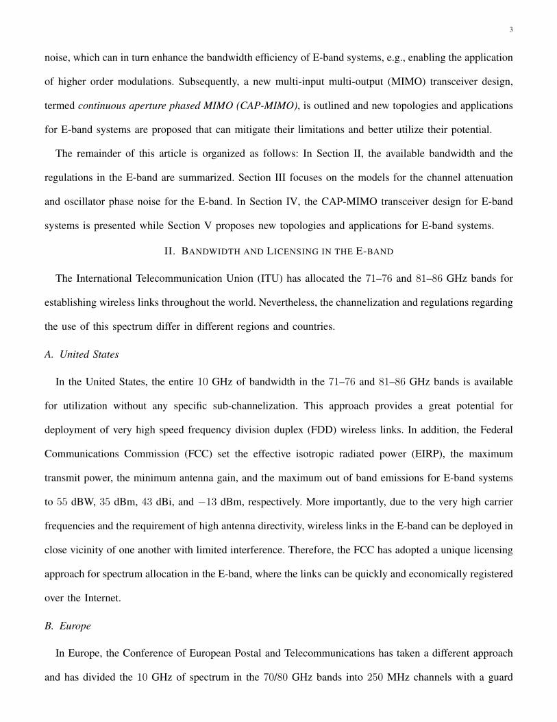
II. BANDWIDTH AND LICENSING IN THE E-BAND
The International Telecommunication Union (ITU) has allocated the 71–76 and 81–86 GHz bands for
establishing wireless links throughout the world. Nevertheless, the channelization and regulations regarding
the use of this spectrum differ in different regions and countries.
A. United States
In the United States, the entire 10 GHz of bandwidth in the 71–76 and 81–86 GHz bands is available
for utilization without any specific sub-channelization. This approach provides a great potential for
deployment of very high speed frequency division duplex (FDD) wireless links. In addition, the Federal
Communications Commission (FCC) set the effective isotropic radiated power (EIRP), the maximum
transmit power, the minimum antenna gain, and the maximum out of band emissions for E-band systems
to 55 dBW, 35 dBm, 43 dBi, and −13 dBm, respectively. More importantly, due to the very high carrier
frequencies and the requirement of high antenna directivity, wireless links in the E-band can be deployed in
close vicinity of one another with limited interference. Therefore, the FCC has adopted a unique licensing
approach for spectrum allocation in the E-band, where the links can be quickly and economically registered
over the Internet.
B. Europe
In Europe, the Conference of European Postal and Telecommunications has taken a different approach
and has divided the 10 GHz of spectrum in the 70/80 GHz bands into 250 MHz channels with a guard

4
band of 125 MHz at the top and bottom end of each band. Thus, each 5 GHz band consists of 19 channels
that can be used for both FDD and time division duplex operation. Moreover, the regulations in the E-band
in Europe are more stringent than the FCC rules. Specifically, in Europe the EIRP, the maximum transmit
power, the minimum antenna gain, and the maximum out of band emissions are set to 55 dBW, 30 dBm,
38 dBi, and −30 dBm, respectively, where the EIRP and the maximum transmit power are also functions
of the antenna gain and are expected to be lowered as the antenna gain increases.
C. Asia
The 70/80 GHz bands are under consideration for licensing in Japan, China, and most other Asian
countries and are not yet available for commercial use.
III. CHANNEL AND PHASE NOISE MODELS FOR THE E-BAND
Accurate channel and oscillator phase noise models for the E-band spectrum are essential for link budget
10−4
10−3
10−2
10−1
100
101
102
0
5
10
15
20
25
30
35
Pat
h A
ttenu
atio
n [d
B]
Percentage of time %
Actual attenuationAtt. from rain intensityAtt. Crane modelAtt. ITU−R model
Fig. 1. Path attenuation versus time with transmit power=18.6 dBm, receiver
threshold=−58 dBm, antenna gain=43 dBi, Tx/Rx separation=1 km ±50 m,
data rate=1.25 Gbps, differential BPSK (the measurements are also reported
in [9]).
planning and accurate tracking of phase noise
in E-band systems. Both of these improve-
ments are expected to enhance the bandwidth
efficiency of E-band systems in the near
future [7]. Thus, in this section, we examine
the accuracy of the existing models for both
phenomena in the E-band.
A. Channel and Propagation Characteristics
in E-band
To accurately predict the effect of envi-
ronmental conditions on the performance of
wireless communication systems, the ITU-R
and Crane models have been extensively applied for link-budget planning in the microwave band. In order
to determine the accuracy of these models in predicting rain intensity and the resulting signal attenuation

5
in the E-band, a long term measurement campaign was carried out in Gothenburg, Sweden, by Ericsson
Research, where the rain intensity and the signal attenuation of an E-band system was measured over
a period of nine months [9]. The results of this measurement campaign and a comparison with respect
to both the ITU-R and Crane models are plotted in Fig. 1. It can be observed that both the ITU-R and
Crane models can rather sufficiently predict the rain intensity in this region, since the signal attenuation
calculated based on the measured rain intensity is close to that of the ITU-R and Crane models. However,
the measurement results in Fig. 1 show that the measured signal attenuation in the E-band is considerably
higher than the attenuation predicted by both the ITU-R and Crane models. This demonstrates that both
models, which are well suited for the microwave band, are not capable of accurately predicting the channel
attenuation in the E-band. Thus, for E-band wireless point-to-point links to meet the expected 99.999%
availability requirements, the fade margin needs to be chosen larger than the values calculated using the
Crane and ITU-R models, e.g., 5–10 dB higher as shown in Fig. 1. This new finding indicates that to
avoid larger than necessary fade margins, more accurate channel attenuation models have to be developed
for the E-band. These more accurate channel and propagation models are also anticipated to enhance the
bandwidth efficiency of E-band systems.
Note that although the shortcomings of the ITU-R model in predicting the attenuation for E-band
systems has also been confirmed in [8], in this work, for the first time, we present a comparison with
respect to the Crane attenuation model, which is more extensively applied in North America.1
B. Phase Noise Models in E-band
One of the main challenges in E-band communication systems is to equip the transceivers with low
phase noise high-frequency oscillators. Nevertheless, recent studies have shown that such oscillators may
be designed using Gallium-Nitride technology, waveguide theory, and opto-electronic techniques [10], [11].
Generally, two methods are proposed to generate high-frequency oscillation [10], [11]. One is to design an
on-chip high-frequency oscillator and the other is to increase the frequency of a low-frequency oscillator by
1The work in [8] also provides a more accurate model compared to the ITU-R model for characterizing the channel and propagation
characteristics of wireless communication systems in the E-band.

6
means of frequency multipliers. Even though the former is expected to result in more accurate oscillators,
research has shown that the design of accurate and affordable oscillators for commercial applications via
this approach is a challenging task. On the other hand, the latter approach increases a low-frequency
oscillator’s phase noise variance by the so-called multiplication factor [10]. As a result, oscillator phase
noise is one of the main limiting factors in the application of higher order modulations in E-band systems
[4].
Although the effect of oscillator phase noise in narrowband systems has been extensively studied,
there is a lack of understanding of this impairment for the wideband systems deployed in the E-band.
According to traditional phase noise models, the phase noise variance or rate is linearly proportional to
the sampling time applied at the receiver [5]. Therefore, it is expected that systems employing larger
bandwidths and smaller sampling times will experience a smaller phase noise variance. However, by
increasing the signal bandwidth, other system parameters such as the bandwidth of the receiver front-end
filter must also be increased. Consequently, this leads to an increase in phase perturbation introduced to
the entire communication system.
103
104
105
106
107
−200
−180
−160
−140
−120
−100
−80
−60
−40
Offset Frequency [Hz]
L(f)
[dB
c/H
z]
Measured phase noise PSDWiener or traditional phase noise PSD
Phase Noise Floor
Fig. 2. The power spectral density of a free-running
oscillator operating at 9.9 GHz.
−170 −160 −150 −140 −130 −120 −110−45
−40
−35
−30
−25
−20
−15
−10
Noise Floor Level [dB]
Err
or V
ecto
r M
agni
tude
[dB
]
1/Ts=200M sym/s
1/Ts=1G sym/s
Fig. 3. EVM of residual phase noise error for two systems with
different symbol rates vs. oscillator phase noise floor power.
To illustrate this effect in wideband systems, Fig. 2 depicts the measured power spectral density (PSD)
of oscillator phase noise for a monolithic microwave integrated circuit oscillator operating at 9.9 GHz.

7
Fig. 2 compares measurement results with the traditional Wiener phase noise model, which is extensively
applied for the microwave band. Note that unlike the traditional phase noise models, the phase noise
PSD of an oscillator does not continue to decrease with increasing offset frequency. In fact, as shown in
Fig. 2, in practice, the phase noise PSD exhibits a floor region beyond a certain offset frequency.2 Thus,
as the bandwidth of a communication system increases, the floor region in the PSD of an oscillator is
expected to play an important role in the overall system’s performance. To verify this finding, in Fig. 3,
the performances of two communication systems with different bandwidths are compared in terms of the
error vector magnitude (EVM) (also known as receive constellation error) for different phase noise floor
levels (signal-to-noise ratio (SNR)= 30 dB and 16-QAM). Fig. 3 shows that below a certain noise floor
level, the cumulative phase noise is dominant and a system with higher symbol rate experiences a lower
EVM. However, as the phase noise floor increases, the performance of a communication system employing
a larger bandwidth degrades more dramatically. It is also important to consider that due to the use of
frequency multipliers, it is expected that most oscillators used in E-band systems have higher phase noise
floor levels. For example, if the above 9.9 GHz oscillator is used in an E-band system operating at 70
GHz, a frequency multiplier with a multiplication factor of 7 needs to be applied, which will increase the
noise floor by 20 log 7 = 16.9 dBc. Therefore, from the results in Figs. 2 and 3, it can be concluded that
the phase noise models that are used for narrowband systems, e.g., the Wiener model, cannot be applied to
accurately predict the properties of this impairment in wideband systems. Thus, more accurate phase noise
models for wideband communication systems have to be developed to estimate and compensate the effect
of phase noise more effectively, which in turn enables the use of more bandwidth-efficient modulation
schemes.
IV. MIMO TRANSCEIVER DESIGN FOR E-BAND SYSTEMS
The development of MIMO technology has been largely based on the assumption of rich multipath
which combined with the deployment of multiple antennas results in multiple independent spatial channels
between two terminals. Under these circumstances, it has been theoretically shown that the MIMO system
2This effect is not exclusive to this oscillator and is also reported in [5] and references therein.

8
capacity scales linearly with the minimum of the number of transmit and receive antennas. However, E-
band systems are expected to operate under strong LOS conditions, thereby creating several research
challenges and opportunities for the design of efficient E-band MIMO transceivers [3], [12], [13]. More
importantly, the antenna properties in the E-band are attractive for three important reasons:
1) they result in high antenna gains for a given antenna size,
2) they enable highly directional communication with narrow beams, thus, reducing interference, and
3) they support the deployment of large-dimensional MIMO systems with relatively compact antenna
arrays.
Two benchmark E-band systems dominate the current state-of-the-art. In the first configuration, termed
a DISH system, conventional continuous aperture “dish” antennas are used in highly directional LOS
point-to-point links. Such systems are currently used for wireless backhaul links, e.g., in the commercial
systems offered by Siklu, E-band Communications, or Bridgewage. In the second configuration, termed
conventional MIMO, the antenna elements are placed sufficiently far apart so that the spatial LOS responses
become independent. The required antenna spacing can be worked out via simple geometrical arguments,
and leads to the so-called Rayleigh spacing. For a given transmitter-receiver distance, the Rayleigh antenna
spacing is inversely proportional to the carrier frequency. Thus, compared to microwave systems, LOS
MIMO technology is more suitable for E-band systems, since the antenna spacing is smaller and the
transceivers can be housed within a relatively compact module. However, while such systems can exploit
multiplexing gains, they suffer from poor power efficiency and increased interference [12]. In principle,
the above limitations of conventional MIMO systems can be eliminated by using half-wavelength spaced
large antenna arrays. Although such systems can optimally exploit the spatial dimension, they suffer from
a prohibitively high transceiver complexity due to the requirement of a large number of array elements.
For example, a 6′′ planar array operating at 80 GHz requires about 6400 antenna elements, while each
antenna element requires a dedicated transceiver module [12].
Recall that propagation in the E-band is expected to have sparse multipath components and is predom-
inantly LOS. Thus, the the spatial multiplexing gain of a MIMO E-band system can, in practice, be much

9
Fig. 4. Radio unit for an E-band CAP-MIMO system.
smaller than the minimum of the number of transmit and receive antennas employed. In other words,
compared to a system in the microwave band, the spatial communication subspace for a MIMO E-band
system can be expressed with a smaller number of orthogonal basis functions [3], [12]. Accordingly, to
fully exploit the potential of MIMO technology and to reduce the transceiver complexity, the number of
beams transmitted or received by a MIMO E-band system needs to be equal to the dimensionality of the
E-band channel subspace. This characteristic of E-band channels has motivated the development of the
CAP-MIMO transceiver.
CAP-MIMO combines the multiplexing gain of MIMO systems, the antenna gain of DISH systems,
and the beamforming capability of phased arrays to optimally exploit the smaller spatial dimensionality
at E-band frequencies [12]. CAP-MIMO uses a high-resolution discrete lens array to perform analog
beamforming in the passband, see Fig. 4. Essentially, in this setup, a relatively small number of active
beams are radiated by the corresponding feed antennas on the focal surface of the lens array. The number
of transmitted beams is directly proportional to the dimensionality of the communication channel. This

10
approach ensures that the CAP-MIMO transceiver is equipped with the smallest number of A/D, D/A, and
radio frequency units, while fully taking advantage of the potential of MIMO technology. Fig. 4 depicts
the radio unit for a CAP-MIMO system. In this setup, it is assumed that 5 spatially independent channels
can be established between transmitter and receiver. Consequently, the CAP-MIMO system only requires
5 transceiver blocks. The beam selector block in Fig. 4 ensures that appropriate beams are selected for
signal transmission and reception, which is analogous to an antenna selection block in a conventional
MIMO system.
Fig. 5 compares the bandwidth efficiency of CAP-MIMO with a conventional MIMO system with
widely spaced antennas, and a DISH system for a point-to-point LOS link at 80 GHz. The link length
is about 200 m. The antenna size for the DISH and CAP-MIMO systems is 0.6 m × 0.6 m with an
antenna gain of 55 dBi. The conventional MIMO system has 4 widely spaced antennas at each end,
Fig. 5. Bandwidth efficiency comparison of CAP-MIMO, conventional MIMO, and
DISH systems.
where each antenna has a gain of 30
dBi. The CAP-MIMO system is as-
sumed to take advantage of 4 transmit
and receive beams. One important ob-
servation is that the DISH system is
optimum at low SNRs, whereas conven-
tional MIMO outperforms DISH at high
SNRs. CAP-MIMO yields the best per-
formance across the entire SNR range,
thereby representing a robust scheme for
realizing the advantages offered in the
E-band. CAP-MIMO can achieve a spectral efficiency of 30 bits/s/Hz, at a normalized SNR of −8 dB
with an SNR gain of about 25 dB, over the other two systems. This results in a data rate of 30–300 Gbps
for a bandwidth of 1–10 GHz. For the given antenna size, a system operating in the 3 GHz band, i.e.,
the microwave band, at best achieves a spectral efficiency of 10 bits/s/Hz at a much higher SNR of 40

11
dB. This corresponds to a maximum data rate of 5 Gbps when considering a generous bandwidth of 500
MHz. Finally, CAP-MIMO also offers a promising route to electronic multi-beamforming and steering
which can be exploited for a number of attractive operational functions, such as user tracking in mobile
environments, multi-beam steering in point-to-multipoint links, and formation of high capacity cooperative
MIMO links (see Section V-A).
It is important to note that although the use of multi-antenna arrays in E-band systems has been studied
[6], they are only used for power combining and not MIMO spatial multiplexing gain. As such, the
CAP-MIMO concept presented here promises to provide spectral efficiencies that are significantly higher
than the approach in [6], e.g., 30 bits/s/Hz for CAP-MIMO compared to 4.8 bits/s/Hz for the approach
in [6]. Moreover, this article uniquely provides a comprehensive comparison between the throughput of
traditional MIMO and DISH systems at different SNRs.
V. E-BAND POINT-TO-POINT SYSTEMS IN NEXT GENERATION CELLULAR NETWORKS
With respect to point-to-point wireless links, e.g., backhaul links, the most important issues for cellular
providers are range, very high link availability, and operating costs. To facilitate the application of E-band
systems in next generation cellular networks, we propose to employ full-duplex relaying to extend the range
of E-band links. Moreover, the challenges and potentials for applying E-band systems for backhauling in
heterogeneous networks (HetNets) are presented.
A. Full-Duplex Multi-Hop Cooperative Relay Networks
The research in the field of cooperative relay networks has shown that such systems can significantly
enhance the coverage area and reliability of point-to-point wireless links [14]. Regenerative and non-
regenerative relaying, i.e., decode-and-forward (DF) and amplify-and-forward (AF) relaying, respectively,
have gained significant traction due to their performance and simplicity. However, most of the research
in this area has been focused on half-duplex cooperative relaying, where one node transmits while the
remaining nodes stay silent. This approach reduces the throughput of the network for every additional
hop. Moreover, although full-duplex relaying circumvents the shortcomings of half-duplex relaying, its
implementation in the microwave band has been a challenging task. One approach is for the relays to
12
Decode & Forward
or
Amplify & Forward
Relay Node
Decode & Forward
or
Amplify & Forward
Relay Node
Decode & Forward
or
Amplify & Forward
Relay Node
Destination
NodeSource
Node
Data Stream 1
Data Stream 3
Data Stream 2 Data Stream 2
Data Stream 3
Data Stream 1
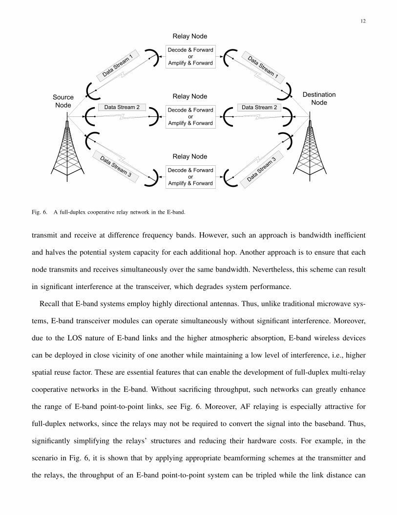
Fig. 6. A full-duplex cooperative relay network in the E-band.
transmit and receive at difference frequency bands. However, such an approach is bandwidth inefficient
and halves the potential system capacity for each additional hop. Another approach is to ensure that each
node transmits and receives simultaneously over the same bandwidth. Nevertheless, this scheme can result
in significant interference at the transceiver, which degrades system performance.
Recall that E-band systems employ highly directional antennas. Thus, unlike traditional microwave sys-
tems, E-band transceiver modules can operate simultaneously without significant interference. Moreover,
due to the LOS nature of E-band links and the higher atmospheric absorption, E-band wireless devices
can be deployed in close vicinity of one another while maintaining a low level of interference, i.e., higher
spatial reuse factor. These are essential features that can enable the development of full-duplex multi-relay
cooperative networks in the E-band. Without sacrificing throughput, such networks can greatly enhance
the range of E-band point-to-point links, see Fig. 6. Moreover, AF relaying is especially attractive for
full-duplex networks, since the relays may not be required to convert the signal into the baseband. Thus,
significantly simplifying the relays’ structures and reducing their hardware costs. For example, in the
scenario in Fig. 6, it is shown that by applying appropriate beamforming schemes at the transmitter and
the relays, the throughput of an E-band point-to-point system can be tripled while the link distance can

13
be doubled.
B. E-band Systems in Heterogeneous Networks
To meet the surge in the number of users and each user’s throughput requirements, cellular providers
have resorted to increasing the number and density of macrocell base stations (BSs). However, as these
throughput demands continue to grow, large BSs cannot effectively meet users’ needs in different settings,
e.g., in indoor environments and at the cell edges [15]. Moreover, macrocell BSs are expensive to deploy
and maintain. Thus, next generation cellular networks are expected to adopt the HetNet paradigm, where
smaller and more specialized cells are deployed by the operators, e.g., picocells in urban areas and
femtocells in indoor environments [15]. Furthermore, to mitigate interference, achieve smooth hand-offs
from tier to tier, and enable cooperation amongst different tiers, fast backhaul links are of paramount
importance.
Since picocells and femtocells have smaller coverage areas, they can be deployed more densely through-
out a cellular network. Moreover, E-band systems are capable of establishing multi-Gbps wireless links
over short distances. Thus, they are well suited for establishing backhaul links amongst different tiers
within a cell. Due to the high atmospheric absorption and the use of highly directional antennas, they can
do so without causing significant interference.
There are, however, some challenges that need to be addressed. Most femtocells are expected to be
deployed in indoor environments. Since E-band radio signals do not penetrate obstacles and buildings
very well, E-band backhaul links may require the application of strategically positioned relays throughout
the network to establish reliable connectivity between femtocell and macrocell BSs. Another challenging
issue, is the high development cost of E-band transceivers. This is especially important for the development
of next generation HetNets, since femtocell and picocell BSs are expected to be relatively inexpensive
to manufacture. Nevertheless, recent research in the field of semiconductor design and fabrication, e.g.,
Silicon-Germanium and Gallium-Nitride, is expected to reduce the manufacturing costs of E-band systems
and facilitate their adoption [4].

14
VI. SUMMARY
In this article, to gain a better understanding of the effects of channel attenuation and phase noise on
E-band systems, measurement results for both phenomena were compared against existing models. It was
concluded that the ITU-R and Cane models may not be able to accurately determine the fade margin for
E-band systems, e.g., if these models are used to obtain the required fade margin for an E-band link with
99.999% availability, the result may be 5–10 dB below the actual required value. These measurements
also indicated that the floor in the PSD of oscillator phase noise may more significantly influence the
performance of wideband systems operating in the E-band compared to the narrowband systems in the
microwave band. Further research in this field is anticipated to result in E-band transceivers that can
employ higher order modulations and improved bandwidth efficiency. Next, we showed that the CAP-
MIMO transceiver design can enable E-band systems to achieve bandwidth efficiencies of up to 30 b/s/Hz
(data rates of up to 300 Gbps). Finally, it was proposed that due to application of highly directional
antennas and the LOS nature of E-band links, full-duplex relaying can be used to extend the range of
E-band systems and to facilitate their application in next generation heterogeneous cellular networks.
REFERENCES
[1] X. Huang, Y. J. Guo, A. Zhang, and V. Dyadyuk, “A multi-gigabit microwave backhaul,” IEEE Commun. Mag., vol. 50, no. 3, pp.
122–129, Mar. 2012.
[2] J. Wells, “Faster than fiber: The future of multi-G/s wireless,” IEEE Micr. Mag., vol. 10, no. 3, pp. 104–112, Mar. 2009.
[3] Z. Pi and F. Khan, “An introduction to millimeter-wave mobile broadband systems,” IEEE Commun. Mag., vol. 49, no. 6, pp. 101–107,
Jun. 2011.
[4] J. Wells, Multi-Gigabit Microwave and Millimeter-Wave Wireless Communications. Artech House, 2010.
[5] A. Chorti and M. Brookes, “A spectral model for RF oscillators with power law phase noise,” IEEE Trans. Circuits Syst., vol. 53,
no. 9, pp. 1989–1999, Sep. 2006.
[6] V. Dyadyuk, J. D. Bunton, and Y. J. Guo, “Study on high rate long range wireless communications in the 71-76 and 81-86 Ghz bands,”
in Proc. European Microwave Conf. (EuMC), Oct. 2009, pp. 1315–1318.
[7] Z. He, W. Wu, J. Chen, Y. Li, D. Stackenas, and H. Zirath, “An FPGA-based 5 Gbit/s D-QPSK modem for E-band point-to-point
radios,” in Proc. European Microwave Conf. (EuMC), Oct. 2011.
[8] L. Csurgai-Horvath, I. Frigyes, and J. Bito, “Propagation and availability on E-band terrestrial radio,” in Proc. European Conf. Ant.
Propag (EuCAP), Mar. 2012, pp. 73–75.
15
[9] J. Hansryd, L. Yinggang, J. Chen, and P. Ligander, “Long term path attenuation measurement of the 71–76 GHz band in a 70/80 GHz
microwave link,” in Proc. European Conf. Ant. Propag. (EuCAP), Apr. 2010.
[10] P. Russer, “Si and SiGe millimeter-wave integrated circuits,” IEEE Trans. Microw. Theory Tech., vol. 46, no. 5, pp. 590–603, May
1998.
[11] E. Ruscito, H. Chuang, R. Amaya, L. Roy, and B. Syrett, “A low cost oscillator for high data rate E-band transceivers,” in Proc. Fly
Wireless Work. (FBW), Jun. 2011.
[12] A. M. Sayeed and N. Behdad, “Continuous aperture phased MIMO: Basic theory and applications,” in Proc. Allerton Conf. Control,
Comput., Sep. 2010.
[13] F. Bøhagen, P. Orten, and G. E. Øien, “Design of capacity-optimal high-rank line-of-sight MIMO channels,” IEEE Trans. Wireless
Commun., vol. 4, no. 6, pp. 790–804, Apr. 2007.
[14] Z. Sheng, K. K. Leung, and Z. Ding, “Cooperative wireless networks: From radio to network protocol designs,” IEEE Commun. Mag.,
vol. 49, no. 5, pp. 64–69, May 2011.
[15] A. Ghosh et al., “Heterogeneous cellular networks: From theory to practice,” IEEE Commun. Mag., vol. 50, no. 6, pp. 54–64, Jun.
2012.