improvements of driver fatigue detection system based on eye tracking and dynamic template
TRANSCRIPT
Improvements of Driver Fatigue Detection System Based on Eye Tracking and Dynamic Template Matching
WEN-BING HORNG1, CHIH-YUAN CHEN2, JIAN-WEN PENG3, CHEN-HSIANG CHEN4
1, 2, 4Department of Computer Science and Information Engineering Tamkang University
151 Ying-Chuan Road, Tamsui, Taipei, Taiwan 25137 3Department of Commerce Technology and Management
Chihlee Institute of Technology 313, Section 1, Wunhua Road, Banciao, Taipei, Taiwan 22050
REPUBLIC OF CHINA [email protected], [email protected],
[email protected], [email protected] Abstract: - Driver fatigue detection plays an important role in intelligent transportation systems for driving safety. Therefore, it becomes an essential research issue these years. Recently, Horng and Chen proposed a real-time driver fatigue detection system based on eye tracking and dynamic template matching. In their work, the driver fatigue detection system consists of four parts: face detection, eye detection, eye tracking, and fatigue detection. However, their work suffers from an exhaustive search in eye tracking with the conventional mean absolute difference (MAD) matching function. To remedy the low accuracy in matching and inefficiency in search, in this paper, we first propose two new matching functions, the edge map overlapping (EMO) and the edge pixel count (EPC), to enhance matching accuracy. In addition, we utilize fast search algorithms, such as the 2D-log search and the three-step search algorithms, to expedite search. The experimental results show that the 2D-log search with the EPC matching function has the best performance on eye tracking; it only requires 22.29 search points on average to achieve 99.92% correct rate of eye tracking, as comparing to the original work which requires 441 search points with only 96.01% correct rate. By theoretical analysis, the total amount of computations for eye tracking in the 2D-log search with EPC only takes up to about 10% of the original work. These improvements make the driver fatigue detection system more suitable for implementations in embedded systems. Key-Words: - Intelligent transportation system; Driving safety; Driver fatigue detection; Eye tracking;
Template matching. 1 Introduction Driver fatigue has been one of the major causes of traffic accidents all over the world. As reported in [19], in UK it was estimated that more than 20% of traffic accidents have resulted from driver fatigue, while in the US there are around 50% of fatigue-related fatal accidents. Therefore, many countries have invested lots of funds in building intelligent transportation systems to provide more road safety. In addition, researchers have begun to pay more attentions to the driving safety problem to decrease road crashes.
To improve driving safety, the related research in the literature can be roughly categorized into three approaches. The first one is to study the drivers’ mental states relating to driving safety [16][17] or the cause of driver fatigue resulted from sleep
deprivation [25]. The second approach is to devise auxiliary equipments to improve driving safety, such as by designing special car seats [2], by mon-itoring grip force change on the steering wheel [1], or by analyzing EEG (Electroencephalogram) re-cordings from sensors attached to the human body [13][20][24]. The third one is based on image processing techniques [6] to detect drivers’ fatigue to enhance driving safety. Some of these researchers utilized expensive infrared or near-infrared CCD cameras for easily locating eye positions [3][7][8] [11][14][27], while others employed ordinary CCD cameras or cheaper webcams for practical usage [4] [5][10][18][21][22][23][26]. However, most of the above image-based driver fatigue detection systems suffer from the illumination change problem. In addition, they might not be suitable for real-time
WSEAS TRANSACTIONS on INFORMATION SCIENCE and APPLICATIONS
Wen-Bing Horng, Chih-Yuan Chen, Jian-Wen Peng, Chen-Hsiang Chen
E-ISSN: 2224-3402 14 Issue 1, Volume 9, January 2012

applications due to their complicated computations in nature.
Recently, Horng and Chen [10] proposed a vision-based real-time driver fatigue detection system based on webcams to cope with the above deficiencies. The system can be divided into four parts: face detection, eye detection, eye tracking, and fatigue detection. It was tested that the average correct rate of eye tracking could reach 96.01% and the overall correct rate of driver fatigue detection of the system could achieve 100%. However, during the eye tracking phase of the system, the exhaustive search with the conventional mean absolute differ-ence (MAD) matching function is used.
In this paper, we improve the Horng-Chen’s eye tracking method by increasing both matching accuracy and search efficiency. First, we propose two new matching functions, the edge map over-lapping (EMO) and the edge pixel count (EPC), specifically designed for eye tracking to increase matching accuracy. In addition, we also apply fast search algorithms, such as 2D-log search [12] and three-step search [15] used in video coding [9], to reduce search computation. The experimental results show that in the original exhaustive search for eye tracking, it requires 441 search points if the search range is 10 pixels in each of four directions; however, in the 2D-log and three-step searches, they require only about 24 and 33 search points on average, respectively. As to the correct rate for eye tracking, the exhaustive, 2D-log, and three-step searches can achieve 99.80%, 99.79%, and 99.86%, respectively, if the EMO matching function is used, while they are 99.85%, 99.92%, and 99.79%, respectively, if EPC is used. These results are much better than the original exhaustive search based on the MAD matching function whose correct rate is 96.01% only. The experimental results suggest that the 2D-log search with the simple EPC matching function can greatly improve the performance of the original eye tracking method in terms of search efficiency and matching accuracy. It can achieve 99.92% correct rate of eye tracking while requiring only up to about 10% of computations of the original work.
The rest of the paper is organized as follows. In Section 2, we briefly review Horng-Chen’s driver fatigue detection system. In Section 3, we propose two new matching functions to enhance matching accuracy and apply fast search algorithms to accelerate search efficiency for eye tracking. The experimental results are analyzed in Section 4. Finally, we conclude the paper in the last section.
2 Brief Review of Horng-Chen’s Driver Fatigue Detection System
In this section, we briefly review Horng-Chen’s driver fatigue detection system [10]. The system consists of four components: face detection, eye detection, eye tracking, and fatigue detection. Fig. 1 shows the flow chart of the driver fatigue detection system.
Fig. 1 Flow chart of Horng-Chen’s driver fatigue detection algorithm
At first, a webcam or an ordinary color CCD camera is mounted on the dash board of a car to capture the images of the driver for fatigue detection. The first frame is used for initial face detection and eye location. If any one of these detection proce-dures fails, then go to the next frame and restart the above detection processes. Otherwise, the current eye subimages are used as the dynamic templates for eye tracking on subsequent frames, and then the fatigue detection process is performed. If the eye
load next frame
face detection
locate eye region
eye detection
save eye templates
load next frame
eye tracking
driver fatigue detection
more frames?
failure
failure
failure
success
success
success
yes
no
WSEAS TRANSACTIONS on INFORMATION SCIENCE and APPLICATIONS
Wen-Bing Horng, Chih-Yuan Chen, Jian-Wen Peng, Chen-Hsiang Chen
E-ISSN: 2224-3402 15 Issue 1, Volume 9, January 2012

tracking fails, the face detection and eye location processes restart on the current frame. These proce-dures continue until there are no more frames. 2.1 Face Detection The RGB color space used to represent color frames is first converted into the HSI color space for face detection to exclude the brightness factor from affecting skin color detection to cope with the illumination change problem. A suitable range of hue values as well as horizontal and vertical projections can correctly detect the face region. The upper 2/5 of the detected face region, called the eye region, is used for eye location. Fig. 2(a) is a driver image. After performing face detection, the eye region enclosed in a bounding box is shown in Fig. 2(b).
(a) Original image (b) Eye region
Fig. 2 Result of face detection 2.2 Eye Detection The original color information of the detected eye region is first converted into gray scale. Then, the Sobel edge operator [6] is used for edge detection in the gray-level eye region, gr, as follows. In order to reduce computation, an approximate edge magni-tude, mag(x, y), of a pixel (x, y) in gr is computed as follows:
mag(x, y) = |S1(x, y)| + |S2(x, y)| (1) where S1(x, y) and S2(x, y) are the Sobel horizontal and vertical gradient values of pixel (x, y), respec-tively, and |z| represents the absolute value of z.
The edge map, er, of the gray-level eye region gr is defined by
≥
otherwise , ) ,( if ,
= ) ,(white
Tyxmagblackyxer (2)
where black and white stand for the black and white pixel values, respectively, and T for some threshold.
Next, perform horizontal projection on the edge map er to find the vertical position of the eyes. Then,
the left and right eye positions can be located by finding the largest connected components in er from the center. Finally, the eye subimages in the gray-level eye region gr are located, which are used as the dynamic eye templates for eye tracking. Figs. 3(a) and 3(b) show the gray-level eye region image and its corresponding edge map. After performing eye detection, two eye templates enclosed in bounding boxes are also shown in Fig. 3.
(a) Eye region (b) Edge map
Fig. 3 Result of eye detection 2.3 Eye Tracking Consider an eye template gt of width w and height h, located at the position (a, b) in the original frame. The search area of a new frame for eye tracking is the eye template position by expanding a reasonable number of pixels in each of four directions: left, right, up, and down, as depicted in Fig. 4. Let dx_max and dy_max be the maximum displacements of the x-axis and y-axis, respectively. Thus, the size of the search area is (w + 2dx_max) × (h + 2dy_max), and the number of search points for the exhaustive search is equal to (2dx_max + 1) × (2dy_max + 1). This search area in the new color frame is first converted into a gray-level one, gs, for eye tracking.
Fig. 4 Search area of an eye template for tracking
The following mean absolute difference (MAD) matching function is used for eye template matching:
( ) ( )∑∑=
−
=
++−1-
0
1
0,, = ) ,(
w
x
h
yst qypxgyxgqpM (3)
h + 2dy_max
w + 2dx_max
eye template
w
h
dx max
dx max
dy max
dy max
WSEAS TRANSACTIONS on INFORMATION SCIENCE and APPLICATIONS
Wen-Bing Horng, Chih-Yuan Chen, Jian-Wen Peng, Chen-Hsiang Chen
E-ISSN: 2224-3402 16 Issue 1, Volume 9, January 2012
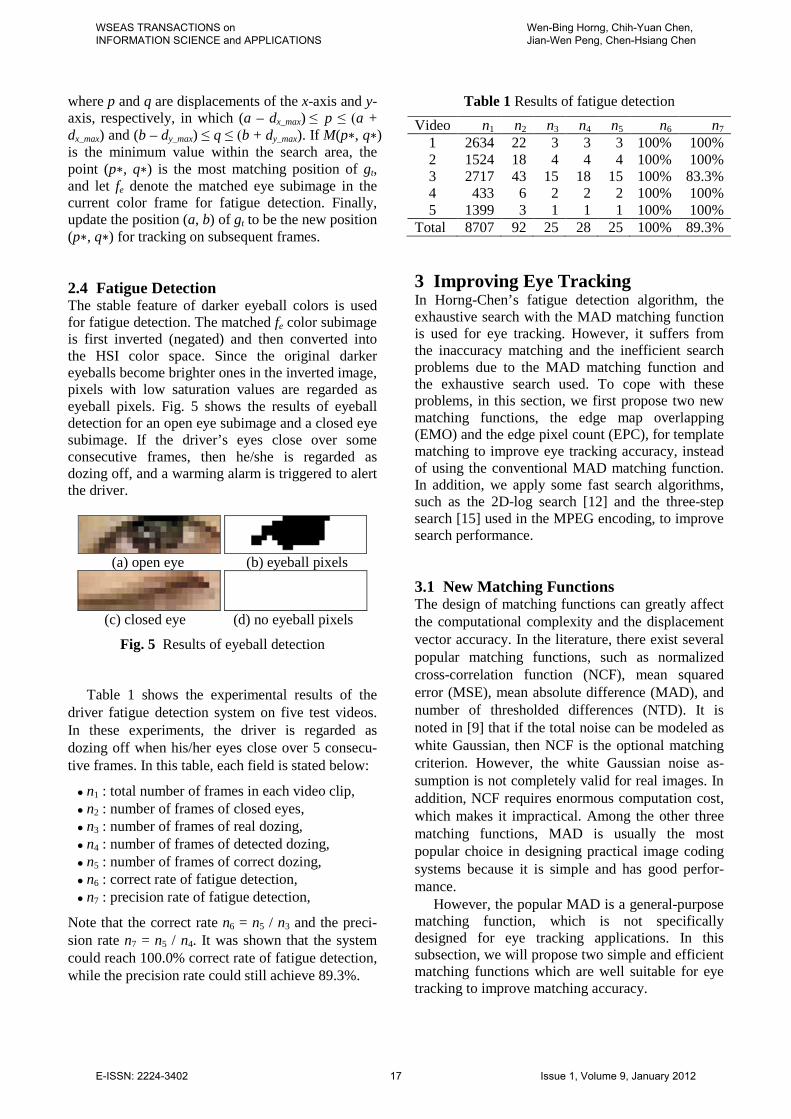
where p and q are displacements of the x-axis and y-axis, respectively, in which (a – dx_max) ≤ p ≤ (a + dx_max) and (b – dy_max) ≤ q ≤ (b + dy_max). If M(p∗, q∗) is the minimum value within the search area, the point (p∗, q∗) is the most matching position of gt, and let fe denote the matched eye subimage in the current color frame for fatigue detection. Finally, update the position (a, b) of gt to be the new position (p∗, q∗) for tracking on subsequent frames. 2.4 Fatigue Detection The stable feature of darker eyeball colors is used for fatigue detection. The matched fe color subimage is first inverted (negated) and then converted into the HSI color space. Since the original darker eyeballs become brighter ones in the inverted image, pixels with low saturation values are regarded as eyeball pixels. Fig. 5 shows the results of eyeball detection for an open eye subimage and a closed eye subimage. If the driver’s eyes close over some consecutive frames, then he/she is regarded as dozing off, and a warming alarm is triggered to alert the driver.
(a) open eye (b) eyeball pixels
(c) closed eye (d) no eyeball pixels
Fig. 5 Results of eyeball detection
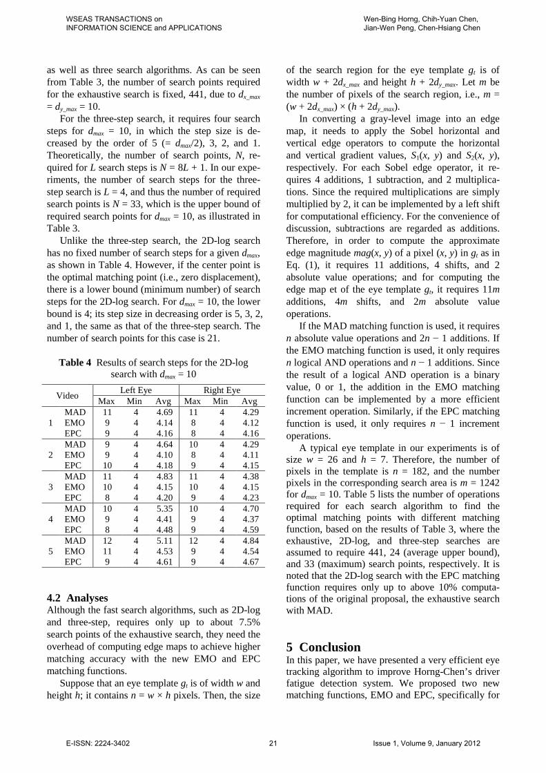
Table 1 shows the experimental results of the driver fatigue detection system on five test videos. In these experiments, the driver is regarded as dozing off when his/her eyes close over 5 consecu-tive frames. In this table, each field is stated below:
n1 : total number of frames in each video clip, n2 : number of frames of closed eyes, n3 : number of frames of real dozing, n4 : number of frames of detected dozing, n5 : number of frames of correct dozing, n6 : correct rate of fatigue detection, n7 : precision rate of fatigue detection,
Note that the correct rate n6 = n5 / n3 and the preci-sion rate n7 = n5 / n4. It was shown that the system could reach 100.0% correct rate of fatigue detection, while the precision rate could still achieve 89.3%.
Table 1 Results of fatigue detection Video n1 n2 n3 n4 n5 n6 n7
1 2634 22 3 3 3 100% 100% 2 1524 18 4 4 4 100% 100% 3 2717 43 15 18 15 100% 83.3% 4 433 6 2 2 2 100% 100% 5 1399 3 1 1 1 100% 100%
Total 8707 92 25 28 25 100% 89.3% 3 Improving Eye Tracking In Horng-Chen’s fatigue detection algorithm, the exhaustive search with the MAD matching function is used for eye tracking. However, it suffers from the inaccuracy matching and the inefficient search problems due to the MAD matching function and the exhaustive search used. To cope with these problems, in this section, we first propose two new matching functions, the edge map overlapping (EMO) and the edge pixel count (EPC), for template matching to improve eye tracking accuracy, instead of using the conventional MAD matching function. In addition, we apply some fast search algorithms, such as the 2D-log search [12] and the three-step search [15] used in the MPEG encoding, to improve search performance. 3.1 New Matching Functions The design of matching functions can greatly affect the computational complexity and the displacement vector accuracy. In the literature, there exist several popular matching functions, such as normalized cross-correlation function (NCF), mean squared error (MSE), mean absolute difference (MAD), and number of thresholded differences (NTD). It is noted in [9] that if the total noise can be modeled as white Gaussian, then NCF is the optional matching criterion. However, the white Gaussian noise as-sumption is not completely valid for real images. In addition, NCF requires enormous computation cost, which makes it impractical. Among the other three matching functions, MAD is usually the most popular choice in designing practical image coding systems because it is simple and has good perfor-mance.
However, the popular MAD is a general-purpose matching function, which is not specifically designed for eye tracking applications. In this subsection, we will propose two simple and efficient matching functions which are well suitable for eye tracking to improve matching accuracy.
WSEAS TRANSACTIONS on INFORMATION SCIENCE and APPLICATIONS
Wen-Bing Horng, Chih-Yuan Chen, Jian-Wen Peng, Chen-Hsiang Chen
E-ISSN: 2224-3402 17 Issue 1, Volume 9, January 2012

3.1.1 Edge Map Overlapping Matching Function In a human face, there are eyelashes, eyelids, irises, and pupils around the eyes. Therefore, the eyes have prominent edges around them, as already shown in Fig. 3(b). This complicated edge feature of the eye has already been used for eye location, as discussed in Section 2.2. However, it can also be further used for eye tracking. In order to use edge feature for designing new matching functions, the search area and the eye template must first be converted into their corresponding edge maps based on Eq. (2). For this purpose, the edge pixel value black and non-edge pixel value white in Eq. (2) are set to 1 and 0, respectively, for convenience and efficiency of com-putation.
As defined in Section 2.3, let gt be an eye template of width w and height h, located at the position (a, b). The search area of a new frame for eye tracking is the eye template position by ex-panding dx_max pixels in both directions along with the x-axis and by dy_max pixels in both directions along with the y-axis (Fig. 4). Suppose that gs is the gray-level image of this search area in the new color frame for eye tracking. Let es and et be the edge maps of the search area gs and the eye template gt, respectively. Then, the edge map overlapping (EMO) matching function is defined as follows:
( ) ( ) ( )∑∑−
=
−
=
++⋅=1
0
1
0,,,
w
x
h
yst qypxeyxeqpE (4)
where the operator “·” represents the logical-AND operation, and p and q are displacements of the x-axis and y-axis, respectively, in which (a – dx_max) ≤ p ≤ (a + dx_max) and (b – dy_max) ≤ q ≤ (b + dy_max). The more the overlapped edge pixels there are, the higher the matched value is. 3.1.2 Edge Pixel Count Matching Function We further observe that since the eyes have promi-nent edges around them within the search area, the number of edge pixels could be another stable feature for eye tracking. In this case, the eye tem-plate is regarded as a sliding window moving within the search area. We only need to count the number of edge pixels in the moving window. Thus, the edge pixel count (EPC) matching function is defined as follows:
( ) ( )∑∑−
=
−
=
++=1
0
1
0,,
w
x
h
ys qypxeqpC (5)
where p and q are displacements of the x-axis and y-axis, respectively, in which (a − dx_max) ≤ p ≤ (a + dx_max) and (b – dy_max) ≤ q ≤ (b + dy_max). The more the number of edge pixels is counted, the more likely the eye position will be. 3.2 Fast Search Algorithms As shown in Section 2.3, the exhaustive search needs to examine every search point within the search area, trying to find the best possible match. However, it requires a large amount of computations. In order to reduce the computational cost, several fast algorithms have been proposed at the price of slightly impaired performance. In general, a fast search algorithm starts with a rough search of a set of scattered search points. The distance between two nearby search points is called step size. At the end of each search step, the most promising search point becomes the new center point and another search step continues with probably a smaller step size. The above procedure is repeated until step size is equal to one, and the (local) optimum position is reached.
Note that as pointed out in [9], [12], if the matching function is monotonic along any direction away from the optimal point, it is guaranteed that a well-designed fast search algorithm can converge to the global optimal point. However, the real image signal is not a simple Markov process, and it con-tains coding and measurement noises. Therefore, the monotonic matching function assumption is often invalid, and consequently fast search algorithms are often suboptimal. 3.2.1 2D-Log Search The 2D-log search scheme was proposed by Jain and Jain [12]. It starts from the center point (zero displacement) of the search area to find the best match of the eye template based on some matching function. Fig. 6 illustrates an example of the 2D-log search procedure, where circles represent the search points, and the number enclosed in each circle stands for the search step. In each search step, five search points in the search area with a diamond-shape are searched; they are the center point (the best matching point in the last step) and the four corner points of the diamond-shape with a fixed step size, r, as shown in Fig. 6. Let dmax be the maximum search range in both x-axis and y-axis, i.e., dmax = max(dx_max, dy_max). The initial value of r is set to max(2, 2m−1), where m = max2log d and z denotes the largest integer less than or equal to z.
WSEAS TRANSACTIONS on INFORMATION SCIENCE and APPLICATIONS
Wen-Bing Horng, Chih-Yuan Chen, Jian-Wen Peng, Chen-Hsiang Chen
E-ISSN: 2224-3402 18 Issue 1, Volume 9, January 2012

The step size is reduced to one half when the best matching point is the center point or is the boundary point in the search area. Otherwise, the step size remains the same. The search ends with step size of one pixel, and nine search points (the center point and its eight neighbor points) are examined at this last step. Then, the best matching point at this final step is regarded as the best position of the eye.
In the example of Fig. 6 with dmax = dx_max = dy_max = 8, the 2D-log search requires 5 steps and 18 search points to reach the final destination with displacement (7, 3), where the best matching point in each search step is represented with a darker circle. In this example, the total computational cost for 2D-log search is much smaller than the exhausted search, which requires 172 = 289 search points.
Fig. 6 Illustration of 2D-log search procedure
3.2.2 Three-Step Search The three-step search was proposed by Koga et al. [15]. Fig. 7 demonstrates an example of the three-step search procedure. Like the 2D-log search, the process of three-step search also starts from the center point of the search area to find the best matching position of the eye template. Rather than examining five search points at each step as in the 2D-log search, it examines nine search points within the search area, including the center point and the other eight points with a square arrangement away from the center point with a step size, r, as shown in Fig. 7. The initial value of r is equal to or slightly larger than half of the maximum search range (r ≥ dmax / 2) and is reduced to one half after each search step. The search procedure continues until step size
reduces to one pixel, and the best matching point will be regarded as the best position of the eye. Similar to Fig. 6, in the example of Fig. 7 with dmax = 8, the three-step search requires 3 steps and 25 search points to reach the final destination.
Fig. 7 Illustration of three-step search procedure 4 Experimental Results and Analyses Experiments were performed to test the improve-ment of the eye tracking component of the driver fatigue detection system. The same five driver video clips used for testing Horng-Chen’s fatigue detec-tion system were also used to verify this improved method for comparison. These videos were captured by a SONY PC115 color DV camera with 320 × 240 true color format. The first four videos were taken under different illumination conditions with differ-ent drivers and backgrounds. The fifth video was taken when driving around a parking lot at nightfall with large illumination change. 4.1 Experimental Results The testing environment of the driver fatigue detec-tion system was a personal computer with a Pentium D 3.20 GHz CPU and 1024 MB RAM. Table 2 lists the experimental results of eye tracking using the MAD, EMO, and EPC matching functions, all with the exhaustive, 2D-log, and three-step search algorithms. Note that in these experiments, the max-imum displacement parameters dx_max and dy_max both are all set to 10 pixels for the search areas in the eye tracking. Note also that the data of the exhaustive
WSEAS TRANSACTIONS on INFORMATION SCIENCE and APPLICATIONS
Wen-Bing Horng, Chih-Yuan Chen, Jian-Wen Peng, Chen-Hsiang Chen
E-ISSN: 2224-3402 19 Issue 1, Volume 9, January 2012

search with the MAD matching function were the eye tracking experimental results of Horng-Chen’s driver fatigue detection system.
Table 2 Results of eye tracking
Video
Number of
Frames
MAD matching function Exhaustive
Search 2D-log Search
Three-step Search
1 2634 8 14 8 2 1524 6 14 12 3 2717 46 43 25 4 433 7 7 5 5 1399 280 200 191
Total 8707 347 278 241 Eye Tracking Correct Rate 96.01% 96.81% 97.23%
Video EMO matching function
Exhaustive Search
2D-log Search
Three-step Search
1 1 2 2 2 1 2 2 3 2 2 2 4 0 1 0 5 13 11 6
Total 17 18 12 Eye Tracking Correct Rate 99.8% 99.79% 99.86%
Video EPC matching function
Exhaustive Search
2D-log Search
Three-step Search
1 1 0 0 2 1 1 1 3 1 0 1 4 1 0 1 5 9 6 15
Total 13 7 18 Eye Tracking Correct Rate 99.85% 99.92% 99.79%
As shown in Table 2, if the conventional MAD
matching function is used, the total number of tracking failure in the exhaustive search is 347, which is higher than those, 278 and 241 in the 2D-log and three-step search, respectively. However, if the proposed EMO matching function is used, the total numbers of tracking failure of these three search algorithms greatly reduce to 17, 18, and 12, respectively. Moreover, if the new EPC matching function is used, the total numbers of tracking failure further reduce to 13, 7, and 18, respectively, for the exhaustive, 2D-log, and three-step search algorithms. These results shows that our proposed EMO and EPC matching functions outperform the
conventional MAD matching function under differ-ent search algorithms, in which EPC is slightly better than EMO.
Table 3 Results of search points
Video MAD matching function
Exhaustive Search
2D-log Search
Three-step Search
1 left 441 23.69 32.98 right 441 22.10 32.99
2 left 441 23.48 32.96 right 441 22.09 32.98
3 left 441 24.19 32.98 right 441 22.46 32.99
4 left 441 26.10 32.94 right 441 23.70 32.98
5 left 441 25.25 32.98 right 441 24.21 32.98
Average 441 23.73 32.98 Ratio 100% 5.38% 7.48%
Video EMO matching function
Exhaustive Search
2D-log Search
Three-step Search
1 left 441 21.52 32.99 right 441 21.48 33.00
2 left 441 21.36 32.97 right 441 21.38 32.98
3 left 441 21.57 33.00 right 441 21.60 33.00
4 left 441 22.55 32.96 right 441 22.4 32.98
5 left 441 23.03 32.99 right 441 23.05 32.98
Average 441 21.99 32.98 Ratio 100% 4.99% 7.48%
Video EPC matching function
Exhaustive Search
2D-log Search
Three-step Search
1 left 441 21.61 32.98 right 441 21.61 32.99
2 left 441 21.65 32.96 right 441 21.52 32.96
3 left 441 21.78 32.98 right 441 21.92 33.00
4 left 441 22.83 32.96 right 441 23.25 32.97
5 left 441 23.26 32.96 right 441 23.47 32.95
Average 441 22.29 32.97 Ratio 100% 5.05% 7.48%
Table 3 gives the numbers of search points
required to reach the best matching point for each eye tracking with three different matching functions
WSEAS TRANSACTIONS on INFORMATION SCIENCE and APPLICATIONS
Wen-Bing Horng, Chih-Yuan Chen, Jian-Wen Peng, Chen-Hsiang Chen
E-ISSN: 2224-3402 20 Issue 1, Volume 9, January 2012
as well as three search algorithms. As can be seen from Table 3, the number of search points required for the exhaustive search is fixed, 441, due to dx_max = dy_max = 10.
For the three-step search, it requires four search steps for dmax = 10, in which the step size is de-creased by the order of 5 (= dmax/2), 3, 2, and 1. Theoretically, the number of search points, N, re-quired for L search steps is N = 8L + 1. In our expe-riments, the number of search steps for the three-step search is L = 4, and thus the number of required search points is N = 33, which is the upper bound of required search points for dmax = 10, as illustrated in Table 3.
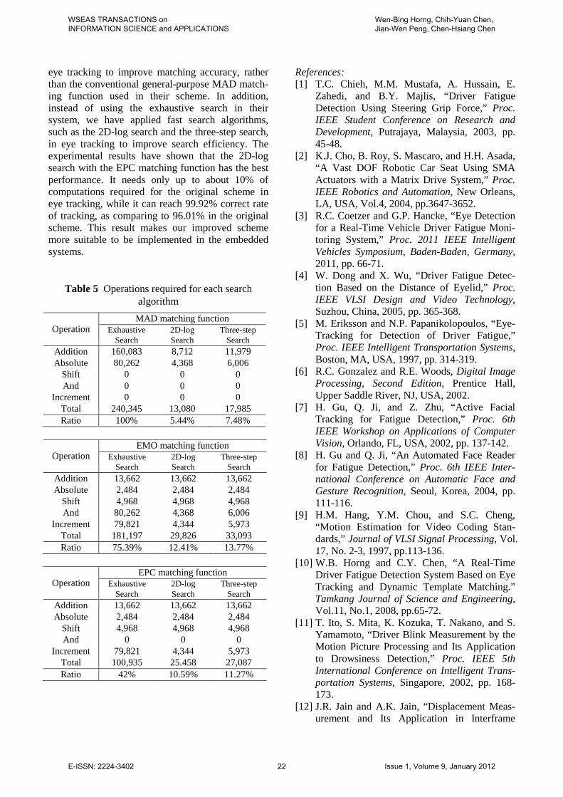
Unlike the three-step search, the 2D-log search has no fixed number of search steps for a given dmax, as shown in Table 4. However, if the center point is the optimal matching point (i.e., zero displacement), there is a lower bound (minimum number) of search steps for the 2D-log search. For dmax = 10, the lower bound is 4; its step size in decreasing order is 5, 3, 2, and 1, the same as that of the three-step search. The number of search points for this case is 21.
Table 4 Results of search steps for the 2D-log search with dmax = 10
Video Left Eye Right Eye Max Min Avg Max Min Avg
1 MAD 11 4 4.69 11 4 4.29 EMO 9 4 4.14 8 4 4.12 EPC 9 4 4.16 8 4 4.16
2 MAD 9 4 4.64 10 4 4.29 EMO 9 4 4.10 8 4 4.11 EPC 10 4 4.18 9 4 4.15
3 MAD 11 4 4.83 11 4 4.38 EMO 10 4 4.15 10 4 4.15 EPC 8 4 4.20 9 4 4.23
4 MAD 10 4 5.35 10 4 4.70 EMO 9 4 4.41 9 4 4.37 EPC 8 4 4.48 9 4 4.59
5 MAD 12 4 5.11 12 4 4.84 EMO 11 4 4.53 9 4 4.54 EPC 9 4 4.61 9 4 4.67
4.2 Analyses Although the fast search algorithms, such as 2D-log and three-step, requires only up to about 7.5% search points of the exhaustive search, they need the overhead of computing edge maps to achieve higher matching accuracy with the new EMO and EPC matching functions.
Suppose that an eye template gt is of width w and height h; it contains n = w × h pixels. Then, the size
of the search region for the eye template gt is of width w + 2dx_max and height h + 2dy_max. Let m be the number of pixels of the search region, i.e., m = (w + 2dx_max) × (h + 2dy_max).
In converting a gray-level image into an edge map, it needs to apply the Sobel horizontal and vertical edge operators to compute the horizontal and vertical gradient values, S1(x, y) and S2(x, y), respectively. For each Sobel edge operator, it re-quires 4 additions, 1 subtraction, and 2 multiplica-tions. Since the required multiplications are simply multiplied by 2, it can be implemented by a left shift for computational efficiency. For the convenience of discussion, subtractions are regarded as additions. Therefore, in order to compute the approximate edge magnitude mag(x, y) of a pixel (x, y) in gt as in Eq. (1), it requires 11 additions, 4 shifts, and 2 absolute value operations; and for computing the edge map et of the eye template gt, it requires 11m additions, 4m shifts, and 2m absolute value operations.
If the MAD matching function is used, it requires n absolute value operations and 2n − 1 additions. If the EMO matching function is used, it only requires n logical AND operations and n − 1 additions. Since the result of a logical AND operation is a binary value, 0 or 1, the addition in the EMO matching function can be implemented by a more efficient increment operation. Similarly, if the EPC matching function is used, it only requires n − 1 increment operations.
A typical eye template in our experiments is of size w = 26 and h = 7. Therefore, the number of pixels in the template is n = 182, and the number pixels in the corresponding search area is m = 1242 for dmax = 10. Table 5 lists the number of operations required for each search algorithm to find the optimal matching points with different matching function, based on the results of Table 3, where the exhaustive, 2D-log, and three-step searches are assumed to require 441, 24 (average upper bound), and 33 (maximum) search points, respectively. It is noted that the 2D-log search with the EPC matching function requires only up to above 10% computa-tions of the original proposal, the exhaustive search with MAD. 5 Conclusion In this paper, we have presented a very efficient eye tracking algorithm to improve Horng-Chen’s driver fatigue detection system. We proposed two new matching functions, EMO and EPC, specifically for
WSEAS TRANSACTIONS on INFORMATION SCIENCE and APPLICATIONS
Wen-Bing Horng, Chih-Yuan Chen, Jian-Wen Peng, Chen-Hsiang Chen
E-ISSN: 2224-3402 21 Issue 1, Volume 9, January 2012
eye tracking to improve matching accuracy, rather than the conventional general-purpose MAD match-ing function used in their scheme. In addition, instead of using the exhaustive search in their system, we have applied fast search algorithms, such as the 2D-log search and the three-step search, in eye tracking to improve search efficiency. The experimental results have shown that the 2D-log search with the EPC matching function has the best performance. It needs only up to about 10% of computations required for the original scheme in eye tracking, while it can reach 99.92% correct rate of tracking, as comparing to 96.01% in the original scheme. This result makes our improved scheme more suitable to be implemented in the embedded systems.
Table 5 Operations required for each search algorithm
Operation MAD matching function
Exhaustive Search
2D-log Search
Three-step Search
Addition 160,083 8,712 11,979 Absolute 80,262 4,368 6,006
Shift 0 0 0 And 0 0 0
Increment 0 0 0 Total 240,345 13,080 17,985 Ratio 100% 5.44% 7.48%
Operation EMO matching function
Exhaustive Search
2D-log Search
Three-step Search
Addition 13,662 13,662 13,662 Absolute 2,484 2,484 2,484
Shift 4,968 4,968 4,968 And 80,262 4,368 6,006
Increment 79,821 4,344 5,973 Total 181,197 29,826 33,093 Ratio 75.39% 12.41% 13.77%
Operation EPC matching function
Exhaustive Search
2D-log Search
Three-step Search
Addition 13,662 13,662 13,662 Absolute 2,484 2,484 2,484
Shift 4,968 4,968 4,968 And 0 0 0
Increment 79,821 4,344 5,973 Total 100,935 25.458 27,087 Ratio 42% 10.59% 11.27%
References: [1] T.C. Chieh, M.M. Mustafa, A. Hussain, E.
Zahedi, and B.Y. Majlis, “Driver Fatigue Detection Using Steering Grip Force,” Proc. IEEE Student Conference on Research and Development, Putrajaya, Malaysia, 2003, pp. 45-48.
[2] K.J. Cho, B. Roy, S. Mascaro, and H.H. Asada, “A Vast DOF Robotic Car Seat Using SMA Actuators with a Matrix Drive System,” Proc. IEEE Robotics and Automation, New Orleans, LA, USA, Vol.4, 2004, pp.3647-3652.
[3] R.C. Coetzer and G.P. Hancke, “Eye Detection for a Real-Time Vehicle Driver Fatigue Moni-toring System,” Proc. 2011 IEEE Intelligent Vehicles Symposium, Baden-Baden, Germany, 2011, pp. 66-71.
[4] W. Dong and X. Wu, “Driver Fatigue Detec-tion Based on the Distance of Eyelid,” Proc. IEEE VLSI Design and Video Technology, Suzhou, China, 2005, pp. 365-368.
[5] M. Eriksson and N.P. Papanikolopoulos, “Eye-Tracking for Detection of Driver Fatigue,” Proc. IEEE Intelligent Transportation Systems, Boston, MA, USA, 1997, pp. 314-319.
[6] R.C. Gonzalez and R.E. Woods, Digital Image Processing, Second Edition, Prentice Hall, Upper Saddle River, NJ, USA, 2002.
[7] H. Gu, Q. Ji, and Z. Zhu, “Active Facial Tracking for Fatigue Detection,” Proc. 6th IEEE Workshop on Applications of Computer Vision, Orlando, FL, USA, 2002, pp. 137-142.
[8] H. Gu and Q. Ji, “An Automated Face Reader for Fatigue Detection,” Proc. 6th IEEE Inter-national Conference on Automatic Face and Gesture Recognition, Seoul, Korea, 2004, pp. 111-116.
[9] H.M. Hang, Y.M. Chou, and S.C. Cheng, “Motion Estimation for Video Coding Stan-dards,” Journal of VLSI Signal Processing, Vol. 17, No. 2-3, 1997, pp.113-136.
[10] W.B. Horng and C.Y. Chen, “A Real-Time Driver Fatigue Detection System Based on Eye Tracking and Dynamic Template Matching.” Tamkang Journal of Science and Engineering, Vol.11, No.1, 2008, pp.65-72.
[11] T. Ito, S. Mita, K. Kozuka, T. Nakano, and S. Yamamoto, “Driver Blink Measurement by the Motion Picture Processing and Its Application to Drowsiness Detection,” Proc. IEEE 5th International Conference on Intelligent Trans-portation Systems, Singapore, 2002, pp. 168-173.
[12] J.R. Jain and A.K. Jain, “Displacement Meas-urement and Its Application in Interframe
WSEAS TRANSACTIONS on INFORMATION SCIENCE and APPLICATIONS
Wen-Bing Horng, Chih-Yuan Chen, Jian-Wen Peng, Chen-Hsiang Chen
E-ISSN: 2224-3402 22 Issue 1, Volume 9, January 2012

Image Coding,” IEEE Transactions on Com-munications, Vol. COM-29, No. 12, 1981, pp.1799-1808.
[13] B.T. Jap, S. Lal, P. Fischer, and E. Bekiaris, “Using EEG Spectral Components to Assess Algorithms for Detecting Fatigue,” Expert Systems with Applications, Vol. 36, No. 2, 2009, pp. 2352-2359.
[14] Q. Ji, Z. Zhu, and P. Lan, “Real-Time Non-intrusive Monitoring and Prediction of Driver Fatigue,” IEEE Transactions on Vehicular Technology, Vol.53, No.4, 2004, pp.1052-1068.
[15] T. Koga, K. Iinuma, A. Hirano, Y. Iijima, and T. Ishiguro, “Motion-Compensated Interframe Coding for Video Conferencing,” Proc. Na-tional Telecommunications Conference, New Orleans, LA, USA, 1981, pp.G5.3.1-G5.3.5.
[16] M.A. Recarte and L.M. Nunes, “Effects of Verbal and Spatial-Imagery Tasks on Eye Fixa-tions while Driving,” Journal of Experimental Psychology: Applied, Vol.6, No.1, 2000, pp.31-43.
[17] D. Shinar, Psychology on the Road, John Wiley & Sons, Danvers, MA, USA, 1979.
[18] S. Singh and N.P. Papanikolopoulos, “Monitor-ing Driver Fatigue Using Facial Analysis Techniques,” Proc. IEEE Intelligent Transpor-tation Systems, Tokyo, Japan, 1999, pp. 314-318.
[19] Smart Motorist, Inc., “Driver Fatigue is an Important Cause of Road Crashes,” http://www. smartmotorist.com/traffic-and-safety-guideline/ driver-fatigue-is-an-important-cause-of-road-crashes.html (visited, 2011/08/22).
[20] A. Vuckovic, D. Popovic, and V. Radivojevic, “Artificial Neural Network for Detecting Drowsiness from EEG Recordings,” Proc. IEEE Seminar on Neural Network Applications in Electrical Engineering, Belgrade, Yugosla-via, 2002, pp. 155-158.
[21] H. Wang, L.B. Zhou, and Y. Ying, “A Novel Approach for Real Time Eye State Detection in Fatigue Awareness System,” Proc. 2010 IEEE International Conference on Robotics Automa-tion and Mechatronics, 2010, Singapore, pp. 528-532.
[22] R.B. Wang, K.Y. Guo, S.M. Shi, and J.W. Chu, “A Monitoring Method of Driver Fatigue Behavior Based on Machine Vision,” Proc. 2003 IEEE Intelligent Vehicles Symposium, Columbus, Ohio, USA, 2003, pp. 110-113.
[23] R.B. Wang, L. Guo, B. Tong, and L. Jin, “Monitoring Mouth Movement for Driver Fatigue or Distraction with One Camera,” Proc. 7th IEEE International Conference on Intelli-
gent Transportation Systems, Washington, D.C., USA, 2004, pp. 314-319.
[24] B.J. Wilson and T.D. Bracewell, “Alertness Monitor Using Neural Networks for EEG Analysis,” Proc. 2000 IEEE Signal Processing Society Workshop on Neural Networks for Signal Processing, Sydney, Australia, 2000, Vol. 2, pp.814-820.
[25] J.H. Yang, Z.H. Mao, L. Tijerina, T. Pilutti, J.F. Coughlin, and E. Feron, “Detection of Driver Fatigue Caused by Sleep Deprivation,” IEEE Transactions on Systems, Man, and Cybernet-ics-Part A: Systems and Humans, Vol. 39, No. 4, 2009, pp. 694-705.
[26] K.P. Yao, W.H. Lin, C.Y. Fang, J.M. Wang, S.L. Chang, and S.W. Chen, “Real-Time Vi-sion-Based Driver Drowsiness/Fatigue Detec-tion System,” Proc. IEEE 71st Vehicular Technology Conference, Taipei, Taiwan, 2010, pp. 1-5.
[27] Z. Zhu and Q. Ji, “Real-Time and Non-intrusive Driver Fatigue Monitoring,” Proc. 7th IEEE International Conference on Intelligent Transportation Systems, Washington, D.C., USA, 2004, pp.657-662.
WSEAS TRANSACTIONS on INFORMATION SCIENCE and APPLICATIONS
Wen-Bing Horng, Chih-Yuan Chen, Jian-Wen Peng, Chen-Hsiang Chen
E-ISSN: 2224-3402 23 Issue 1, Volume 9, January 2012