improved understanding of explosive–rock - scielo · mining company by protecting the long-term...
TRANSCRIPT

Journal
Paper
Introduction
Blasting and rock engineering are comple-mentary disciplines. Whereas blasting isfocused on the removal of the rock within theexcavation to facilitate production, rockengineers are required to support theexcavation to ensure the short-term safety ofthe miners and maintain the viability of themining company by protecting the long-termstability of the entire mine. Proper blast designcan be used to facilitate the work of both theblasters and the rock engineers. Any reductionin damage to the excavation limits theoverbreak and hence minimizes the materialthat must be removed, and at the same timeprevents unravelling of the rock surroundingthe excavation (Sellers, 2011). In both
disciplines there is a need for the ability topredict the effect of blasting on the rock mass.
The realization of the importance ofincluding the proper dynamic rock mechanicslinked with accurate detonation physics intoblast design software resulted in an interna-tional group of mining and explosivecompanies combining with the University ofQueensland and Itasca Consulting Group toform a research group to develop the hybridstress blasting model (HSBM). The termhybrid refers to the way that a combination ofnumerical methods is used to model thevarious blast processes. Once the model hasbeen validated against realistic blasts, it can beapplied with more confidence to modelling ofunknown situations. For the HSBM projectteam, the validation process must answer twomain questions. Firstly, can the outcome of theblast be predicted before the blaster pushes thefiring button? Secondly, if changes need to bemade to the design, can the model predictthese changes accurately? Validation of thecode to date has focused on breakage andfragmentation in laboratory-scale experimentsand larger concrete cube blasts (Onderra et al.,2009, Sellers et al., 2009, Sellers et al., 2010,Furtney et al., 2011), with some shortcomingsin terms of the induced particle velocities thatrequired reduced strengths to match theexperimental fracturing. Subsequent tochanges to the model formulation, simulationsof well-instrumented field tests in kimberlitehave been carried out, and measured andpredicted face velocities, peak particle
Improved understanding of explosive–rockinteractions using the hybrid stress blastingmodelby E. Sellers*, J. Furtney†, I. Onederra‡, and G. Chitombo‡
SynopsisSince 2001, the Hybrid Stress Blast Model (HSBM) project membershave developed a software suite to model the complete blastingprocess from non-ideal detonation to muck pile formation. Topreserve the physics and improve solution time, the breakageengine uses a combination of analytical models and 2D axisym-metric finite differences to model near-field crushing, coupled to 3Ddiscrete lattice fracturing and distinct element numerical methods tomodel throw and muck pile development. The model has beenvalidated by comparison with laboratory and field tests inkimberlite. Multiple blasthole simulations are used to demonstratehow changes to blasting parameters can influence downstreamefficiencies. Case studies of wall control blasting show that thepresplit design must balance the two opposing effects of increaseddamage with increased charge and decreasing attenuation of theseismic waves with decreasing charge. Modelling of decoupledexplosives needs further development. Reducing the charge towardsthe back of the trim blast results in a much more significantdecrease in back damage than altering the timing. The modeldemonstrates how separation along the weaker planes in a jointedrock can coarsen the fragmentation, leading to inefficient benefi-ciation, and extends the damage to a distance of at least twice theburden behind from the blasthole, severely compromising the wallstability.
Keywordsblasting, modelling, discrete element method.
* AEL Mining Services, Johannesburg, South Africa.† Itasca Consulting Group, Minneapolis, MN, USA.‡ SMI, University of Queensland, Brisbane, Australia.© The Southern African Institute of Mining and
Metallurgy, 2012.ISSN 2225-6253. This paper wasfirst presented at the, Southern HemisphereInternational Rock Mechanics Symposium(SHIRMS) 2012, 15–17 May 2012, Sun City,South Africa.
721The Journal of The Southern African Institute of Mining and Metallurgy VOLUME 112 AUGUST 2012 �

Improved understanding of explosive–rock interactions using the hybrid stress blasting
velocities, and fragmentation agree remarkably well usingvery generic rock and blast input parameters (Sellers et al.,2012). That modelling is briefly described here as abackground to demonstrate the model’s capabilities.
Recent improvements in the analysis efficiency coupledwith the good agreement with the field tests have permittedthe modelling of larger-scale production blasts to provide theblaster with an understanding of the effect of changing blastparameters and the rock engineer with ability to predict backdamage to improve the wall stability of large open pits. Thispaper concentrates on describing some situations thatdemonstrate how the numerical model has improved ourunderstanding of the dynamics of rock fracturing and particleinteractions during surface blasting processes, and showshow subtle changes in the blasting parameters can improveor compromise downstream beneficiation processes.
Model formulation
The HSBM project has extended over the past ten years, andhas required a number of independent computer codes to becoupled together to achieve the project objectives ofmaintaining the physical processes and yet providing a modelthat is quick and robust enough to produce results forpractical field application. The full details of the numericalcode are complex and have required a number of papers for acomplete description. A summary of these can be found inFurtney et al. (2009, 2011). For completeness, only a verybrief summary of how the model is implemented is presentedhere. The relevant steps are shown schematically in Figure 1.Characterization of the explosive in terms of density, energyrelease, reaction extent, product equation of state (EoS), andvelocity of detonation (VoD) is required as the first step ofthe modelling process to achieve a detailed pressure loading.These detonation aspects of the HSBM project are describedin detail in Braithwaite and Sharpe (2009). A non-idealdetonation code, Vixen2009, a component of the HSBMsoftware suite, determines these parameters using a semi-analytical approach and transfers them as inputs to thebreakage engine (called Blo-Up2). The explosive isrepresented on a coarser scale as a special constitutivebehaviour in the central zones of an axisymmetric continuumrepresentation based on FLAC (Itasca, 2008). The axisym-metric approximation is used instead of a full three-dimensional approach to save computer time with therealization that the detonation-induced loading is essentially
axisymmetric for the duration of the detonation. Instead ofthe fine grid, full detonation, fluid dynamics solution thattakes weeks to run, a coarse grid programmed burnalgorithm (Cundall and Detournay, 2008) is used to simulatethe detonation process, and the expansion and axial flow ofthe detonation products (step 2) by releasing energy intocoarse finite- difference zones representing explosive basedon a predetermined velocity of detonation, calculated byVixen2009. Beyond the central explosive zones a continuumMohr-Coulomb material constitutive law represents thecrushing and energy loss of the near-field rock (step 3).
The FLAC zones representing the explosive and near-fieldrock are coupled to a 3D lattice-type discrete element method(Furtney et al., 2009). This is a simplification of the standardDEM calculation (Potyondy and Cundall, 2004), which takestoo long to solve and has functionality that is not needed forblast fracturing that is induced mainly by tensile stressesoutside the compressive near-field zone. The lattice methodapplies forces to point masses, which have only translationaldegrees of freedom, and the connecting springs have a rate-dependent tensile breaking strength. The radial fracturingoccurring away from the borehole (step 4) is primarilytensile-mode failure, which still is represented well with thelattice-model simplifications. The compromise entailed in thisspeed-up is the poor representation of shear wavetransmission, though this can be included if desired. Latticenodes that overlap FLAC zones are velocity-controlled by themovement in the FLAC zones. The lattice nodes thencontribute forces back to the FLAC zones. This mechanismprovides full coupling between the lattice region and thenear-field representation.
The mechanical calculation is fully coupled to a simplifiedgas flow model representing the high-pressure reactionproduct gas. The expanding gas applies a force to thefragments contributing the throw. Finally (step 5), parts ofthe lattice that are completely broken into fragments interactas DEM particles (Potyondy and Cundall, 2004) with contactdetection and temporary contact springs that are used tomodel how the flying particles interact and settle to form thefinal muck pile.
Validation
More recently, significant work has been undertaken by theproject sponsors and researchers to design and evaluate aseries of validation cases for this new technology. It is
�
722 AUGUST 2012 VOLUME 112 The Journal of The Southern African Institute of Mining and Metallurgy
Figure 1—A schematic of the model formulation indicating the analytical input into the 2D finite difference grid, coupled to a 3D lattice that breaks intointeracting particles (Furtney et al., 2009)
Fragment 1
Slave node(a)
1086420
0 400 800 1200 1600z (mm)
P (G
Pa)
Boundary Condition
StemmingExplosiveRock
Fragment 2
Temporary ContactVixen 2009
Blo-Up2

important to note that considerable variation is reported inthe results from ostensibly identical physical experiments, sothe expectation of close agreement between a numericalsimulation and a single experimental result is unreasonable.Sellers et al. (2012) presented validation studies based onfield-scale single- and multiple-hole blast tests performed atthe start of the HSBM project, which are briefly describedhere to demonstrate the capabilities of the model and set thescene for later modelling.
Given enough effort, any model can be calibrated toexactly reproduce observations, but it is difficult to reproduceboth the magnitude and trends of observations with a singleset of inputs, especially if these are generic. Thus, two testswith different collar burdens (2 m and 6 m) are used toevaluate whether the model can reproduce the correct trends.One comparison between the face movement of the actualtests and the model predictions is shown in Figure 2 at 480 ms after initiation. The bench height used was 10 m andthe face slope is set to 80 degrees, though blastholes arevertical. The rock properties were selected to be typical for thehard kimberlite and in the general range of the testedproperties. The Young’s modulus is 30 GPa, density is 2500kg/m3, unconfined compression strength is 70 MPa, tensilestrength is 5 MPa, Poisson’s ratio is 0.22, damping is 0.1,and the friction angle is set to 25°. The explosive is ANFOwith a velocity of detonation of 4110 m/s. These propertiesare sufficiently representative to evaluate how well the modelworks without going through a detailed and exactingcalibration procedure that would not be available in anypractical blasting scenario where rock test data is usually notavailable.
The model results for the same time also indicate thechange in rock response with decreasing burden. Figure 2ashows the cratering effect with no face movement at a 6 mburden, whereas Figure 2b demonstrates similar degree ofdynamic face heave at the 2 m burden. A quantitativecomparison is always important, and the face velocitypredicted for the 2 m burden model is about 10 m/s, which isslightly higher than the 6.4 m/s observed in the tests.However, the ability of the model to predict the magnitude ofthe observations is remarkable.
Prediction of blast outcomes
With the knowledge that the model can represent the trendscorrectly, it is now possible to produce larger-scale models todemonstrate how the model would inform the blaster howalterations in the blasting parameters could affect the qualityof the blast outcomes. There is ample evidence that the typeof initiating system and timing alters the blast outcome,depending on the scatter in timing (Cunningham, 2005). Oneof the easier parameters to change is the powder factor,measured as the mass of explosive for a given rock volume,which can be modified by changing the hole diameter or thedistance between adjacent holes (burden).
Two larger models were used to highlight the effect ofchanging firstly the burden and spacing and secondly thehole diameter. The models (shown in Figure 3) use 15 and60 holes, respectively. The 15-hole model runs overnight ona six-core PC and the 60-hole model takes 4 days of runtime. The decrease of powder factor by increasing the burdenand spacing (keeping the ratio between them constant)
Improved understanding of explosive–rock interactions using the hybrid stress blastingJournal
Paper
723The Journal of The Southern African Institute of Mining and Metallurgy VOLUME 112 AUGUST 2012 �
Figure 2—Heave profiles at 480 ms from high-speed video and model (a) 6 m burden and (b) 2m burden
Crater formation
#4 - 480ms #4 - 480ms
Figure 3—Two larger blast models (a) 15 blastholes and (b) 60 blastholes

Improved understanding of explosive–rock interactions using the hybrid stress blasting
significantly decreases the throw of the muck pile, as shownin Figure 4. The higher powder factor results in more throwand a flatter muck pile, as would be preferred for smallerexcavating equipment. Larger shovels would prefer the moresteeply heaped muck pile associated with the lower powderfactors. The lower powder factor causes a less uniformfragmentation distribution and more large fragments thatwould be detrimental to smaller loading equipment. When thehole diameter changes, the distribution of the explosivewithin the rock mass is altered as a larger hole will requirelonger stemming, forcing the explosive mass further awayfrom the surface. The burden also needs to increase, with theresult that heave is diminished as is seen by comparingFigure 4a with Figure 5, where the hole diameter is increasedfrom 165 mm to 250 mm. These subtleties are not alwaysappreciated by mine production personnel and can adverselyaffect production. For example, the decision to improvedrilling efficiency could severely compromise loadingprocesses if the fragmentation and muck pile shape changesbeyond the capability of the existing excavating equipment.By differently colouring the fragments derived from each rowof holes, as shown in Figure 6, the model demonstrates thecomplexity of the mixing regime within the muck pile due tothe interrelationship between the hole timing and the time ittakes for fragments to fall to ground at a given ejectionvelocity. This complex interlayering is not intuitive and is notpredicted by simpler blasting models. Misunderstanding ofthis is common and can lead to major inefficiencies in mines,
where it is vital to distinguish between ore and waste tominimize dilution in the plant or limit valuable ore being sentto the waste dump (e.g. Wade, 2012)
Wall control case studies
Having studied how the model can predict blast performance,it is useful to consider how it can contribute to the rockengineer’s need to determine the damage associated withblasting. Two case studies are used to provide realisticscenarios for this analysis. Firstly, project interventionssignificantly improved the condition of the final walls in veryweak kimberlite rock with a compressive strength that rangesfrom 8 MPa to 60 MPa, as shown in Figure 7 (Oageng, et al.,2008). These properties are lower than the those of thekimberlite used in the model as specified earlier. In this casethe presplitting was originally done using set of 50 mmcartridges. Little improvement was seen when the 50 mmcartridges were spaced along the hole, and the best result wasfound when the trim blast timing was changed and theexplosive distribution was limited to a line of cartridges of 25 mm diameter. Secondly, in similar conditions at the openpit, where the blasts described were performed, the mineused 38 mm and 32 mm cartridges distributed along thepresplit holes in stronger kimberlite (Naidoo, 2006). In bothcases many expensive tests were also required to evaluatedifferent blasting options, which could be avoided if themodel can be used to discard unsuitable options.
Wall control blasting techniques involve firstly creating atensile presplit along the line of the final wall with closelyspaced blastholes that contain low quantities of explosive,usually decoupled from the side of the blast holes. Then,production blasts are taken to remove rock until only threelines of holes remain in front of the presplit. The blasting ofthese last three lines is known as a trim blast and requiresspecial care in the selection of blasting parameters to producegood wall control by limiting the explosive energytransmission and associated damage in the final wall.
�
724 AUGUST 2012 VOLUME 112 The Journal of The Southern African Institute of Mining and Metallurgy
Figure 4—Effect of powder factor on muck pile shapetwo seconds afterblast initiation (a) 1.2 kg/m3 (b) 0.72 kg/m3 and (c) 0.44 kg/m3
Figure 5—Effect of hole diameter at constant powder factor for a 250 mm hole diameter
Figure 6—Section through muck pile with high powder factor showingmixing of different burdens
Figure 7—Final walls of 15 m high benches for soft kimberlite rock (a) before and (b) after the project (Oageng, et al. 2008)
(a) (b)
(a)
(b)
(c)

The effect of presplit charge diameter on walldamage
The subsequent modelling loosely follows the blastingpractices in these two studies to demonstrate how the choiceof blast design parameters can affect the wall stability. Forthis paper we have selected the same model properties asdescribed earlier and explosive properties equivalent to 50 mm or 38 mm cartridges of emulsion distributed along theholes at 1 m spacing. The model is shown in Figure 8 andhas a portion excavated (shown in orange) to simulate theface of the previous trim blast. The model uses 19 presplitholes fired simultaneously, and then the trim blast holes withan explosive model simulating ANFO are fired 10 ms laterfrom the front corner with a timing of 75 ms along rows and42 ms between rows.
A section though the model after 200 ms is shown inFigure 9 for three different cases of no presplit, 50 mmcartridges, and 38 mm cartridges in a 165 mm blasthole. Thecase without presplit shows excessive back-break. When thepresplit is taken with 50 mm cartridges, there is significantdamage from the presplit itself though there is no furtherdamage from the trim blast. This is similar to the situationsdescribed in the case studies. Once the cartridge diameter isreduced to 38 mm, then the split forms cleanly and there islimited damage (incomplete fractures) formed into theremaining highwall. The presplit shows more damage thanexpected, and this aspect is being addressed by the HSBMresearchers.
Many authors e.g. Onederra and Esen (2004) and Bye etal. (2005) relate peak particle velocity to damage. In order todemonstrate the effect of the presplit on the particle velocity,the cumulative energy equivalence is calculated from thevelocity squared:
[1]
where VX and VY are the horizontal particle velocities perpen-dicular and parallel to the face, respectively, at the pointshown in Figure 8. Figure 10 shows that there is a significantattenuation of the energy by the 50 mm presplit and less by
the 38 mm split. Considering that the damage is less with the38 mm presplit, design must maintain a balance between thedamage caused by the split and the damage caused by theparticle velocity. This needs to be compared to in situmeasurements of particle velocity and damage.
The effect of blast timing in the trim blast on wallstability
The timing in the case study by Oageng et al. (2008) wasaltered to reduce the peak particle velocity acting towards theback by changing the timing contours to flatten the directionof heave and hence attempt to direct the particle velocity atflatter angle to the highwall. The two cases tested are shownin Figure 11, with Figure 11a showing the timing for the casewith 33 ms between holes and 100 ms between rows, andFigure 11b showing the case with a longer time of 75 msbetween the holes in the row and a shorter time of 42 msbetween rows. In both cases, the presplit was modelled as apre-exiting joint. The aim of this modelling study was toinvestigate whether the timing really influences the peakparticle velocity significantly.
The arrows in Figure 11 indicate the conventionalunderstanding of blast throw as being predominantly in thedirection perpendicular to the timing contours. Slower timingalong the free face leads to a more oblique heave directioneffectively shearing the rock off the presplit face (Figure 11b)and hence supposedly inducing less reaction back into the
Improved understanding of explosive–rock interactions using the hybrid stress blastingJournal
Paper
The Journal of The Southern African Institute of Mining and Metallurgy VOLUME 112 AUGUST 2012 725 �
Figure 8—Model of trim blast Figure 10—Equivalent energy plot to show the effect of presplitting
Position of PPVmeasurement
Previous benchexcavated
Figure 9—Slice through model in plan after 200 ms (blast time) (a) nopresplit, (b) presplit with 55 mm diameter decoupled charge, and (c)with 38 mm decoupled charges
Improved understanding of explosive–rock interactions using the hybrid stress blasting
remaining rock mass. The fracture patterns in sectionproduced by the model in Figure 12 indicate similar trends inthe direction of heave. However, the question of final wallstability relates to what happens behind the blast.
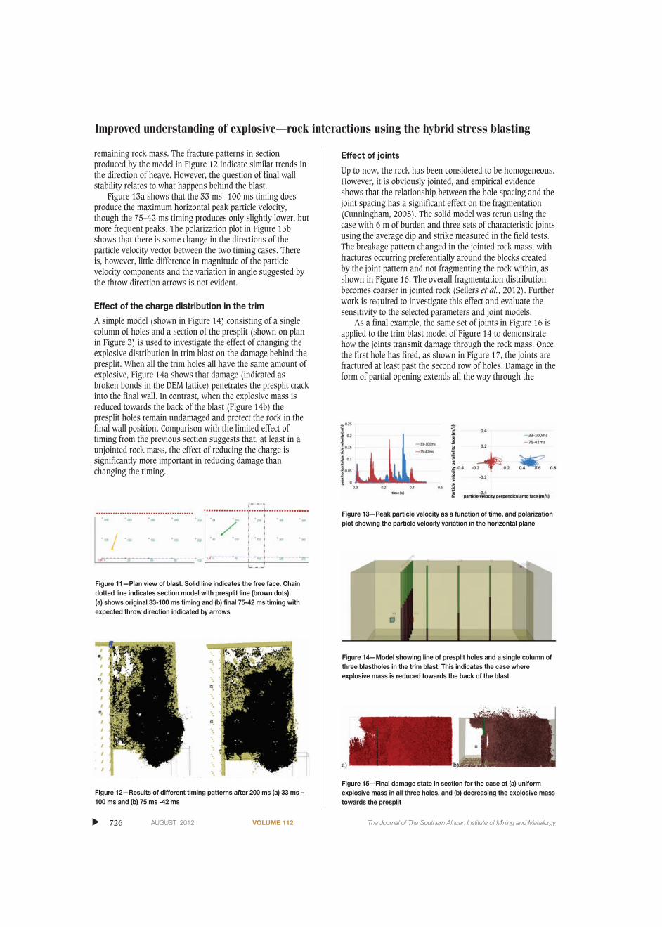
Figure 13a shows that the 33 ms -100 ms timing doesproduce the maximum horizontal peak particle velocity,though the 75–42 ms timing produces only slightly lower, butmore frequent peaks. The polarization plot in Figure 13bshows that there is some change in the directions of theparticle velocity vector between the two timing cases. Thereis, however, little difference in magnitude of the particlevelocity components and the variation in angle suggested bythe throw direction arrows is not evident.
Effect of the charge distribution in the trim
A simple model (shown in Figure 14) consisting of a singlecolumn of holes and a section of the presplit (shown on planin Figure 3) is used to investigate the effect of changing theexplosive distribution in trim blast on the damage behind thepresplit. When all the trim holes all have the same amount ofexplosive, Figure 14a shows that damage (indicated asbroken bonds in the DEM lattice) penetrates the presplit crackinto the final wall. In contrast, when the explosive mass isreduced towards the back of the blast (Figure 14b) thepresplit holes remain undamaged and protect the rock in thefinal wall position. Comparison with the limited effect oftiming from the previous section suggests that, at least in aunjointed rock mass, the effect of reducing the charge issignificantly more important in reducing damage thanchanging the timing.
Effect of joints
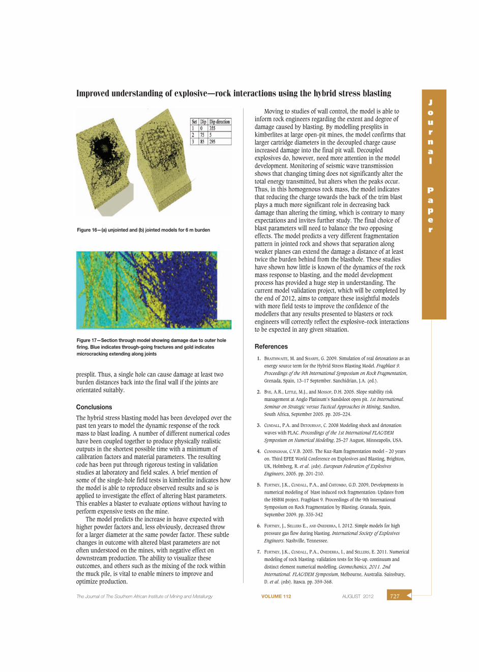
Up to now, the rock has been considered to be homogeneous.However, it is obviously jointed, and empirical evidenceshows that the relationship between the hole spacing and thejoint spacing has a significant effect on the fragmentation(Cunningham, 2005). The solid model was rerun using thecase with 6 m of burden and three sets of characteristic jointsusing the average dip and strike measured in the field tests.The breakage pattern changed in the jointed rock mass, withfractures occurring preferentially around the blocks createdby the joint pattern and not fragmenting the rock within, asshown in Figure 16. The overall fragmentation distributionbecomes coarser in jointed rock (Sellers et al., 2012). Furtherwork is required to investigate this effect and evaluate thesensitivity to the selected parameters and joint models.
As a final example, the same set of joints in Figure 16 isapplied to the trim blast model of Figure 14 to demonstratehow the joints transmit damage through the rock mass. Oncethe first hole has fired, as shown in Figure 17, the joints arefractured at least past the second row of holes. Damage in theform of partial opening extends all the way through the
�
726 AUGUST 2012 VOLUME 112 The Journal of The Southern African Institute of Mining and Metallurgy
Figure 11—Plan view of blast. Solid line indicates the free face. Chaindotted line indicates section model with presplit line (brown dots). (a) shows original 33-100 ms timing and (b) final 75-42 ms timing withexpected throw direction indicated by arrows
Figure 12—Results of different timing patterns after 200 ms (a) 33 ms –100 ms and (b) 75 ms -42 ms
Figure 13—Peak particle velocity as a function of time, and polarizationplot showing the particle velocity variation in the horizontal plane
Figure 14—Model showing line of presplit holes and a single column ofthree blastholes in the trim blast. This indicates the case whereexplosive mass is reduced towards the back of the blast
Figure 15—Final damage state in section for the case of (a) uniformexplosive mass in all three holes, and (b) decreasing the explosive masstowards the presplit
presplit. Thus, a single hole can cause damage at least twoburden distances back into the final wall if the joints areorientated suitably.
Conclusions
The hybrid stress blasting model has been developed over thepast ten years to model the dynamic response of the rockmass to blast loading. A number of different numerical codeshave been coupled together to produce physically realisticoutputs in the shortest possible time with a minimum ofcalibration factors and material parameters. The resultingcode has been put through rigorous testing in validationstudies at laboratory and field scales. A brief mention ofsome of the single-hole field tests in kimberlite indicates howthe model is able to reproduce observed results and so isapplied to investigate the effect of altering blast parameters.This enables a blaster to evaluate options without having toperform expensive tests on the mine.
The model predicts the increase in heave expected withhigher powder factors and, less obviously, decreased throwfor a larger diameter at the same powder factor. These subtlechanges in outcome with altered blast parameters are notoften understood on the mines, with negative effect ondownstream production. The ability to visualize theseoutcomes, and others such as the mixing of the rock withinthe muck pile, is vital to enable miners to improve andoptimize production.
Moving to studies of wall control, the model is able toinform rock engineers regarding the extent and degree ofdamage caused by blasting. By modelling presplits inkimberlites at large open-pit mines, the model confirms thatlarger cartridge diameters in the decoupled charge causeincreased damage into the final pit wall. Decoupledexplosives do, however, need more attention in the modeldevelopment. Monitoring of seismic wave transmissionshows that changing timing does not significantly alter thetotal energy transmitted, but alters when the peaks occur.Thus, in this homogenous rock mass, the model indicatesthat reducing the charge towards the back of the trim blastplays a much more significant role in decreasing backdamage than altering the timing, which is contrary to manyexpectations and invites further study. The final choice ofblast parameters will need to balance the two opposingeffects. The model predicts a very different fragmentationpattern in jointed rock and shows that separation alongweaker planes can extend the damage a distance of at leasttwice the burden behind from the blasthole. These studieshave shown how little is known of the dynamics of the rockmass response to blasting, and the model developmentprocess has provided a huge step in understanding. Thecurrent model validation project, which will be completed bythe end of 2012, aims to compare these insightful modelswith more field tests to improve the confidence of themodellers that any results presented to blasters or rockengineers will correctly reflect the explosive–rock interactionsto be expected in any given situation.
References
1. BRAITHWAITE, M. and SHARPE, G. 2009. Simulation of real detonations as an
energy source term for the Hybrid Stress Blasting Model. Fragblast 9.Proceedings of the 9th International Symposium on Rock Fragmentation,
Grenada, Spain, 13–17 September. Sanchidrian, J.A. (ed.).
2. BYE, A.R., LITTLE, M.J., and MOSSOP, D.H. 2005. Slope stability risk
management at Anglo Platinum’s Sandsloot open pit. 1st International.Seminar on Strategic versus Tactical Approaches in Mining, Sandton,
South Africa, September 2005. pp. 205–224.
3. CUNDALL, P.A. and DETOURNAY, C. 2008 Modeling shock and detonation
waves with FLAC. Proceedings of the 1st International FLAC/DEMSymposium on Numerical Modeling, 25–27 August, Minneapolis, USA.
4. CUNNINGHAM, C.V.B. 2005. The Kuz-Ram fragmentation model – 20 years
on. Third EFEE World Conference on Explosives and Blasting, Brighton,
UK, Holmberg, R. et al. (eds). European Federation of ExplosivesEngineers, 2005. pp. 201-210.
5. FURTNEY, J.K., CUNDALL, P.A., and CHITOMBO, G.D. 2009, Developments in
numerical modeling of blast induced rock fragmentation: Updates from
the HSBM project. Fragblast 9. Proceedings of the 9th International
Symposium on Rock Fragmentation by Blasting. Granada, Spain,
September 2009. pp. 335-342
6. FURTNEY, J., SELLERS E., AND ONEDERRA, I. 2012. Simple models for high
pressure gas flow during blasting. International Society of Explosives
Engineers. Nashville, Tennessee.
7. FURTNEY, J.K., CUNDALL, P.A., ONEDERRA, I., and SELLERS, E. 2011. Numerical
modeling of rock blasting: validation tests for blo-up. continuum and
distinct element numerical modelling. Geomechanics, 2011. 2nd
International. FLAC/DEM Symposium, Melbourne, Australia. Sainsbury,
D. et al. (eds). Itasca. pp. 359-368.
Improved understanding of explosive–rock interactions using the hybrid stress blastingJournal
Paper
The Journal of The Southern African Institute of Mining and Metallurgy VOLUME 112 AUGUST 2012 727 �
Figure 16—(a) unjointed and (b) jointed models for 6 m burden
Figure 17—Section through model showing damage due to outer holefiring. Blue indicates through-going fractures and gold indicatesmicrocracking extending along joints

Improved understanding of explosive–rock interactions using the hybrid stress blasting
8. ITASCA CONSULTING GROUP, INC. 2008. LAC (Fast Lagrangian Analysis of
Continua), Version 6.0. Minneapolis, USA.
9. NAIDOO, V. 2006. Presplit project. Workshop for Explosive Engineers, AEL
Mining.
10. OAGENG, K., JOSEPH, R.O., and MUNYADZWE, I. 2008. Perimeter control at
Orapa Diamond Mine. Surface Mining Conference. The Southern AfricanInstitute of Mining and Metallurgy. pp. 137–152.
11. ONEDERRA, I. and ESEN, S. 2004. An alternative approach to determine the
Holmberg–Persson constants for modelling near field peak particle velocity
attenuation. Fragblast, vol. 8, no. 2. pp. 61–84.
12. ONEDERRA, I. AND GROBLER, H. 2004 Single and multiple hole blasting tests.
Report submitted to the HSBM Project.
13. ONEDERRA, I., CUNDALL, P., FURTNEY J., and CHITOMBO, G. 2009, Towards a
complete validation of the lattice scheme in the Hybrid Stress Blasting
Model (HSBM). Fragblast 9. Proceedings of the 9th InternationalSymposium on Rock Fragmentation by Blasting, Granada, Spain,
September 2009. pp. 343-351
14. POTYONDY, D.O. and CUNDALL, P.A. 2004. A bonded-particle model for rock.
International Journal of Rock Mechanics and Mining Sciences, vol. 41.
pp. 1329–1364.
15. ROGERS, W., KANCHIBOTLA, S.S., TORDOIR, A., AKO, S., ENGMANN, E., and
BISIAUX, B. 2012. Understanding blast movement and its impacts on grade
control at Ahafo Gold Mine in Ghana. International Society of ExplosivesEngineers. Nashville, Tennessee.
16. SELLERS, E., FURTNEY, J., and ONEDERRA, I. 2012. Field-scale modelling of
blasting in kimberlite using the Hybrid Stress Blasting Model.
International Society of Explosive Engineers. Nashville, Tennessee.
17. SELLERS, E., KOTZE, M., DIPENAAR, L., and RUEST, M. 2009. Large scale
concrete cube blasts for the HSBM model,Sanchidrian, J.A. (ed). Fragblast9. Proceedings of the 9th International. Symposium on RockFragmentation, Granada, Spain, 13-17 September.
18. SELLERS, E.J. 2011 Controlled blasting for safety – examples and
illustrations. Journal of the Southern African Institute of Mining andMetallurgy, vol. 111, no. 1. pp. 11-17. �
�
728 AUGUST 2012 VOLUME 112 The Journal of The Southern African Institute of Mining and Metallurgy