improved two-step method for seismic analysis of · pdf filetenth u.s. national conference on...
TRANSCRIPT
Tenth U.S. National Conference on Earthquake Engineering Frontiers of Earthquake Engineering July 21-25, 2014 Anchorage, Alaska 10NCEE
IMPROVED TWO-STEP METHOD FOR
SEISMIC ANALYSIS OF STRUCTURES
Alidad Hashemi1,2
, Sanjeev Malushte1,3
, Jaspal Saini1,4
, and Luis
Moreschi1,5
ABSTRACT
Seismic soil-structure interaction (SSI) analysis requires use of specialty programs such as
SASSI2010, which are not suited for general structural analysis for other (non-seismic) load
cases and load combinations. Also, due to the computational effort involved, SSI analyses are
generally performed using somewhat coarser finite element mesh, whereas static/dynamic
analyses for other load cases are typically performed using more refined finite element mesh.
Because of this difficulty, the seismic design forces are obtained using selected outputs from SSI
analysis as input to a second analysis that is performed using general purpose structural analysis
software. This approach is called two-step method, in which SSI analysis is the first step. The
second step of analysis is either equivalent static analysis or response spectrum analysis. In the
former inertial loads are applied based on subjective interpretation of SASSI2010 results, which
ignores their temporal and spatial distribution and therefore leads to conservative results for
sliding/overturning stability evaluations and member design forces. In response spectrum
analysis, the SSI-generated Foundation Input Motion (FIM) across the foundation expanse is
accounted for determining the envelope of foundation in-structure response spectra (ISRS) at
selected locations as the input spectrum. While this is an improvement, this approach does not
capture the superstructure response to the actual incoherent foundation motion that contains
effects such as SSI-induced rotational motion (i.e., rocking and torsion), basemat flexibility, and
cross-directional excitation effects. This paper presents an improved two-step method that
characterizes the incoherent FIM using combination of spatial mode shapes (i.e., admissible
shape functions that collectively approximate the total foundation motion at each node). Results
are compared with SASSI2010 to judge the method’s accuracy for various response quantities,
and sensitivity of results to the number of spatial modes is studied. The results show that the
proposed method is quite accurate when a few basemat mode shapes are included in addition to
the six rigid body mode shapes (three translations and three rotations due to SSI).
________________________ 1 Bechtel Center of Excellence for Earthquake Engineering
2 Geotechnical Engineering Specialist, Bechtel National, Inc., San Francisco, CA 94105
3 Bechtel Fellow and Technology Manager, Bechtel Power Corporation, Frederick, MD 21703
4 Engineering Supervisor, Bechtel Power Corporation, Frederick, MD 21703
5 Project Engineer, Bechtel Power Corporation, Frederick, MD 21703
Hashemi A, Malushte S, Saini J, and Moreschi L. Improved Two-Step Method for Seismic Analysis of Structures.
Proceedings of the 10th
National Conference in Earthquake Engineering, Earthquake Engineering Research
Institute, Anchorage, AK, 2014.
Tenth U.S. National Conference on Earthquake Engineering Frontiers of Earthquake Engineering July 21-25, 2014 Anchorage, Alaska 10NCEE
Improved Two-Step Method for Seismic Analysis of Structures
Alidad Hashemi1,2
, Sanjeev Malushte1,3
, Jaspal Saini1,4
, and Luis Moreschi1,5
ABSTRACT
Seismic soil-structure interaction (SSI) analysis requires use of specialty programs such as
SASSI2010, which are not suited for general structural analysis for other (non-seismic) load cases
and load combinations. Also, due to the computational effort involved, SSI analyses are generally
performed using somewhat coarser finite element mesh, whereas static/dynamic analyses for other
load cases are typically performed using more refined finite element mesh. Because of this
difficulty, the seismic design forces are obtained using selected outputs from SSI analysis as input
to a second analysis that is performed using general purpose structural analysis software. This
approach is called two-step method, in which SSI analysis is the first step. The second step of
analysis is either equivalent static analysis or response spectrum analysis. In the former inertial
loads are applied based on subjective interpretation of SASSI2010 results, which ignores their
temporal and spatial distribution and therefore leads to conservative results for sliding/overturning
stability evaluations and member design forces. In response spectrum analysis, the SSI-generated
Foundation Input Motion (FIM) across the foundation expanse is accounted for determining the
envelope of foundation in-structure response spectra (ISRS) at selected locations as the input
spectrum. While this is an improvement, this approach does not capture the superstructure
response to the actual incoherent foundation motion that contains effects such as SSI-induced
rotational motion (i.e., rocking and torsion), basemat flexibility, and cross-directional excitation
effects. This paper presents an improved two-step method that characterizes the incoherent FIM
using a combination of spatial mode shapes (i.e., admissible shape functions that collectively
approximate the total foundation motion at each node). Results are compared with SASSI2010 to
judge the method’s accuracy for various response quantities, and sensitivity of results to the
number of spatial modes is studied. The results show that the proposed method is quite accurate
when a few basemat mode shapes are included in addition to the six rigid body mode shapes (three
translations and three rotations due to SSI).
Introduction
Seismic soil-structure interaction (SSI) analysis is required for mission-critical facilities
(especially safety-related nuclear facilities) in order to determine the earthquake-induced forces
for structural design and develop in-structure response spectra (ISRS) for seismic qualification of
________________________ 1 Bechtel Center of Excellence for Earthquake Engineering
2 Geotechnical Engineering Specialist, Bechtel National, Inc., San Francisco, CA 94105
3 Bechtel Fellow and Technology Manager, Bechtel Power Corporation, Frederick, MD 21703
4 Engineering Supervisor, Bechtel Power Corporation, Frederick, MD 21703
5 Project Engineer, Bechtel Power Corporation, Frederick, MD 21703
Hashemi A, Malushte S, Saini J, and Moreschi L. Improved Two-Step Method for Seismic Analysis of Structures.
Proceedings of the 10th
National Conference in Earthquake Engineering, Earthquake Engineering Research
Institute, Anchorage, AK, 2014.
Tenth U.S. National Conference on Earthquake Engineering Frontiers of Earthquake Engineering July 21-25, 2014 Anchorage, Alaska 10NCEE
critical equipment. Seismic SSI analysis requires use of specialty programs such as SASSI2010
[1], which are not suited for general structural analysis for other (non-seismic) load cases and
load combinations. Also, due to the computational effort involved, SSI analyses are generally
performed using somewhat coarser finite element mesh, whereas static/dynamic analyses for
other load cases are typically performed using more refined finite element mesh. As such,
seismic forces cannot be directly inferred from the SSI analyses unless the analytical models for
static and seismic analysis are identical (which requires significant computational resources).
Because of this difficulty, the seismic design forces are obtained using selected outputs from SSI
analysis as input to a second analysis that is performed using general purpose structural analysis
software [2]. Such two-step approach, in which SSI analysis is the first step, enables combination
of the seismic demands with those due to other applicable load cases.
The second step of analysis is generally done as an equivalent static analysis, and is
performed by applying inertial loads based on the results of the SASSI2010 analysis. The use of
inertial loads ignores the temporal and spatial distribution of the inertia forces during time-
history of seismic response, and is based on subjective interpretation of the SSI results. Thus, the
resulting static analysis generates very conservative results for purposes of sliding/overturning
stability evaluations and member design. Alternatively, the second step can be performed using
response spectrum analysis by considering the Foundation Input Motion (FIM) results from SSI
analysis. The actual FIM is incoherent across the foundation expanse owing to SSI-induced
rotational motion effects (i.e., rocking and torsion), basemat flexibility, and the cross-directional
excitation effects. However, for simplicity, the FIM spectra (horizontal and vertical) are selected
as the envelope of several ISRSs across the foundation expanse. While this is an improvement,
the assumption of enveloped coherent FIM does not truly capture the superstructure response to
the foundation motion due to SSI-induced rotations and other effects.
This paper presents an improved two-step method that characterizes the incoherent FIM
using a combination of spatial “mode shapes” (i.e., admissible shape functions that collectively
approximate the total foundation motion at each node). This improvement eliminates the
conservatism associated with a simplistic equivalent static analysis while avoiding the pitfalls of
a response spectrum analysis that fails to properly account for the FIM incoherence. The featured
methodology defines the foundation motion of the structure in terms of a limited number of
spatial foundation mode shapes, whose time-histories are obtained from the SASSI2010-
generated total displacement time-histories at select foundation nodes and are applied to the
superstructure as concurrent coherent motions in the second analysis step. At minimum, the
spatial mode shapes should include the SSI induced rigid body modes (three translation modes,
two rocking modes, and one torsional mode). Additionally, out-of-plane mode shapes of the
basemat and embedded walls (which depend on their rigidity) may be added if deemed
important. In the second step of the seismic analysis, fixed-base coherent seismic analysis is
performed for each of the constituent foundation mode shapes using the time-history analysis
method using a general purpose structural analysis software such as SAP2000 [3], and the total
seismic response of the structure is obtained as the algebraic sum of responses.
The accuracy of the proposed method and the number of foundation mode shapes
necessary are investigated for a sample labyrinthine shear wall structure (representative of a
nuclear facility) supported on soil subgrades. It is noted that conventional SSI analysis (e.g.,
using SASSI2010) is performed using equivalent linear stiffness and viscous damping properties.
As such, the current two-step techniques are not suitable for addressing any nonlinear behavior at
the soil-structure interface and at the superstructure level. On the other hand, the proposed two-
step approach could be used to perform a nonlinear analysis in the second step provided that the
nature and degree of nonlinear behavior has only a small effect on the FIM. Examples where
such nonlinear analysis may be desirable are: displacement dependent hysteretic behavior of
major shear walls (including response to beyond-design-basis seismic motion, minor episodes of
sliding (stick-slip) at the soil-foundation interface, and small amounts of foundation uplift
(foundation rocking involving small amplitudes and small loss of contact area). Further examples
and discussion of such effects and their application are provided in [4] and [5]. This paper only
considers linear response behavior in order to test the proposed method’s effectiveness.
Nonlinear response behavior will be studied in future if good accuracy is demonstrated for linear
behavior.
Description of Proposed Two-Step Methodology
The goal of the methodology presented here is to adequately capture the interface motion of the
structure to facilitate a two-step structural analysis. As discussed before, the complete interface
motion (herein referred to as the foundation motion) is calculated in the 1st step of the analysis
(typically a SSI analysis). For the 2nd
step, the complete foundation motion is decomposed into a
set of spatial modes and their corresponding time-histories. The second step of the analysis is
then carried out by concurrent application of the spatial modes and their corresponding time-
histories.
Let ( ) represent the complete foundation displacement response, where, refers
to time and and refer to the coordinates of each node on the foundation. Then, is
decomposed into N modes as shown in Eq. 1, where ( ) is the spatial mode i and ( ) is
its corresponding time-history.
( ) ∑ ( ) ( ) (1)
In general, the foundation modes may be arbitrarily selected. However, to achieve
reasonable accuracy with the least number of modes as possible, the first 6 modes are selected as
three rigid body translations and three rigid body rotations of the foundation. Additional modes
may be arbitrarily selected as long as they constitute independent and admissible deformation
shapes for the foundation (i.e., satisfy continuity and boundary conditions for the foundation).
Following the methodology described below, the additional modes will always increase the
accuracy of the results (barring numerical instability in the analysis) and impertinent modes will
be made irrelevant by corresponding insignificant time-histories. Note that even though the
foundation response is presented as superposition of different mode shapes, the methodology is
not limited to linear applications since the only superposition done is on the forcing function and
the transient analysis is performed concurrently for all mode shapes.
Once the modes are selected, the complete foundation motion from the 1st step of the
analysis is sampled at finite (say n>N) “reference” nodes. At each time instant ( ), the
enforcement of Eq. 1 at each reference node provides a system of n equations and N unknowns.
The unknowns are the values of the displacement time-histories at . This system of
equations can be solved using a least squares approximation at each time instant. The
mathematical representation of this process is shown in Eqs. 2 through 5.
(2)
[ ] (3)
[ ( ) ( ) ( )]
(4)
( ) (5)
where, are the mode vectors for modes 1 through N, and
( ) ( ) ( ) are their corresponding time-histories at .
The above calculation will be repeated at each time instant to obtain modal time-histories
( ), ( ), …, ( ) corresponding to the N considered modes. Note that the matrix
( ) is time-independent and will only need to be computed once.
Criteria for Assessment of Proposed Methodology
As described in the above section, the proposed method considers a certain number of significant
spatial modes and determines their amplitudes by examining the displacement time-histories at
selected reference nodes on the foundation. Subsequently, time-histories for the various spatial
modes are generated at all foundation nodes, including the reference nodes. Therefore, an
obvious point of comparison is that, for the reference nodes, the SASSI2010 generated
displacement time-histories and the sum of time-histories of constituent spatial modes should
match closely. Additional assessment criteria for the proposed method are based on the following
comparisons:
1. ISRSs at various locations on the foundation (to help assure that the FIM frequency content
is accurately preserved),
2. In-plane shear forces in finite elements used to model major shear walls (to help assure that
the design of shear wall is performed for correct level of demand), and
3. ISRSs at select superstructure nodes (to help assure that seismic qualification of the floor or
wall supported safety-critical system or equipment/component can be performed for accurate
input motion).
A test problem, which is representative of small to medium large labyrinthine nuclear
facility, was devised to study the accuracy of the proposed method. The test problem is
described next.
Description of Test Problem and Analysis Cases
The selected structure, shown in Fig. 1(a), is a representative safety-related nuclear facilities
building with a footprint of about 160 ft by 105 ft founded on a 6 ft mat foundation at El. 0 ft and

comprises of reinforced concrete walls and slabs ranging in thickness from 2 to 3 ft, with the
majority of walls being 3 ft thick and the majority of slabs of 2 ft thickness. Four major shear
walls provide lateral load resistance in the long (East-West (X)) direction of the structure while
three major shear walls provide resistance in the short (North-South (Y)) direction, as shown in
the cross-sectional view in Fig. 1(c). The structure consists of two main floors extending on the
entire footprint at El. 33 ft and El. 62 ft, and a third floor occupying the middle 63 ft of the
North-South direction and the full width in the other direction at El. 80 ft. Steel beams form a
platform between El. 46 ft and El. 62 ft as shown in the middle portion of the structure in Fig.
1(b). The roof is at El. 114 ft. The finite element (FE) model of the structure is developed using
thick shell elements for the mat foundation, walls, and slabs. The main structural characteristics
for the structure are summarized in Table 1. The fundamental natural frequencies of the structure
in the horizontal directions and their corresponding mass participation factors (MPF) are
presented in Table 2.
(a) Full Model (b) First Floor (EL 31.25 ft) (c) Basemat
Figure 1. Finite element model of selected structure – 3D views.
Table 1. Structure and model summary.
Footprint 160 ft x 105 ft
Height 114 ft
Foundation Thickness 6 ft
Wall and Slab Thicknesses 2 to 3 ft
Total Weight 76800 kips
Foundation Area 15500 ft2
Average Soil Pressure 4.95 kip/ft2
Concrete Elastic Modulus 3950 ksi
Table 2. Major fixed-base modal frequencies.
Direction 1st Mode 2nd Mode 3rd Mode
Frequency MPF Frequency MPF Frequency MPF
East-West (X) 6.0 Hz 32% 8.4 Hz 17% 10.5 Hz 8%
North-South (Y) 5.3 Hz 18% 6.3 Hz 18% 9.5 Hz 26%
The structure is situated on a soil site with VS30, shear wave velocity in the top 30 m of
the supporting soil media, of 1205 ft/sec. The SSI analysis of the example structure is carried out
using SASSI2010, which explicitly includes the FE model of the structure as well as the
subsurface in a linear frequency domain analysis and uses the free-field seismic ground motions
NN
Node 8188
N
Node 8188
N
Element 4002
Element 2893
Element 4936
Element 2454
Node 11507
and strain-compatible soil profiles for the considered site as input. The SSI analysis is preceded
by a site response analysis, which is carried out to obtain the free-field seismic ground motion at
foundation elevation and strain-compatible soil properties at the building site. Since focus of this
paper is on the two-step methodology following an SSI analysis, the details of the site response
analysis and SSI analysis for the example structure are not presented.
As described in the methodology section, the foundation motion of the structure is
described in terms of rigid body modes and additional foundation spatial modes. For the example
structure, the results obtained from the following three cases are presented:
(1) Three-mode case, including the translational rigid body modes of the foundation,
(2) Six-mode case, including the three translational and the three rotational rigid body
modes of the foundation, and
(3) Nine-mode case, including the six rigid body modes and three additional foundation
modes as discussed below.
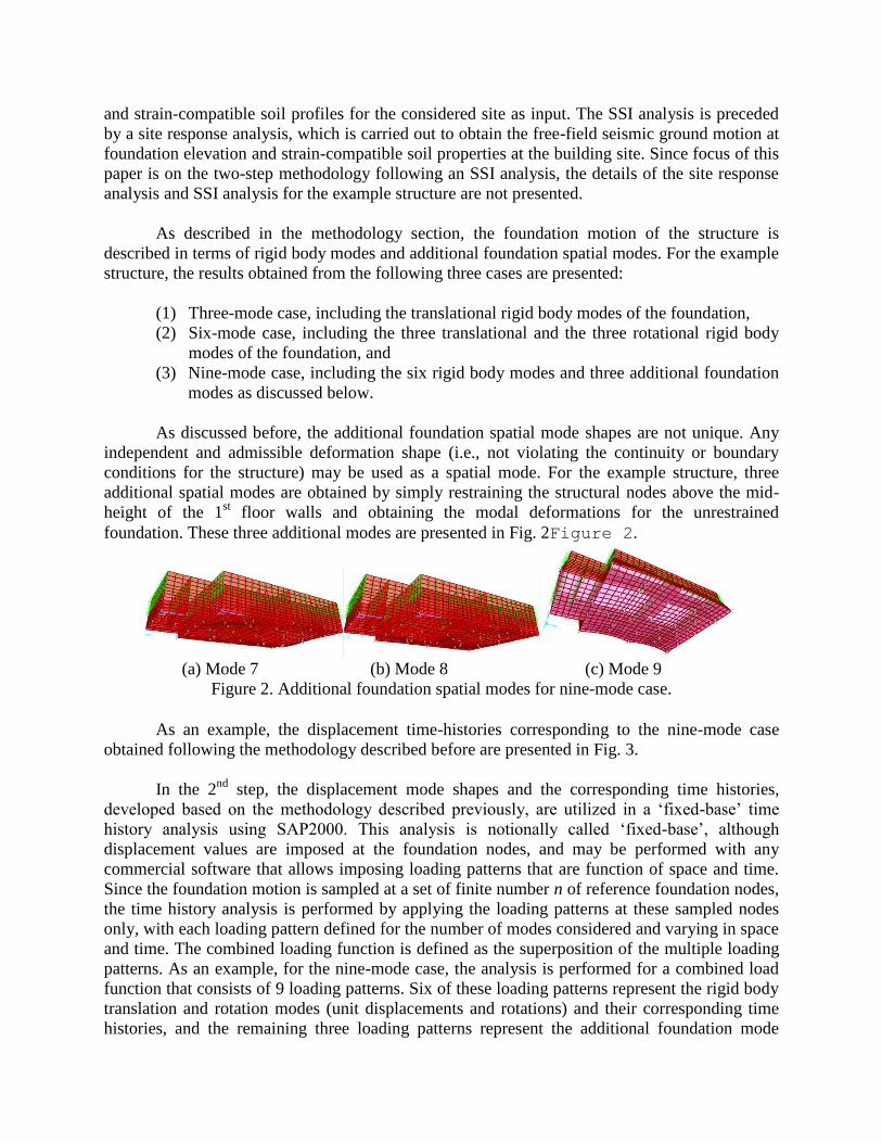
As discussed before, the additional foundation spatial mode shapes are not unique. Any
independent and admissible deformation shape (i.e., not violating the continuity or boundary
conditions for the structure) may be used as a spatial mode. For the example structure, three
additional spatial modes are obtained by simply restraining the structural nodes above the mid-
height of the 1st floor walls and obtaining the modal deformations for the unrestrained
foundation. These three additional modes are presented in Fig. 2Figure 2.
(a) Mode 7 (b) Mode 8 (c) Mode 9
Figure 2. Additional foundation spatial modes for nine-mode case.
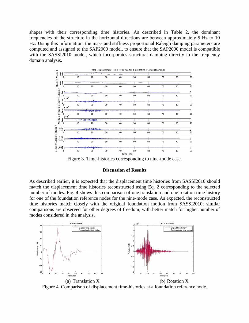
As an example, the displacement time-histories corresponding to the nine-mode case
obtained following the methodology described before are presented in Fig. 3.
In the 2nd
step, the displacement mode shapes and the corresponding time histories,
developed based on the methodology described previously, are utilized in a ‘fixed-base’ time
history analysis using SAP2000. This analysis is notionally called ‘fixed-base’, although
displacement values are imposed at the foundation nodes, and may be performed with any
commercial software that allows imposing loading patterns that are function of space and time.
Since the foundation motion is sampled at a set of finite number n of reference foundation nodes,
the time history analysis is performed by applying the loading patterns at these sampled nodes
only, with each loading pattern defined for the number of modes considered and varying in space
and time. The combined loading function is defined as the superposition of the multiple loading
patterns. As an example, for the nine-mode case, the analysis is performed for a combined load
function that consists of 9 loading patterns. Six of these loading patterns represent the rigid body
translation and rotation modes (unit displacements and rotations) and their corresponding time
histories, and the remaining three loading patterns represent the additional foundation mode
shapes with their corresponding time histories. As described in Table 2, the dominant
frequencies of the structure in the horizontal directions are between approximately 5 Hz to 10
Hz. Using this information, the mass and stiffness proportional Raleigh damping parameters are
computed and assigned to the SAP2000 model, to ensure that the SAP2000 model is compatible
with the SASSI2010 model, which incorporates structural damping directly in the frequency
domain analysis.
Figure 3. Time-histories corresponding to nine-mode case.
Discussion of Results
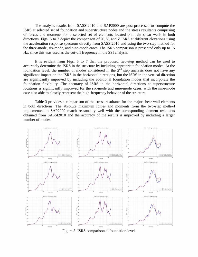
As described earlier, it is expected that the displacement time histories from SASSI2010 should
match the displacement time histories reconstructed using Eq. 2 corresponding to the selected
number of modes. Fig. 4 shows this comparison of one translation and one rotation time history
for one of the foundation reference nodes for the nine-mode case. As expected, the reconstructed
time histories match closely with the original foundation motion from SASSI2010; similar
comparisons are observed for other degrees of freedom, with better match for higher number of
modes considered in the analysis.
(a) Translation X
(b) Rotation X
Figure 4. Comparison of displacement time-histories at a foundation reference node.
The analysis results from SASSI2010 and SAP2000 are post-processed to compute the
ISRS at selected set of foundation and superstructure nodes and the stress resultants comprising
of forces and moments for a selected set of elements located on main shear walls in both
directions. Figs. 5 to 7 depict the comparison of X, Y, and Z ISRS at different elevations using
the acceleration response spectrum directly from SASSI2010 and using the two-step method for
the three-mode, six-mode, and nine-mode cases. The ISRS comparison is presented only up to 15
Hz, since this was used as the cut-off frequency in the SSI analysis.
It is evident from Figs. 5 to 7 that the proposed two-step method can be used to
accurately determine the ISRS in the structure by including appropriate foundation modes. At the
foundation level, the number of modes considered in the 2nd
step analysis does not have any
significant impact on the ISRS in the horizontal directions, but the ISRS in the vertical direction
are significantly improved by including the additional foundation modes that incorporate the
foundation flexibility. The accuracy of ISRS in the horizontal directions at superstructure
locations is significantly improved for the six-mode and nine-mode cases, with the nine-mode
case also able to closely represent the high-frequency behavior of the structure.
Table 3 provides a comparison of the stress resultants for the major shear wall elements
in both directions. The absolute maximum forces and moments from the two-step method
implemented in SAP2000 match reasonably well with the corresponding element resultants
obtained from SASSI2010 and the accuracy of the results is improved by including a larger
number of modes.
Figure 5. ISRS comparison at foundation level.
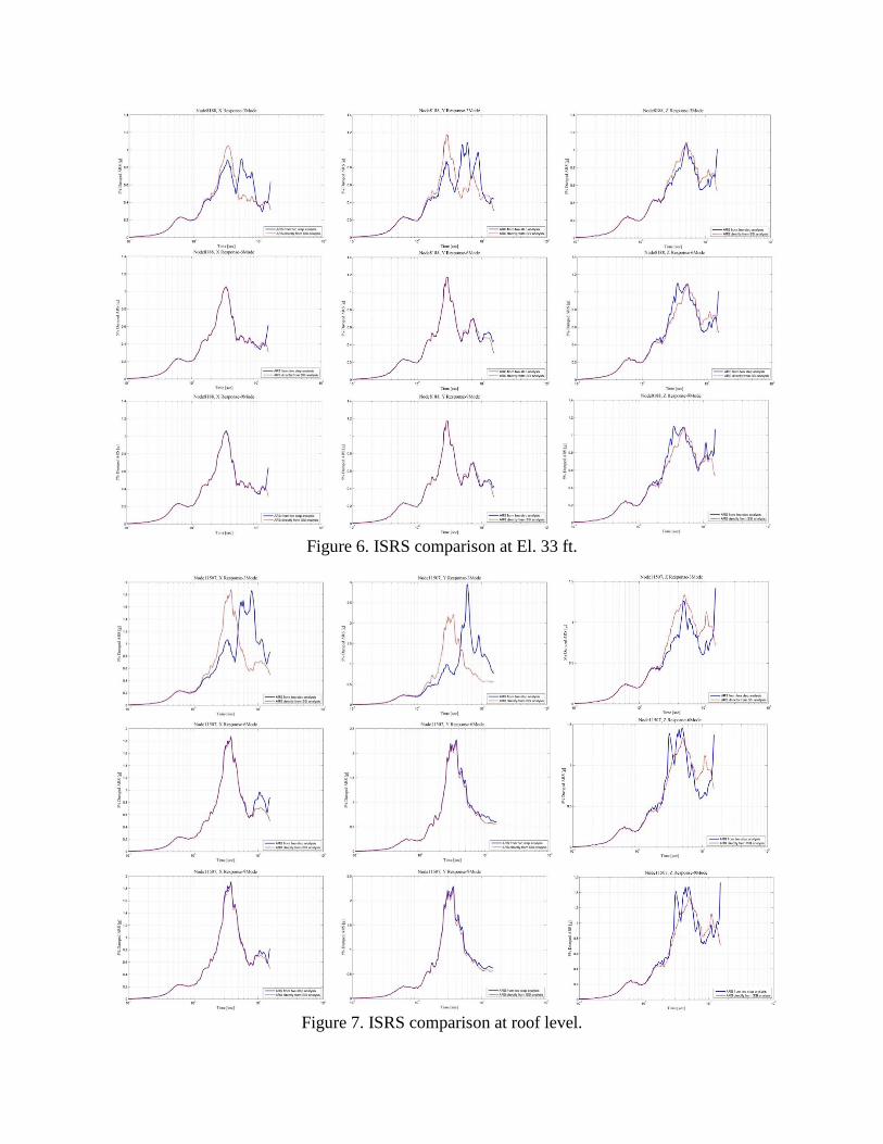
Figure 6. ISRS comparison at El. 33 ft.
Figure 7. ISRS comparison at roof level.
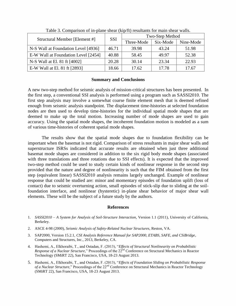
Table 3. Comparison of in-plane shear (kip/ft) resultants for main shear walls.
Structural Member [Element #] SSI Two-Step Method
Three-Mode Six-Mode Nine-Mode
N-S Wall at Foundation Level [4936] 46.71 39.98 43.24 51.98
E-W Wall at Foundation Level [2454] 40.88 58.45 49.97 52.38
N-S Wall at El. 81 ft [4002] 20.28 30.14 23.34 22.93
E-W Wall at El. 81 ft [2893] 18.66 17.62 17.78 17.67
Summary and Conclusions
A new two-step method for seismic analysis of mission-critical structures has been presented. In
the first step, a conventional SSI analysis is performed using a program such as SASSI2010. The
first step analysis may involve a somewhat coarse finite element mesh that is deemed refined
enough from seismic analysis standpoint. The displacement time-histories at selected foundation
nodes are then used to develop time-histories for the individual spatial mode shapes that are
deemed to make up the total motion. Increasing number of mode shapes are used to gain
accuracy. Using the spatial mode shapes, the incoherent foundation motion is modeled as a sum
of various time-histories of coherent spatial mode shapes.
The results show that the spatial mode shapes due to foundation flexibility can be
important when the basemat is not rigid. Comparison of stress resultants in major shear walls and
superstructure ISRSs indicated that accurate results are obtained when just three additional
basemat mode shapes are considered in addition to the six rigid body mode shapes (associated
with three translations and three rotations due to SSI effects). It is expected that the improved
two-step method could be used to study certain kinds of nonlinear response in the second step
provided that the nature and degree of nonlinearity is such that the FIM obtained from the first
step (equivalent linear) SASSI2010 analysis remains largely unchanged. Example of nonlinear
response that could be studied are: minor and momentary episodes of foundation uplift (loss of
contact) due to seismic overturning action, small episodes of stick-slip due to sliding at the soil-
foundation interface, and nonlinear (hysteretic) in-plane shear behavior of major shear wall
elements. These will be the subject of a future study by the authors.
References
1. SASSI2010 – A System for Analysis of Soil-Structure Interaction, Version 1.1 (2011), University of California,
Berkeley.
2. ASCE 4-98 (2000), Seismic Analysis of Safety-Related Nuclear Structures, Reston, VA.
3. SAP2000, Version 15.2.1, CSI Analysis Reference Manual for SAP2000, ETABS, SAFE, and CSiBridge,
Computers and Structures, Inc., 2013, Berkeley, CA.
4. Hashemi, A., Elkhoraibi, T., and Ostadan, F. (2013), “Effects of Structural Nonlinearity on Probabilistic
Response of a Nuclear Structure,” Proceedings of the 22nd
Conference on Structural Mechanics in Reactor
Technology (SMiRT 22), San Francisco, USA, 18-23 August 2013.
5. Hashemi, A., Elkhoraibi, T., and Ostadan, F. (2013), “Effects of Foundation Sliding on Probabilistic Response
of a Nuclear Structure,” Proceedings of the 22nd
Conference on Structural Mechanics in Reactor Technology
(SMiRT 22), San Francisco, USA, 18-23 August 2013.