improved tool development process for novel scs technology for
TRANSCRIPT

7th European LS-DYNA Conference
© 2009 Copyright by DYNAmore GmbH
Improved Tool development Process for novel SCS Technology for Aluminium Sheet Metal
Apostolos Papaioanu(1), Ralf Schleich(2), Prof. Dr. Mathias Liewald MBA(1)
(1) Institut für Umformtechnik, Holzgartenstr. 17, 70174 Stuttgart, Germany (2) HochschulInstitute Neckarsulm, Gottlieb-Daimler-Str. 40, 74172 Neckarsulm, Germany
Summary Today’s stretch forming technologies mainly are used for production of large and flat parts made of sheet metal mainly for the aircraft industry (wing fabrication) and for shipbuilding. Because of the high investment costs and high process time, the use of such conventional stretch forming technologies is not qualified for production of car body panels. However, benefits of present stretch forming methods such as improvement of the mechanical properties of these parts today makes stretch forming technologies attractive for automotive industry. For this very reason a new technology for stretch forming of sheet metals (Short-Cycle-Stretch forming SCS) has been developed at the Institute for Metal Forming Technology (IFU) at Universitaet Stuttgart [1]. The SCS technology combines a plane pre-stretching and subsequent deep drawing operation for production of small car body panels with high demands concerning surface quality. SCS technology is based on a low cost tool which is used in a single action deep drawing press with short process cycles [2]. Former investigations have shown the tremendous potentials of the SCS technology by using typical mild steel alloys for car body panels. Conducted investigations about theoretical achievable effective strain in the stretched region included experimental validation which approved an effective strain value of φ≈0.09 in the stretched region of the specimen [3]. In order to fulfil increasing environmental regulations, the automotive industry focuses on reducing car body’s weight by using lightweight materials such as aluminium or high strength steel. SCS technology offers the possibility of producing car body panels with high surface quality at a minimum of investment costs. Therefore it is necessary to verify SCS technology for new lightweight sheet metal materials as described in [3]. Because of the material properties of high strength steel it does not make sense to investigate such materials for their use with SCS technology regarding the denting resistance and the part stiffness. However, aluminium is due to lower material properties predestinated for a pre-stretching process to increase such properties. The SCS technology offers a huge potential for pre-stretching aluminium blanks and to produce parts with significant better part quality with regard to part stiffness and dent resistance. Keywords: SCS Technology, Stretch Forming, Sheet Metal Forming of Aluminium, Forming Simulation
7th European LS-DYNA Conference
© 2009 Copyright by DYNAmore GmbH
1 Introduction Car body panels are frequently exposed to external mechanical loads by hailstorm or stone impact. These local loadings often result in local severe plastic deformation. Numerous investigations have shown, that pre-stretching of sheet metal parts increases the denting resistance of the parts [3]. Conventional stretch forming technologies allow for the production of parts with increased denting resistance due to pre-stretching. Utilizing such stretch forming technologies mainly large and flat parts for the aircraft industry and for shipbuilding can be produced. Because of the high investment costs and high process time the use of such conventional stretch forming technologies is not qualified for the production of car body panels. In order to benefit from stretch forming technologies but also to save investment costs, the newly developed SCS technology appears to be predestinated for the stretch forming technology becoming again attractive for automotive industry. The SCS technology combines short process cycles and optimal part quality [3].
2 Short-Cycle-Stretch forming (SCS) In this chapter the basic function of the SCS technology and former investigations on SCS are explained.
2.1 Basic function
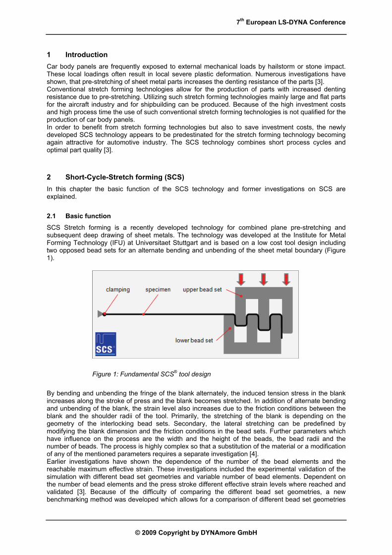
SCS Stretch forming is a recently developed technology for combined plane pre-stretching and subsequent deep drawing of sheet metals. The technology was developed at the Institute for Metal Forming Technology (IFU) at Universitaet Stuttgart and is based on a low cost tool design including two opposed bead sets for an alternate bending and unbending of the sheet metal boundary (Figure 1).
Figure 1: Fundamental SCS® tool design
By bending and unbending the fringe of the blank alternately, the induced tension stress in the blank increases along the stroke of press and the blank becomes stretched. In addition of alternate bending and unbending of the blank, the strain level also increases due to the friction conditions between the blank and the shoulder radii of the tool. Primarily, the stretching of the blank is depending on the geometry of the interlocking bead sets. Secondary, the lateral stretching can be predefined by modifying the blank dimension and the friction conditions in the bead sets. Further parameters which have influence on the process are the width and the height of the beads, the bead radii and the number of beads. The process is highly complex so that a substitution of the material or a modification of any of the mentioned parameters requires a separate investigation [4]. Earlier investigations have shown the dependence of the number of the bead elements and the reachable maximum effective strain. These investigations included the experimental validation of the simulation with different bead set geometries and variable number of bead elements. Dependent on the number of bead elements and the press stroke different effective strain levels where reached and validated [3]. Because of the difficulty of comparing the different bead set geometries, a new benchmarking method was developed which allows for a comparison of different bead set geometries
7th European LS-DYNA Conference
© 2009 Copyright by DYNAmore GmbH
by considering the number of bead elements, the height of the beads and the reached effective strain level [2, 4, 5]. Depending on the bead set geometry and the blank strip dimensions a maximum effective strain of φ≈0.09 was realised.
2.2 Close-to-production tool concept
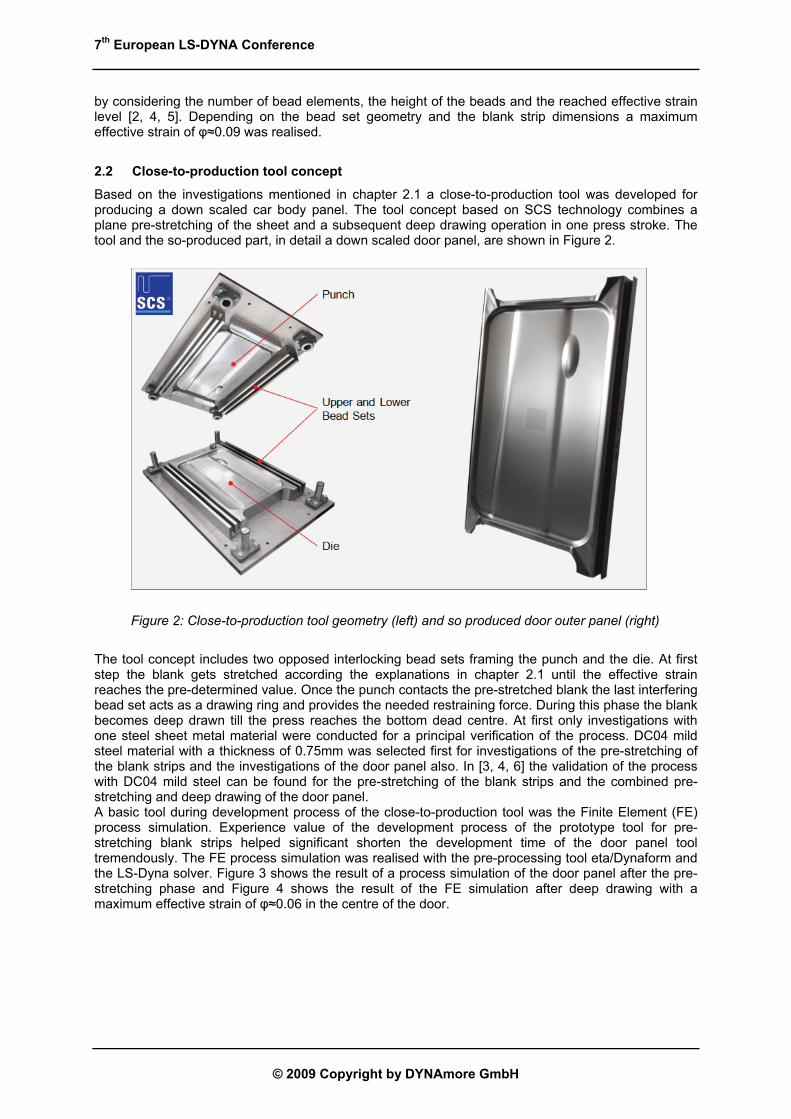
Based on the investigations mentioned in chapter 2.1 a close-to-production tool was developed for producing a down scaled car body panel. The tool concept based on SCS technology combines a plane pre-stretching of the sheet and a subsequent deep drawing operation in one press stroke. The tool and the so-produced part, in detail a down scaled door panel, are shown in Figure 2.
Figure 2: Close-to-production tool geometry (left) and so produced door outer panel (right)
The tool concept includes two opposed interlocking bead sets framing the punch and the die. At first step the blank gets stretched according the explanations in chapter 2.1 until the effective strain reaches the pre-determined value. Once the punch contacts the pre-stretched blank the last interfering bead set acts as a drawing ring and provides the needed restraining force. During this phase the blank becomes deep drawn till the press reaches the bottom dead centre. At first only investigations with one steel sheet metal material were conducted for a principal verification of the process. DC04 mild steel material with a thickness of 0.75mm was selected first for investigations of the pre-stretching of the blank strips and the investigations of the door panel also. In [3, 4, 6] the validation of the process with DC04 mild steel can be found for the pre-stretching of the blank strips and the combined pre-stretching and deep drawing of the door panel. A basic tool during development process of the close-to-production tool was the Finite Element (FE) process simulation. Experience value of the development process of the prototype tool for pre-stretching blank strips helped significant shorten the development time of the door panel tool tremendously. The FE process simulation was realised with the pre-processing tool eta/Dynaform and the LS-Dyna solver. Figure 3 shows the result of a process simulation of the door panel after the pre-stretching phase and Figure 4 shows the result of the FE simulation after deep drawing with a maximum effective strain of φ≈0.06 in the centre of the door.

7th European LS-DYNA Conference
© 2009 Copyright by DYNAmore GmbH
Figure 3: Forming simulation result of the door panel after pre-stretching [3]
Figure 4: Forming simulation result of the door panel after deep drawing [3]
2.3 Further realised investigations on SCS
Further investigations concerning SCS technology dealt with variation of bead set configuration around the blank. For example a pre-stretching of a triangular blank was simulated with a bead set design including three bead sets positioned at all three blank borders. Such trials were also realised for circular and trapezoidal blanks with analogue bead set design [7]. Investigations about the dependence of simulative parameters such as mesh refinement and stroke velocity were analysed also. Further information on this topic can be found in [8]. Feasibility of a door panel with an AA6016 aluminium alloy was also proofed simulative [8]. The simulation was a first attempt, so that no adjustment of the bead set geometry due to material modification was realised. However, the results were convincing so the application of SCS technology with use of aluminium alloys appears feasible.
3 Tool development process for SCS technology for aluminium alloys In order to enhance the bead set geometry for pre-stretching aluminium alloys a strategy for the development process was chosen to accomplish this aim effectively. The several steps of development process are described in this chapter.
3.1 Theoretical basics for bead set geometry optimisation
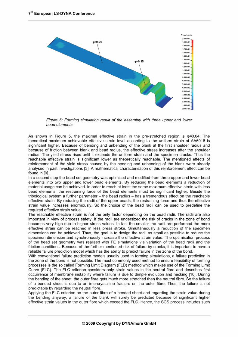
As in [5] described, it is possible to pre-stretch DC04 mild steel with two different bead set geometries to same effective strain level. First geometry features three upper and three lower bead elements and the second offers two upper and two lower bead elements. Following the objective of using minimal blank, a bead set geometry for aluminium alloys with two upper and two lower bead sets was realised, too. At first, bead set geometries with three upper and three lower beads were designed and simulated with the aim of identifying the maximum reachable effective strain with aluminium. The simulation result of the most effective geometry with three upper and three lower bead sets is shown in Figure 5.
7th European LS-DYNA Conference
© 2009 Copyright by DYNAmore GmbH
Figure 5: Forming simulation result of the assembly with three upper and lower bead elements
As shown in Figure 5, the maximal effective strain in the pre-stretched region is φ≈0.04. The theoretical maximum achievable effective strain level according to the uniform strain of AA6016 is significant higher. Because of bending and unbending of the blank at the first shoulder radius and because of friction between blank and bead radius, the effective stress increases after the shoulder radius. The yield stress rises until it exceeds the uniform strain and the specimen cracks. Thus the reachable effective strain is significant lower as theoretically reachable. The mentioned effects of reinforcement of the yield stress caused by the bending and unbending of the blank were already analysed in past investigations [3]. A mathematical characterisation of this reinforcement effect can be found in [9]. In a second step the bead set geometry was optimised and modified from three upper and lower bead elements into two upper and lower bead elements. By reducing the bead elements a reduction of material usage can be achieved. In order to reach at least the same maximum effective strain with less bead elements, the restraining force of the bead elements must be significant higher. Beside the tribological system a further parameter – the bead radius – has a tremendous effect on the reachable effective strain. By reducing the radii of the upper beads, the restraining force and thus the effective strain value increases enormously. So the choice of the bead radii can be used to predefine the required effective strain value. The reachable effective strain is not the only factor depending on the bead radii. The radii are also important in view of process safety. If the radii are undersized the risk of cracks in the zone of bond becomes very high due to higher stress values. In fact the smaller the radii are performed the more effective strain can be reached in less press stroke. Simultaneously a reduction of the specimen dimensions can be achieved. Thus, the goal is to design the radii as small as possible to reduce the specimen dimension and synchronously increase the effective strain value. The optimisation process of the bead set geometry was realised with FE simulations via variation of the bead radii and the friction conditions. Because of the further mentioned risk of failure by cracks, it is important to have a reliable failure prediction model which has the ability to predict failure in the zone of the bond. With conventional failure prediction models usually used in forming simulations, a failure prediction in the zone of the bond is not possible. The most commonly used method to ensure feasibility of forming processes is the so called Forming Limit Diagram (FLD) method which makes use of the Forming Limit Curve (FLC). The FLC criterion considers only strain values in the neutral fibre and describes first occurrence of membrane instability where failure is due to dimple evolution and necking [10]. During the bending of the sheet, the outer fibre gets much more stretched then the neutral fibre. So the failure of a bended sheet is due to an intercrystalline fracture on the outer fibre. Thus, the failure is not predictable by regarding the neutral fibre. Applying the FLC criterion on the outer fibre of a bended sheet and regarding the strain value during the bending anyway, a failure of the blank will surely be predicted because of significant higher effective strain values in the outer fibre which exceed the FLC. Hence, the SCS process includes such

7th European LS-DYNA Conference
© 2009 Copyright by DYNAmore GmbH
bending operations of the sheet metal, the FLC criterion gives no predictable statement of feasibility. In order to detect the failure of a bended sheet also and thus develop an effective bead set geometry, an enhanced failure prediction model which considers materials bendability was used. The enhanced failure model considers strain distribution of the outer fibre and the neutral fibre of the sheet metal. So it is possible to predict the feasibility of a mainly bending stressed part. In [11, 12] the so called Bending Limit Curve (BLC) was already described which considers failure under bending dominated loads. In this case a combined loading of bending and stretching is predominant so the BLC criterion itself is not useful for failure prediction. Investigations have shown that a combined load of stretching and simultaneous bending, like in SCS process realised, increases material’s bendability to strain values exceeding the FLC. In order to predict feasibility of bended dominated processes with high stretch value the further mentioned enhanced failure prediction model was used. The so called cFLC model according to [10] considers the strain value in the outer fibre in relation to the strain value in the neutral fibre and the bending radius. Thus the cFLC model is able to predict a failure during SCS process and helps improving the bead set geometry to an optimum.
3.2 Simulative optimisation of bead set geometry
Considering the mentioned parameters the bead set geometry was enhanced with variation of the bead radii, the bead height, the drawing clearance and the specimen dimension. The designed tool concepts with different bead set geometries were simulated to predict the reachable effective strain and to predict feasibility of the part using the enhanced failure model (cFLC). Over forty bead set geometries were designed and simulated. In Figure 6 the base model of the bead set geometry and the varied parameters during development process are shown on the top. The diagram shows the development process with increasing reachable effective strain during development process. Finally, under regard of realising a high effective strain value, the bead set geometry number forty was chosen and produced.
Figure 6: Bead set geometry under regard of varied parameters and results of development process
The used failure prediction model helped essentially finding the optimal bead set geometry. Regarding the reached effective strain in the interested pre-stretched area of e.g. geometry number twenty-seven and geometry number forty, there is a great difference. Although the reached effective strain by geometry number twenty-seven is just φ≈0.02 (see Figure 6) the specimen has cracked during bending. The specimen realised with geometry number forty reaches φ≈0.04 (see Figure 6) and is safe. The cracking of the specimen number twenty-seven is due to enormous higher strain value in the outer fibre in the zone of the bond. Regarding Figure 7, the strain of the neutral fibre is φ≈0.16 and the

7th European LS-DYNA Conference
© 2009 Copyright by DYNAmore GmbH
FLC criterion predicts a safe part. The outer fibre shows simultaneously a strain value of φ≈0.49. The cFLC is significant higher of the cFLC of specimen forty due to closer bead radius. Thus, the strain is so high that the specimen cracks in the zone of bond due to an intercrystalline fracture. In Figure 8 the strain level of the neutral fibre of specimen number forty in the zone of the bond is infinitesimal lower and reaches φ≈0.11. In regard to the FLC criterion the process is safe. The cFLC is lower of the cFLC of specimen twenty-seven but the strain level in the outer fibre is only φ≈0.26 and consequently safe.
Figure 7: FLC and cFLC of the bended probe with r=1mm
Figure 8: FLC and cFLC of the bended probe with r=4mm
Looking closer to the geometry number forty and the process simulation under regard of the further mentioned reinforcement effect after the shoulder radius, the process limit of this bead set geometry can be predicted. In Figure 9 the flow curve of the used AC170PX aluminium alloy and the mentioned reinforcement effect after the first bead radius are shown. With regard to the materials yield stress, the reached effective strain of φ≈0.04 is nearby the maximum possible.
Figure 9: Flow curve of AC170PX and forming simulation result of the pre-stretched specimen
The enhancement process of the bead set geometry for pre-stretching aluminium alloys can be distinguished in several steps. In the first instance FE simulations with the initial bead set geometry including three upper and three lower bead sets were realised for identifying the maximum achievable
7th European LS-DYNA Conference
© 2009 Copyright by DYNAmore GmbH
strain level. Next the geometry was modified from three into two lower and two upper bead sets to reduce material usage. The geometry was optimised stepwise for achieving a maximum effective strain under regard of possible failure. Therefore the enhanced failure prediction model was applied to ensure feasibility.
3.3 Experimental research and evaluation of process simulation
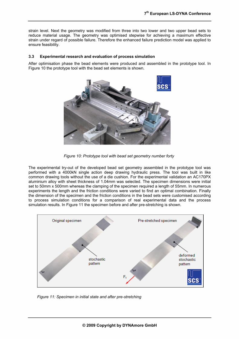
After optimisation phase the bead elements were produced and assembled in the prototype tool. In Figure 10 the prototype tool with the bead set elements is shown.
Figure 10: Prototype tool with bead set geometry number forty
The experimental try-out of the developed bead set geometry assembled in the prototype tool was performed with a 4000kN single action deep drawing hydraulic press. The tool was built in like common drawing tools without the use of a die cushion. For the experimental validation an AC170PX aluminium alloy with sheet thickness of 1.04mm was selected. The specimen dimensions were initial set to 50mm x 500mm whereas the clamping of the specimen required a length of 55mm. In numerous experiments the length and the friction conditions were varied to find an optimal combination. Finally the dimension of the specimen and the friction conditions in the bead sets were customised according to process simulation conditions for a comparison of real experimental data and the process simulation results. In Figure 11 the specimen before and after pre-stretching is shown.
Figure 11: Specimen in initial state and after pre-stretching

7th European LS-DYNA Conference
© 2009 Copyright by DYNAmore GmbH
In order to compare the process simulation results with the gained experimental data the GOM-ARAMIS system for optical 3D deformation analysis was used. It is ideally suited to measure three-dimensional deformation and strain in real components and material specimens, with high temporal and local resolution as well as with a high accuracy. Therefore a stochastic pattern was applied onto the specimen's surface (see Figure 11). Individual images of the pattern were recorded before the pre-stretching of the specimen using CCD cameras. Afterwards the 3D coordinates, the 3D displacements and the plane strain tensor were calculated automatically using photogrammetric evaluation procedures. In Figure 12 the measured strain levels in three different areas of the specimen is shown. The middle section of the specimen in the upper picture area shows the effective strain level which is relevant for a subsequent deep drawing process. Experimental results show a strain level of φ1≈0.04 and a thickness reduction of the blank to a value of s1≈1.016mm. Further interesting areas are the zone after the shoulder radius for a failure prediction due to membrane instability and the outer fibre strain level of the radius marked in the lower picture area for a failure prediction due to combined bending and stretching. In the zone after first shoulder radius an effective strain of φ1≈0.16 was measured. In the lower picture area a strain level of φ1≈0.25 in the outer fibre was measured. As already in chapter 3.2 described, the process is due to higher cFLC safe (see Figure 8). Looking closer to Figure 12 it is visible that the specimen was digitised after experiment. The specimen was digitised with GOM-ATOS. The GOM-ATOS system is a flexible optical measuring machine and is based on the principle of triangulation. The system generates 3D coordinates with help of two cameras and creates a three-dimensional model of the probe.
Figure 12: Analysis of the experimental data Figure 13: Analysis of the process simulation
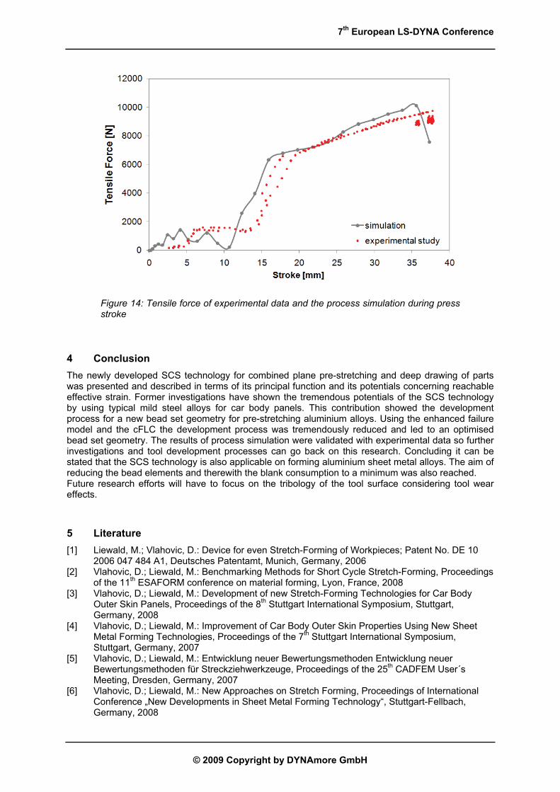
The results of the experiment were compared with the simulative gained results which are shown in Figure 13. The FE simulation results nearly agree with the experimental data. In the free stretched region also a strain level of φ1≈0.04 was computed. The two areas after the shoulder radius and the marked radius also agree with the experimental values of φ1≈0.16 and φ1≈0.26. Beside the comparison of the effective strain between the experimental data and the process simulation results, the validation also included a comparison of the sheet thinning and the edge entry (see Figure 12). The thickness of the specimen was after the pre-stretching s1≈1.016mm while the thickness prediction of the FE simulation was nearby s1≈1.011mm. The comparison of the edge entry of the experiment and of the FE simulation showed a discrepancy. In the experiment the edge length was about e≈9.8mm while the FE simulation predicted a length of e≈6.3mm. The reason of this discontinuity could not be identified. Finally the tensile force during press stroke was regarded and compared with the FE simulation. The force was recorded with a force sensor during press stroke and afterwards analysed. The data of the FE simulation allow for a comparison of the tensile force by converting the computed stress during press stroke into tensile force with use of the blanks cross sectional area. In Figure 14 the tensile force of the experiment and of the process simulation is shown. In summary the results of the experiment are in a good agreement with the results of the conducted FE process simulation.
7th European LS-DYNA Conference
© 2009 Copyright by DYNAmore GmbH
Figure 14: Tensile force of experimental data and the process simulation during press stroke
4 Conclusion The newly developed SCS technology for combined plane pre-stretching and deep drawing of parts was presented and described in terms of its principal function and its potentials concerning reachable effective strain. Former investigations have shown the tremendous potentials of the SCS technology by using typical mild steel alloys for car body panels. This contribution showed the development process for a new bead set geometry for pre-stretching aluminium alloys. Using the enhanced failure model and the cFLC the development process was tremendously reduced and led to an optimised bead set geometry. The results of process simulation were validated with experimental data so further investigations and tool development processes can go back on this research. Concluding it can be stated that the SCS technology is also applicable on forming aluminium sheet metal alloys. The aim of reducing the bead elements and therewith the blank consumption to a minimum was also reached. Future research efforts will have to focus on the tribology of the tool surface considering tool wear effects.
5 Literature [1] Liewald, M.; Vlahovic, D.: Device for even Stretch-Forming of Workpieces; Patent No. DE 10
2006 047 484 A1, Deutsches Patentamt, Munich, Germany, 2006 [2] Vlahovic, D.; Liewald, M.: Benchmarking Methods for Short Cycle Stretch-Forming, Proceedings
of the 11th ESAFORM conference on material forming, Lyon, France, 2008 [3] Vlahovic, D.; Liewald, M.: Development of new Stretch-Forming Technologies for Car Body
Outer Skin Panels, Proceedings of the 8th Stuttgart International Symposium, Stuttgart, Germany, 2008
[4] Vlahovic, D.; Liewald, M.: Improvement of Car Body Outer Skin Properties Using New Sheet Metal Forming Technologies, Proceedings of the 7th Stuttgart International Symposium, Stuttgart, Germany, 2007
[5] Vlahovic, D.; Liewald, M.: Entwicklung neuer Bewertungsmethoden Entwicklung neuer Bewertungsmethoden für Streckziehwerkzeuge, Proceedings of the 25th CADFEM User´s Meeting, Dresden, Germany, 2007
[6] Vlahovic, D.; Liewald, M.: New Approaches on Stretch Forming, Proceedings of International Conference „New Developments in Sheet Metal Forming Technology“, Stuttgart-Fellbach, Germany, 2008

7th European LS-DYNA Conference
© 2009 Copyright by DYNAmore GmbH
[7] Papaioanu, A.: Examinations on Development Methods for SCS Based Close to Series Metal Forming Tools, Diploma Thesis, Institute for Metal Forming Technology (IFU), Universitaet Stuttgart, 2008
[8] Papaioanu, A.; Vlahovic, D.; Liewald, M.: Weiterentwickelte Simulationsmethoden machen SCS-Verfahren effizienter, MaschinenMarkt MM, Vogel, 2008
[9] Stoughton, T. B.: Model of Drawbead Forces in Sheet Metal Forming, Proceedings of the 15th Biennial IDDRG Congress, 1988
[10] Schleich, R.; Sindel, M.; Liewald, M.: Investigation on the effect of curvature on forming limit prediction for aluminium sheet alloys, International Journal of Material Forming (IJMF), Springer, 2009
[11] Schleich, R.; Sindel, M.; Liewald, M.: Material Characterisation for Aluminium Sheet Forming Processes in Automotive Industry, Proceedings of International Conference “New Developments in Sheet Metal Forming Technology“, Stuttgart-Fellbach, Germany, 2008
[12] Schleich, R.; Held, C.; Sindel, M.; Liewald, M.: Beitrag zur Qualifizierung von Falzprozessen im Automobilbau, UTF-Science, Meisenbach, 2008