improved sensor less vector control for im drives fed by a matrix converter using nonlinear modeling...
TRANSCRIPT

8/14/2019 Improved Sensor Less Vector Control for IM Drives Fed by a Matrix Converter Using Nonlinear Modeling and Distur…
http://slidepdf.com/reader/full/improved-sensor-less-vector-control-for-im-drives-fed-by-a-matrix-converter 1/8
52 IEEE TRANSACTIONS ON ENERGY CONVERSION, VOL. 21, NO. 1, MARCH 2006
Improved Sensorless Vector Control for InductionMotor Drives Fed by a Matrix Converter UsingNonlinear Modeling and Disturbance Observer
Kyo-Beum Lee , Member, IEEE, and Frede Blaabjerg , Fellow, IEEE
Abstract—This paper presents a new sensorless vector controlsystem for high performance induction motor drives fed by a ma-trix converter with nonlinearity compensation and disturbance ob-server. The nonlinear voltage distortion that is caused by commu-tation delay and on-state voltage drop in switching device is cor-rected by a new matrix converter modeling. The lumped distur-bances such as parameter variation and load disturbance of thesystem are estimated by the radial basis function network (RBFN).An adaptive observer is also employed to bring better responses atthe low speed operation. Experimental results are shown to illus-
trate the performance of the proposed system.
Index Terms—Disturbance observer, induction motor, matrixconverter, nonlinearity modeling, sensorless vector control.
NOMENCLATURE
Stator voltage.
Stator current.
Estimated values of stator current.
Estimated values of rotor flux.
Stator and rotor resistance.
Stator and rotor self inductance.
Mutual inductance.Leakage coefficient.
Rotor time constant.
I. INTRODUCTION
THE induction motor drive fed by matrix converter is su-
perior to the conventional inverter because of the lack of
the bulky dc-link capacitors with limited life time, the bi-di-
rectional power flow capability, the sinusoidal input/output cur-
rents, and adjustable input power factor. Furthermore, because
of the high integration capability and the higher reliability of the
semiconductor structures, the matrix converter topology is rec-
ommended for extreme temperatures and critical volume/weightapplications. However, a few of the practical matrix converters
have been applied to induction motor drive system because the
implementation of switch devices in the matrix converter is dif-
ficult and modulation technique and commutation control are
more complicated than the conventional PWM inverter [1]–[7].
In order to realize a high performance control of induction
motordrivesfedbymatrixconverter,amatrixconvertermodelfor
Manuscript received April 7, 2004; revised October 7, 2004. Paper no. TEC-00090-2004.
The authors are with the Institute of Energy Technology, Aalborg University,Aalborg DK-9220, Denmark (e-mail: [email protected]; [email protected]).
Digital Object Identifier 10.1109/TEC.2005.847957
Fig. 1. The topology of a matrix converter drive.
lowspeedoperationandrobustspeedcontrollerusingdisturbance
observer are proposed in this paper. As for the conventional
inverter to drive induction motors, several respective methods
of nonlinearity modeling for low speed operation are found
in the literature [8]–[10]. On the contrary, research results on
nonlinearity modeling schemes for matrix converters are hardly
reported. The nonlinear voltage distortion in the matrix converter
in low speed operation is comprehensively investigated and
these problems are resolved by online compensation using a new
matrix converter modeling. To improve the low-speed operation
performance, an adaptive full-order observer is employed for
the estimation of the stator flux, the rotor speed, and the
stator resistance over the wide speed operation region [11]. In
addition, the lumped disturbances of the induction motor drive
fed by matrix converter are approximated by a radial basis
function network including parameter variations and external
load disturbances [12]. Experimental results are presented to
verify the effectiveness and feasibility of the proposed controlsystem.
II. SENSORLESS VECTOR CONTROL OF INDUCTION MOTOR
DRIVES FED BY MATRIX CONVERTER
A. Control Principles of Matrix Converter
The main circuit of a matrix converter is shown in Fig. 1.
There are the input filter, the bi-directional switches connected
in a three-phase to three-phase matrix and a clamp circuit. The
input filter is a second order low-pass topology, which is
used to reduce the high-frequency ripple from the input current.
The clamp circuit consists of two diode bridges to connect the
0885-8969/$20.00 © 2005 IEEE

8/14/2019 Improved Sensor Less Vector Control for IM Drives Fed by a Matrix Converter Using Nonlinear Modeling and Distur…
http://slidepdf.com/reader/full/improved-sensor-less-vector-control-for-im-drives-fed-by-a-matrix-converter 2/8
LEE AND BLAABJERG: IMPROVED SENSORLESS VECTOR CONTROL FOR INDUCTION MOTOR DRIVES 53
Fig. 2. Generation of the reference voltage vectors using ISVM (a) in therectification stage and (b) in the inversion stage.
input and the output to a clamp capacitor, in order to protect
the switches against possible over-voltages that appear during
transient.
The most general modulation method for matrix converter is
the Indirect Space Vector Modulation (ISVM), which considers
the matrix converter as a two stage transformation converter:
a rectification stage to provide a constant imaginary dc-link voltage per switching period and an inverter stage to produce
the three output voltages.
The input current vector, that corresponds to the rectifica-
tion stage and the output voltage vector, that corresponds
to the inversion stage are the reference vectors(Fig. 2). The indi-
rect space vector modulation uses a combination of the two ad-
jacent vectors and a zero vector to produce the reference vector.
The ratio between the two adjacent vectors duty cycle deter-
mines the magnitude of the reference vector. The duty cycles
of the active switching vectors for the rectification stage,
are calculated with (1) and the duty cycle of the active switching
vectors for the inversion stage, are calculated with (2)
and (1)
and (2)
where and are the rectification and inversion stage mod-
ulation indexes, and are the angles within their respec-
tive sectors of the input current andoutput voltage referencevec-
tors (see Fig. 2).
To obtain a correct balance of the input currents and the output
voltages in the same switching period, the modulation pattern
should produce all combinations of the rectificationand the inversion switching states, resulting in the
following switching pattern: . Therefore,
each sequence duty cycle is a result of the cross products of the
rectification and the inversion stage duty cycles, while the dura-
tion of the zero-vector is completing the switching sequence as
(3)
The duration of each sequence is found by multiplying the
corresponding duty cycle to the switching period.
The proposed control scheme of sensorless vector control for
induction motor drives fed using a matrix converter is shown
in Fig. 3, which consists of an adaptive observer for speed and
rotor flux estimation, nonlinear modeling compensation of ma-
trix converter, and speed controller using radial basis function
network disturbance observer [11], [12].
B. Sensorless Vector Control Using Adaptive Observer
In order to build a high performance speed sensorless vector
control system for induction motors fed by matrix converter, ac-
curate information on the motor speed, and the flux are required.
An adaptive observer that offers good performance in a large
speed range is employed to make a high performance drive. This
makes use of the analytical model and allows the estimation of
both the rotor speed and flux from the motor currents. Its im-
plementation is relatively simple by means of DSP systems and
standard vector control hardware is suf ficient.
(5)

8/14/2019 Improved Sensor Less Vector Control for IM Drives Fed by a Matrix Converter Using Nonlinear Modeling and Distur…
http://slidepdf.com/reader/full/improved-sensor-less-vector-control-for-im-drives-fed-by-a-matrix-converter 3/8
54 IEEE TRANSACTIONS ON ENERGY CONVERSION, VOL. 21, NO. 1, MARCH 2006
Fig. 3. The proposed sensorless vector control for induction motor drives fed by matrix converter.
Equations required to implement the adaptive observer are
described as
(4)
where (5) is shown at the bottom of the previous page, where
.
In an adaptive observer, the stator resistance is estimated as
(6)
The control block diagram of the adaptive observer including
the stator resistance estimation is shown in Fig. 4.
III. NONLINEAR MODELING OF MATRIX CONVERTER
The control structure shown in Fig. 3 is using the measured
power grid voltages and the output currents. The performance
of the system is very dependent on knowledge of output voltage
and therefore the matrix converter has to be modeled. As in
a voltage source converter influence on the commutation and
voltage drop exists [8].
A. Commutation Delay
The switch commutation is an important issue when oper-
ating a matrix converter. When the current has to be commutated
from one switch to another, it must be done in a four-step op-
eration to avoid the circulating currents [1]. This strategy keeps
both transistors turned on the switch while it is conducting. As
the current changes sign, the conducting diode, by nature, turns
off, and the load current will be taken over by the opposite con-
ducting branch.
Fig. 5 shows two subsequent commutations. The output
voltage is shown with the control signals for the four transistorinvolved. In both cases the load current is positive and the input
Fig. 4. Structure of the adaptive observer used in the sensorless control.
voltage, is greater than . The conducting transistors are
denoted by 1c and 2c whereas the non-conducting transistors
are denoted by 1nc and 2nc.
In Commutation 1, before the commutation process is started,
the output voltage equals . When the commutation process is
terminated, the output voltage will be equal to . As ,
the series diode in the positive conducting transistor in switch
1 is reverse biased, and no commutation takes place before the
conducting transistor in switch 2 is turned OFF a delay time
later. This results in a hard switched commutation. In Commuta-
tion 2, the polarity of the commutation voltage is opposite. The
diode in the conducting branch of the ON-coming switch will beforward biased in the second step of the commutation process
and a natural commutation will take place.
When the phase current is positive, the turn-on and
turn-off time error due to commutation delay is calculated from
Fig. 5 as
(7)
where is the rise time of the switching device and is the
fall time of the switching device.
In a similar way, the turn-on and turn-off time error when the
phase current is negative is calculated as
(8)

8/14/2019 Improved Sensor Less Vector Control for IM Drives Fed by a Matrix Converter Using Nonlinear Modeling and Distur…
http://slidepdf.com/reader/full/improved-sensor-less-vector-control-for-im-drives-fed-by-a-matrix-converter 4/8
LEE AND BLAABJERG: IMPROVED SENSORLESS VECTOR CONTROL FOR INDUCTION MOTOR DRIVES 55
Fig. 5. Four-step commutation in a matrix converter.
From (7) and (8), these equations can be summarized as
(9)
(10)
where is the switching period and is the line to lineinput voltage, and .
The voltage error due to commutation delay in each phase can
be transformed to the stationary reference frame by employing
the concept of the field orientation as shown in (11) at the bottom
of the page, where subscript “ ” denotes the variable in the syn-
chronous reference frame and is the electrical rotor position.
B. On-State Switching Device Loss
The voltage drop in the matrix converter can be higher than
that of the conventional inverter, and causes a severe distur-
bance at very low speed because two devices are all the time
conducting. The threshold voltage of the power device has to
be modeled to improve the low speed operation. If the forward
voltage of the power devices can be approximated by a fixed
threshold value, , the voltage drop across the power devices
is generally characterized as
(12)
The resistance of the power device, simplifies a linear re-
lation between the load current and the inverter voltage as shown
in Fig. 6 and therefore it can be added to the value of the stator
resistance. The value of is estimated by (6).
Fig. 6. Simplified forward on-state characteristics of the power device.
Fig. 7. Output voltage in the matrix converter due to voltage drop across the
power devices. (a)i > 0
, (b)i < 0
.
The on-state voltage drop is dependent on the direction of the
phase current. Fig. 7 shows the voltage drop influence on the
output voltage. The voltage drop in each phase can be trans-
formed to the stationary reference as
(13)
where .
IV. DESIGN OF DISTURBANCE OBSERVER USING
RADIAL BASIS FUNCTION NETWORK
The mechanical system of the motor system can be repre-
sented as shown in Fig. 8.
FromFig. 8 using the estimated speed, , instead of the mea-
sured speed, , the following is obtained:
(14)
(11)
8/14/2019 Improved Sensor Less Vector Control for IM Drives Fed by a Matrix Converter Using Nonlinear Modeling and Distur…
http://slidepdf.com/reader/full/improved-sensor-less-vector-control-for-im-drives-fed-by-a-matrix-converter 5/8
56 IEEE TRANSACTIONS ON ENERGY CONVERSION, VOL. 21, NO. 1, MARCH 2006
Fig. 8. Dynamic model of mechanical system.
where
Equation (14) is expressed by nominal values, but in most prac-
tical cases, inherent uncertainties in the induction motor model
exist. Therefore, it is reasonable to assume that lumped uncer-
tainties are presented in (15). From this, the following equation
can be obtained:
(15)where
where are modeling errors of , is control
input, is the unmodeled uncertainties.
In (15), if the uncertainties, , are exactly known, then the per-
fect control input for the closed loop system (15) to be asymp-
totically stable can be computed as
(16)
where , and is design constant.
The next task is to replace the unknown uncertainties, , by
the output of the RBFN and to develop an adaptation law for ad-
justing the parameters of the RBFN and controller for the pur-
pose of forcing the tracking error to be zero under the lumped
uncertainties.
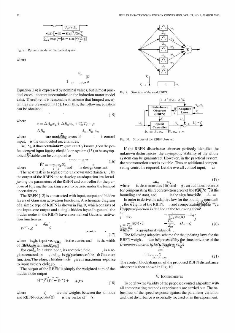
The RBFN [12] is constructed with input, output and hidden
layers of Gaussian activation functions. A schematic diagram
of a simple type of RBFN is shown in Fig. 9, which consists of
one input, one output and a single hidden layer. In general, the
hidden nodes in the RBFN have a normalized Gaussian activa-
tion function as
(17)
where is the input vector, is the center, and is the width
of th Gaussian function.
For each th hidden node, its receptive field, , is a re-
gion centered on , and is the variance of the th Gaussian
function. Therefore, a hidden node gives a maximum response
to input vectors close to .
The output of the RBFN is simply the weighted sum of the
hidden node output
(18)
where are the weights between the th nodeand RBFN output, is the vector of ’s.
Fig. 9. Structure of the used RBFN.
Fig. 10. Structure of the RBFN observer.
If the RBFN disturbance observer perfectly identifies the
unknown disturbances, the asymptotic stability of the whole
system can be guaranteed. However, in the practical system,
the reconstruction error is evitable. Thus an additional compen-
sating control is required. Let the overall control input, as
(19)
where is determined as (16) and is an additional control
for compensating the reconstruction error of the RBFN, , is the
bounding constant, and is the sign function.
In order to derive the adaptive law for the bounding constant,
, the weights of the RBFN, , and compensating input, , a
Lyapunov function is defined in the following form:
(20)
where is an optimal value of .
The following adaptive scheme for the updating laws for the
RBFN weight, can be presented by the time derivative of the
Lyapunov function to be a negative value
(21)
The control block diagram of the proposed RBFN disturbance
observer is then shown in Fig. 10.
V. EXPERIMENTS
To confirm the validity of the proposed control algorithm with
all compensating methods experiments are carried out. The ro-
bustness of the speed response against the parameter variationand load disturbance is especially focused on in the experiment.

8/14/2019 Improved Sensor Less Vector Control for IM Drives Fed by a Matrix Converter Using Nonlinear Modeling and Distur…
http://slidepdf.com/reader/full/improved-sensor-less-vector-control-for-im-drives-fed-by-a-matrix-converter 6/8
LEE AND BLAABJERG: IMPROVED SENSORLESS VECTOR CONTROL FOR INDUCTION MOTOR DRIVES 57
Fig. 11. Forward and reverse operation, experimental results (4 s/div); speedand phase current.
Fig. 12. A zoom of the zero crossing in Fig. 4 (0.4 s/div); speed and phasecurrent.
The experimental setup of the proposed control system consists
of a 3-phase, 380 V, 50 Hz, 4 pole, 3-kW induction motor andpower circuit using matrix converter. A dual controller system
consisting of a 32-bit DSP (ADSP 21 062) and a 16-bit micro-
controller (80C167), in conjunction with a 12-bit A/D converter
board is used to control the matrix converter based induction
motor drive.
Figs. 11 and 12 show experimental results of a sensorless
vector controlled induction motor drive fed by matrix converter.
Fig. 11 shows speed and phase current responses of the proposed
sensorless vector control system in the forward and reverse op-
eration. Fig. 12 shows a zoom of the zero-crossing in the speed
response.
Fig. 13 shows distortion voltages as a function of the rotor
position in the stationary reference frame. Figs. 14–16 show the
experimental results of the current control with a nonlinearity
compensation in the low speed region. The motor is operated at
100 rpm in Figs. 14 and 15, and 5 rpm in Fig. 16. It can be seen
that the current pulsations and their 5th and 7th harmonics are
reduced using the proposed nonlinear modeling, and very good
speed estimation is achieved at the low speed region down to 5
rpm.
Figs. 17 and 18 show the experimental results when the in-
ertia value variation has occurred abrubtly. For speed control
without RBFN disturbance observer, 1 s is taken to overcome
the affection for the tracking error to be zero. However, speed
control with RBFN disturbance observer has a robust character-istic against parameter variation.
Fig. 13. Distortion voltages in the stationary reference frame; q- and d-axisdistortion voltage.
Fig. 14. Experimental results of current control without nonlinearities
compensation at 100 rpm; phase current and harmonic spectrum.
This superiority can also be seen in Figs. 19 and 20. There
is an abrubt load disturbance at 5 s. For the speed control with
RBFN control, it takes about 0.5 s for the tracking error to be
zero, but the speed control without the RBFN observer uses
2 s. From these experimental results, the best speed control
characteristics in the sensorless vector control system are ob-served when the lumped disturbances exist. Especially, the pro-
posed control scheme has robust characteristics against param-
eter variation even though there is a negligible external distur-
bance effect.
VI. CONCLUSION
In order to realize high performance control of induction
motor drives fed by matrix converter, a new matrix converter
modeling for low speed operation and robust speed controller
using a disturbance observer have been proposed in this paper.
The nonlinear voltage distortion that is caused by commu-
tation delay and on state voltage drop in the power deviceis corrected by a simple feed-forward compensation method

8/14/2019 Improved Sensor Less Vector Control for IM Drives Fed by a Matrix Converter Using Nonlinear Modeling and Distur…
http://slidepdf.com/reader/full/improved-sensor-less-vector-control-for-im-drives-fed-by-a-matrix-converter 7/8
58 IEEE TRANSACTIONS ON ENERGY CONVERSION, VOL. 21, NO. 1, MARCH 2006
Fig. 15. Experimental results of current control with nonlinearitiescompensation at 100 rpm; phase current and harmonic spectrum.
Fig. 16. Experimental results of constant speed operation at 5 rpm (1 s/div);speed, and phase current.
Fig. 17. Experimental results of the parameter variation without RBFNdisturbance observer at 500 rpm (1 s/div); speed and phase current.
using the direction of current. In addition, to achieve a robust
control characteristic against unmodeled disturbances such as
parameter variations and load disturbances, the unmodeled
disturbances are approximated by the radial basis functionnetwork. Experimental results show that the proposed control
Fig. 18. Experimental results of the parameter variation with RBFNdisturbance observer at 500 rpm (1 s/div); speed and phase current.
Fig. 19. Experimental results of load disturbance without RBFN disturbance
observer at 500 rpm (1 s/div); speed and phase current.
Fig. 20. Experimental results of load disturbance with RBFN disturbanceobserver at 500 rpm (1 s/div); speed and phase current.
scheme can provide good performance at the low speed region
and robust and stable characteristics against parameter varia-
tions and load disturbance.
REFERENCES
[1] P. Nielsen, F. Blaabjerg, and J. K. Pedersen, “New protection issues of amatrix converter,” IEEE Trans. Ind. Appl., vol. 35, no.5, pp.1150–1161,Sep./Oct. 1999.
8/14/2019 Improved Sensor Less Vector Control for IM Drives Fed by a Matrix Converter Using Nonlinear Modeling and Distur…
http://slidepdf.com/reader/full/improved-sensor-less-vector-control-for-im-drives-fed-by-a-matrix-converter 8/8