improved foundation models for integrated design - … stavanger presentasjoner...improved...
TRANSCRIPT

SMI, Stavanger, 2016-04-06
Kristoffer S. SkauNorwegian Geotechnical Institute
Improved foundation models for integrated design

Houston – 2002
7 persons
Oslo – 1953
220 persons
Trondheim – 2005
20 persons
Kuala Lumpur – 2009
(JV with G & P)
Perth – 2014
7 persons
NGI - Private independent foundation
Established 1953
Consultancy and R&D
National and international clients
Cooperation with universities and research organizations
Key figures
No. of employees = 250
Turnover = around 380 million NOK
6 % from Norwegian Research Council
About 1/3 turnover within Offshore Energy (100 persons)

Soil testing

33
X Y
4 of 31
Instrumentation and measurements

Foundation design

DONG – London Array – 3D FEA with focus on silt layer and effect of sand waves
DONG – Anholt – 3D FEA accounting for cyclic soil behaviour
Statoil – Dudgeon – 3D FEA accounting for cyclic behaviour of glacial till and chalk
Projects

Statoil – HyWind – FEED and complete detailed geotechnical design including cyclic soil behaviour
DONG – Borkum Riffgrund I – FEED and complete detailed geotechnicaldesign including cyclic soil behaviour
DONG – Borkum Riffgrund II – FEED and complete detailed geotechnicaldesign including cyclic soil behaviourand integrated analyses
Projects

REDWIN - Objectives
REDWIN aims at reducing cost in offshore wind by improving the tools used for describing foundation and soil response.
─ The tools should be implemented/integrated in structural programs.
─ The tools should improve important soil issues such as cyclic behaviour, degradation, drainage and damping.

Suction bucket jacket – design processes and
possible loops

Is foundation response important?
Depends on load case and the part of structure we consider
Important for the overall fatigue life
Two examples

Example 1: Jacket on buckets
Variation of FLS
stiffness:
Best Estimate for a site can
deviate from average by a
factor 2 to 3
High- and Low-Estimate
per location 50-200% of
Best Estimate

Example 1: Jacket on buckets
Variation of FLS stiffness:
Soil stiffness Fatigue life
High Estimate 190% 150-250%
Best Estimate 100% 100%
Low Estimate 65% 10-30%

Example 2: Monopile
• Generic OC3 Phase II monopile support structure with NREL 5-MW wind turbine atop
• Distributed Spring model (API p-y curves)
• Fedem Windpower for integrated analysis in time domain
Numerical model:
Schafhirt S, Page A, Eiksund G, Muskulus M (2016)
Influence of Soil Parameters on Fatigue Lifetime for Offshore Wind Turbines with Monopile Support Structure 13th Deep Sea Offshore Wind R&D Conference, EERA DeepWind'2016, 20-22 January 2016,
Trondheim, Norway

Accumulated DEL at mudline normalized to unscaled model:
Soil stiffness (k)
Fatiguedamage
Example 2: Monopile
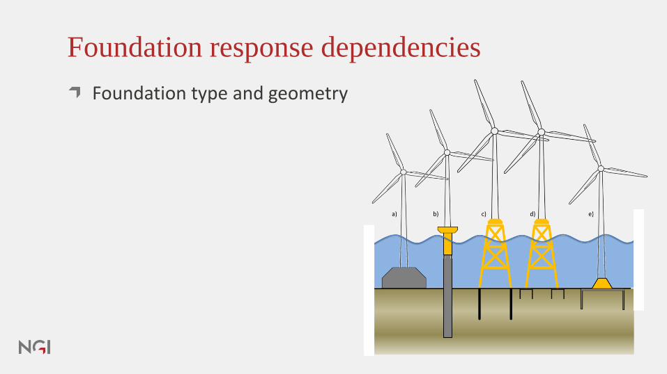
Foundation response dependencies
Foundation type and geometry

Foundation stiffness dependencies
Foundation type and geometry
Stratigraphy/layering

Foundation stiffness dependencies
Foundation type and geometry
Stratigraphy/layering
The soil behaviour within each layer, particularly cyclic behaviour

Foundation stiffness dependencies
Foundation type and geometry
Stratigraphy/layering
The soil behaviour within each layer
Load level

Foundation stiffness dependencies
Foundation type and geometry
Stratigraphy/layering
The soil behaviour within each layer
Load level
Load history

Foundation stiffness dependencies
Foundation type and geometry
Stratigraphy/layering
The soil behaviour within each layer, particularly cyclic behaviour
Load level
Load history
Variability across site and uncertainty

Geotechnical analysis
FE-model include foundation, layers, soil properties onelement level
Soil properties representing a cylic degradation often definedprior to the analyses
Apply relevant loads
F=[V,H,M]

Foundation response in integrated analyses
Soil behaviour
Load level and
history
Soil variability
Foundation type

Nonlinear foundation response
Load
Stif
fnes
s
Displacement
Load

Coupled foundation response
The rotational response depends on the vertical load
Ver
tica
l lo
adMoment load
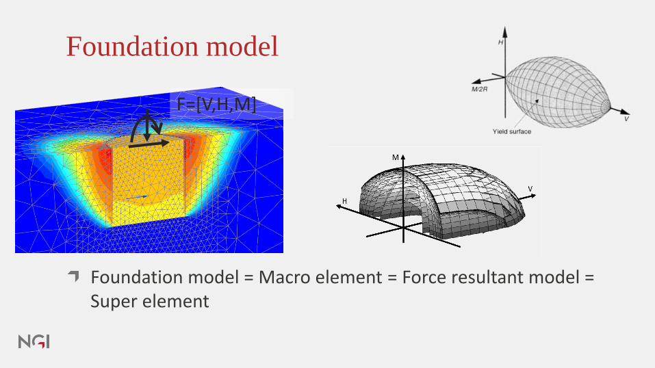
Foundation model
Foundation model = Macro element = Force resultant model = Super element
F=[V,H,M]

The response is determined by both soil and
foundation properties

Expanding series coupled springs to 3D
Multisurface plasticity
Capture stress reversal and coupled response
Produce hystertic damping
Video

Foundation model – theoretical concept
IWAN coupled models
uz
A “plastic” spring gets activated when the slider yields

Video

Model response compared to FEM database
0 0.2 0.4 0.6 0.8 10
0.2
0.4
0.6
0.8
1
H/Hmax
V/V
ma
x
Fcy
/ Fa =0
OCR = 4
N=10
uh =0-0.00475, u
h =0.00025
uv =0.0005-0.01, u
v =0.0005
Foundation model response FE caisson response database

Model response compared to FEM database
Foundation model response FE caisson response database

Macro element / foundation
model
F=[V,H,M]

Improved foundation models
Higher accuracy / more reliable ─ Reducing uncertainty and risk is reducing cost
If simpler model are conservative (they should), the design can be further optimized
Model should be presented with different degrees of sophistication (Difference between concept study and FEED)
The cost reduction potential will be evaluated

Implementation in 3D float

Thank you for your
attention!
Questions and feedback,
please.

@infoNGI
NORGES GEOTEKNISKE INSTITUTTNGI.NO