improved design equations for the result- ant tensile
TRANSCRIPT

Improved Design Equations for the Result-ant Tensile Forces in Glulam Beams with Holes
Cristóbal Tapia Camú, Materials Testing Institute, University of Stuttgart
Simon Aicher, Materials Testing Institute, University of Stuttgart
Keywords: glulam, holes, reinforcement forces, design equations, Eurocode 5, para-metric analysis
1 Introduction The use of holes in beams made of glued laminated beams (glulam) is often neces-sary in constructions, as they are required for the passing-through of plumbing, elec-trical and other service relevant infrastructure systems. These apertures represent a significantly weak region in the beam, leading to noticeable decreases in maximum loading capacities. The failure mechanism is well known and is manifested by the propagation of cracks in the direction of the grain and beam length axis, starting from two zones with high tensile stresses perpendicular to the grain located diagonally op-posite on the periphery of the hole.
The European Timber Design Code, EN 1995-1-1 (2010), hereby EC5, contains no pro-visions for either unreinforced or reinforced holes. The current version of the Ger-man National Annex to EC5 (2013) regulates external hole reinforcements by wood panels (plywood, LVL), as well as the usage of internal, glued-in rods or screws rein-forcements to improve the mechanical response of the glulam/LVL in the region sur-rounding a given aperture. In order to correctly dimension them, design equations are provided to compute the acting forces, which can deviate significatnly from re-sults obtained by means of finite element simulations (Aicher, 2011). This study aims at improved design equations for the tensile forces perpendicular to the grain at the periphery of holes for implementation in the future EC5 version.
Firstly, the paper compares the design forces obtained acc. to EC5/NA (2013) vs. the results of a FE model. Then, a modified set of design equations fitted to the numeri-cal results is presented for holes of different shapes placed symmetrically at mid-

depth. Further, the effect of vertical eccentricities of holes on the design force is in-vestigated. Finally, the presented design equations are assessed with regard to an in-homogeneous build-up.
2 Design of holes in DIN EN 1995-1-1/NA The present design of holes and hole reinforcements according to DIN EN 1995-1-1/NA (2013) is based on a fictive resultant tensile force, Ft,90, representing the inte-gral of the stresses perpendicular to the grain in the hole periphery in the crack rele-vant sections. This force is composed of two additive parts: one, Ft,V, accounting for the shear force, which cannot be transferred in the hole area, and a second part, Ft,M, related to the bending moment present in the cross-section:
𝐹𝑡,90 = 𝐹𝑡,𝑉 + 𝐹𝑡,𝑀 (1)
𝐹𝑡,𝑉 =𝑉 ⋅ ℎ𝑑4 ⋅ ℎ
(3 −ℎ𝑑2
ℎ2) (2)
𝐹𝑡,𝑀 = 0.008 ⋅𝑀
ℎ𝑟. (3)
The shear force part, Ft,V, conforms sensibly to half of the integral of the parabolically distributed shear stresses along the full hole depth (rectangular hole) or 0.7 times of the hole depth for the case of the round holes regarded here (Blaß et al., 2004; Aicher & Höfflin, 2001). The moment related part, Ft,M, is in contrast rather diffuse and needs amendment, as has been discussed previously by Aicher & Höfflin (2001). The dimensional notations of (reinforced) holes according to DIN EN 1995-1-1/NA (2013) are shown in Fig. 1.
The vertical force acc. to Eq. (1) is used for the design of unreinforced and reinforced holes, where it is compared either against a fictive resulting resistance force based on the size-dependent tensile strength of the glulam perpendicular to the grain, or for the design of reinforcement elements (screws, rods, plates).
3 Methodology 3.1 Studied configurations
In this study a variety of holes of different sizes relative to the depth of a rectangular beam cross-section and shapes, all allowed acc. to DIN EN 1995-1-1/NA (2013), were simulated under two different loading situations: one comprising a hole placed in a pure bending moment region, denoted as configuration A (see Fig. 1a), and a second, general case, where the holes are subjected to both shear and moment, here re-ferred to as configuration B (see Fig. 1b). For the latter, different ratios of moment to shear force (M/V) were analyzed at the periphery of the hole; this was achieved by varying the length of the distance lA between 1.5 and 5 times the depth of the beam

h. The relative sizes of the apertures ranged from hd/h = 0.1 to hd/h = 0.4 in incre-ments of 0.05. Regarding the shapes of the holes, round, square and rectangular (side aspect a:hd = 2.5) openings were regarded. For the rectangular shapes a corner radius r = 20 mm was used throughout. In the first major part of the presented inves-tigations the holes were placed at mid-depth of the glulam beam, whilst in the sec-ond part eccentricities were considered, as well.
The eccentricities used in the second part of the study were taken such that each hole would fulfill the current requirements in DIN EN 1995-1-1/NA (2013) where a minimum depth of 0.25h is specified for the reduced cross-sections (hru and hro, see Fig. 1) above and below the hole. For each hole depth, hd, the maximum eccentricity emax was computed and used to create models with ratios e/h ranging from -emax to +emax in steps of 0.05h.
A third part of the study was dedicated to the influence of the inhomogeneity of the build-up, which was studied for a particular, however practically very representative, case of a classified inhomogeneous GL24c build-up given in EN 14080 (2013) with a stiffness ratio Eouter/Einner = 11 000/7 500 = 1.47. Regarding the assessment of the stiff-ness inhomogeneity, exclusively a square hole of depth hd/h = 0.3 and eccentricities of e/h= ± 0.1 were simulated. The ratio lA/h was chosen as 3.
a) b)
c) d)
Figure 1: Hole arrangements (examples), geometry and section forces in the study. a) configuration A; b) configuration B; c) definition of eccentricity and minimum value hro/ru; d) positioning of rectan-gular hole in an inhomogeneous build-up.
3.2 Finite Element Model
A two-dimensional parametric FE-model was programmed in Abaqus V2016 using its python scripting interface. The mesh comprised eight-node, quadratic plain-stress el-

ements with reduced integration (CPS8R) with a side size of approximately 1 mm di-rectly at the perimeter of the hole, increasing up to 5 mm in the region influenced by the hole (≈h away from the perimeter) and reaching about 20 mm at the regions far away from the aperture. Note: the absolute depth of the beam in the FE-analysis, however irrelevant for all below stated results and conclusions, was h = 450 mm.
Under the assumption that the end sections remain plain during deformation, the free nodes at both vertical edges of the beams of configuration A were constrained to move as a rigid body. This was implemented by bonding the nodes at the free ends with two-dimensional rigid elements (R2D2) placed vertically at both ends of the beam, as symbolized by the thick black lines in Fig. 1a. In order to couple the move-ment of the rigid elements and of the associated beam nodes so-called “tight con-straints” were applied. The bending moment was applied at mid-depth of the free ends at both sides.
Similarly, rigid elements were applied to the left end of the configuration B, whilst the nodes of the right end (symmetry condition) were restrained in the horizontal direc-tion. The load P was applied as a line load at the right edge, in order to distribute the shear force along the entire depth.
The linear solver of Abaqus was used, taking care that no geometrical nonlinearities were considered in the computations, which allows for a better comparison with ana-lytical equations that do not account for nonlinear effects.
3.3 Analysis of the obtained results
The analysis of the data focuses mainly on the computation of the forces perpendicu-lar to the grain occurring in the vicinity of the hole. A direct method to do this is de-scribed by Aicher & Höfflin (2001), where the stresses perpendicular to the grain di-rection are integrated along a horizontal path starting from the point of maximum stresses perpendicular to the grain at the perimeter of the hole (ϑ1 and ϑ2) until their values reach zero (see Fig. 2).
Figure 2: Description of the integration path used to compute the vertical force Ft,90

This procedure can be applied at both sides of the hole (I and II) but generally only side II of Fig. 2 is considered, since it leads to the largest values for the computed ver-tical force Ft,90.
The current design approach for holes in the German Annex to EN 1995-1-1 (2013) consists in a decomposition of the total force Ft,90 in two components, attributed to a pure moment and a pure shear force contribution (see Eqs. (1) to (3)). In order to as-sess the accuracy of each one of the terms specified in Eq. (1) to (3) the problem is separated into its two parts, so that they can be analyzed independently. Unfortu-nately, this separation is not trivial, as mechanically trivial pure moment action is pos-sible, however, constant or variable shear force is always associated with superim-posed bending moment action (see Fig. 3).
The methodology used in this study to separate the pure moment and fictive pure shear force effect is based on the approach used by Aicher & Höfflin (2001), where the field of stresses perpendicular to the grain, resulting exclusively from the shear force component, is obtained by subtracting the results of the pure moment configu-ration from the general configuration where shear force and moment are present. This requires both meshes A (pure moment) and B (moment + shear) to perfectly match with each other, in order to allow the computation of the stress difference at each node.
However, the method, as implemented by Aicher & Höfflin (2001), still represents a small inaccuracy, emanating from the fact that the results from the pure bending mo-ment configuration do not account for the variation of the moment along the hole length, ΔM, but uses a constant moment related to the center of the hole. Although the error resulting from this simplification is rather small, this study considers an im-provement to accounts for the variation of the pure bending moment by means of a simple scale factor, individually calculated for the results at each node. In essence, for each node i of the pure bending moment model the obtained stresses are scaled by a factor μi, as shown in Fig. 4.
The factor µi takes into account the magnitude of the moment at each point in the configuration B (shear + moment) and scales the stresses obtained in configuration A (pure moment) accordingly, which can then be subtracted from the results of config-uration B to obtain the influence of a “pure shear-force” loading configuration. The illustrations Fig. 5 show the results of this process for the case of a round hole with
Figure 3: Separation of the regarded bending loading condition into a pure linearly varying moment and a pure constant shear-force component

ratio hd/h = 0.3 and lA/h = 5. Here, Fig. 5a shows a clear distortion of the stresses per-pendicular to the grain due to the moment and shear action. Figs. 5b and c give the
Figure 4: Graphical illustrationof the methodolgy used to scale the stresses perpendicular to the grain at each node of the mesh corresponding to the pure bending moment.
a)
b)
c) d)
Figure 5: Distribution of stresses perpendicular to the grain and beam axis for different real and fictive load configurations. a) real load configuration with shear force and a linearly varying moment; b) real pure bending moment load configuration (moment at hole center); c) fictive pure linearly varying moment load configuration, obtained according to Fig. 4; d) fictive pure shear force loading configuration, obtained by subtracting (c) from (a).

results for constant and linearly varying moment, and Fig. 5d presents the results for the pure shear case. In this way, each component of the vertical force Ft,90 can be in-tegrated independently and later used to compare with the Eqs. (1) to (3) and cali-brate new equations.
4 Results 4.1 Comparison between FE results and current design equations
In the first stage of the analysis the results obtained in the finite element simulations for the vertical force (Ft,90,FE) were compared with the forces Ft,90,eq obtained from ap-plying the NA standard Eqs. (1) to (3). This was done for all simulated configurations, as explained in section 3.1. Figures 6a, 6b and 7a show the ratio Ft,90,FE/Ft,90,eq, for all relevant hole size and shape configurations, revealing how conservative or non-con-servative the standard equations are.
Fig. 6a shows the results for the round holes, where the values denote a rather con-servative force prediction of Eqs. (1) to (3). It can be seen that for larger holes (hd/h) the design equation gets less conservative, and even some values on the unsafe side are obtained for combinations of large holes and low M/V ratio.
It is important to mention that somewhat larger forces are obtained on the “left”, i.e. closer to the support side as compared to the “right” side of the hole configurations (zones 1 and 2 of Fig. 2). Here, values up to 5% higher as the ones obtained with Eqs. (1) to (3) are found. This is mainly due to the fact that the point of maximum stress perpendicular to the grain is found at a larger angle ϑ as compared to the one observed on the side 2, thus, taking a larger portion of the shear stresses of the cross-section. However, since the focus in this study is placed on verifying the accu-racy of Eq. (1), where both terms Ft,M and Ft,V are positive —whilst integration of the pure moment configuration in the zone 1 yields negative values—, a comparison with the vertical force computed at the zone 2 (see Fig. 2) seems more adequate in a first step. Furthermore, this behavior (larger vertical forces on the left side) is only ob-served for round holes, being due to the above described effect.
Fig. 6b shows the results for a quadratic hole, i.e. rectangular hole with a side aspect ratio a:hd = 1:1. Similarly as for round holes, the ratios of FE-computations vs. code-predicted values lay on the conservative side for practically all the studied configura-tions. The most notable difference is the rather smaller variation of the ratios within a same hole size (hd/h ratio), which in the case of round holes is larger.
Finally, Figs. 7a and 7b show the results obtained for the rectangular holes with side aspect ratio a:hd = 2.5:1 (the largest side aspect ratio allowed acc. to DIN EN 1995-1-1/NA (2013)). It can be seen, that the vertical forces calculated from Eqs. (1) to (3) tend to underestimate the FE results, especially for larger holes with low M/V ratio.

Fig. 9b gives further insight into how each of the two components of the total vertical force relate when calculated with either Eqs. (1) to (3) or by FEM, then normalized by the total vertical force Ft,90 computed with the FE model. Values above the line with unitary slope in Fig. 9b mean that the results obtained with the design equations are smaller with respect to the “real” (FE-computed) values, i.e. the design is non-con-servative. On the other hand, values below the line suggest conservative design forces.
It can be observed, that the moment component tends to be conservative or ex-tremely conservative, depending on the size of the hole, while the vertical shear com-
a) b)
Figure 6: Relation of forces Ft,90,FE acc. to finite element analysis vs. the NA results Ft,90,eq (Eqs. (1) to (3)); a) round hole (left side of the hole); b) quadratic hole (right side of the hole)
a) b)
Figure 7: Relation of forces Ft,90,FE acc. to finite element analysis vs. the NA results Ft,90,eq (Eqs. (1) to (3)); a) rectangular hole (right side of the hole); b) Independent analysis of moment and shear components

ponent is predicted in an unsafe manner by Eq. (2). This is why the total force com-puted acc. to Eq. (1) shows non-conservative results for small ratios M/V but con-servative values once the moment component turns more relevant.
4.2 Derivation of improved design equations
4.2.1 Modifications for the shear force component
Regarding the equation related to the computation of the shear force related compo-nent, the approach used is basically the same as the one applied to derive the current design equation (Eq. (1)), with the addition of an extra multiplication term. This yields the relation
𝐹𝑡,𝑉 =𝜉𝑉ℎ𝑑4ℎ
⋅ (3 − (𝜉ℎ𝑑ℎ)2
) ⋅ (1 + 𝛼 (𝜉ℎ𝑑ℎ)), (4)
where V is the shear force present at the analyzed side of the hole, h and hd are depth of the beam and of the hole, respectively. The coefficients α and ξ are factors that need to be fitted to the results from the simulations.
4.2.2 Modifications for the bending moment component
The modification proposed to capture the influence of the bending moment on the total force Ft,90 is based on the solution given by Aicher & Höfflin (2001) for round holes. Hereby the bending stresses are integrated over half of the depth of the hole, since these are the stresses that need to be redirected in the region of the hole (the first two products terms in Eq. (5)). In order to take into account the effects produced by the different geometries, the result of the integration is then multiplied by a third term:
𝐹𝑡,𝑀 =𝜂𝑀
ℎ⋅ (𝜉ℎ𝑑ℎ)2
⋅ (1 + 𝜅𝜉ℎ𝑑ℎ) (5)
In Eq. (5), M, as usual, represents the bending moment at the analyzed side of the hole. The coefficients η and κ factors are determined from fitting to the results from the simulations; whereby coefficient ξ has been obtained within the phase of param-eter determination of Eq. (4).
4.3 Fitting of proposed equations
The fitting process of the coefficients α, ξ, η and κ for the proposed design equations was performed in two consecutive steps for each one of the three different hole ge-ometries studied. For this, the least-squares algorithm was used, where, in detail, the sum of all the differences between the simulated forces Ft,i,FE and the forces Ft,i,eq ob-tained with Eqs. (4) and (5) was minimized as
min∑(𝐹𝑡,𝑖,𝑒𝑞 − 𝐹𝑡,𝑖,𝐹𝐸)2
,for i = V, M. (6)
The values Ft,i,FE were calculated at an angle ϑ = 50° for the round holes, while for the rectangular shapes a slightly different angle ϑ = 45° was used. The forces integrated

on the basis of these angles were proven to give always equal or higher values than the ones computed at the angle where the maximum stress perpendicular to the grain is found, thus assuring that the fitted equations predict the maximum force an-alyzed.
Interestingly, the coefficient η evolved equally as 0.1 for any of the regarded geome-tries. This means that η = 0.1 can be included directly in Eq. (5) for simplification. Sim-ilarly, the values for the factors ξ are very close to each other and it is well perceiva-ble within the frame of a simplification to use the largest value ξ = 0.86 for all the cases.
Table 1: Fitted parameters for each geometry studied to be used in the Eqs. (4) and (5) accordingly
shape ξ α η κ
0.81 0.43 0.1 0.40
0.84 1.1 0.1 0.16
0.86 1.9 0.1 0.33
On the other side, it can be clearly seen, that the coefficient that captures most of the differences between geometries is the factor α, where a great variation can be observed. Further, in case of not negligible moment contributions the coefficient κ becomes more decisively in accounting for geometry-caused differences.
In the first step, the shear force component Ft,V was analyzed, a process through which the coefficients ξ and α were obtained. After this, the moment component Ft,M of the vertical force was fitted, whereby the coefficient ξ, obtained in the Ft,V-deter-mination-step, was used to compute the factors η and κ. Table 1 shows the coeffi-cients found for each studied configurations. The results of this process can be seen in Figs. 8 to 9, where the total forces Ft,90 are calculated with the modified equations and compared with the forces integrated at the angle of maximum stress at the pe-rimeter, ϑmax, (see Fig. 2).
The goodness of the fit throughout the entirety of the configurations becomes even more evident, when comparing the results to those obtained with the existing equa-tions (1–3). This is even truer for the below discussed rectangular shape with a high aspect ratio.
Fig. 8a shows the comparison for the round holes, where slightly conservative values are obtained for the forces at the bending tension region closer to the support (zone 1, see Fig. 2). The solution tends to get progressively more conservative, which is due to the fact that Fig. 8a analyses the force Ft,90 at the zone 2, where the moment com-ponent Ft,M has a negative value, hence rendering the total force smaller as M/V in-crease. The solutions on the upper side (zone 2, see Fig. 2) (not presented here) lay on the safe side and looks analogous to the solution for quadratic holes in Fig. 8b, but

slightly more conservative, which is bound to the fact that an angle ϑ = 50° was used to fit the results, which for this case returns rather conservative values in comparison with the ones computed at ϑmax.
Fig. 8b shows the Ft,90,FE/Ft,90,eq-results for the rectangular holes with a side aspect ra-tio a:hd=1:1. The fitted results lay slightly below the unity line throughout all the rele-vant hole and load configurations hd/h and lA/h = M/V. In both cases of round and rectangular holes a very small tendency to get higher forces with the modified equa-tions is observed when the ratio M/V increases. This renders the solution be more conservative, but the accuracy is still by far better than it is with the Eq. (1) to (3) (see Figs. 6 and 7).
a) b)
Figure 8: comparison between forces Ft,90 computed with fitted Eqs. (4) and (5) and the ones obtained with the finite element model
a) b)
Figure 9: comparison between forces Ft,90 computed with fitted Eqs. (4) and (5) and the ones obtained with the finite element model

For the large rectangular holes with a side aspect ratio a:hd = 2.5:1 depicted in Fig. 9a actually the best agreement of throughout almost unity between the FE-computed forces and the new design equations is obtained. Similarly as for the other two cases the values lay slightly below the unity line. In addition, Fig. 9b reveals that each of the components Ft,V and Ft,M of the total force Ft,90 coincide almost exactly with the FE simulations.
It is further interesting to note that the derived coefficients comply well with the so-lutions for the moment contribution Ft,M given by Aicher & Höfflin (2001) for round holes via a different evaluation approach. In the cited literature Ft,M is given by
𝐹𝑡,𝑀 = 0.084 ⋅𝑀
ℎ⋅ (ℎ𝑑ℎ)2
. (7)
Evaluating the first two terms of the new equation and their derived coefficients one obtains
𝐹𝑡,𝑀 = 0.07 ⋅𝑀
ℎ⋅ (ℎ𝑑ℎ)2
. (8)
and the third term (1 + κξ hd/h) results for hole sizes of hd/h = 0.2,…,0.4 in 1.07 to 1.13, i.e. roughly 1.1. This results in a total factor of roughly 0.077, being very close to the former studies.
For the case of rectangular holes, it should be stated that the presented coefficients and hereby the very good approximation of the FE-results are bound to the em-ployed corner radius. In case of larger corner radii the derived coefficients will deliver conservative results, as long as the corner radius used complies with the relation rcorn/h ≥ 20/450 ≈ 0.044. In any case, corner radii ≤ 20 mm should not be used, as the magnitude of the stress concentration increases exponentially and premature crack formation at low loads becomes more likely.
4.4 Effect of hole eccentricity
Although a mid-depth placement of holes is most desirable, in many cases an eccen-tricity has to be introduced, i.a. due to fixed positions of sewage, heating and ventila-tion pipes. The offset from mid-depth leads to slightly different stress distributions around the holes, which in turn affects the value of the force Ft,90. The adjective “slightly” refers, however, exclusively to holes which are not placed too close to the beam edges. The eccentricity e, or its normalized value e/h, is defined as the (rela-tive) shift of the hole center vs. mid-depth, whereby e is counted positively when the hole is shifted towards the bending compression edge. The maximum shift regarded in this investigation is restricted, so that the remaining beam depths above and below the hole are minimally 0.25h, what conforms to the present provisions in DIN EN 1995-1-1/NA (2013).
In this section the effect of an eccentricity of the hole, as described in section 2.1, is studied, whereby the equations calibrated in the previous section are used.

Fig. 10 presents the results obtained for the vertical forces of round holes at sec-tions I (closer to the support) and II (farther from the support, see Fig. 2) for eccen-tricity ratios in the range of e/h = ± 0.15. Although no special consideration regarding the eccentricity is made in the Eqs. (4) and (5), the Figs. 10a and 10b reveal that the vertical forces are still captured very well and almost throughout in a conserva-tive/safe manner. Nevertheless, a positive eccentricity (hole towards the compres-sion bending edge) produces the worst case in terms of an increase of the force Ft,90, whereby an increase of up to 12% is observed for e/h = 0.1 at the section I of the hole, closer to the support. Starting from this point, and dependent on the hole size, the vertical force diminishes.
This behavior matches the experimental findings for unreinforced round holes shown by Danzer et al. (2016), in the sense that the lowest ultimate loads observed corre-spond to holes with an eccentricity e/h = 0.1. This agrees with the observation of the maximum tensile forces, Ft,90 , being numerically found at the same eccentricity e/h = 0.1. Ardalany et al. (2012) showed similar results regarding the ultimate loads of eccentrically placed holes.
A similar behavior is observed for rectangular holes with a side aspect ratio a:hd = 1:1, shown in Fig. 11. Again, the peak value for the vertical force is located around e/h = 0.1 whereby the proposed equations forward results about 10% lower as ob-tained with the FE model. But again, the overall behavior of the modified equations is still fairly good.
The results for the rectangular holes with a side aspect of a:hd = 2.5:1, not presented graphically, are similar to the ones shown for the other geometries, whereby the er-ror observed on e/h = 0.1 now is about 20%, when compared to the numerical solu-tions. Furthermore, similar as observed in Fig. 11b, a peak of the force Ft,90 is ob-served for e/h = -0.05, here resulting in an error of 8%.
a) b)
Figure 10: Ratio of FE-computed forces Ft,90 vs. new design Eqs. (4) and (5) for different hole sizes and eccentricities of round holes

In the context of this paper no further eccentricity-adapted equations were derived. Nevertheless, with the existing equations derived for holes placed at mid-depth, in general, a rather good agreement of the force Ft,90 is possible
4.5 Effect of inhomogeneously build-up glulam beams
In all above presented results and their underlying Finite Element computations a ho-mogeneous build-up of the beams, together with an equal orthotropic constitutive law, has been assumed for the plane-stress analysis. However, in most cases glulam beams are built-up inhomogeneously with stiffer and hence, stronger laminations in the outer parts as compared to the inner part of the beam depth. Although the effect of an inhomogeneous build-up was considered not having too much influence, a computational verification has been performed with an inhomogeneous build-up of rather strongly differing moduli of elasticity parallel to the grain.
In detail, the simulations were performed for the constitutive ratios present in a spe-cific classified GL24c build-up, given in Table 2 of EN 14080 (2013), where both outer thirds of the cross-sectional depth consist of T14 laminations (Et,0,l,mean,T14 = 11 000 N/mm2), whereas the inner third is composed of T9 laminations (Et,0,l,mean,T9 = 7 500 N/mm2). As a consequence, the ratio of both MOE’s is 1.47, being rather signifi-cant. The same stiffness ratio was used for the modulus of elasticity perpendicular to the grain (EN 338 (2016): Et,90,l,mean,T14/Et,90,l,mean,T9 = 370/250 = 1.48).
a) b)
Figure 11: Ratio of FE-computed forces Ft,90 vs. new design Eqs. (4) and (5) for different hole sizes and eccentricities of quadratic holes
a) b)
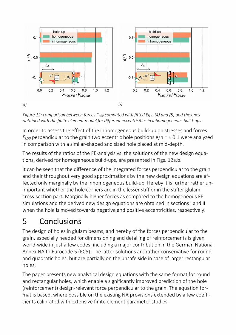
Figure 12: comparison between forces Ft,90 computed with fitted Eqs. (4) and (5) and the ones obtained with the finite element model for different eccentricities in inhomogeneous build-ups
In order to assess the effect of the inhomogeneous build-up on stresses and forces Ft,90 perpendicular to the grain two eccentric hole positions e/h = ± 0.1 were analyzed in comparison with a similar-shaped and sized hole placed at mid-depth.
The results of the ratios of the FE-analysis vs. the solutions of the new design equa-tions, derived for homogeneous build-ups, are presented in Figs. 12a,b.
It can be seen that the difference of the integrated forces perpendicular to the grain and their throughout very good approximations by the new design equations are af-fected only marginally by the inhomogeneous build-up. Hereby it is further rather un-important whether the hole corners are in the lesser stiff or in the stiffer glulam cross-section part. Marginally higher forces as compared to the homogeneous FE simulations and the derived new design equations are obtained in sections I and II when the hole is moved towards negative and positive eccentricities, respectively.
5 Conclusions The design of holes in glulam beams, and hereby of the forces perpendicular to the grain, especially needed for dimensioning and detailing of reinforcements is given world-wide in just a few codes, including a major contribution in the German National Annex NA to Eurocode 5 (EC5). The latter solutions are rather conservative for round and quadratic holes, but are partially on the unsafe side in case of larger rectangular holes.
The paper presents new analytical design equations with the same format for round and rectangular holes, which enable a significantly improved prediction of the hole (reinforcement) design-relevant force perpendicular to the grain. The equation for-mat is based, where possible on the existing NA provisions extended by a few coeffi-cients calibrated with extensive finite element parameter studies.

The present pronouncedly incorrectly specified force contribution by the bending moment in the NA document inevitably needs to be changed. As derivation of the new equations is essentially based on the FE analysis of holes placed at mid-depth of homogeneously built-up glulam beams, the effect of hole eccentricities and of inho-mogeneous beam build-ups has been checked exemplarily. It was found that the basic design equations apply well within the addressed realistic construction bounda-ries and eccentricities, as well as to inhomogeneous build-ups and, hence, are pro-posed for implementation in the new Eurocode 5.
6 References Aicher, S. (2011): Glulam Beams with Internally and Externally Reinforced Holes - Test
Detailing and Design. In: International Council For Research And Innovation In Building And Construction, Working Commission W18 - Timber Structures, Alghero, Italy.
Aicher, S. & Höfflin, L. (2001): Round holes in glulam members. Part 1: Analysis (in German), Bautechnik 78 :706-715.
Ardalany, M.; Fragiacomo, M.; Deam, B. & Carradine, D. (2012): Effect of Hole Loca-tion on the Load-Carrying Capacity of Laminated Veneer Lumber Beams, Australian Journal of Structural Engineering 13 :231-242.
Blaß, H.J., Ehlbeck, J., Kreuzinger, H. & Steck, G. (2004): Erläuterungen zu DIN 1052: 2004-08, Entwurf, Berechnung und Bemessung von Holzbauwerken, Deutsche Ge-sellschaft für Holzforschung, München
Danzer, M., Dietsch, P. & Winter, S. (2016): Reinforcement of round holes in glulam beams arranged eccentrically or in groups. In: CD-ROM Proceedings of the World Conference on Timber Engineering (WCTE 2016).
Eurocode 5 (2010): Design of timber structures - Part 1-1: General - Common rules and rules for buildings. CEN. (EN 1995-1-1).
EN 14080 (2013): Timber structures – Glued laminated timber and glued solid timber – Requirements; CEN.
EN 338 (2016): Structural timber – Strengths classes, CEN
German National Annex to EC5 (2013): German National Annex – Nationally deter-mined parameters – Eurocode 5: Design of timber structures – Part 1-1: General – Common rules and rules for buildings, DIN. (DIN EN 1995-1-1/NA)