improved depth map estimation from stereo images based … · improved depth map estimation from...
TRANSCRIPT

70 P. KAMENCAY, M. BREZNAN, R. JARINA, P. LUKAC, M. ZACHARIASOVA, IMPROVED DEPTH MAP ESTIMATION …
Improved Depth Map Estimation from Stereo Images Based on Hybrid Method
Patrik KAMENCAY, Martin BREZNAN, Roman JARINA, Peter LUKAC, Martina ZACHARIASOVA
1 Dept. of Telecommunications and Multimedia, University of Zilina, Univerzitna 8215/1, 010 26 Zilina, Slovakia
[email protected], [email protected], [email protected], [email protected], [email protected]
Abstract. In this paper, a stereo matching algorithm based on image segments is presented. We propose the hybrid segmentation algorithm that is based on a combination of the Belief Propagation and Mean Shift algorithms with aim to refine the disparity and depth map by using a stereo pair of images. This algorithm utilizes image filtering and modified SAD (Sum of Absolute Differences) stereo matching method. Firstly, a color based segmentation method is applied for segmenting the left image of the input stereo pair (reference image) into regions. The aim of the segmentation is to simplify representation of the image into the form that is easier to analyze and is able to locate objects in images. Secondly, results of the segmentation are used as an input of the local window-based matching method to determine the disparity estimate of each image pixel. The obtained experimental results demonstrate that the final depth map can be obtained by application of seg-ment disparities to the original images. Experimental re-sults with the stereo testing images show that our proposed Hybrid algorithm HSAD gives a good performance.
Keywords Image segmentation, disparity, Mean Shift, Belief propagation, SAD, HSAD, depth map, 3D image, stereo matching.
1. Introduction Recovery of 3D shape is a critical problem in many
vision application domains such as object modeling, scene understanding and high level visual activity recognition or robotics applications [3]. Obtaining a precise and accurate depth map is the ultimate goal for 3D shape recovery and 3D image reconstruction. The topic of the paper is focused on the process of the depth map computation from the images that are captured by the cameras placed in such positions so that a scene is taken from two slightly different views (angles). By using modern stereo vision systems, we can accurately estimate the depth. The Bumblebee stereo vision camera system from Point Grey Research is a two
lens camera and forms the basis of our research system [13]. This camera produces a disparity map in real time. A simple procedure for depth map generation from the stereo camera system of Point Grey is shown in Fig. 2.
Fig. 1. The Bumblebee stereo camera system by Point Grey
Research [13].
Disparity map computation is one of the key problems in 3D computer vision. A large number of algorithms have been proposed to solve this problem. However, since the problem is an ill-posed, a satisfying solution has not been found yet [1], [2]. An assignment of the stereo matching algorithm is to find such points in the both images that represent the same scene point.
Fig. 2. System platform overview [18].
For the epipolar rectified image pair, each point in the left image lies on the same horizontal line (epipolar line) as in the right image. This approach is used to reduce a search space for depth map computation algorithms. The depth of an image pixel is the distance of the corresponding space point from the camera center. To estimate the depth map and detect 3D objects, the corresponding pixels in the left and right images have to be matched. The proposed system for depth recovery starts with acquisition of images, which are calibrated and rectified. This algorithm consists of the following stages:

RADIOENGINEERING, VOL. 21, NO. 1, APRIL 2012 71
Image acquisition,
Epipolar geometry and image rectification,
Segmentation,
Stereo matching algorithm,
Depth map estimation.
First, radial and tangential lens distortion are removed by camera calibration, which gets intrinsic and extrinsic camera parameters. Knowledge of the camera parameters is utilized to rectify both images. After rectification, the image is segmented into regions by using the proposed hybrid segmentation algorithm. Finally, stereo matching algorithm is applied on the segmented left and right images with the aim to find all correspondences (matching points) and assign depth to each segment. Output of the stereo matching algorithm is the depth map.
The outline of the paper is as follows. In Section 2, an overview of the basic camera calibration is given. The image rectification based on segmentation is described in Section 3. The Belief Propagation and Mean Shift seg-mentation methods are presented in Section 4. In Sections 5 and 6, the process of disparity computation and the stereo matching algorithm are presented. Finally experimental results and implementation of the stereo matching algo-rithm are introduced in Section 7, and it is followed by conclusion in Section 8.
2. Camera Calibration In order to apply stereo ranging techniques with
a reasonable level of accuracy, it is important to calibrate the camera system. It is a process of finding the intrinsic and extrinsic parameters of the camera.
The classic calibration methods are based on specially prepared calibration patterns, objects with known dimen-sions and position in a certain coordinate system. Then features, such as corners and lines, are extracted from an image of the calibration pattern. Objects with meaning-ful features are usually chosen for calibration to be unam-biguously localized of their positions. A simple chessboard can serve for this purpose [4].
3. Image Rectification The image rectification is necessary for reducing
complexity of calculations for left and right images pixel correspondence. The purpose of the image rectification is to find the epipolar lines of two horizontally aligned images. This may be performed by using the linear trans-formations that rotate, translate and skew the camera images. Internal camera parameters and information about mutual camera positions and orientations are used in the transformations [5].
The 3D points are projected to the points in the left and right stereo images. After image rectification according Fig. 4, the epipolar lines of two projected points are paral-lel and horizontally aligned along the new image planes. The points are lying on the same epipolar line. The stereo matching problem is therefore reduced to one–dimensional search along horizontal lines, instead of two–dimensional search as it is shown in Fig. 4. More information on image rectification can be found in [5], [6].
3D Point
Centers of projection
epipolar lines
corresponding image point
Searching window
Fig. 3. Camera image before rectification.
Fig. 4. Camera image after rectification.
4. Color Image Segmentation In this section, two color segmentation methods are
described: Belief Propagation, and Mean Shift.
The goal of the image segmentation is to split the entire image into a set of segments that cover the image. The final segments must fulfill four conditions [7]:
n
ii RR
1
for all i and j, i j, there exists Ri Rj =0
for i = 1, 2, … , n, it must have P(Ri) = TRUE
for all i j, there exist P(Ri Rj) = FALSE
where R represents the whole image, Ri (i = 1, 2, … , n) are disjoint non-empty segments of R, P(Ri) is a uniformity predicate for all elements in Ri and 0 represents an empty set. Summation of segments should include all pixels in the image, what is the first condition. The second condition expresses, that the different segments should not overlap each other. The third condition expresses that the pixels in the same segment should have similar properties. The
72 P. KAMENCAY, M. BREZNAN, R. JARINA, P. LUKAC, M. ZACHARIASOVA, IMPROVED DEPTH MAP ESTIMATION …
pixels belonging to the different segments should have different properties, what is the last condition.
4.1 Belief Propagation
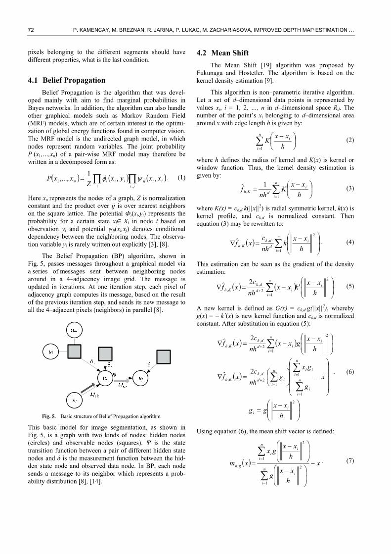
Belief Propagation is the algorithm that was devel-oped mainly with aim to find marginal probabilities in Bayes networks. In addition, the algorithm can also handle other graphical models such as Markov Random Field (MRF) models, which are of certain interest in the optimi-zation of global energy functions found in computer vision. The MRF model is the undirected graph model, in which nodes represent random variables. The joint probability P (x1,…,xn) of a pair-wise MRF model may therefore be written in a decomposed form as:
i ji
iiijiiin xxyxZ
xxP,
1 ,,1
,..., . (1)
Here xn represents the nodes of a graph, Z is normalization constant and the product over ij is over nearest neighbors on the square lattice. The potential Фi(xi,yi) represents the probability for a certain state xiXi in node i based on observation yi and potential ψij(xi,xj) denotes conditional dependency between the neighboring nodes. The observa-tion variable yi is rarely written out explicitly [3], [8].
The Belief Propagation (BP) algorithm, shown in Fig. 5, passes messages throughout a graphical model via a series of messages sent between neighboring nodes around in a 4–adjacency image grid. The message is updated in iterations. At one iteration step, each pixel of adjacency graph computes its message, based on the result of the previous iteration step, and sends its new message to all the 4–adjacent pixels (neighbors) in parallel [8].
Fig. 5. Basic structure of Belief Propagation algorithm.
This basic model for image segmentation, as shown in Fig. 5, is a graph with two kinds of nodes: hidden nodes (circles) and observable nodes (squares). Ψ is the state transition function between a pair of different hidden state nodes and δ is the measurement function between the hid-den state node and observed data node. In BP, each node sends a message to its neighbor which represents a prob-ability distribution [8], [14].
4.2 Mean Shift
The Mean Shift [19] algorithm was proposed by Fukunaga and Hostetler. The algorithm is based on the kernel density estimation [9].
This algorithm is non–parametric iterative algorithm. Let a set of d–dimensional data points is represented by values xi, i = 1, 2, …, n in d–dimensional space Rd. The number of the point’s xi belonging to d–dimensional area around x with edge length h is given by:
n
i
i
h
xxK
1
(2)
where h defines the radius of kernel and K(x) is kernel or window function. Thus, the kernel density estimation is given by:
n
i
idKh h
xxK
nhf
1,
1ˆ (3)
where K(x) = ck,d.k(||x||2) is radial symmetric kernel, k(x) is kernel profile, and ck,d is normalized constant. Then equation (3) may be rewritten to:
n
i
id
dkKh h
xxk
nh
cxf
1
2,
,ˆ . (4)
This estimation can be seen as the gradient of the density estimation:
2
12
,,
2ˆh
xxkxx
nh
cxf i
n
iid
dkKh
. (5)
A new kernel is defined as G(x) = ck,d.g(||x||2), whereby g(x) = – k´(x) is new kernel function and ck,d is normalized constant. After substitution in equation (5):
2
1
1
12
,,
1
2
2
,,
2ˆ
2ˆ
h
xxgg
xg
gxg
nh
cxf
h
xxgxx
nh
cxf
ii
n
ii
n
iiin
iid
dkKh
n
i
iid
dkKh
. (6)
Using equation (6), the mean shift vector is defined:
x
h
xxg
h
xxgx
xmn
i
i
n
i
ii
gh
1
2
1
2
,. (7)

RADIOENGINEERING, VOL. 21, NO. 1, APRIL 2012 73
The Mean Shift algorithm is based on iterative computing of the mean shift vector and consistently actualizing kernel’s position by equation xk+1 = xk + m(xk) [8], [15], [19].
4.3 Hybrid Algorithm
In the image segmentation, hybrid methods combine two or more different image segmentation algorithms. Examples of hybrid algorithms are in [10]. Here we exam-ine the hybrid algorithm that is created by a combination of the two techniques: Belief Propagation [8] and the Mean Shift segmentation algorithms [19]. This approach com-bines the advantages of both segmentation methods. The Mean Shift algorithm is fast and Belief Propagation is very accurate segmentation.
Fig. 6. Block diagram of hybrid segmentation algorithm using
image filtering.
First, we apply image filtering by Mean Shift algo-rithm. This step is very useful for noise removing, smooth-ing and image segmentation. For each pixel of an image, the set of neighboring pixels is determined. Let Xi be the input and Yi filtered image, where i = 1, 2, … ,n. The filter-ing algorithm comprises of the following steps [16], [20], [21]:
Initialize j = 1 and yi,1 = pi.
Compute through the Mean Shift the mode where the pixel converges.
Store the component of the gray level of the calculated value Zi = (xi, yi,c) at Zi , where xi is the spatial component and yi,c is the range component.
Secondly, the image is split into segments using Mean Shift algorithm. In the third step, means of segments are retrieved by applying mean shift theory. Fourth, the small segments are merged together to the most similar adjacent segments by the Belief propagation method. Finally, we have integrated our proposed hybrid segmentation algo-rithm with the Sum-of-Absolute-Differences (SAD) stereo matching algorithm. This hybrid SAD method (HSAD) is able to produce highly accurate depth map.
5. Disparity Calculation In this section, we describe the process of disparity
computation where input images are segmented first and then the same matching points in the left and right images are found. This procedure plays a very important role in our proposed stereo system.
This idea is illustrated for an arbitrarily located 3D point P in Fig. 7. Let a distant object is viewed by two cameras positioned in the same orientation but separated by a distance known as the baseline. Then, the object will appear in a similar position in both stereo images. The distance between the objects in left and right images is known as disparity d defined by (8), where xL and xR are x coordinates of the projected 3D coordinate onto the left and right image planes IL and IR [11].
p
p
p
pRL z
lx
z
lxfxxd , (8)
d
fB
d
flz p
2. (9)
Since the left and the right camera image planes are located in the same plane, y-coordinates of these two images are the same (yL=yR), and the disparity equals to the difference between the horizontal coordinates (xL-xR).
P = (xp , yp , zp)
Z
xRxL
ffIL IR
l l
Fig. 7. A simple stereo system [11].
This means that once the disparity is computed, depth may in turn be found for the camera parameters: focal length f and baseline distance B=2l.
6. Stereo Matching Algorithm A reconstruction of the disparity map from the left
and right stereo pair is known as the stereo matching algo-rithm. The detection feature points must be matched. There exist several matching techniques based on various algo-rithms, e.g. Correlation (C), Normalized Cross Correlation (NCC), Sum of Squared Differences (SSD) and Sum of Absolute Differences (SAD) algorithms.

74 P. KAMENCAY, M. BREZNAN, R. JARINA, P. LUKAC, M. ZACHARIASOVA, IMPROVED DEPTH MAP ESTIMATION …
The SAD algorithm (10) is one of the simplest of dissimilarity measures of the left and right stereo images corresponding with square windows. Hence, the algorithm described in the next section, was chosen for the proposed algorithm.
6.1 Sum of Absolute Differences
It computes the intensity differences for each center pixel (i, j) in a window W(x, y) as follows:
N
yxWjiRL jdiIjiIdyxSAD
,,
,,,, (10)
where IL and IR are pixel intensity functions of the left and right image, respectively. W(x, y) is square window that surrounds the position (x, y) of the pixel. The disparity SAD (x, y, d) calculation is repeated within the x-coordi-nate frame in the image row, defined by zero and maxi-mum possible disparity dmax of the searched 3D scene. The minimum difference value over the frame indicates the best matching pixel, and position of the minimum defines the disparity of the actual pixel [11], [18].
Quality of 3D disparity map depends on square win-dow size, because a bigger window size corresponds to a greater probability of correct pixel disparity calculated from matched points, although the calculation gets slower [12].
6.2 Sum of Squared Differences
The area-based SSD algorithm is similar to the previ-ously described SAD algorithm. Instead of computing the absolute value, the SSD computes squares of the intensity differences as follows:
N
yxWjiRL jdiIjiIdyxSSD
,,
2,,,, (11)
here IL and IR are pixel intensity functions of the left and right image, respectively. W(x, y) is square window that surrounds the position (x, y) of the pixel [18].
6.3 Feature Matching
The feature matching algorithm improves precision of the disparity calculation. This kind of algorithms extracts object’s suitable features in 3D scene, e.g. segments of edges or contours in the left and right stereo images. In the following stage, the disparity map is calculated from the corresponding points of the features. The matching algo-rithm based on the proposed hybrid segmentation is much faster, since a small portion of all the left and right images pixels are used for matching, while only precision is taken into account. Although note the calculated disparity map is sparse [13]. A final depth map is then calculated from disparity map according to the relation (8).
7. Experimental Results In this section, some of the obtained experimental
results on reconstructed depth map will be presented. All the experiments were implemented in Matlab.
Input data from left
image
Input data from right
image
Find out the matching points
Minimum cost search
Fill the matching range
Original left
image
Original right
image
Undistorsion and Rectification
Rectified left
image
Rectified right
image
Filter/Detector
Hybrid segmentation
Segmented map
Stereo SAD with border
filter correction
HSAD algorithm
SAD algorithm
Hybrid segmentation
Proposed approach
Stereo matching with SAD algorithm
Initial segmentation by
MeanShift algorithm
Merge segments by BP
Application Belief
Propagation
Retrieving of segments by
Mean Shift theory
Strereo depth map
Final segmentation (Mean Shift + BP)
Fig. 8. Block diagram of proposed approach using HSAD
(combines SAD algorithm and hybrid segmentation).
The set of all parameters used in our hybrid segmen-tation algorithm, is shown in Tab. 1. Spatial resolution parameter s affects smoothing, connectivity of segments (chosen according to the window size). Range resolution parameter r affects at number of segments (it shall be kept low if contrast is also low). Next, S is a size of the smallest segment, Min_sh is minimum shift, Max_sh is maximum shift, sm is a penalty term for violating the smoothness constraint, T is threshold, and finally P is a penalty term, which will increase the penalty if the gradient has a small magnitude.
Hybrid segmentation parameters s r S Min_sh 9 5 15 1
sm T P Max_sh 30 7 4 40
Tab. 1. Parameters used in hybrid segmentation algorithm.
a) b) Fig. 9. Image processed by, a) filtration algorithm, b) hybrid
segmentation algorithm.

RADIOENGINEERING, VOL. 21, NO. 1, APRIL 2012 75
The developed hybrid segmentation algorithm, as the first step, performs smoothing filtration of input image data following by the segmentation process [17]. The filtered image is shown in Fig. 9a and the segmented image after filtration in Fig. 9b.
The rectified left and right images are shown in Fig. 10. Both images were segmented by the proposed hybrid segmentation algorithm.
Fig. 10. Correspondence using window – based matching
(rectified images).
All disparity map pixels of all the segments were ob-tained using SAD method along the same epipolar lines of the stereo images as it is shown in Fig. 10. The minimum value over the row in the right image is chosen to be the best matching pixel (see Fig. 11). The disparity is then calculated as the actual horizontal pixel difference [18].
Fig. 11. Stereo matching – best match.
The result of stereo matching process is a grayscale disparity map that indicates the disparity for every pixel with corresponding intensity. Lighter areas in Fig. 12 are closer to the camera, darker ones further away. Black areas are points, where disparity was unable to be calculated. Moreover, the depth of each pixel can be computed from the disparity map according to the relation (8).
Fig. 12. Disparity map recovery using hybrid algorithm from
stereoscopic pair images.
The depth maps of each of the implemented algo-rithms are shown in Fig. 13 and Fig. 14. Both algorithms compute the depth for all pixels with window sizes dimen-sion at square of 9x9 pixels. One may easily see that the implementation of the stereo matching method based on the SAD algorithm using the proposed hybrid segmentation provides much better depth map, than the implementation of the SAD algorithm without segmentation. In Fig. 13, the comparison of the depth map produced by SAD and SSD algorithms are shown. In our case, the SAD algorithm was selected for further investigations and experiments. Reason for choice the SAD algorithm is the fact that SSD algo-rithm spends more time for computing the disparity map (see Tab. 2 and Tab. 3).
Fig. 13. Results of depth maps produced by: a) SAD, b) SSD.
Fig. 14. Depth map of the hybrid segmentation method imple-
mentation.
The hybrid segmentation algorithm (see Fig. 8) in a combination with SAD stereo matching method is ap-plied to refine the final depth map (see Fig. 14). Both, the stereo matching algorithms based on SAD method without segmentation and the proposed hybrid approach based on hybrid segmentation method were efficient. The resulting images were computed on the 2.27 GHz Intel Core i3 proc-essor with 4 GB DDR3 memory. The computational time for SAD algorithm was approximately 105 seconds and for hybrid segmentation method (HSAD) 29 seconds, respec-tively. The stereo matching algorithm based on HSAD seems to be more effective algorithm to producing the cleaner disparity map with the homogeneous areas. On the other side, the stereo matching algorithm based on SAD method produced a clear depth estimation of the scene. Moreover, it generates a higher level of errors caused by occlusion of image segments.
Resolution Window Time [s] 400x266 3x3 47 400x266 5x5 59 400x266 9x9 105
Tab. 2. Results of the SAD implementation.
76 P. KAMENCAY, M. BREZNAN, R. JARINA, P. LUKAC, M. ZACHARIASOVA, IMPROVED DEPTH MAP ESTIMATION …
Resolution Window Time [s] 400x266 3x3 108 400x266 5x5 335 400x266 9x9 897
Tab. 3. Results of the SSD implementation.
In the next experiment, the proposed hybrid approach was tested on four real stereo images taken by the stereo camera system. This algorithm was applied for disparity estimation of 9x9 blocks from the reference left image by searching the corresponding candidate blocks of the right image (see Fig. 10). It was applied to the stereo images taken by our stereoscopic camera. Our testing dataset con-sisted of 25 real stereo image pairs in gray scale with the size 800x600 pixels. Final disparity maps of four test stereoscopic images, namely books, racket, cube and building are presented in Fig. 15. In detail, the Fig. 15b shows the disparity maps created by SAD algorithm with-out segmentation and Fig. 15c the results by hybrid seg-mentation algorithm. Disparity maps produced by the Bumblebee stereoscopic camera are shown in Fig. 15d.
Fig. 15. Experimental results on our four test grayscale images:
a) reference images, b) disparity map after using SAD algorithm without segmentation, c) result of our hybrid algorithm HSAD, d) Bumblebee camera system.
Quality of disparity map is represented as percentage of pixels with disparity errors (bad matching pixels) [18]:
X
i
Y
jTC jidjid
YXP
1 1
,,*
1 (12)
where X*Y represent the size of the image, dC is the com-puted disparity map of the test image and dT is the truth disparity map. The ground truth disparity map [1], [22] is the inverse of the ground truth distance. Equation (13) shows how to calculate the ground truth disparity map from the depth map.
hD
fBId
T
REST (13)
where DT is ground truth depth map, h is height from the ground plane, DT*h is ground truth distance, B is baseline between the cameras, IRES is image resolution and f is focal length.
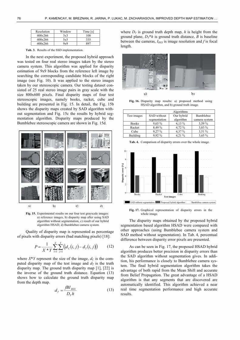
Fig. 16. Disparity map results: a) proposed method using
HSAD algorithm, and b) ground truth image.
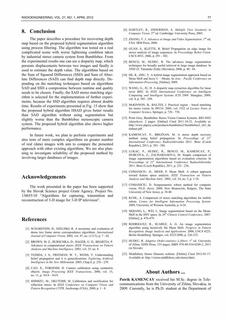
Algorithms Test images SAD without
segmentation Our hybrid algorithm
Bumblebee camera system
Books 9,65 % 4,13 % 3,59 % Racket 8,49 % 4,72 % 3,83 % Cube 9,27 % 4,37 % 3,51 %
Building 9,92 % 4,21 % 3,65 %
Tab. 4. Comparison of disparity errors over the whole image.
Books Racket Cube Building0
2
4
6
8
10
Test images
Dis
par
ity
erro
r [%
]
SAD without segmentation Proposed hybrid algorithm Bumblebee camera system
Fig. 17. Graphical representation of disparity errors in the whole image.
The disparity maps obtained by the proposed hybrid segmentation based algorithm HSAD were compared with other approaches (using Bumblebee camera system and SAD method without segmentation). In Tab. 4, percentual difference between disparity error pixels are presented.
As can be seen in Fig. 17, the proposed HSAD hybrid algorithm produces better precision in disparity errors than the SAD algorithm without segmentation gives. In addi-tion, his performance is closely to Bumblebee camera sys-tem. The final hybrid segmentation algorithm takes the advantage of both rapid from the Mean Shift and accurate from Belief Propagation. The great advantage of a HSAD algorithm is that any segments that are discovered are automatically identified. This algorithm achieved a near real time segmentation performance and high accurate results.
RADIOENGINEERING, VOL. 21, NO. 1, APRIL 2012 77
8. Conclusion The paper describes a procedure for recovering depth
map based on the proposed hybrid segmentation algorithm using process filtering. The algorithm was tested on a real complicated scene with worse lightening condition taken by industrial stereo camera system from Bumblebee. From the experimental results one can see a disparity map, which presents displacements between two images and finally is used to estimate the depth value. The algorithms based on the Sum of Squared Differences (SSD) and Sum of Abso-lute Differences (SAD) can find depth map directly. De-pending on the matching techniques based on algorithms SAD and SSD a compromise between runtime and quality needs to be chosen. Finally, the SAD stereo matching algo-rithm is selected for the implementation of further experi-ments, because the SSD algorithm requires almost double time. Results of experiments presented in Fig. 15 show that the proposed hybrid algorithm HSAD gives better results than SAD algorithm without using segmentation but slightly worse than the Bumblebee stereoscopic camera system. The proposed hybrid algorithm also shows higher performance.
In future work, we plan to perform experiments and also tests of more complex algorithms on greater number of real (data) images with aim to compare the presented approach with other existing algorithms. We are also plan-ning to investigate reliability of the proposed method by involving larger databases of images.
Acknowledgements
The work presented in the paper has been supported by the Slovak Science project Grant Agency, Project No. 1/0655/10 “Algorithms for capturing, transmition and reconstruction of 3-D image for 3-D IP television”.
References
[1] SCHARSTEIN, D., SZELISKI, R. A taxonomy and evaluation of dense two frame stereo correspondence algorithms. International Journal of Computer Vision, 2002, vol. 47, no. (1/2/3), p. 7 - 42.
[2] BROWN, M. Z., BURSCHKA, D., HAGER, G. D., BHARTIA, P. Advances in computational stereo. IEEE Transactions on Pattern Analysis and Machine Intelligence, 2003, vol. 25, no. 8.
[3] YEDIDA, J. S., FREEMAN, W. T., WEISS, Y. Understanding belief propagation and it is generalizations. Exploring Artificial Intelligence in the New Millennium. 2003, Chap.8, p. 236 - 239.
[4] CAO, X., FOROOSH, H. Camera calibration using symmetric objects. Image Processing IEEE Transactions, 2006, vol. 15, no. 11, p. 3614 - 3619.
[5] SHIMIZU, M., OKUTOMI, M. Calibration and rectification for reflection stereo. In IEEE Conference on Computer Vision and Pattern Recognition CVPR. Anchorage (USA), 2008, p. 1 - 8.
[6] HARTLEY, R., ZISSERMAN, A. Multiple View Geometry in Computer Vision. 2nd ed. Cambridge: University Press, 2005.
[7] ZHANG, Y. J. Advances in Image and Video Segmentation. 1nd ed. USA: IRM Press, 2006.
[8] GUAN, S., KLETTE, R. Belief Propagation on edge image for stereo analysis of image sequences. In Proceedings Robot Vision. LNCS 4931, 2006, p. 291 - 302.
[9] BENCO, M., HUDEC, R. The advances image segmentation techniques for broadly useful retrieval in large image database. In NSSS IX. Tatranske Zruby (Slovakia), 2006, p. 40 - 44.
[10] HE, R., ZHU, Y. A hybrid image segmentation approach based on Mean Shift and fuzzy C – Means. In Asia – Pacific Conference on Information Processing. [Online], 2009.
[11] WANG, G., JU, H. A disparity map extraction algorithm for lunar rover BH2. In IEEE International Conference on Intelligent Computing and Intelligent Systems ICIS 2009. Shanghai, 2009, vol. 4, p. 385 - 389.
[12] McKINNON, B., BALTES, J. Practical region – based matching for stereo vision. In IWCIA. 2005, vol. 3322 of Lecture Notes in Computer Science, Springer, p. 726 - 738.
[13] Point Grey, Bumblebee Stereo Vision Camera Systems. BB2-08S2 (datasheet). 2 pages. [Online] Cited 2011-10-23. Available at: http://www.ptgrey.com/products/bumblebee2/bumblebee2_xb3_datasheet.pdf
[14] KAMENCAY, P., BREZNAN, M. A stereo depth recovery method using belief propagation. In Proceedings of 21st International Conference Radioelektronika 2011. Brno (Czech Republic), 2011, p. 383 - 386.
[15] LUKAC, P., HUDEC, R., BENCO, M., KAMENCAY, P., DUBCOVA, Z., ZACHARIASOVA, M. Simple comparison of image segmentation algorithms based on evaluation criterion. In Proceedings of 21st International Conference Radioelektronika 2011. Brno (Czech Republic), 2011, p. 233 - 236.
[16] COMANICIU, D., MEER, P. Mean Shift: A robust approach toward feature space analysis. IEEE Transaction on Pattern Analysis and Machine Intel., 2002, vol. 24, no. 5, p. 1-18.
[17] COMANICIU, D. Nonparametric robust method for computer vision. Ph.D. thesis. 2000, New Brunswick, Rutgers, The State University of New Jersey, p. 38-40.
[18] KUHL, A. Comparison of stereo matching algorithms for mobile robots. Centre for Intelligent Information Processing System. 2005, University of Western Australia, p. 4-24.
[19] SIQIANG, L., WEI, L. Image segmentation based on the Mean-Shift in the HSV space. In 26th Chinese Control Conference, 2007. [Online], p. 476-479.
[20] RODRIGUEZ, R., SUAREZ, A. G. An image segmentation algorithm using iteratively the Mean Shift. Progress in Pattern Recognition, Image Analysis and Applications. 2006, LNCS 4225, Berlin Heidelberg: Springer, vol. 4225/2006, p. 326-335.
[21] HUDEC, R. Adaptive Order-statistics L-filters. 1st ed. University of Zilina: EDIS Press, 155 pages, ISBN 978-80-554-0248-2, 2011 (in Slovak).
[22] Middlebury Stereo Datasets website. [Online] Cited 2012-01-17. Available at: http://vision.middlebury.edu/stereo/data/.
About Authors ... Patrik KAMENCAY received his M.Sc. degree in Tele-communications from the University of Zilina, Slovakia, in 2009. Currently, he is Ph.D. student at the Department of

78 P. KAMENCAY, M. BREZNAN, R. JARINA, P. LUKAC, M. ZACHARIASOVA, IMPROVED DEPTH MAP ESTIMATION …
Telecommunications and Multimedia of the University of Zilina. His doctoral work is in the area of 3D image proc-essing. His research interests include holography for 3D display, and construction of 3D images of the original objects.
Martin BREZNAN received his M.Sc. and Ph.D. degrees in Telecommunications from the University of Zilina, Slo-vakia, in 1985 and 2004, respectively. His Ph.D. research work was oriented to reconstruction of 3D images from stereo pictures. At present he works as a lecturer in Digital Signal Processing at the Department of Telecommunica-tions and Multimedia. His research interests are oriented towards algorithms for 3D model reconstruction from both scenes taken by stereo or multi camera system.
Roman JARINA received his Ph.D. degree in Telecom-munications from the Faculty of Electrical Engineering, University of Zilina, in 2000. In 2000-2002 he was with Dublin City University, Ireland, where he was engaged in research in the Centre for Digital Video Processing. Cur-rently, he is Associate Professor and head of Digital Signal
Processing group at the Department of Telecommunication and Multimedia. He serves as a national delegate in EU Actions COST 292 „Semantic Multimodal Analysis of Digital Media“ and COST IC1003-QUALINET. He is also a member of the Scientific Advisory Board of the EU FP7 Network of Excellence „3D life“ project. His research interests also include digital signal processing, audio and speech processing. Dr. Jarina is a member of IEEE Signal Processing Society, IET and AES.
Peter LUKAC received his M.Sc. degree in Telecommu-nications at Faculty of Electrical Engineering, University of Zilina, Slovakia, in 2008. Currently, he completed his doctoral studies on evaluation of algorithms for color image segmentation.
Martina ZACHARIASOVA received her M. Sc. degree in Telecommunications from the University of Zilina, in 2010. Currently, she is PhD. student at the Department of Telecommunications and Multimedia. Her doctoral work is in area of semantic analysis of web document. Her research interests include semantic description of images.