important - p11.secure.hostingprod.comsite.electricsuppliesonline... · case 24 gauge galvanized...
TRANSCRIPT

1
SH, VH & SE Models
INSTALLATION, OPERATION AND MAINTENANCE MANUAL
SH704 • VH704 • SE704
Your ventilation system should be installed in conformance with the appropriate provincial or state requirementsor in the absence of such requirements with the current edition of the National Building Code, and / orASHRAE’s “ Good Engineering Practices”.
IMPORTANT - PLEASE READ THIS MANUALBEFORE INSTALLING UNIT
CAUTION - Before installation, careful consideration must be given to how this system
will operate if connected to any other piece of mechanical equipment, i.e. a forced air furnace
or air handler, operating at a higher static. After installation, the compatibility of the two
pieces of equipment should be confirmed by measuring the airflow’s of the Heat Recovery or
Energy Recovery Ventilators.
It is always important to assess how the operation of any HRV/ERV may interact with vented
combustion equipment (i.e. Gas Furnaces, Oil Furnaces, Wood Stoves, etc.).
NEVER - install a ventilator in a situation where its normal operation, lack of operation or
partial failure may result in the backdrafting or improper functioning of vented combustion
equipment!!!
SH, VH & SE SeriesHeat & Energy Recovery Ventilators

2
TABLE OF CONTENTSTECHNICAL DATA
SH704 3VH704 5SE704 7
INSTALLATION 9Mounting the Unit 9Location & Ducting 10Examples 12Air Flow Balancing 16
MAINTENANCE 17
TROUBLESHOOTING 18
ELECTRICAL CONNECTIONS 19
The Best Limited Warranty in the Business
• The heat recovery aluminum core has alimited lifetime warranty and the enthalpyenergy recovery core has a 5 year limitedwarranty.
• The motors found in all Fantech HRV/ERVsrequire no lubrication, and are factorybalanced to prevent vibration and promotesilent operation.
• The limited warranty covers normal use.It does not apply to any defects,malfunctions or failures as a result ofimproper installation, abuse, mishandling,misapplication, fortuitous occurrence orany other circumstances outsideFantech’s control.
• Inappropriate installation or maintenance may result in thecancellation of the warranty.
• Any unauthorized work will result in the cancellation of the warranty.
• Fantech is not responsible for any incidental or consequential damagesincurred in the use of the ventilationsystem.
• Fantech is not responsible for providingan authorized service centre near thepurchaser or in the general area.
• Fantech reserves the right to supplyrefurbished parts as replacements.
• Transportation, removal and installationfees are the responsibility of the purchaser.
• The purchaser is responsible to adheringto all codes in effect in his area.
• The warranty is limited to 5 years onparts and 7 years on the motor from thedate of purchase, including parts replacedduring this time period. If there is noproof of purchase available, the dateassociated with the serial number will beused for the beginning of the warrantyperiod.
* This warranty is the exclusive and onlywarranty in effect relative to the ventilationsystem and all other warranties eitherexpressed or implied are invalid.
Sizing (Example) for minimum airflow normally required.HRV/ERV units are typically sized to ventilate at 0.35 air changes per hour. To calculate, sim-ply take the square footage of the space and multiply by the height of the ceiling to get cubicvolume. Then, divide by 60 and multiply by 0.35.Example: Total SQFT 1100
Height of ceiling x 8Cubic volume 8800
/ 60147
x 0.35Airflow required (CFM) 51 cfm total
* Always consult your local code for sizing requirements in your area.* If additional exhaust capacity is required, installation of a fantech bath kit in main bath area
is recommended.
***Illustrations &images in this
manual may not beexactly like unit purchase, theseillustrations &images are for
examples only.***
ASHRAE Standard 62.2 - 2004Sizing (Example) for minimum airflow normally required.
Ventilation Air Requirements, cfm Ventilation Air requirements, L/s
3
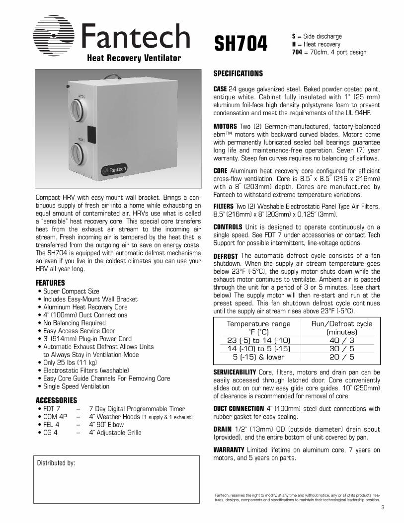
SH704
Compact HRV with easy-mount wall bracket. Brings a con-tinuous supply of fresh air into a home while exhausting anequal amount of contaminated air. HRVs use what is calleda “sensible” heat recovery core. This special core transfersheat from the exhaust air stream to the incoming airstream. Fresh incoming air is tempered by the heat that istransferred from the outgoing air to save on energy costs.The SH704 is equipped with automatic defrost mechanismsso even if you live in the coldest climates you can use yourHRV all year long.
FEATURES• Super Compact Size• Includes Easy-Mount Wall Bracket• Aluminum Heat Recovery Core• 4˝ (100mm) Duct Connections• No Balancing Required• Easy Access Service Door• 3’ (914mm) Plug-in Power Cord• Automatic Exhaust Defrost Allows Units
to Always Stay in Ventilation Mode • Only 25 lbs (11 kg)• Electrostatic Filters (washable)• Easy Core Guide Channels For Removing Core• Single Speed Ventilation
ACCESSORIES• FDT 7 – 7 Day Digital Programmable Timer• COM 4P – 4˝ Weather Hoods (1 supply & 1 exhaust)• FEL 4 – 4˝ 90˚ Elbow• CG 4 – 4˝ Adjustable Grille
SPECIFICATIONS
CASE 24 gauge galvanized steel. Baked powder coated paint,antique white. Cabinet fully insulated with 1" (25 mm)aluminum foil-face high density polystyrene foam to preventcondensation and meet the requirements of the UL 94HF.
MOTORS Two (2) German-manufactured, factory-balancedebm™ motors with backward curved blades. Motors comewith permanently lubricated sealed ball bearings guaranteelong life and maintenance-free operation. Seven (7) yearwarranty. Steep fan curves requires no balancing of airflows.
CORE Aluminum heat recovery core configured for efficientcross-flow ventilation. Core is 8.5˝ x 8.5˝ (216 x 216mm)with a 8˝ (203mm) depth. Cores are manufactured byFantech to withstand extreme temperature variations.
FILTERS Two (2) Washable Electrostatic Panel Type Air Filters,8.5˝ (216mm) x 8˝ (203mm) x 0.125˝ (3mm).
CONTROLS Unit is designed to operate continuously on asingle speed. See FDT 7 under accessories or contact TechSupport for possible intermittent, line-voltage options.
DEFROST The automatic defrost cycle consists of a fanshutdown. When the supply air stream temperature goesbelow 23°F (-5°C), the supply motor shuts down while theexhaust motor continues to ventilate. Ambient air is passedthrough the unit for a period of 3 or 5 minutes. (see chartbelow) The supply motor will then re-start and run at thepreset speed. This fan shutdown defrost cycle continuesuntil the supply air stream rises above 23°F (-5°C).
SERVICEABILITY Core, filters, motors and drain pan can beeasily accessed through latched door. Core convenientlyslides out on our new easy glide core guides. 10˝ (250mm)of clearance is recommended for removal of core.
DUCT CONNECTION 4˝ (100mm) steel duct connections withrubber gasket for easy sealing.
DRAIN 1/2˝ (13mm) OD (outside diameter) drain spout(provided), and the entire bottom of unit covered by pan.
WARRANTY Limited lifetime on aluminum core, 7 years onmotors, and 5 years on parts.
Heat Recovery Ventilator
S = Side dischargeH = Heat recovery704 = 70cfm, 4 port design
Temperature range Run/Defrost cycle˚F (˚C) (minutes)
23 (-5) to 14 (-10) 40 / 314 (-10) to 5 (-15) 30 / 5
5 (-15) & lower 20 / 5
Distributed by:
Fantech, reserves the right to modify, at any time and without notice, any or all of its products’ fea-tures, designs, components and specifications to maintain their technological leadership position.

4
United States1712 Northgate Blvd., Sarasota, FL. 34234(T) 1.800.747.1762 (F) 1.800.487.9915(T) 1.941.309.6000(F) [email protected]
Canada50 Kanalflakt Way, Bouctouche, NB E4S 3M5(T) 1.800.565.3548(F) 1.877.747.8116(T) 1.506.743.9500(F) [email protected]
Article #: 412120Rev Date: 120805
Dimensions & Airflow - All units feature three foot plug-in power cord with 3-prong plug.
Pa in wg L/s cfm L/s cfm L/s cfm25 0.1 45 96 47 99 49 10450 0.2 40 85 41 88 41 8875 0.3 32 67 33 69 34 72100 0.4 26 56 27 58 28 58125 0.5 20 42 20 43 20 43
EXT. STATICPRESSURE
NET SUPPLYAIR FLOW
GROSS AIR FLOWSUPPLY EXHAUST
˚C ˚F L/s cfmHeating 0 32 26 55 36 57 67 –
0 32 32 68 40 55 63 –0 32 39 83 40 54 60 –
-25 -13 34 72 35 53 66 –
SUPPLY TEMPERATURE
NETAIRFLOW
Ventilation Performance
Energy Performance
POWER CONSUMED
WATTS
SENSIBLERECOVERYEFFICIENCY
APPARENT SENSIBLE
EFFECTIVENESS
LATENT RECOVERY/MOISTURE
TRANSFER
Submitted by: Date:
Qty: Model #:
Comments:
Project #:
Location:
Architect:
Engineer:
Contractor:
0
0.1
0.2
0.3
0.4
0.5
0.6
0 25 50 75 100 125 150cfm (l/s = n x 0.47)
in w
.g. (
Pa =
n x
248
) Net Supply
Net Exhaust
Specifications and Ratings• Model: SH704• Total assembled weight: 25 lbs (11kg)• Cabinet: 24 ga. steel w/powder coat finish• Motors: ebm motors w/backward curved blades• Filters: 2 washable electrostatic filters
8.5˝ (216mm) x 8˝ (205mm) x 0.125˝ (3mm)
• Insulated with 1" (25 mm) aluminum foil-facehigh density polystyrene foam to prevent con-densation and meet the requirements of theUL 94HF.
• Core: Aluminum8.5˝ (216mm) x 8.5˝ (216mm) x 8˝ (205mm)
• Supply & exhaust ducts: 4˝ (100mm)• Mounting: Wall bracket included• Electrical requirements:
Volts Frequency Amps Watts115V 60Hz 0.36A 40W3' plug-in power cord w/ 3-prong plug
Contacts
• Continuous ventilation mode of supply and exhaust airstreams• 10˝ (254mm) of clearance is recommended for removal of core

5
VH704
Compact top port design HRV with easy-mount wall bracket.Brings a continuous supply of fresh air into a home whileexhausting an equal amount of contaminated air. HRVs usewhat is called a “sensible” heat recovery core. This specialcore transfers heat from the exhaust air stream to theincoming air stream. Fresh incoming air is tempered by theheat that is transferred from the outgoing air to save onenergy costs. The VH704 is equipped with automatic defrostmechanisms so even if you live in the coldest climates youcan use your HRV all year long.
FEATURES• Super Compact Size• Top Port Design Fits in Tight Spaces• Includes Easy-Mount Wall Bracket• Aluminum Heat Recovery Core• 4” (100mm) Duct Connections• No Balancing Required• Easy Access Service Door• 3’ (914mm) Plug-in Power Cord• Automatic Exhaust Defrost Allows Units
to Always Stay in Ventilation Mode • Only 26 lbs (12 kg)• Electrostatic Filters (washable)• Easy Core Guide Channels For Removing Core• Single Speed Ventilation
ACCESSORIES• FDT 7 – 7 Day Digital Programmable Timer• COM 4P – 4˝ Weather Hoods (1 supply & 1 exhaust)• FEL 4 – 4˝ 90˚ Elbow• CG 4 – 4˝ Adjustable Grille
SPECIFICATIONS
CASE 24 gauge galvanized steel. Baked powder coated paint,antique white. Cabinet fully insulated with 1" (25 mm)aluminum foil-face high density polystyrene foam to preventcondensation and meet the requirements of the UL 94HF.
MOTORS Two (2) German-manufactured, factory-balancedebm™ motors with backward curved blades. Motors comewith permanently lubricated sealed ball bearings toguarantee long life and maintenance-free operation. Seven(7) year warranty. Steep fan curves requires no balancing ofairflows.
CORE Aluminum heat recovery core configured for efficientcross-flow ventilation. Core is 8.5˝ x 8.5˝ (216 x 216 mm)with a 8˝ (205 mm) depth. Cores are manufactured byFantech to withstand extreme temperature variations.
FILTERS Two (2) Washable Electrostatic Panel Type Air Filters,8.5˝ (216mm) x 8˝ (203mm) x 0.125˝ (3mm).
CONTROLS Unit is designed to operate continuously on asingle speed. See FDT 7 under accessories or contact TechSupport for possible intermittent, line-voltage options.
DEFROST The automatic defrost cycle consists of a fanshutdown. When the supply air stream temperature goesbelow 23°F (-5°C), the supply motor shuts down while theexhaust motor continues to ventilate. Ambient air is passedthrough the unit for a period of 3 or 5 minutes. (see chartbelow) The supply motor will then re-start and run at thepreset speed. This fan shutdown defrost cycle continuesuntil the supply air stream rises above 23°F (-5°C).
SERVICEABILITY Core, filters, motors and drain pan can beeasily accessed through latched door. Core convenientlyslides out on our new easy glide core guides. 10˝ (250mm)of clearance is recommended for removal of core.
DUCT CONNECTION 4˝ (100mm) steel duct connections withrubber gasket for easy sealing.
DRAIN 1/2˝ (13mm) OD (outside diameter) drain spoutprovided, entire bottom of unit covered by pan.
WARRANTY Limited lifetime on aluminum core, 7 year onmotors, and 5 year on parts.
Heat Recovery Ventilator
V = Vertical dischargeH = Heat recovery704 = 70cfm, 4 port design
Temperature range Run/Defrost cycle˚F (˚C) (minutes)
23 (-5) to 14 (-10) 40 / 314 (-10) to 5 (-15) 30 / 5
5 (-15) & lower 20 / 5
Distributed by:
Fantech, reserves the right to modify, at any time and without notice, any or all of its products’ fea-tures, designs, components and specifications to maintain their technological leadership position.

6
Dimensions & Airflow - All units feature three foot plug-in power cord with 3-prong plug.
Submitted by: Date:
Qty: Model #:
Comments:
Project #:
Location:
Architect:
Engineer:
Contractor:
Specifications and Ratings• Model: VH704• Total assembled weight: 26 lbs (12kg)• Cabinet: 24 ga. steel w/powder coat finish• Motors: ebm motors w/backward curved blades• Filters: 2 washable electrostatic filters
8.5" (216mm) x 8" (205mm) x 0.125" (3mm)
• Insulated with 1" (25 mm) aluminum foil-facehigh density polystyrene foam to prevent con-densation and meet the requirements of theUL 94HF.
• Core: Aluminum8.5˝ (216mm) x 8.5˝ (216mm) x 8˝ (205mm)
• Supply & exhaust ducts: 4˝ (100mm)• Mounting: Wall bracket included• Electrical requirements:
Volts Frequency Amps Watts115V 60Hz 0.36A 40W3' plug-in power cord w/ 3-prong plug
• Continuous ventilationmode of supply andexhaust airstreams
• 10˝ (254mm) of clear-ance is recommendedfor removal of core
Pa in wg L/s cfm L/s cfm L/s cfm25 0.1 45 96 47 99 49 10450 0.2 40 85 41 88 41 8875 0.3 32 67 33 69 34 72100 0.4 26 56 27 58 28 58125 0.5 20 42 20 43 20 43
EXT. STATICPRESSURE
NET SUPPLYAIR FLOW
GROSS AIR FLOWSUPPLY EXHAUST
˚C ˚F L/s cfmHeating 0 32 26 55 36 57 67 –
0 32 32 68 40 55 63 –0 32 39 83 40 54 60 –
-25 -13 34 72 35 53 66 –
SUPPLY TEMPERATURE
NETAIRFLOW
Ventilation Performance
Energy Performance
POWER CONSUMED
WATTS
SENSIBLERECOVERYEFFICIENCY
APPARENT SENSIBLE
EFFECTIVENESS
LATENT RECOVERY/MOISTURE
TRANSFER
0
0.1
0.2
0.3
0.4
0.5
0.6
0 25 50 75 100 125 150cfm (l/s = n x 0.47)
in w
.g. (
Pa =
n x
248
) Net Supply
Net Exhaust
United States1712 Northgate Blvd., Sarasota, FL. 34234(T) 1.800.747.1762 (F) 1.800.487.9915(T) 1.941.309.6000(F) [email protected]
Canada50 Kanalflakt Way, Bouctouche, NB E4S 3M5(T) 1.800.565.3548(F) 1.877.747.8116(T) 1.506.743.9500(F) [email protected]
Article #: 412120Rev Date: 120805
Contacts

7
SE704N
Compact ERV with easy mount wall bracket. Brings a con-tinuous supply of fresh air into a home while exhausting anequal amount of contaminated air. The enthalpic core at thecenter of the unit transfers heat and moisture from theincoming air to the outgoing air. The air brought into the liv-ing area is cooled and the humidity is reduced for maximumcomfort. Reduces the load on a home’s air conditioner tosave on cooling costs.
FEATURES• Super Compact Size• Includes Easy-Mount Wall Bracket• Enthalpy Core• 4˝ (100mm) Duct Connection• No Balancing Required• Unit Can Be Installed In Any Position• No Defrost or Drain Pan Needed• Easy Access Service Door• 3’ (914mm) Plug-in Power Cord• Only 25 lbs (11 kg)• Electrostatic Filters (washable)• Easy Core Guide Channels For Removing Core• Single Speed Ventilation
ACCESSORIES• FDT 7 – 7 Day Digital Programmable Timer• COM 4P – 4˝ Weather Hoods (1 supply & 1 exhaust)• FEL 4 – 4˝ 90˚ Elbow• CG 4 – 4˝ Adjustable Grille
SPECIFICATIONS
CASE 24 gauge galvanized steel. Baked powder coated paint,antique white. Cabinet fully insulated with 1" (25 mm)aluminum foil-face high density polystyrene foam to preventcondensation and meet the requirements of the UL 94HF.
MOTORS Two (2) German-manufactured, factory-balancedebm™ motors with backward curved blades. Motors comewith permanently lubricated sealed ball bearings toguarantee long life and maintenance-free operation. Seven(7) year warranty. Steep fan curve requires no balancing.
CORE Enthalpy core configured for efficient cross-flowventilation. Core is 8.5˝ x 8.5˝ (216 x 216 mm) with a 8˝(205 mm) depth. Cores are manufactured to withstandlarge temperature variations.
FILTERS Two (2) Washable Electrostatic Panel Type Air Filters,8.5˝ (216mm) x 8˝ (203mm) x 0.125˝ (3mm).
CONTROLS Unit is designed to operate continuously on asingle speed. See FDT 7 under accessories or contact TechSupport for possible intermittent, line-voltage options.
SERVICEABILITY Core, filters, and motors can be easilyaccessed through latched door. Core conveniently slides outon our new easy glide core guides. 10˝ (250mm) ofclearance is recommended for removal of core.
DUCT CONNECTION 4˝ (100mm) steel duct connections withrubber gasket for easy sealing.
WARRANTY Limited 5 year on Enthalpy core, 7 year onmotors, and 5 year on parts.
Energy Recovery Ventilator
S = Side dischargeE = Energy recovery704 = 70cfm, 4 port designN = No defrost & drain pan
Distributed by:
Fantech, reserves the right to modify, at any time and without notice, any or all of its products’ fea-tures, designs, components and specifications to maintain their technological leadership position.

8
United States1712 Northgate Blvd., Sarasota, FL. 34234(T) 1.800.747.1762 (F) 1.800.487.9915(T) 1.941.309.6000(F) [email protected]
Canada50 Kanalflakt Way, Bouctouche, NB E4S 3M5(T) 1.800.565.3548(F) 1.877.747.8116(T) 1.506.743.9500(F) [email protected]
Article #: 412122Rev Date: 120805
Dimensions & Airflow - All units feature three foot plug-in power cord with 3-prong plug.
Ventilation Performance
Submitted by: Date:
Qty: Model #:
Comments:
Project #:
Location:
Architect:
Engineer:
Contractor:
Airflow (cfm)
Airflow (L/s)
Exte
rnal
Sta
tic
Pres
sure
, (in
wg
)
Exte
rnal
Sta
tic
Pres
sure
, (Pa
)
0
0.2
0.4
0.6
0.8
0 10 20 30 40 50 60 70 80 90 1000.0
49.8
99.5
149.3
0 12 24 35
Specifications and Ratings• Model: SE704N• Total assembled weight: 25 lbs (11kg)• Cabinet: 24 ga. steel w/powder coat finish• Motors: ebm motors w/backward curved blades• Filters: 2 washable electrostatic filters
8.5˝ (216mm) x 8˝ (205mm) x 0.125˝ (3mm)
• Insulated with 1" (25 mm) aluminum foil-facehigh density polystyrene foam to prevent con-densation and meet the requirements of theUL 94HF.
• Core: Enthalpy8.5˝ (216mm) x 8.5˝ (216mm) x 8˝ (205mm)
• Supply & exhaust ducts: 4˝ (100mm)• Mounting: Wall bracket included• Electrical requirements:
Volts Frequency Amps Watts115V 60Hz 0.36A 40W3' plug-in power cord w/ 3-prong plug
Contacts
• Continuous ventilation mode of supply and exhaust airstreams• 10˝ (254mm) of clearance is recommended for removal of core

9
• Install the unit close to theoutside wall on which the supplyand exhaust hoods will bemounted.
• Have a nearby power supply 120Volts, 60Hz. (power cord is 3 feetlong)
• Mount the unit as level aspossible in order to allow propercondensate drainage. (SH704 &VH704 only)
• Have access to a water drain forthe condensate of the unit duringdefrost. (SH704 & VH704 only)
• Have a certain amount of heataround the unit (attic installationis not recommended for SH704and VH704).
• Installations close to the livingspace, such as closets, should bedesign and to minimize noise orvibration transfers.
• Have access for future maintenance. (10” isrecommended for removal of core)
2 Install the drain hose, making a “P” trap
INSTALLATION
PRACTICAL TIPS
1 Install the drain nipple.
INSTALLING DRAIN LINE - (SH704 & VH704 ONLY) - Drainline not included in kitThrough normal operation and during its defrost mode, the HRV may produce some condensation. This water should flowinto a nearby drain, or be taken away by a condensate pump. The HRV and all condensate lines must be installed in aspace where the temperature is maintained above the freezing point. A “P” trap should be made in the drain line. This willprevent odors from being drawn back up into the unit.
MOUNTING - EASY WALL MOUNT
LOCATIONThe HRV must be located in a heated space where it will be possible to conveniently service the unit. Typically the HRVwould be located in the mechanical room or an area close to the outside wall where the weatherhoods will be mounted. Ifa basement area is not convenient or does not exist, a utility room or laundry, closet, above drop ceiling or attic (SE704)and garage may be used.Attic installations are not normally recommended due to:
- the complexity of work to install- freezing conditions in the attic- difficulty of access for service and cleaning
Connecting the following appliances to the HRV is not recommended, including:- clothes dryer- range top- stovetop fan- central vacuum system
These appliance may cause lint, dust or grease to collect in the HRV , damaging the unit.NOTE: Connecting any of these type of appliances to the HRV will invalidate your warranty
ELECTRICAL3 prong plug-in power card.
Attach bracket to wall, lift unit (25lbs SH704 and SE704 or 26 lbsVH704) & slide nuts into slots onbracket, tighten screws to secureunit to bracket. Insert the safetyscrews & place wall bumpers tolevel off the unit.
Safety screws (included)
Place bumpers on backof unit (included)
16” (406mm)

10
3 Push the hood into theopening. Attach the hood tothe outside wall withmounting screws. Repeatthe installation procedurefor both the Supply andExhaust hood.
2 Pull the insulated flexibleduct through the openinguntil it is well extended andstraight. Slide the duct’sinner vinyl sleeve over thehood collar and secure, pullthe insulation over the ductand then the vapor barrierover the sleeve and securewith duct tape.
4 Using a caulking gun,seal around bothhoods to prevent anyleaks.
1 Using the collar of the out-side hood, outline theintake & exhaust holes tobe cut. The holes shouldbe slightly larger than thecollar to allow for the thickness of the insulatedflexible duct. Cut a hole for both the intake andexhaust hoods.
• Decide where your intake and exhaust hoods will be located.
PRACTICALTIPS
INSTALLING DUCTS GOING TO / FROM OUTSIDE
A well designed and installed ducting system will allow the HRV to operate at its maximum efficiency. Always try to keep ductruns as short and straight as possible. See Installation Diagrams for installation examples.
INSTALLING THE DUCTING TO THE WEATHERHOODSThe inner liner of the flexible insulated duct must beclamped to the sleeve of the weatherhoods (as close tothe outside as possible) and to the appropriate port onthe HRV. The insulation should remain full and not becompressed. The outer liner, which acts as a vapor bar-rier must be completely sealed to outer wall and theHRV using tape and or caulking. A good bead of highquality caulking (preferably acoustical sealant) will sealthe inner flexible duct to both the HRV port and theweatherhood prior to clamping.To minimize air flow restriction, the flexible insulated ductthat connects the two outside weatherhoods to the HRVshould be stretched tightly and be as short as possible.Twisting or folding the duct will severely restrict air flow.
Locating the Intake Weatherhood
• Should be located upstream (if thereare prevailing winds) from the exhaustoutlet
• At least 6’ (2m) away from dryer ventsand furnace exhaust ( medium or highefficiency furnaces)
• A minimum of at least 6’ (2m) fromdriveways, oil fill pipes, gas meters, orgarbage containers
• At least 18” (457mm) above theground, or above the depth of expectedsnow accumulation
• At least 3’ (1m) from the corner of thebuilding
• Do not locate in a garage, attic orcrawl space
Locating the Exhaust Weatherhood
• At least 18” (457mm) above ground orabove the depth of expected snowaccumulation
• At least 3’ (1m) away from the cornerof the building
• Not near a gas meter, electric meter ora walkway where fog or ice could createa hazard
• Not into a garage, workshop or otherunheated space
When installing the weatherhood, it’soutside perimeter must be sealed withexterior caulking.
Model DescriptionRC4 4” Roof capUEV4 4” Soffit ventHS4W 4” Louvered shutters
* Application for Supply or Exhaust

11
Exhaust Air DuctingThe stale air exhaust system is used to draw air from the points in the house where the worst air quality problems occur.Due to its lower capacity, the SH704, VH704 and SE704 are designed to vent from a single source point only and to thebathroom that is closest to the unit or directly out of the furnace return. Additional source points may be drained from ifdesigned properly or installed on a separate Fantech fan bath kit to ventilate additional areas. Fantech bath kits are listedbelow and are ideal for both new construction and retro fit.
Fantech bathroom kits for supplemental exhaust:• REG100 (L/FL) 100cfm per fan• REG140 190cfm per fan• DLX110 150cfm per fan• DLX150 (L/FL) 230cfm per fan• DLX200 360cfm per fan
PRACTICAL TIPS
INSTALLING DUCTS TO / FROM INSIDE
• Building Codes and CombustionAppliance Installation Codes do notallow location of return air grilles orany opening such as a “breathing tee”in an enclosed room with spillage sus-ceptible combustion appliances.
• The fresh air inlet from the HRV needsto respect a minimum distance from the furnace return dropto ensure proper air mixing and tem-perature at the furnace core. See fur-nace manufacturer for appropriatespecifications.
To maximize airflow in the ductwork system, all ducts should be kept short and have as few bends or elbows as possible. Forty-five degree are preferred to 90º elbows.Use “Y” tees instead of 90º elbows whenever possible.All duct joints must be fastened with screws or duct sealant and wrapped with a quality tape to prevent leakage. Aluminum foil duct tape is recommended. Galvanizedducting from the HRV/ERV to the living areas in the house is recommended whenever possible, although flexible duct can be used in moderation when necessary.
Warning: The SH704 & VH704 should be installed with a 4” (100mm) duct system that has less than 80 ft (25m) of equivalent duct length on the supply and on theexhaust side. If longer runs are required, increasing the duct diameter or following the instructions below might help.It is the responsibility of the installer to ensure all ductwork is sized and installed as designed to ensure the system will perform as intended. All air movement deviceshave a performance curve. The amount of air (CFM) that an HRV/ERV will deliver is directly related to the total external static pressure (E.S.P.) of the system. Staticpressure is a measure of resistance imposed on the blower by length of duct work/number of fittings used in duct work, duct heater etc.
SUPPLY AIR DUCTINGIn homes without a forced air furnace, fresh air should be supplied to all habitable rooms including, bedrooms and living areas. It should be supplied from high wall orceiling locations. Grilles that diffuse the air comfortably such as Fantech Contour Grilles are recommended.To avoid possible noise transfer through the ductwork sys-tem, a short length (approximately 12”, 300 mm) of nonmetallic flexible insulated duct should be connected between the HRV/ERV and the supply/exhaust ductworksystem.If the floor is the only option available, then special care should be taken in locating grilles. Areas such as under baseboard heaters will help to temper the air. Alsooptional inline duct heaters are available for mounting in the supply duct work to add heat if required.In homes with a forced air furnace, you may want to connect theHRV/ERV to the furnace ductwork (see information below).

12
INSTALLATION EXAMPLES
Example diagram only-duct configuration may change depending on model
Fully Dedicated System (suggested for new construction)Stale air drawn from key areas of home (bathroom, kitchen, laundry)Fresh air supplied to main living areas
13
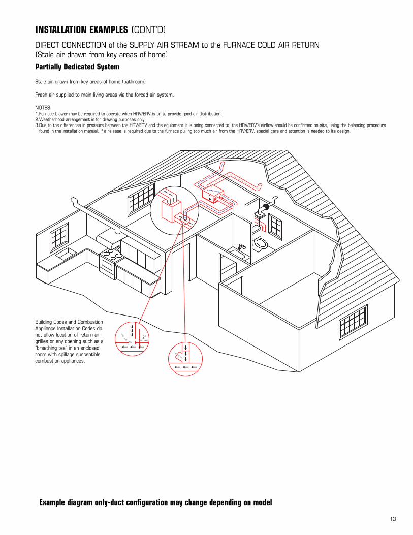
INSTALLATION EXAMPLES (CONT'D)
Example diagram only-duct configuration may change depending on model
Partially Dedicated System
Stale air drawn from key areas of home (bathroom)
Fresh air supplied to main living areas via the forced air system.
NOTES:1.Furnace blower may be required to operate when HRV/ERV is on to provide good air distribution.2.Weatherhood arrangement is for drawing purposes only.3.Due to the differences in pressure between the HRV/ERV and the equipment it is being connected to, the HRV/ERV’s airflow should be confirmed on site, using the balancing procedure
found in the installation manual. If a release is required due to the furnace pulling too much air from the HRV/ERV, special care and attention is needed to its design.
DIRECT CONNECTION of the SUPPLY AIR STREAM to the FURNACE COLD AIR RETURN(Stale air drawn from key areas of home)
Building Codes and CombustionAppliance Installation Codes donot allow location of return airgrilles or any opening such as a“breathing tee” in an enclosedroom with spillage susceptiblecombustion appliances.

14
INSTALLATION EXAMPLES (CONT'D)
DIRECT CONNECTION of both the HRV/ERV SUPPLY AIR STREAM and EXHAUST AIR STREAM to the FURNACE COLD AIR RETURN
Simplified Installation
Option 1(Return/Return Method)
• It is mandatory that the furnace blower run continuously or HRV/ERVoperation be interlocked with the furnace blower
• Check local codes/authority having juris-
diction for acceptance
NOTES:1. Furnace blower is required to run when
HRV/ERV is operating. The furnace should beset to run continuously or interlocked withHRV/ERV.
2. A minimum separation of 39 inches (1m) isrecommended between the two direct connec-tions.
3. The exhaust air connection should be upstreamof the supply air connection to prevent exhaust-ing any fresh air.
4. Weatherhood arrangement is for drawing pur-poses only. 18” (460 mm) above grade mini-mum.
5. Due to the differences in pressure between theHRV/ERV and the equipment it is being con-nected to, the HR/ERV’s airflow should be con-firmed on site, using the balancing procedurefound in the installation manual.
Note: Option 1 is the preferred/rec-ommended method when doing asimplified installation
* Unit isnormallybalancedon HIGHspeedwith furnaceblowerON.
Return Air
1 m(3’-3”) min.recommended
Cool AirReturn
Outdoors
40”Min.
* Ducts connection mayvary depending on model
Example diagram only-duct configuration may change depending on model
15
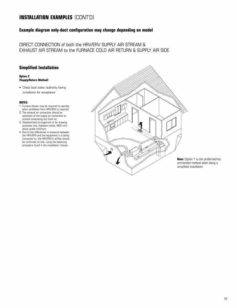
INSTALLATION EXAMPLES (CONT'D)
DIRECT CONNECTION of both the HRV/ERV SUPPLY AIR STREAM &EXHAUST AIR STREAM to the FURNACE COLD AIR RETURN & SUPPLY AIR SIDE
Simplified Installation
Option 2(Supply/Return Method)
• Check local codes /authority having
jurisdiction for acceptance
NOTES:1. Furnace blower may be required to operate
when ventilation from HRV/ERV is required. 2. The exhaust air connection should be
upstream of the supply air connection to prevent exhausting any fresh air.
3. Weatherhood arrangement is for drawingpurposes only. Eighteen inches (460 mm)above grade minimum.
4. Due to the differences in pressure betweenthe HRV/ERV and the equipment it is beingconnected to, the HRV/ERV’s airflow should be confirmed on site, using the balancing procedure found in the installation manual.
Note: Option 1 is the preferred/rec-ommended method when doing asimplified installation
Example diagram only-duct configuration may change depending on model

16
AIR FLOW BALANCING
1 For this flow measuring station, cut the ductand place the flow measuring station betweeneach section of duct. Make sure that the flowmeasuring station’s air direction arrow pointsin the direction of the airflow. Secure the flowmeasuring station with duct tape.
2 Before taking the reading, make sure that themagnehelic gauge is level and at 0. Refer tothe flow measuring station’s chart todetermine your unit’s airflow velocity.
3 Adjust the “Supply Air Out” damper until youreach the desired velocity. Follow the previoussteps to adjust the “Exhaust Air Out” damper,if needed.
B
Measurehere
Measurehere
12”(300 mm)
12”(300 mm)
• To avoid airflowturbulence and incorrectreadings, the airflowvelocity should bemeasured on steelducting a minimum of12” (300 mm) from theunit or elbow and beforeany transition.
AIRFLOW STATION (GRID) METHOD
* Fantech’s superior design and use of EBM motors results in a steep fan curve thatusually does not require balancing. Commissioning the system after installation isrecommended which include confirming the proper operation of the system and howit interacts with other components within the home.

17
MAINTENANCE
The filters (2) need to be checked andcleaned every three months or whenthey appear dirty. Wash in warmsudsy water (mild detergent) or use asoft brush vacuum. The filters shouldbe replaced when they can no longerbe cleaned properly.
PRACTICALTIPS• To prevent electrical shock, check
that the unit is unplugged beforedoing any repairs or maintenance.
• A yearly inspection is recom-mended to ensure the efficiencyand trouble-free use of your sys-tem. Run through the system and verify the different operatingmodes.
HEAT RECOVERY CORE (SH704 & VH704 ONLY)
FILTERS
The motor - The motors are factorybalanced and lubricated for life.They require no maintenance.
The unit - The inside of the unitshould be vacuumed yearly. Becareful not to damage any of themechanical components and elec-trical connections.
Outside hoods - The outside hoodsneed to be checked every season tomake sure there are no leaves orinsects blocking the airflow. Checkregularly that there are no pollu-tants near the intake hood. Makesure they are clear of any snowaccumulation during the wintermonths.
Clean Core and Filters Every 3-6 Months. Unplug unit before doing any repairs or maintenance
a) Open access door.b) Carefully grip handle of core and pull out.
Core will slide out of the channel.c) Once removed from the cabinet remove filters.d) Wash core in warm soapy water (do not use
dishwasher).
e) Install clean core by:a) First mounting the bottom flange of the core guide into the
bottom channel approximately 1/4” (6mm).b) Mount the left or right side flange of the core guide approx-
imately 1/4 “ (6mm) followed by the other side.c) Mount the top flange of the core guide into the top channel
approximately 1/4” (6mm).d) With all four corners in place and the core straight and
even, push hard in the center of the core until the corestops on the back of the cabinet.
f) Install the clean filters.
CAUTION MAKE SURE UNIT IS UNPLUGGED BEFORE ATTEMPTING ANY MAINTENANCE WORK
The following components should also be inspected regularly and well maintained.
NOTE: Some products may not be exactly as illustrated in Installation, Operation and Maintenance manual.
The heat recovery core needs to be checked and cleaned every six months. The core can be cleaned using a mild soap andwater. Rinse thoroughly. Handle with care. Hot water and a strong detergent will damage the heat recovery core. The drain pan and drain line - Units with drain lines should have their line and connection checked regularly.
Filters need to be checked regularly
ENERGY RECOVERY CORE (SE704)
Clean Core and Filters Every 3-6 Months. Unplug unit before doing any repairs or maintenance
a) Open access door.b) Carefully grip handle of core and pull out.
Core will slide out of the channel.c) Once removed from the cabinet remove filters.d) Vacuum core to sligtly remove dirt away.
e) Install clean core by:a) First mounting the bottom flange of the core guide into the
bottom channel approximately 1/4” (6mm).b) Mount the left or right side flange of the core guide approx-
imately 1/4 “ (6mm) followed by the other side.c) Mount the top flange of the core guide into the top channel
approximately 1/4” (6mm).d) With all four corners in place and the core straight and
even, push hard in the center of the core until the corestops on the back of the cabinet.
f) Install the clean filters.
The energy recovery core needs to be checked and cleaned every six months. DO NOT wash this core, instead use a vacuum to lightly draw dirt away from the core.

18
TROUBLESHOOTING
SolutionsCausesProblem
Insufficient water vapor generated
Sudden increase in humidity by cooking orbathing
Sudden change in temperature
Storing too much wood for heating
Dryer vent exhaust is inside home
Poor air circulating near windows
HRV not operating (during winter)
Poor air circulating near windows
Air is too dry
Air is too humid
Persistent condensation on window
Install humidifier
Ventilate at the source of the problem using a HRV or additional fan
Wait until outside temperature stabilizes (winter). Heating will alsoimprove situation.
Store a majority of your wood outside. Even dried, a cord of wood con-tains more than 20 gallons of water.
Arrange outside vent for dryer.
Open curtains or blinds. Bay or bow windows may require mechanicalmethod.
Check power to the unit
Open curtains or blinds. Bay or bow windows may require mechanicalmethod.
-Clean exterior hoods or vents-Remove and clean filter-Remove and clean core-Check and open grilles-Have electrician check supply voltage at house-Check duct installation
-Locate the grilles high on the walls or under the baseboards, installceiling mounted diffuser or grilles so as not to directly spill the supplyair on the occupant (eg. Over a sofa)
-Use superior grilles such as Fantech CG grille A small duct heater(1kw) could be used to temper the supply air
-Placement of furniture or closed doors is restricting the movement ofair in the home
-If supply air is ducted into furnace return, the furnace fan may need torun continuously to distribute ventilation air comfortably
-Note: minimal frost build-up is expected on cores before unit initiatesdefrost cycle functions
-Have HVAC contractor balance the HRV/ERV
-Install duct heater
-Tape and seal all joints-Tape any holes or tears made in the outer duct covering -Ensure that the vapor barrier is completely sealed.
-1/4” (6mm) mesh on the outside hoodsis plugged
-Filters plugged-Core obstructed -House grilles closed or blocked-Dampers are closed (if installed)-Poor power supply at site-Ductwork is restricting HRV/ERV
Poor Air Flows
-Poor location of supply grilles, the airflowmay irritate the occupant(s)
-Outdoor temperature extremely cold
Supply air feels cold
-HRV/ERV air flows are improperly balanced
-Malfunction of the HRV/ERV defrost system
-Outdoor temp. extremely cold
HRV / ERV and / orDucts Frosting up
-Incomplete vapor barrier around insulated duct
-A hole or tear in outer duct covering
Condensation or IceBuild Up in InsulatedDuct to the Outside

19
ELECTRICAL CONNECTIONS
PC
BLACK
WHITE
COM NO
SW CAP2
BLUE
EXHBLACK
FAN2
BROWN
CAP1
SUPBLACK
FAN1BLUE
BROWN
GREEN
BLUE
BLUE
WHT/RED
WHT/BLK
RED
BLACK
SYMBOL DECRIPTION SYMBOL DESCRIPTION
PROJECT
DRAWN BY
NOTE :
SHEET
DATE
50 Kanalflakt Way
Fax/Tcpr:(506) 743-9600Tel:/Tel: (506) 743-9500
Bouctouche, NB, Canada E4S-3M5
The duplication and usage of this document or the contents thereof, without proper authorization is strictly prohibited. Contravention will be prosecuted.La duplication et l utilisation de ce document ou de son contenu sans autorisation est strictement interdite. Toute contravention sera poursuivie.
APPROVED BY: DRAWING NO./ ITEM NO.
ITEM NO.
DESCRIPTION
REVISIONS DATE
PRIMARY VOLTAGE:
AMPERAGE:
POWER CONSUMPTION: 41 WATTS
0.35 AMPS
120V, 60HZ, 1PH
DOOR SWITCH (#410152)
CAPACITOR 2UF, 450V, REC (#411007)
R2E133-BH94, 115V, 60HZ, 20W, 2UF (#410031)FAN1,2
CAP1,2
SW
POWER CORD, SJTW, 18/3, BLACK (#410055) P.C.
Fantech
WI\403136
SHEET 1 OF 1
DANIEL DESJARDINS
403136
16-09-05
Wiring Diag,SE704
SE704
SH704 & VH704
SE704

20
Fantech, reserves the right to modify, at any time and withoutnotice, any or all of its products’ features, designs, components andspecifications to maintain their technological leadership position.
Item #: 403165Rev Date: 120805
United States1712 Northgate Blvd.,
Sarasota, FL. 34234
Phone: 800.747.1762; 941.309.6000
Fax: 800.487.9915; 941.309.6099
www.fantech.net; [email protected]
Canada50 Kanalflakt Way,
Bouctouche, NB E4S 3M5
Phone: 800.565.3548; 506.743.9500
Fax: 877.747.8116; 506.743.9600
www.fantech.ca; [email protected]