important notice - haiyang.co.krhaiyang.co.kr/smart780_f.pdf · important notice pictorials this...
TRANSCRIPT
- 1 -
Important Notice
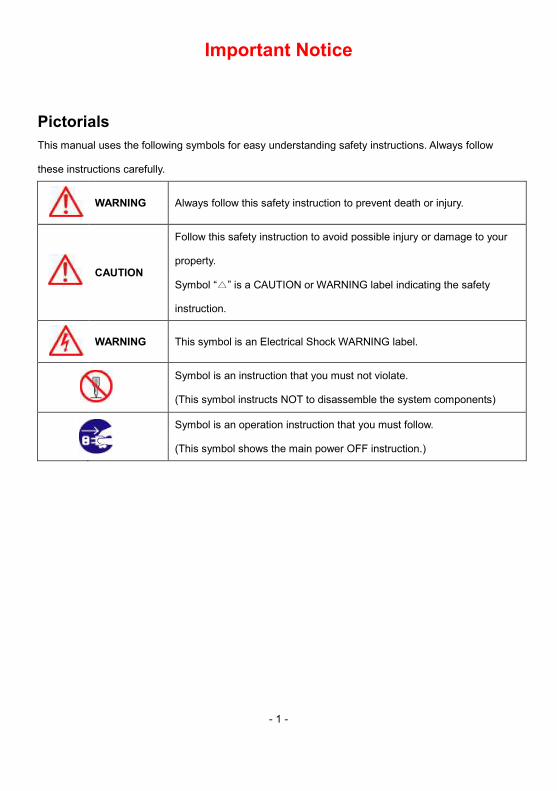
Pictorials This manual uses the following symbols for easy understanding safety instructions. Always follow
these instructions carefully.
WARNING Always follow this safety instruction to prevent death or injury.
CAUTION
Follow this safety instruction to avoid possible injury or damage to your
property.
Symbol “△” is a CAUTION or WARNING label indicating the safety
instruction.
WARNING This symbol is an Electrical Shock WARNING label.
Symbol is an instruction that you must not violate.
(This symbol instructs NOT to disassemble the system components)
Symbol is an operation instruction that you must follow.
(This symbol shows the main power OFF instruction.)
- 2 -
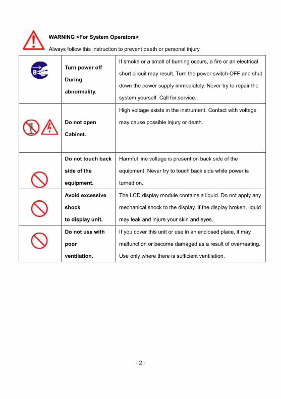
WARNING <For System Operators>
Always follow this instruction to prevent death or personal injury.
Turn power off
During
abnormality.
If smoke or a small of burning occurs, a fire or an electrical
short circuit may result. Turn the power switch OFF and shut
down the power supply immediately. Never try to repair the
system yourself. Call for service.
Do not open
Cabinet.
High voltage exists in the instrument. Contact with voltage
may cause possible injury or death.
Do not touch back
side of the
equipment.
Harmful line voltage is present on back side of the
equipment. Never try to touch back side while power is
turned on.
Avoid excessive
shock
to display unit.
The LCD display module contains a liquid. Do not apply any
mechanical shock to the display. If the display broken, liquid
may leak and injure your skin and eyes.
Do not use with
poor
ventilation.
If you cover this unit or use in an enclosed place, it may
malfunction or become damaged as a result of overheating.
Use only where there is sufficient ventilation.
- 3 -
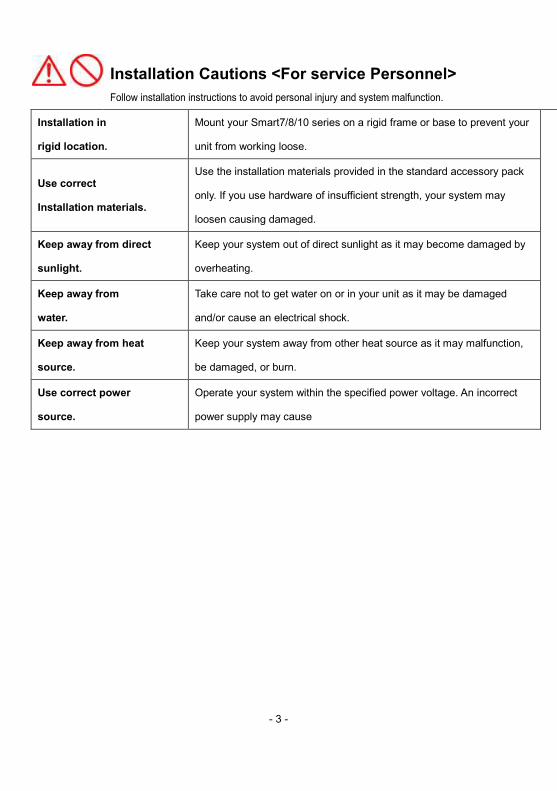
Installation Cautions <For service Personnel> Follow installation instructions to avoid personal injury and system malfunction.
Installation in
rigid location.
Mount your Smart7/8/10 series on a rigid frame or base to prevent your
unit from working loose.
Use correct
Installation materials.
Use the installation materials provided in the standard accessory pack
only. If you use hardware of insufficient strength, your system may
loosen causing damaged.
Keep away from direct
sunlight.
Keep your system out of direct sunlight as it may become damaged by
overheating.
Keep away from
water.
Take care not to get water on or in your unit as it may be damaged
and/or cause an electrical shock.
Keep away from heat
source.
Keep your system away from other heat source as it may malfunction,
be damaged, or burn.
Use correct power
source.
Operate your system within the specified power voltage. An incorrect
power supply may cause
- 4 -
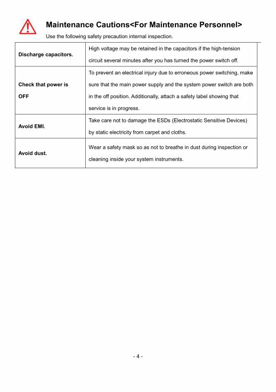
Maintenance Cautions<For Maintenance Personnel> Use the following safety precaution internal inspection.
Discharge capacitors. High voltage may be retained in the capacitors if the high-tension
circuit several minutes after you has turned the power switch off.
Check that power is
OFF
To prevent an electrical injury due to erroneous power switching, make
sure that the main power supply and the system power switch are both
in the off position. Additionally, attach a safety label showing that
service is in progress.
Avoid EMI. Take care not to damage the ESDs (Electrostatic Sensitive Devices)
by static electricity from carpet and cloths.
Avoid dust. Wear a safety mask so as not to breathe in dust during inspection or
cleaning inside your system instruments.
- 5 -
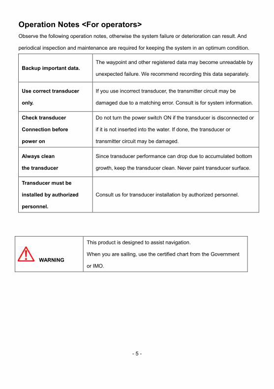
Operation Notes <For operators> Observe the following operation notes, otherwise the system failure or deterioration can result. And
periodical inspection and maintenance are required for keeping the system in an optimum condition.
Backup important data. The waypoint and other registered data may become unreadable by
unexpected failure. We recommend recording this data separately.
Use correct transducer
only.
If you use incorrect transducer, the transmitter circuit may be
damaged due to a matching error. Consult is for system information.
Check transducer
Connection before
power on
Do not turn the power switch ON if the transducer is disconnected or
if it is not inserted into the water. If done, the transducer or
transmitter circuit may be damaged.
Always clean
the transducer
Since transducer performance can drop due to accumulated bottom
growth, keep the transducer clean. Never paint transducer surface.
Transducer must be
installed by authorized
personnel.
Consult us for transducer installation by authorized personnel.
WARNING
This product is designed to assist navigation.
When you are sailing, use the certified chart from the Government
or IMO.

- 6 -
- 7 -
Smart7/8/10 System
Welcome
Smart7/8/10 series opens a new chapter of performance and integration in vessel navigation system
display and management. Whether you are a Cruiser or Sport fisherman or both, Smart7/8/10 gives
you the information you need.
CAUTION
Smart7/8/10 series is Color LCD Charting Systems employs the latest in proven technology to provide
accurate navigation information. The Plotter functions of Smart7/8/10 are totally dependent upon the
capability of the navigation source to provide accurate position information. This device is only an aid
to navigation. It should be used in conjunction with all other navigation accuracy. For safety, always
resolve any uncertainty before continuing navigation.
CAUTION
The performance of LCD displays are degraded by continuous direct exposure to ultraviolet rays.
Locate your Smart7/8/10 series Display away from direct sunlight. When not in use. Keep the display
covered.
DISPLAY BREAKAGE WARNING The LCD display module contains a liquid. If the display is broken and the liquid contacts your skin,
wash it off immediately in running water for 15 minutes. If the liquid contacts your eyes, immediately
flush your eyes with running water for 15 minutes. Contact a physician if any abnormal symptom is
experienced.
- 8 -
Smart7/8/10 Series System
Welcome
The Smart7/8/10 series opens a new chapter of performance and integration in vessel navigation
system display and management. Whether you are a Cruiser or Sport fisherman or both, Smart7/8/10
gives you the information you need.
CAUTION The Smart7/8/10 series employs the latest in proven technology to provide accurate navigation
information. The Plotter functions of Smart7/8/10 series are totally dependent upon the capability of
the navigation source to provide accurate position information. This device is only an aid to navigation.
It should be used in conjunction with all other navigation accuracy. For safety, always resolve any
uncertainty before continuing navigation.
There is no direct relationship between the color of water areas and their depth. The navigator shall
always query the area for depth information and use the official paper chart.
CAUTION The performance of LCD displays is degraded by continuous direct exposure to ultraviolet rays. Locate
your Smart7/8/10 series Display away from direct sunlight. When not in use. Keep the display covered.
- 9 -
Smart7/8/10 Series System
DISPLAY BREAKAGE WARNING
The LCD display module contains a liquid. If the display is broken and the liquid contacts your skin,
wash it off immediately in running water for 15 minutes. If the liquid contacts your eyes,
immediately flush your eyes with running water for 15 minutes. Contact a physician if any abnormal
symptom is experienced.
INDICATION NOTICE
*: It is important or warning notice on front of article [ ]: Keyboard.

- 10 -
- 11 -
Getting Started
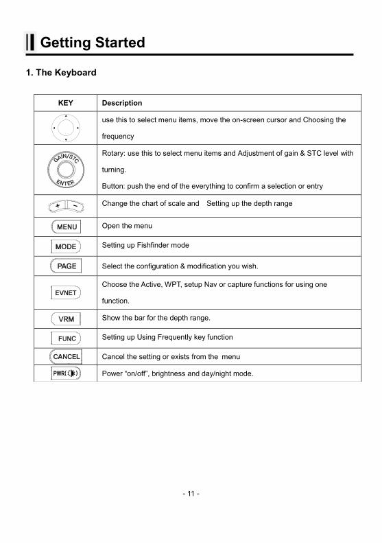
1. The Keyboard
KEY Description
use this to select menu items, move the on-screen cursor and Choosing the
frequency
Rotary: use this to select menu items and Adjustment of gain & STC level with
turning.
Button: push the end of the everything to confirm a selection or entry
Change the chart of scale and Setting up the depth range
Open the menu
Setting up Fishfinder mode
Select the configuration & modification you wish.
Choose the Active, WPT, setup Nav or capture functions for using one
function.
Show the bar for the depth range.
Setting up Using Frequently key function
Cancel the setting or exists from the menu
Power “on/off”, brightness and day/night mode.
- 12 -
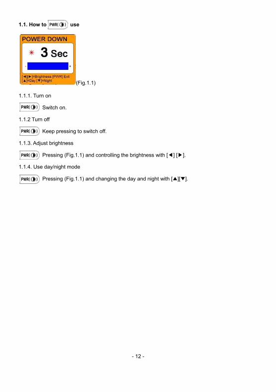
1.1. How to use
(Fig.1.1)
1.1.1. Turn on
Switch on.
1.1.2 Turn off
Keep pressing to switch off.
1.1.3. Adjust brightness
Pressing (Fig.1.1) and controlling the brightness with [◀] [▶].
1.1.4. Use day/night mode
Pressing (Fig.1.1) and changing the day and night with [▲][▼].
- 13 -
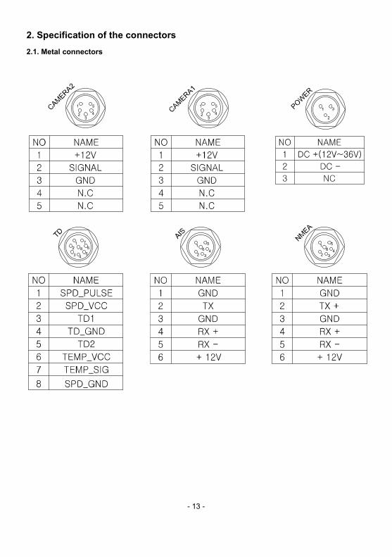
2. Specification of the connectors 2.1. Metal connectors
- 14 -
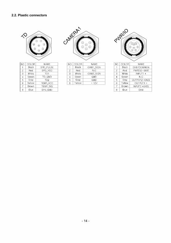
2.2. Plastic connectors
- 15 -
3. Screen Overview
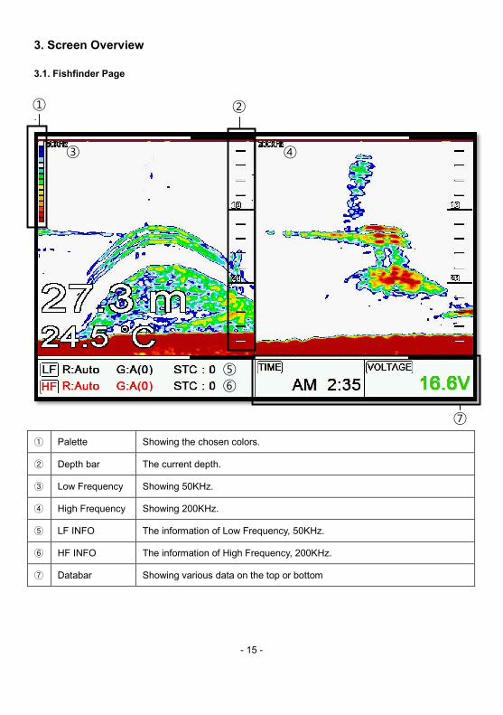
3.1. Fishfinder Page
.
① Palette Showing the chosen colors.
② Depth bar The current depth.
③ Low Frequency Showing 50KHz.
④ High Frequency Showing 200KHz.
⑤ LF INFO The information of Low Frequency, 50KHz.
⑥ HF INFO The information of High Frequency, 200KHz.
⑦ Databar Showing various data on the top or bottom
③ ④
⑤
⑥
① ②
⑦
- 16 -
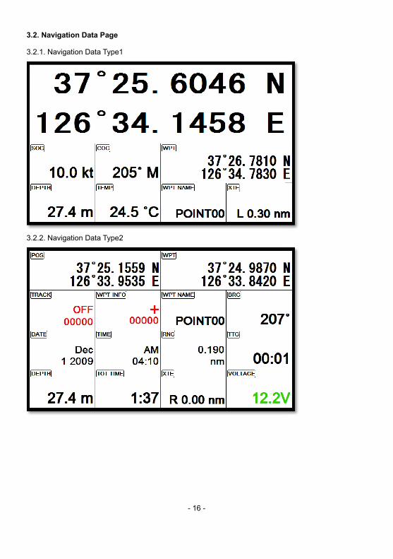
3.2. Navigation Data Page
3.2.1. Navigation Data Type1
3.2.2. Navigation Data Type2
- 17 -
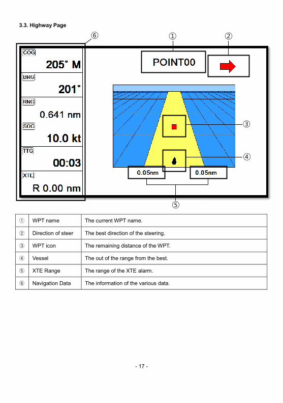
3.3. Highway Page
① WPT name The current WPT name.
② Direction of steer The best direction of the steering.
③ WPT icon The remaining distance of the WPT.
④ Vessel The out of the range from the best.
⑤ XTE Range The range of the XTE alarm.
⑥ Navigation Data The information of the various data.
① ⑥
⑤
②
③
④
- 18 -
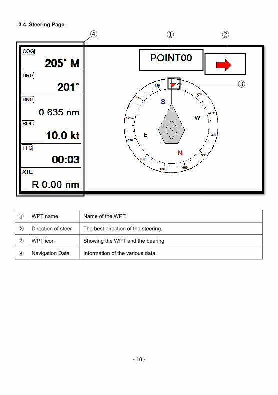
3.4. Steering Page
① WPT name Name of the WPT.
② Direction of steer The best direction of the steering.
③ WPT icon Showing the WPT and the bearing
④ Navigation Data Information of the various data.
① ④
②
③
- 19 -
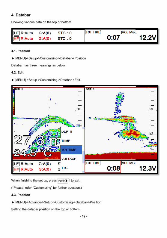
4. Databar Showing various data on the top or bottom.
4.1. Position
▶[MENU]->Setup->Customizing->Databar->Position
Databar has three meanings as below.
4.2. Edit
▶[MENU]->Setup->Customizing->Databar->Edit
When finishing the set up, press to exit.
(*Please, refer “Customizing” for further question.)
4.3. Position
▶[MENU]->Advance->Setup->Customizing->Databar->Position
Setting the databar position on the top or bottom.
- 20 -
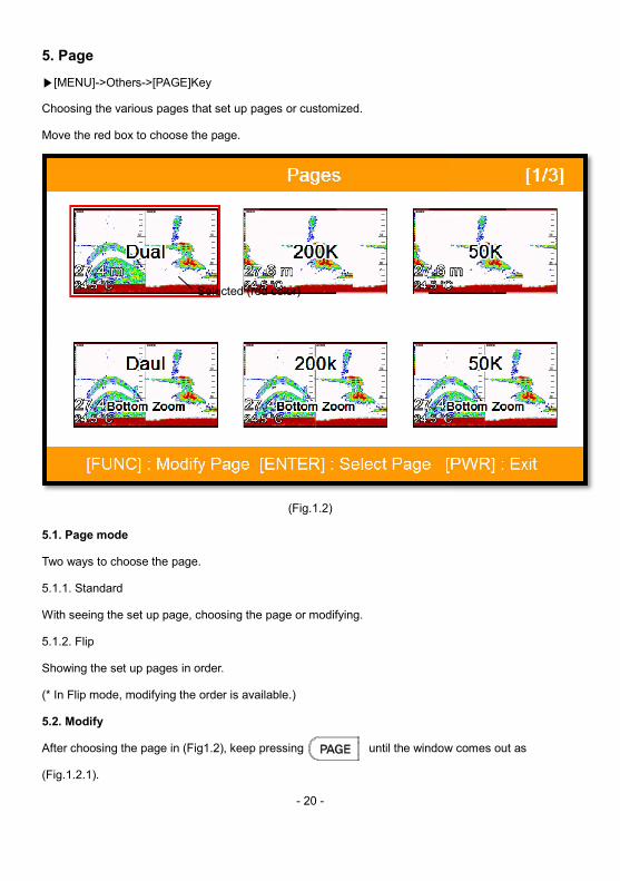
5. Page
▶[MENU]->Others->[PAGE]Key
Choosing the various pages that set up pages or customized.
Move the red box to choose the page.
(Fig.1.2)
5.1. Page mode
Two ways to choose the page.
5.1.1. Standard
With seeing the set up page, choosing the page or modifying.
5.1.2. Flip
Showing the set up pages in order.
(* In Flip mode, modifying the order is available.)
5.2. Modify
After choosing the page in (Fig1.2), keep pressing until the window comes out as
(Fig.1.2.1).
Selected (red color)
choosing the page in (Fig1.2), keep pressing until the window comes out as
- 21 -
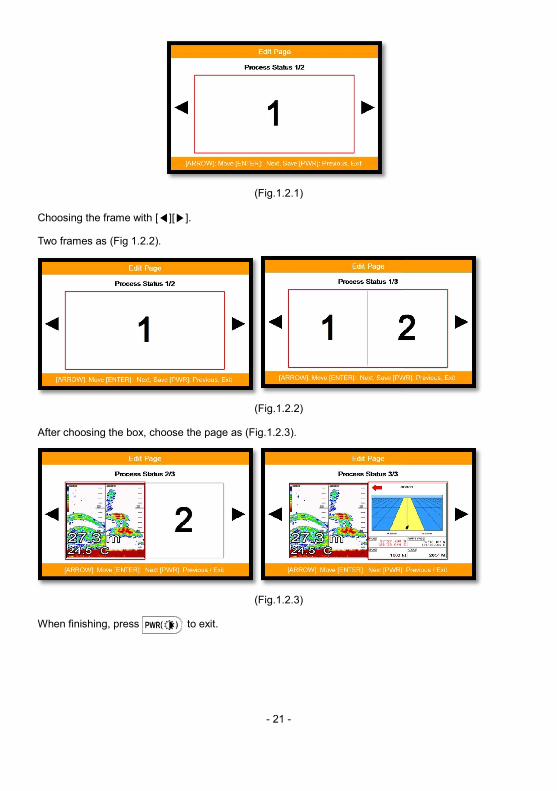
(Fig.1.2.1)
Choosing the frame with [◀][▶].
Two frames as (Fig 1.2.2).
(Fig.1.2.2)
After choosing the box, choose the page as (Fig.1.2.3).
(Fig.1.2.3)
When finishing, press to exit.
- 22 -
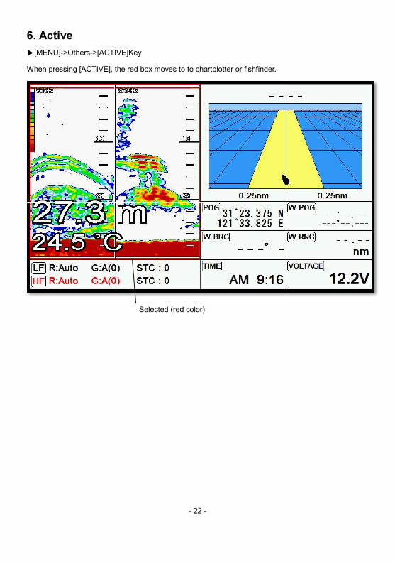
6. Active
▶[MENU]->Others->[ACTIVE]Key
When pressing [ACTIVE], the red box moves to to chartplotter or fishfinder.
Selected (red color)
- 23 -
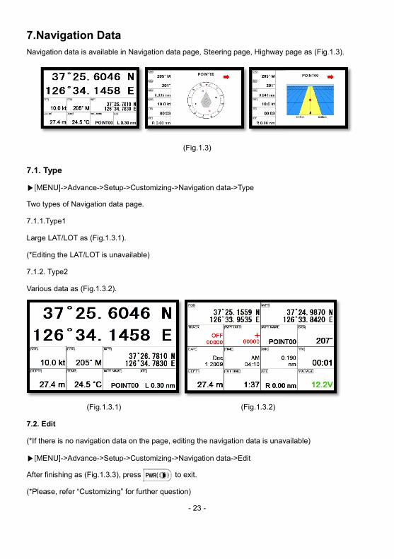
7.Navigation Data
Navigation data is available in Navigation data page, Steering page, Highway page
(Fig.1.3)
7.1. Type
▶[MENU]->Advance->Setup->Customizing->Navigation data->Type
Two types of Navigation data page.
7.1.1.Type1
Large LAT/LOT as (Fig.1.3.1).
(*Editing the LAT/LOT is unavailable)
7.1.2. Type2
Various data as (Fig.1.3.2).
(Fig.1.3.1) (Fig.1.3.2)
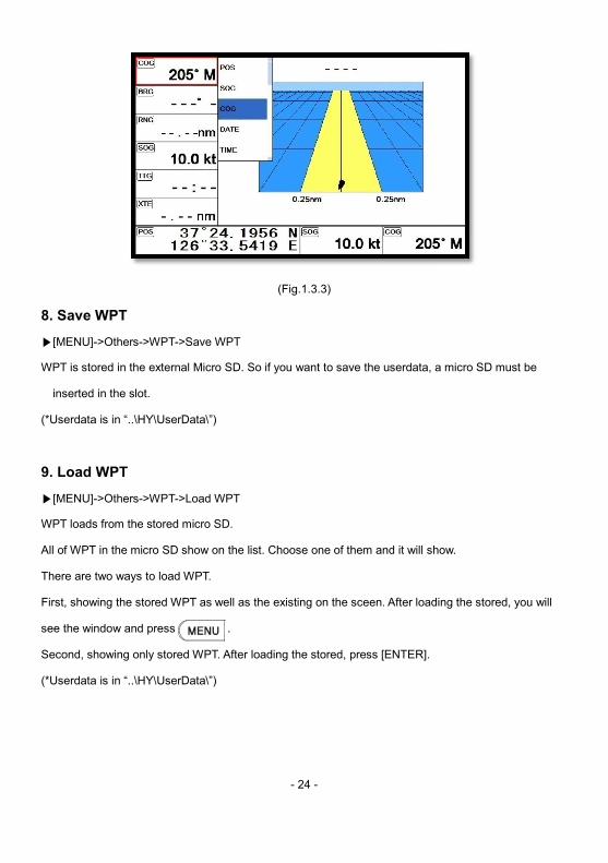
7.2. Edit
(*If there is no navigation data on the page, editing the navigation data is unavailable
▶[MENU]->Advance->Setup->Customizing->Navigation data->Edit
After finishing as (Fig.1.3.3), press to exit.
(*Please, refer “Customizing” for further question)
ighway page as (Fig.1.3).
is unavailable)
- 24 -
(Fig.1.3.3)
8. Save WPT
▶[MENU]->Others->WPT->Save WPT
WPT is stored in the external Micro SD. So if you want to save the userdata, a micro SD must be
inserted in the slot.
(*Userdata is in “..\HY\UserData\”)
9. Load WPT
▶[MENU]->Others->WPT->Load WPT
WPT loads from the stored micro SD.
All of WPT in the micro SD show on the list. Choose one of them and it will show.
There are two ways to load WPT.
First, showing the stored WPT as well as the existing on the sceen. After loading the stored, you will
see the window and press .
Second, showing only stored WPT. After loading the stored, press [ENTER].
(*Userdata is in “..\HY\UserData\”)
, a micro SD must be
All of WPT in the micro SD show on the list. Choose one of them and it will show.
the stored WPT as well as the existing on the sceen. After loading the stored, you will
- 25 -
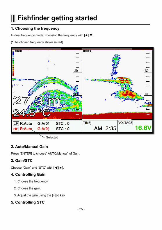
Fishfinder getting started 1. Choosing the frequency In dual frequency mode, choosing the frequency with [▲][▼].
(*The chosen frequency shows in red)
2. Auto/Manual Gain Press [ENTER] to choose” AUTO/Manual” of Gain.
3. Gain/STC
Choose “Gain” and “STC” with [◀][▶].
4. Controlling Gain 1. Choose the frequency.
2. Choose the gain.
3. Adjust the gain using the [+] [-] key.
5. Controlling STC
Selected
- 26 -
1. Choose the frequency.
2. Choose the STC.
3. Adjust the STC using the [+] [-] key.
6. Mode ▶[MENU]->Mode
Four kinds in Fishfinder.
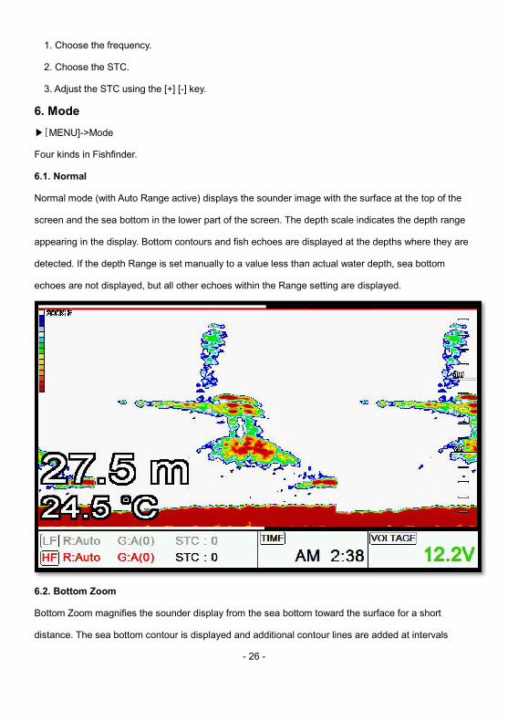
6.1. Normal
Normal mode (with Auto Range active) displays the sounder image with the surface at the top of the
screen and the sea bottom in the lower part of the screen. The depth scale indicates the depth range
appearing in the display. Bottom contours and fish echoes are displayed at the depths where they are
detected. If the depth Range is set manually to a value less than actual water depth, sea bottom
echoes are not displayed, but all other echoes within the Range setting are displayed.
6.2. Bottom Zoom
Bottom Zoom magnifies the sounder display from the sea bottom toward the surface for a short
distance. The sea bottom contour is displayed and additional contour lines are added at intervals
Normal mode (with Auto Range active) displays the sounder image with the surface at the top of the
screen and the sea bottom in the lower part of the screen. The depth scale indicates the depth range
display. Bottom contours and fish echoes are displayed at the depths where they are
detected. If the depth Range is set manually to a value less than actual water depth, sea bottom
e displayed.
Bottom Zoom magnifies the sounder display from the sea bottom toward the surface for a short
distance. The sea bottom contour is displayed and additional contour lines are added at intervals
- 27 -
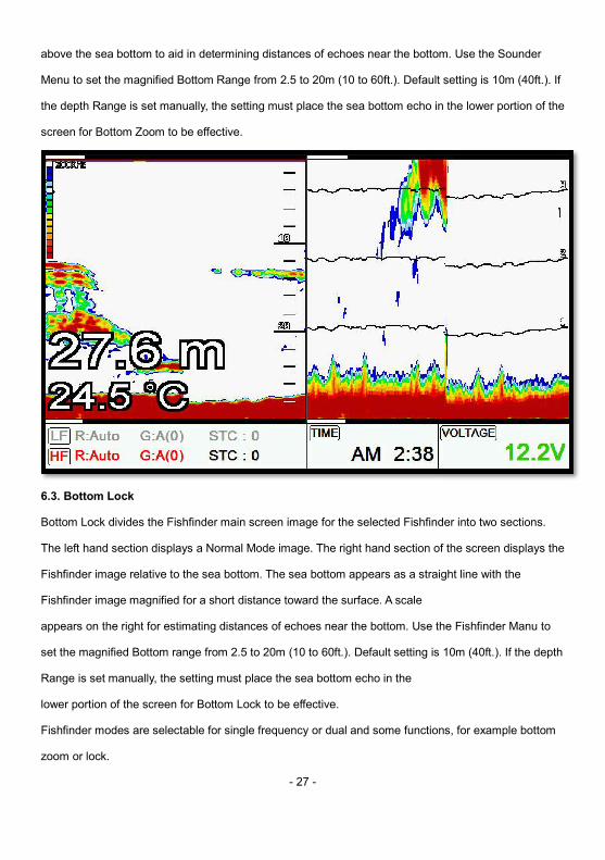
above the sea bottom to aid in determining distances of echoes near the bottom. Use the Sounder
Menu to set the magnified Bottom Range from 2.5 to 20m (10 to 60ft.). Default setting is 10m (40ft.). If
the depth Range is set manually, the setting must place the sea bottom echo in the lower portion of the
screen for Bottom Zoom to be effective.
6.3. Bottom Lock
Bottom Lock divides the Fishfinder main screen image for the selected Fishfinder into two sections.
The left hand section displays a Normal Mode image. The right hand section of the screen displays the
Fishfinder image relative to the sea bottom. The sea bottom appears as a straight line with the
Fishfinder image magnified for a short distance toward the surface. A scale
appears on the right for estimating distances of echoes near the bottom. Use the Fishfinder Manu to
set the magnified Bottom range from 2.5 to 20m (10 to 60ft.). Default setting is 10m (40ft.). If the depth
Range is set manually, the setting must place the sea bottom echo in the
lower portion of the screen for Bottom Lock to be effective.
Fishfinder modes are selectable for single frequency or dual and some functions, for example bottom
zoom or lock.
above the sea bottom to aid in determining distances of echoes near the bottom. Use the Sounder
Menu to set the magnified Bottom Range from 2.5 to 20m (10 to 60ft.). Default setting is 10m (40ft.). If
the sea bottom echo in the lower portion of the
Bottom Lock divides the Fishfinder main screen image for the selected Fishfinder into two sections.
ge. The right hand section of the screen displays the
Fishfinder image relative to the sea bottom. The sea bottom appears as a straight line with the
mating distances of echoes near the bottom. Use the Fishfinder Manu to
set the magnified Bottom range from 2.5 to 20m (10 to 60ft.). Default setting is 10m (40ft.). If the depth
Fishfinder modes are selectable for single frequency or dual and some functions, for example bottom
- 28 -
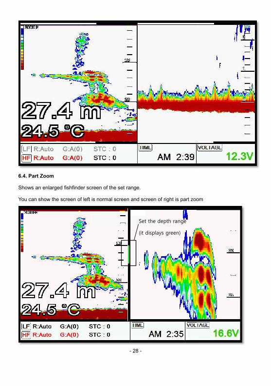
6.4. Part Zoom
Shows an enlarged fishfinder screen of the set range.
You can show the screen of left is normal screen and screen of right is part zoom
Set the depth range
(it displays green)
the screen of left is normal screen and screen of right is part zoom
- 29 -
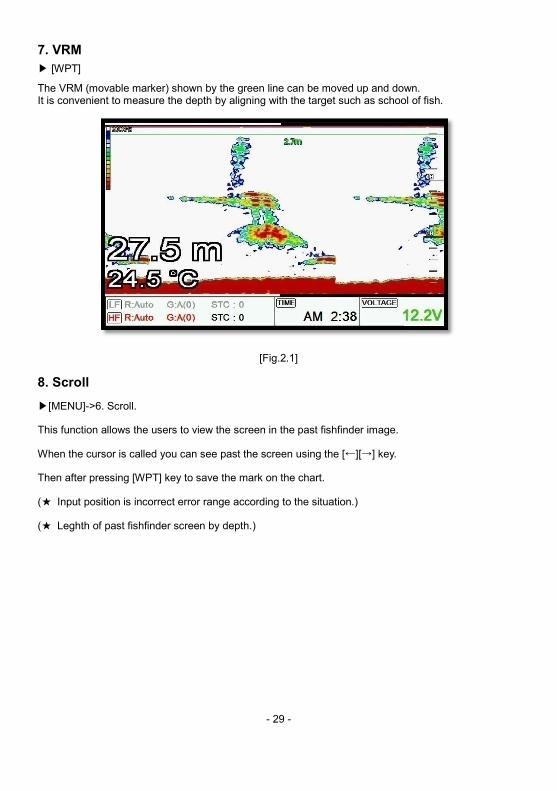
7. VRM ▶ [WPT]
The VRM (movable marker) shown by the green line can be moved up and down.It is convenient to measure the depth by aligning with the target such as school of fish.
[Fig.2.1]
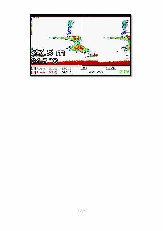
8. Scroll ▶[MENU]->6. Scroll.
This function allows the users to view the screen in the past fishfinder image.
When the cursor is called you can see past the screen using the [←][→] key.
Then after pressing [WPT] key to save the mark on the chart.
(★ Input position is incorrect error range according to the situation.)
(★ Leghth of past fishfinder screen by depth.)
The VRM (movable marker) shown by the green line can be moved up and down. with the target such as school of fish.
- 30 -
- 31 -
Operation 1. Deep Depth Range Smart7/8/10 selects the best condition for measuring the depth automatically in the environment of the
sea.
☞( The default setting is Auto.)
2. Shift A user selects this function to see more detailed bottom of the sea. When you turn up the shift, the
range of Fish finder shall go up from the shift range. For example, if you raise 5m of shift at 20m range,
the surface shall start 5m and the bottom range shall be 25m.
☞( The default setting is 0m.)
3. Display 3.1. A-scope
A-scope shows the research under the water by a scope to see the environment under the water.
☞( The default setting is OFF.)
3.2. Image Speed:
Select the speed of Fish finder image from 4X until 1/32X.
☞( The default setting is 1X.)
3.3. White Line
It is necessary to research a detailed fish on the bottom or a seaweed under the sea. The color of the
bottom changes into white or black to see the bottom easier than red.
☞( The default setting is OFF.)
3.4. Zoom Range
3.4.1. Bottom Zoom Range
Select the range of the bottom zoom or lock. It is necessary to modify the bottom.
(☞ The default setting is 10m.)
3.4.2. Part Zoom
You can set the depth range when using the part zoom.
- 32 -
3.5.Depth
3.5.1. Display
Shown/Hidden the depth range on the screen.
☞( The default setting is shown.)
3.5.2. Font Size
Select the depth range font size on the screen.
☞( The default setting is Large.)
3.6. TEMP
3.6.1. Display
Shown/Hidden the temperature on the screen.
☞( The default setting is shown.)
3.6.2. Font Size
Select the temperature font size on the screen.
☞( The default setting is Large.)
3.7. Frequency Display
3.8. Speed
3.8.1. Display
Shown/Hidden the speed on the screen.
☞( The default setting is hidden.)
3.8.2. Font Size
Select the temperature font size on the screen.
☞( The default setting is Large.)
3.9. Fish
3.9.1. Fish symbol
Fish symbol with sizes and levels show for targets.
(*Fish symbol is only for reference. This could be different from the real.)
3.9.2. Fish size
Setup to display of the size of fish.
- 33 -
☞( The default setting is Off.) 3.10. Image filtering This function is reduction of the noise.
(☞ The default setting is On.)
4. Rejection 4.1. Interference Rejection
When there are another boats around you on sailing, your Fish finder could be disturbed to work. The
step of the function is from off to level 2. The bigger number, the more rejection.
☞( The default setting is OFF.)
4.2. Noise Rejection
Your Fish finder could be disturbed by the engine noise. This function can reject the noise from the
engine or other machinery instruments.
☞( The default setting is OFF.)
4.3. DSTC
This function can reject the noise of surface.
(☞ The default setting is ON.)
5. Color 5.1. Bottom enhance
This function adjusts the colors. Make it upper level, the color becomes darker.
☞( The default setting is OFF.)
5.2. Color Rejection
There are 16 color levels for Fish finder. The color bar is on the left of the Fish finder. If the level is
higher, the color of the bar is deleted one by one.
5.3. Screen Color
Select he back ground color of the Fish finder for your convenience.
6. Scroll You can seek past fishfinder screen.
7. Output Power
- 34 -
Select the output from the installed transducer. Levels are from off to 3. It should be careful about the
depth. If you set high level in a shallow depth, the Fish finder screen turns to red. You see nothing
expect red on the screen.
☞( The default setting is 3.)
8. Alarm 8.1. Depth
8.1.1. Deep Depth Alarm
It alarms when the set deep depth is out of the range.
☞( The default setting is OFF.)
8.1.2. Deep Depth Range
Setup the range of deep depth alarm
☞( The default setting is 0M.)
8.1.3. Shallow Alarm
It alarms when the set shallow depth is out of the range.
☞( The default setting is OFF.)
8.1.4. Shallow Range
Setup the range of shallow depth alarm
☞( The default setting is 0M.)
8.2. TEMP(Temperature)
8.2.1. High alarm
It alarms when the set high temperature is out of the range.
☞( The default setting is OFF.)
8.2.2. High Range
It alarms when the set high temperature is out of the range.
☞( The default setting is 0.)
8.2.3. Low alarm
It alarms when the set low temperature is out of the range.
☞( The default setting is OFF.)
- 35 -
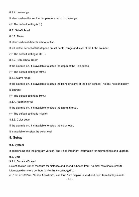
8.2.4. Low range
It alarms when the set low temperature is out of the range.
☞( The default setting is 0.)
8.3. Fish-School
8.3.1. Alarm
It alarms when it detects school of fish.
It will detect school of fish depend on set depth, range and level of the Echo sounder.
☞( The default setting is OFF.)
8.3.2. Fish-school Depth
If the alarm is on, It is available to setup the depth of the Fish-school
☞( The default setting is 10m.)
8.3.3.Alarm range
If the alarm is on, It is available to setup the Range(height) of the Fish-school.(The bar, next of display
is shown)
☞( The default setting is 50m.)
8.3.4. Alarm Interval
If the alarm is on, It is available to setup the alarm interval.
☞( The default setting is middle)
8.3.5. Color Level
If the alarm is on, It is available to setup the color level.
It is available to setup the color level
9. Setup
9.1. System
It contains ID and the program version, and it has important information for maintenance and upgrade.
9.2. Unit 9.2.1. Distance/Speed
Select desired unit of measure for distance and speed. Choose from: nautical mile/knots (nm/kt),
kilometer/kilometers per hour(km/kmh), yard/knot(yd/kt).
cf) 1nm = 1.852km, 1kt /h= 1.852km/h, less than 1nm display in yard and over 1nm display in mile
- 36 -
(☞ The default setting is Nm/Kt.)
9.2.2. Depth
Select desired unit of measure for depth of water. Choose from: meter(M), foot(ft), fathom(fm), Italian
Fathom(Ifm), Japanese fathom(Jfm).
cf) 1m = 3.281ft = 0.549fm = 0.609lfm = 0.660jfm
☞( The default setting is Meter.)
9.2.3. Temperature
Select desired unit of measure for temperature of water. Choose from: Celsius(℃), or Fahrenh eit(℉).
cf) 1℃ = +32℉
9.3. Time/Date 9.3.1. Reference
Available to adjust the collect local time by the UTC time from the GPS.
☞( The default setting is incorrect every the country.)
9.3.2. Time format
Sets you preferred time between 12 hour and 24 hour.
☞( The default setting is 12 hour.)
9.3.3. Date Format
Sets you preferred date among YY-MM-DD, MM-DD-YY or DD-MM-YY.
☞( The default setting is YY-MM-DD.)
9.3.4. Month format
Setup the character of month(Ex: 1, 2, 3…or JAN, FEB, MAR…)
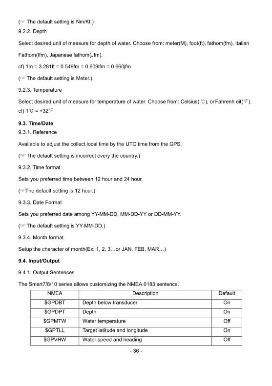
9.4. Input/Output
9.4.1. Output Sentences
The Smart7/8/10 series allows customizing the NMEA.0183 sentence.
NMEA Description Default
$GPDBT Depth below transducer On
$GPDPT Depth On
$GPMTW Water temperature Off
$GPTLL Target latitude and longitude On
$GPVHW Water speed and heading Off
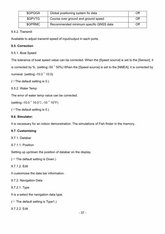
- 37 -
$GPGGA Global positioning system fix data Off
$GPVTG Course over ground and ground speed Off
$GPRMC Recommended minimum specific GNSS data Off
9.4.2. Transmit
Available to adjust transmit speed of input/output in each ports.
9.5. Correction
9.5.1. Boat Speed
The tolerance of boat speed value can be corrected. When the [Speed source] is set to the [Sensor], it
is corrected by %. (setting:-50~50%) When the [Speed source] is set to the [NMEA], it is corrected by
numeral. (setting:-10.0~10.0)
☞( The default setting is 0.)
9.5.2. Water Temp
The error of water temp value can be corrected.
(setting:-10.0~10.0℃,-10~10°F)
☞( The default setting is 0.)
9.6. Simulator:
It is necessary for an indoor demonstration. The simulations of Fish finder in the memory..
9.7. Customizing
9.7.1. Databar
9.7.1.1. Position
Setting up up/down the position of databar on the display.
☞( The default setting is Down.)
9.7.1.2. Edit
It customizes the data bar information.
9.7.2. Navigation Data
9.7.2.1. Type
It is a select the navigation data type.
☞( The default setting is Type1.)
9.7.2.2. Edit
- 38 -
It customizes the Navigation data section except activated the echo sounder section.
9.7.3. Page mode
It is a select the page mode.
- Standard: Choosing Page and customizing is available.
- Flip: Showing the chosen pages in order.
☞( The default setting is Standard.) 9.8. Language:
Select the language. 9.9. Initialization
9.9.1. User Initialization
The stored setting is initialized in the user setting.
9.9.2. Setup Initialization
reset without deleting user data.
9.9.3. Factory Initialization
returning to the initial system from the releasing of factory.
(*All user data will be deleted) 9.10. Others
9.10.1. Speed source
Switch the Sensor/NMEA.
- InsideSensor: Use the built-in speed meter for sensor.
- NMEA: Use the external input value for NMEA.
☞( The default setting is NEMA.)
9.10.2. TD setup
Choosing the frequency of the TD.
9.10.3. Buzzer
It is can be sound on/off.
☞( The default setting is on.)
9.10.4. Remote control settings
9.10.4.1. Remote control
- 39 -
You can set whether to use the remote control.
9.10.4.2. Remote control register
The remote control allows you to register your product.
9.10.4.3. Remote control unregister
This is used to unregister the remote control.
10. Others 10.1. Key Setup
It is available to set up [FUNK] key and [EVENT] key on the JFC.7050.
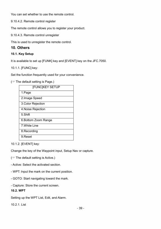
10.1.1. [FUNC] key:
Set the function frequently used for your convenience.
☞( The default setting is Page.)
[FUNC]KEY SETUP
1.Page
2.Image Speed
3.Color Rejection
4.Noise Rejection
5.Shift
6.Bottom Zoom Range
7.White Line
8.Recording
9.Reset
10.1.2. [EVENT] key:
Change the key of the Waypoint input, Setup Nav or capture.
☞( The default setting is Active.)
- Active: Select the activated section.
- WPT: Input the mark on the current position.
- GOTO: Start navigating toward the mark.
- Capture: Store the current screen. 10.2. WPT
Setting up the WPT List, Edit, and Alarm.
10.2.1. List
- 40 -
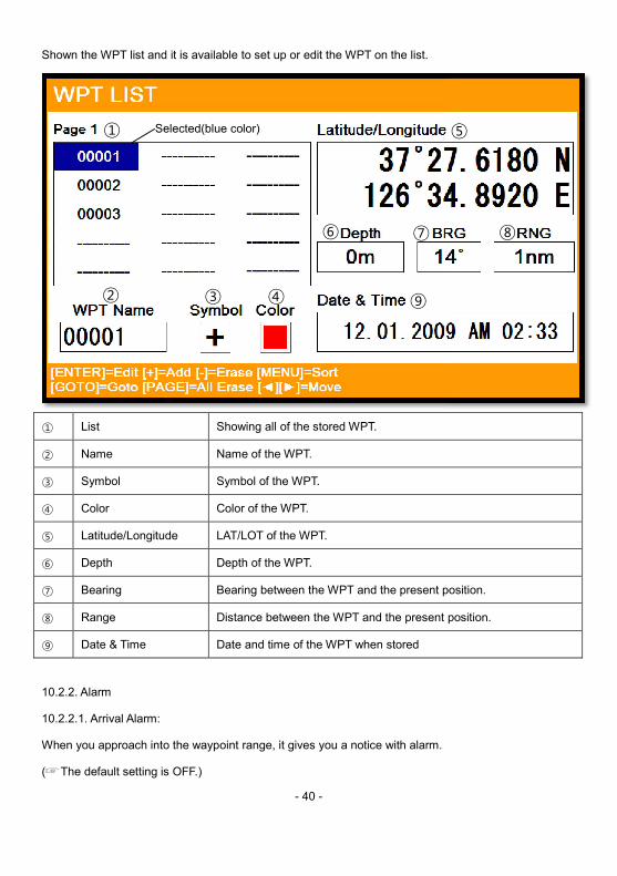
Shown the WPT list and it is available to set up or edit the WPT on the list.
① List Showing all of the stored WPT.
② Name Name of the WPT.
③ Symbol Symbol of the WPT.
④ Color Color of the WPT.
⑤ Latitude/Longitude LAT/LOT of the WPT.
⑥ Depth Depth of the WPT.
⑦ Bearing Bearing between the WPT and the present position.
⑧ Range Distance between the WPT and the present position.
⑨ Date & Time Date and time of the WPT when stored
10.2.2. Alarm
10.2.2.1. Arrival Alarm:
When you approach into the waypoint range, it gives you a notice with alarm.
☞( The default setting is OFF.)
①
② ③ ④
⑥ ⑦
⑨
Selected(blue color)
Bearing between the WPT and the present position.
istance between the WPT and the present position.
⑤
⑧
- 41 -
10.2.2.2. Arrival Radius:
It is to adjust the range of arrival from your waypoint. If you have a route, it changes to the next
waypoint automatically.
☞( The default setting is 0.05nm.)
10.2.2.3. XTE Alarm:
If you are out of the course, it gives you a notice with alarm.
☞( The default setting is OFF.)
10.2.2.4. XTE Radius:
It is to adjust the range of the off course.
☞( The default setting is 0.05nm.)
10.2.3. Navigating Stop
Stops the present navigation.
10.2.4. Save WPT
You can save the WPT in SD card.
10.2.5. Load WPT
You can load the WPT from SD card. 10.3. Recording
This is the function of recording current screen.
Marked [● REC] in red color on the upper right on the data bar during recording.
Note: The recording file is stored in SD card.
(*The recording file is stored in external memory cards)
(* Recording time is different by the size of the memory card) 10.4. Recording list
Available to display and delete the recording file 10.5. Capture
This is the function of Screen Capture.
(*The capture file is stored in external memory cards) 10.6. Capture List
Available to display and delete the capture file
- 42 -
10.7. [ACTIVE] Key
Select the activated section. 10.8. [PAGE] Key
Select the configuration you wish. 10.9. Save User Setting
Storing the user initialization for the default. The current is storing. 10.10. Pluse
Select the pulse of the output from the transducer. Levels are among Low, Medium and High, which
depends upon the depth. Low is proper to research precise a fish school but it is not suitable to
measure a deep depth. High is opposite from Low.
(☞ The default setting is Medium.)
- 43 -
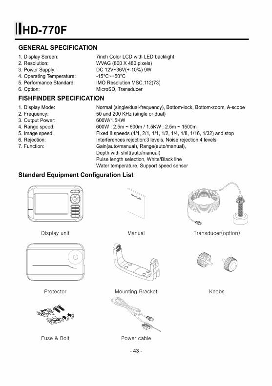
HD-770F GENERAL SPECIFICATION 1. Display Screen: 7inch Color LCD with LED backlight 2. Resolution: WVAG (800 X 480 pixels) 3. Power Supply: DC 12V~36V(+-10%) 9W 4. Operating Temperature: -15°C~+50°C 5. Performance Standard: IMO Resolution MSC.112(73) 6. Option: MicroSD, Transducer
FISHFINDER SPECIFICATION 1. Display Mode: Normal (single/dual-frequency), Bottom-lock, Bottom-zoom, A-scope 2. Frequency: 50 and 200 KHz (single or dual) 3. Output Power: 600W/1.5KW 4. Range speed: 600W : 2.5m ~ 600m / 1.5KW : 2.5m ~ 1500m 5. Image speed: Fixed 8 speeds (4/1, 2/1, 1/1, 1/2, 1/4, 1/8, 1/16, 1/32) and stop 6. Rejection: Interferences rejection:3 levels, Noise rejection:4 levels 7. Function: Gain(auto/manual), Range(auto/manual), Depth with shift(auto/manual) Pulse length selection, White/Black line Water temperature, Support speed sensor
Standard Equipment Configuration List
Display unit Manual Transducer(option)
Protector Mounting Bracket Knobs
Fuse & Bolt Power cable
- 44 -
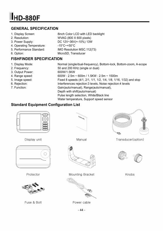
HD-880F GENERAL SPECIFICATION 1. Display Screen: 8inch Color LCD with LED backlight 2. Resolution: WVAG (800 X 600 pixels) 3. Power Supply: DC 12V~36V(+-10%) 13W 4. Operating Temperature: -15°C~+50°C 5. Performance Standard: IMO Resolution MSC.112(73) 6. Option: MicroSD, Transducer
FISHFINDER SPECIFICATION 1. Display Mode: Normal (single/dual-frequency), Bottom-lock, Bottom-zoom, A-scope 2. Frequency: 50 and 200 KHz (single or dual) 3. Output Power: 600W/1.5KW 4. Range speed: 600W : 2.5m ~ 600m / 1.5KW : 2.5m ~ 1500m 5. Image speed: Fixed 8 speeds (4/1, 2/1, 1/1, 1/2, 1/4, 1/8, 1/16, 1/32) and stop 6. Rejection: Interferences rejection:3 levels, Noise rejection:4 levels 7. Function: Gain(auto/manual), Range(auto/manual), Depth with shift(auto/manual) Pulse length selection, White/Black line Water temperature, Support speed sensor
Standard Equipment Configuration List
Display unit Manual Transducer(option)
Protector Mounting Bracket Knobs
Fuse & Bolt Power cable
- 45 -
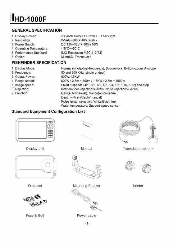
HD-1000F GENERAL SPECIFICATION 1. Display Screen: 10.2inch Color LCD with LED backlight 2. Resolution: WVAG (800 X 480 pixels) 3. Power Supply: DC 12V~36V(+-10%) 16W 4. Operating Temperature: -15°C~+50°C 5. Performance Standard: IMO Resolution MSC.112(73) 6. Option: MicroSD, Transducer
FISHFINDER SPECIFICATION 1. Display Mode: Normal (single/dual-frequency), Bottom-lock, Bottom-zoom, A-scope 2. Frequency: 50 and 200 KHz (single or dual) 3. Output Power: 600W/1.5KW 4. Range speed: 600W : 2.5m ~ 600m / 1.5KW : 2.5m ~ 1500m 5. Image speed: Fixed 8 speeds (4/1, 2/1, 1/1, 1/2, 1/4, 1/8, 1/16, 1/32) and stop 6. Rejection: Interferences rejection:3 levels, Noise rejection:4 levels 7. Function: Gain(auto/manual), Range(auto/manual), Depth with shift(auto/manual) Pulse length selection, White/Black line Water temperature, Support speed sensor
Standard Equipment Configuration List
Display unit Manual Transducer(option)
Protector Mounting Bracket Knobs
Fuse & Bolt Power cable

- 46 -
- 47 -
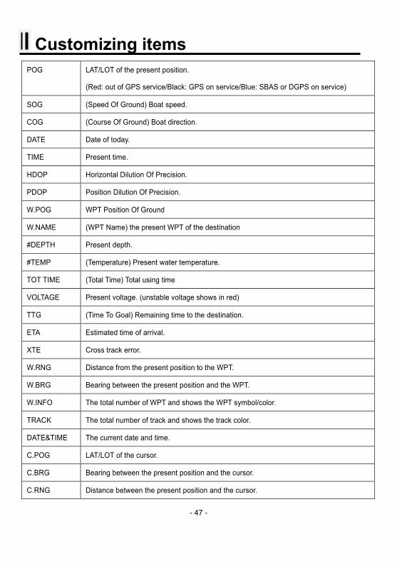
Customizing items POG LAT/LOT of the present position.
(Red: out of GPS service/Black: GPS on service/Blue: SBAS or DGPS on service)
SOG (Speed Of Ground) Boat speed.
COG (Course Of Ground) Boat direction.
DATE Date of today.
TIME Present time.
HDOP Horizontal Dilution Of Precision.
PDOP Position Dilution Of Precision.
W.POG WPT Position Of Ground
W.NAME (WPT Name) the present WPT of the destination
#DEPTH Present depth.
#TEMP (Temperature) Present water temperature.
TOT TIME (Total Time) Total using time
VOLTAGE Present voltage. (unstable voltage shows in red)
TTG (Time To Goal) Remaining time to the destination.
ETA Estimated time of arrival.
XTE Cross track error.
W.RNG Distance from the present position to the WPT.
W.BRG Bearing between the present position and the WPT.
W.INFO The total number of WPT and shows the WPT symbol/color.
TRACK The total number of track and shows the track color.
DATE&TIME The current date and time.
C.POG LAT/LOT of the cursor.
C.BRG Bearing between the present position and the cursor.
C.RNG Distance between the present position and the cursor.

- 48 -
- 49 -
Display Unit Installation
Smart7/8/10 series brings expandable display technology to your bridge or navigation station. A careful
installation will assure maximum benefit from Smart7/8/10 series integrated features.
Display Unit Location Select a location for your Smart7/8/10 series display unit that provides easy viewing from all likely
operator’s positions. The display unit is designed to be mounted on either a console or from an
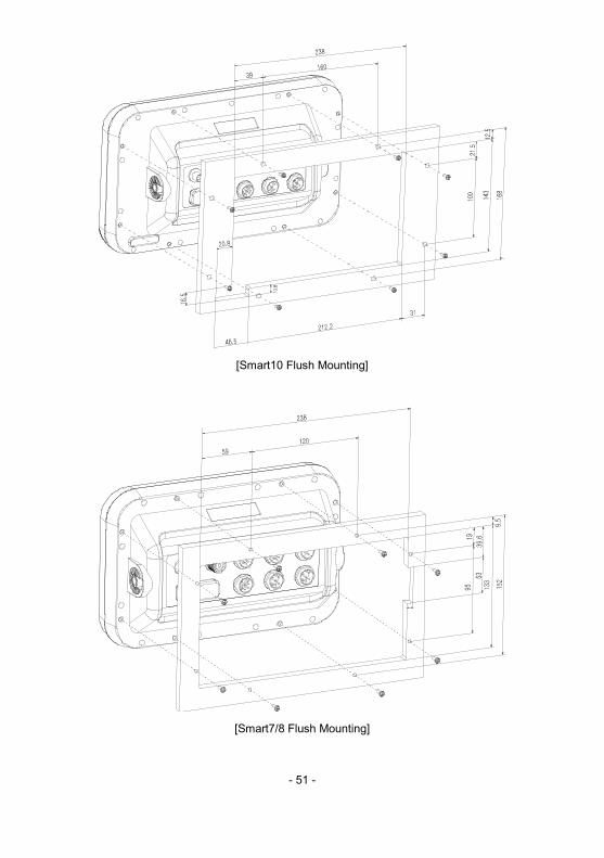
overhead surface. The Smart7/8/10 series display is also designed for flush mounting using six
threaded holes on the rear panel. Locate the display in an area with protection from the elements and
avoid direct sunlight on the viewing window. Also, consider access to the rear panel of the unit for
connecting power and cables to the various remote sensors. The mounting surface must be flat and
solid to support the unit and prevent vibration. There should be access to the inside of the surface to
permit through bolt fastening for the mounting bracket.
Display Unit Installation Temporarily install the mounting bracket on the Genesis display unit and place the unit at the selected
location.
CAUTION The Smart7/8/10 series display unit is unstable when the mounting bracket is not secured. Hold the
unit in place at all times.
Check the suitability of the location and make any adjustments. When all is satisfactory, use the holes
in the mounting bracket as a guide and mark the holes locations on the mounting surface.
Drill a 1/4 in. diameter hole at each marked location. Mount the Smart7/8/10 series display bracket
using bolts through the mounting surface. Place large flat washers on the opposite side of the
mounting surface from the bracket and then install lock washers and nuts. Tighten securely.
- 50 -
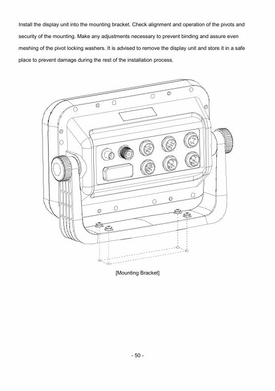
Install the display unit into the mounting bracket. Check alignment and operation of the pivots and
security of the mounting. Make any adjustments necessary to prevent binding and assure even
meshing of the pivot locking washers. It is advised to remove the display unit and store it in a safe
place to prevent damage during the rest of the installation process.
[Mounting Bracket]
- 51 -
[Smart10 Flush Mounting]
[Smart7/8 Flush Mounting]
- 52 -
- Power Connection Power is supplied to the Smart7/8/10 series Charting System through a connector on the rear panel of
the display unit.
Route the power cable from the Smart7/8/10 series location to the ship’s power distribution panel.
Connect the black wire to a battery negative (-) terminal of the power panel.
Connect the white wire to a fused battery positive (+) terminal of the power panel ( 12 to 24 Vdc
nominal). If a fused terminal is not available, install an in-line fuse holder.
- Care and Cleaning Smart7/8/10 series is made to withstand marine elements but a little care ensures a trouble free life.
Accumulations of salt and sand, if not removed, will eventually mar the finish. No solvents or harsh
cleaners should be used. The display unit may be wiped down with a damp cloth while avoiding the
display window. Be careful not to scratch the display window surface. Gently remove any sand or other
grit particles before cleaning the display window. The display window should be cleaned only with
water and a clean soft cloth using very light pressure.
- 53 -
Transducer Installation
An input designation means, in put to Fishfinder unit and an output designation means, output from
Smart series. Sensors will have similar designations, but from the sensors point of view. Therefore, a
sensor output will connect to an smart series input and a sensor input will connect to an Fishfinder unit
output.
Transducer Installation
If you have chosen a Sonar option for your fishfinder a transducer must be installed on your vessel
unless an exiting compatible transducer is installed. The installation of sonar transducers requires
some planning and skill to achieve the best result. It is strongly advised hat you read the installation
instructions completely before starting. The two basic types of transducers are transom mount and
through-hull mount. There are variations within each type to provide for options such as temperature
sensors, speed sensors and for different beam angels and sonar frequencies. Several different
transducers may be used with the Smart series. Refer to the optional Equipment list for the variations
available.
CAUTION
Mounting a sonar transducer for your digital fishfinder requires drilling holes into the hull of your boat
which could affect its water integrity. Therefore, installation should be attempted only by qualified
individuals. If you have any doubt about your ability to complete the process successfully, we
recommend you obtain the services of a HAIYANG dealer or marine service center with knowledge
and experience in transducer installation.
Since your digital fishfinder performance depends upon how well the transducer is installed, please
carefully observe the following mounting procedures.
For proper performance, the transducer’s mounting location must be chosen carefully. The transducer
must be mounted in a location that is free from turbulence and air bubbles created by movement of the
boat through water. Air bubbles greatly reduce the efficiency of the transducer. It is also strongly
- 54 -
recommended, for transom mounted transducers, the transducer be mounted in an area with the least amount of disturbed water passing under the transom. To determine the best mounting location,
operate the boat at several different speeds and observe the water as it passes under the transom.
Turbulence caused by the trim tabs, motor mounting, the keel, and lifting strakes.
Transom Mounting
Transducers designed for transom mounting give good performance when installed on most boat
types, however, the transom transducer style should not be used on boats with inboard engines.
For boats with poor water flow under the transom or on in-boards, consider selecting a through-hull
transducer. HAIYANG offers many styles of transducers.
Determine the transducer mounting place by referring to the steps mentioned above. For best result,
the transducer face should be level. Also, the transducer face should be mounted from flush to 1/4
inch below the under surface of the hull. The trailing edge of the housing should be about 1/8 inch
below the leading edge. The adjustable stainless steel bracket is designed to allow fine tuning of the
transducer position once the installation is completed.
Route the transducer cable as far as possible away from the boat’s power cables, engine controls and
other electrical cables. Do not route transducer cables near your VHF radio power or antenna cables.
Assemble the transducer using the brackets and hardware supplied. Actual fastening to the hull of
your boat depends upon the hull construction and hull material. If additional items must be used, be
sure to obtain marine stainless steel hardware. Also, be sure to use marine waterproof sealant on all
through hull fastenings. Do not use silicone RTV, since it does not have long life underwater.
Transom Transducer Maintenance
If your boat is kept in the water, sea growth can quickly accumulate on the face of the transducer. In
just two weeks in some locations, your Sonar performance could be affected. It is recommended that
at least the face of the transducer be coated with special transducer antifouling paint. Alternatively, the
entire transducer can be painted and is easier to keep clean. Do not use regular antifouling paint.
All copper base antifouling paints are unsatisfactory and will prevent normal operation. If fouling does
occur, use a stiff brush or putty knife to remove growth. Be careful not to gouge the face of the
Transducer. Occasional wet sanding of the transducer face is permissible with #220 grit or finer wet or
- 55 -
dry paper.
Do not use solvents to clean your transducer. The high impact polycarbonate housing is very durable
but solvents will destroy it. Keep acetone, MEK, lacquer thinner and most other thinner/solvents away
from your transducer.
Through-hull Transducers
Through-hull transducers are recommended for in-boards and other vessels with disturbed water flow
under the transom. HAIYANG offers several models of bronze through-hull transducers. To enjoy the
full capability of your Sonar, select a dual frequency model with temperature sensor. Sturdy bronze
construction assures a secure installation and provides a strong base for fairing blocks, if needed, to
compensate for hull shape.
The transducer should be installed in a location free of bubbles and away from disturbed water flow.
Smooth water flow around the transducer and along its surface is very important for consistent
operation.
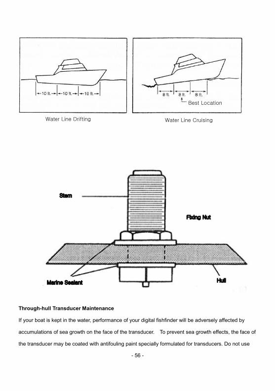
Areas in the center third of water line length at cruising speed are usually satisfactory.
Locations forward of the engine and in a flat area near the center line of the boat are preferred. Do not
install the transducer behind water intakes, other through-hull fittings or irregularities in the hull.
Dead-rise
On hulls with dead-rise of 5 or less, the transducer may be mounted directly through the hull. Where
dead-rise is greater than 5, fairing blocks must be used to orient the face of the transducer parallel
with the water surface.
In this case, no fairing block is necessary. To prevent leakage, any gaps between the stem threads
and holes drilled in the hull should be completely filled with waterproof marine sealant.
Tighten the stem nuts securely but do not over tighten. In this situation, install fairing blocks both
inside and outside the hull. Install the transducer with the face aiming straight down. To prevent
leakage, any gaps between the stem threads and holes drilled in the hull should be completely filled
with waterproof marine sealant. Tighten the stem nuts securely but do not over tighten.
- 56 -
Through-hull Transducer Maintenance
If your boat is kept in the water, performance of your digital fishfinder will be adversely affected by
accumulations of sea growth on the face of the transducer. To prevent sea growth effects, the face of
the transducer may be coated with antifouling paint specially formulated for transducers. Do not use
Water Line Drifting Water Line Cruising
Best Location
Stem
Marine Sealant
Fixing Nut
will be adversely affected by
accumulations of sea growth on the face of the transducer. To prevent sea growth effects, the face of
the transducer may be coated with antifouling paint specially formulated for transducers. Do not use
Line Cruising
Best Location
Hull
Fixing Nut
- 57 -
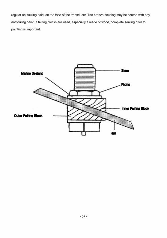
regular antifouling paint on the face of the transducer. The bronze housing may be coated with any
antifouling paint. If fairing blocks are used, especially if made of wood, complete sealing prior to
painting is important.
Marine Sealant Stem
Fixing
Outer Fairing Block
Hull
Inner Fairing Block

- 58 -
- 59 -
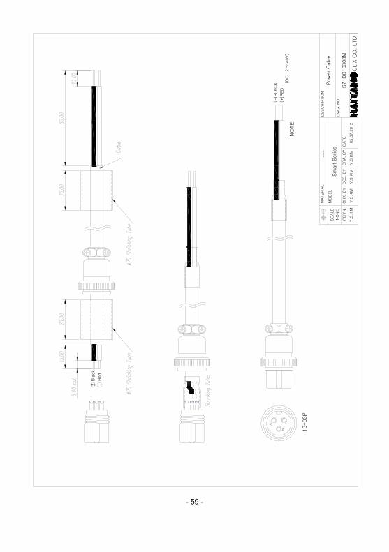
DESC
RIP
TIO
N
DW
G.
NO
.
DES. B
Y
NO
NE
SC
ALE
PER
'N
MO
DEL
CH
K. B
Y
MATERIA
L
DRA. B
Y
---
Y.S
.KIM
OLIX
CO
.,LTD
DATE
05.0
7.2
012
Sm
art S
eries
Y.S
.KIM
Pow
er
Cable
S7-D
C10303M
Y.S
.KIM
Y.S
.KIM
16-03P
Red
Bla
ck
NO
TE
2 1
3
2
1
(-)B
LAC
K
(+)R
ED
(DC
12 ~
40V)
- 60 -
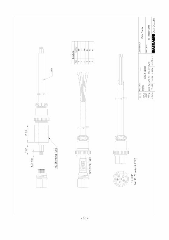
DESC
RIP
TIO
N
DW
G. N
O.
DES. B
Y
NO
NE
SC
ALE
PER'N
MO
DEL
CH
K. B
Y
MATER
IAL
DRA. B
Y
---
Y.S
.KIM
OLIX
CO
.,LTD
DATE
05.0
7.2
012
Sm
art S
ere
is
Y.S
.KIM
Data
Cable
S7-D
C10103M
Y.S
.KIM
Y.S
.KIM
To H
D-70 s
eries (
J2/J
3)
16-06P
Shrinki
ng T
ube
?20
Shrinki
ng T
ube
15.0
07.0
0
3.0
0 c
ut
Cable
1 653 42
1
6
5
3
4
2
- 61 -
8
1
85 6 7431 2
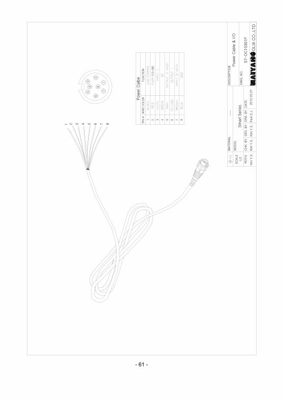
(12~
36)
FU
NC
TIO
NPIN
#W
IRE C
OLO
RPow
er
Calb
e
2 43 5 76 81
Kim
Y.S
.Kim
Y.S
.Kim
Y.S
.
DRA.
BY
Park
D.J
.
Sm
art S
eries
CH
K.
BY
PER'N
DES. B
Y
MO
DEL
MATER
IAL
SC
ALE
1/2
2012.0
5.0
7
DATE
OLIX
CO
.,LTD
S7-D
C10301P
DESC
RIP
TIO
N---
DW
G.
NO
.
Pow
er
Cable
& I/O
62
54
3
7
- 62 -
Kim
Y.S
.Kim
Y.S
.Kim
Y.S
.
DRA. B
Y
Souk.
J.E.
CH
K. B
YPER
'ND
ES. B
Y
2014.0
2.0
5.
DATE
DW
G.
NO
.
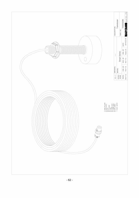
---
DESC
RIP
TIO
N
NO
NE
SC
ALE
MATER
IAL
MO
DEL
Sm
art S
eries
'*' m
ark
: option
OLIX
CO
.,LTD
Tra
nsduser
1
SPD
_PU
LSE*
2
SPD
_VC
C*
3
TD
14
TD
_GN
D5
TD
26
TEM
P_V
CC
7
TEM
P_S
IG*
8
SPD
_GN
D*
TD
SS502M
- 63 -
OLIX
CO
.,LTD
Kim
Y.S
.Kim
Y.S
.Kim
Y.S
.
DRA.
BY
Souk.
J.E.
CH
K.
BY
PER
'ND
ES.
BY
201.0
2.0
5
DATE
DW
G.
NO
.
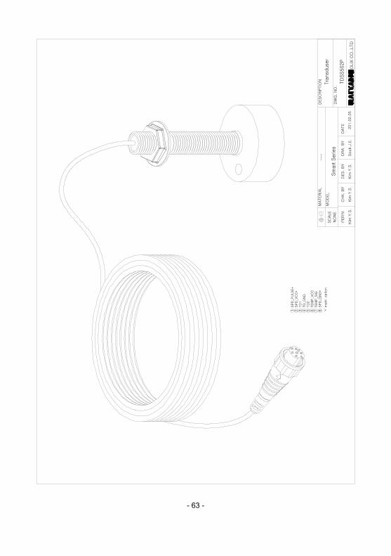
---
DESC
RIP
TIO
N
NO
NE
SC
ALE
MATER
IAL
MO
DEL
Sm
art S
eries
'*' m
ark
: option
Tra
nsduser
1 SPD
_PU
LSE*
2 SPD
_VC
C*
3
TD
14 TD
_GN
D5
TD
26 TEM
P_V
CC
7 TEM
P_S
IG8 SPD
_GN
D*
TD
SS502P

- 64 -
- 65 -
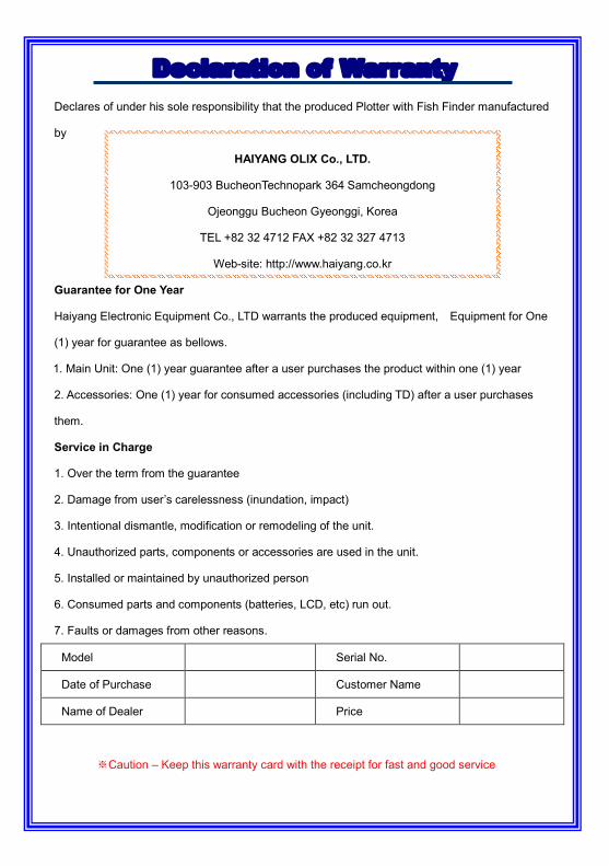
Declaration of Warranty Declares of under his sole responsibility that the produced Plotter with Fish Finder manufactured
by
HAIYANG OLIX Co., LTD.
103-903 BucheonTechnopark 364 Samcheongdong
Ojeonggu Bucheon Gyeonggi, Korea
TEL +82 32 4712 FAX +82 32 327 4713
Web-site: http://www.haiyang.co.kr
Guarantee for One Year
Haiyang Electronic Equipment Co., LTD warrants the produced equipment, Equipment for One
(1) year for guarantee as bellows.
1. Main Unit: One (1) year guarantee after a user purchases the product within one (1) year
2. Accessories: One (1) year for consumed accessories (including TD) after a user purchases
them.
Service in Charge
1. Over the term from the guarantee
2. Damage from user’s carelessness (inundation, impact)
3. Intentional dismantle, modification or remodeling of the unit.
4. Unauthorized parts, components or accessories are used in the unit.
5. Installed or maintained by unauthorized person
6. Consumed parts and components (batteries, LCD, etc) run out.
7. Faults or damages from other reasons.
Model Serial No.
Date of Purchase Customer Name
Name of Dealer Price
※Caution – Keep this warranty card with the receipt for fast and good service