importance and need of accurate modelling of soil of high ...figure 5 wenner method and...
TRANSCRIPT
International Journal of Electrical and Computer Engineering. ISSN 0974-2190 Volume 7, Number 1 (2015), pp. 29-43 © International Research Publication House http://www.irphouse.com
29
Importance and Need of Accurate Modelling of Soil
of High Voltage Substation for Optimal Designing of
Grounding System
Rajesh Kumar
Assistant Manager (Technical), Delhi Transco Ltd (DTL), Delhi, India.
E-mail: [email protected]
Dr Kamal Bansal
Professor, UPES, Dehradhun, India.
E-mail:. [email protected]
Dr Devender Kumar saini
Assistant Professor, UPES, Dehradhun, India.
Email:[email protected]
Dr IPS Paul
Ex Additional Director & Currently Professor and Dean at HRIT, Ghaziabad, India
E-mail: [email protected]
Abstract
The main objective of grounding electrical systems is to provide a suitably low resistance path for the discharge of fault current which ultimately provide safety to working personnel and costly installed equipments in the substation. The flow of heavy fault current results in rise of potential in the substation area and with respect to remote ground. There is need to ensure that the ground potential rise, and touch and step voltages are within permissible limit, an accurate soil model is required to design grounding system of the substation that ensures that the resistance of the grounding grid through the earth is sufficiently low. Soil resistivity data is of fundamental importance in performing grounding system analyses. Reliable data is required to achieve good correlation between design and measured grounding system performance. This soil model is derived from the accurate soil resistivity measurement structure at the proposed grid location. This paper provides a overview of 4 pin method for measurement of resistivity & provide the method of single and two layer soil modelling of substation area with help of MATLAB GUI software and provides an example to understand the modelling procedure.
Key Words: Grounding, Soil Resistivity, Substation, Resistance, Single and Two Layer soil Model

30 Rajesh Kumar et al
1. INTRODUCTION
Grounding/ Earthing means making a connection to the general mass of earth. The use of grounding is so widespread in an electric system that at practically every point in the system, from the generators to the consumers’ equipment, earth connections are made.[3,4] Earlier, the design criterion was to achieve lowest earth resistance, However, the modern design criterion for grounding system is to achieve low earth resistance and also to achieve safe’ step-potential’, ‘touch potential’ and voltage gradient during an
earth fault between conductor and any of the earthed bodies in the substation.
Fig 1 Grounding Mat of the Substation
2. Step Potential And Touch Potential
During an earth-fault in the substation the earth fault current flows from the fault-point to earth via the metallic path having certain total resistance R. This flow of fault current (If) flowing through resistance R causes a voltage drop V = IfR0. This voltage drop results in a voltage-gradient along the substation floor during the earth faults. This voltage gradient should be held in safe limits by proper design of station grounding system.[3]
Importance and Need of Accurate Modelling of Soil 31
31
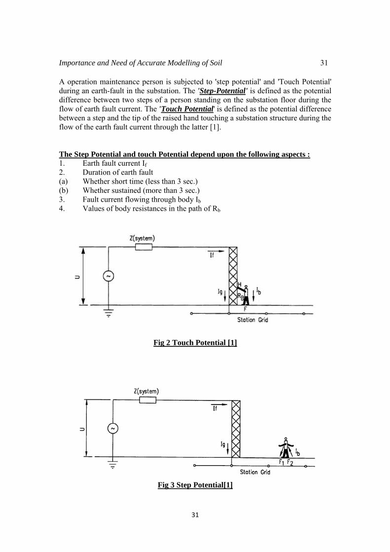
A operation maintenance person is subjected to 'step potential' and 'Touch Potential' during an earth-fault in the substation. The 'Step-Potential' is defined as the potential difference between two steps of a person standing on the substation floor during the flow of earth fault current. The 'Touch Potential' is defined as the potential difference between a step and the tip of the raised hand touching a substation structure during the flow of the earth fault current through the latter [1]. The Step Potential and touch Potential depend upon the following aspects :
1. Earth fault current If 2. Duration of earth fault (a) Whether short time (less than 3 sec.) (b) Whether sustained (more than 3 sec.) 3. Fault current flowing through body Ib 4. Values of body resistances in the path of Rb
Fig 2 Touch Potential [1]
Fig 3 Step Potential[1]
32 Rajesh Kumar et al
3. Concept of Soil Resistivity
Soil resistivity can be defined as the resistance between the opposite sides of a cube of soil with a side dimension of one meter. Soil resistivity values in vary widely, depending on the type of terrain; e.g., silt on a riverbank may have a resistivity value around 1.5 Ω-m, whereas dry sand or granite in mountainous country may have values higher than 10,000 Ω-m. The factors that affect resistivity may be summarized as follows [5,13]: 1. Type of earth (e.g., clay, loam, sandstone, granite).
2. Stratification of layers of different types of soil (e.g., loam backfill on a clay
base).
3. Moisture content: resistivity may fall rapidly as the moisture content is increased, but after a value of about 20%, the rate is much less. Soil with moisture content greater than 40% is rarely encountered.
4. Temperature: above the freezing point, the effect of temperature on earth
resistivity is negligible.
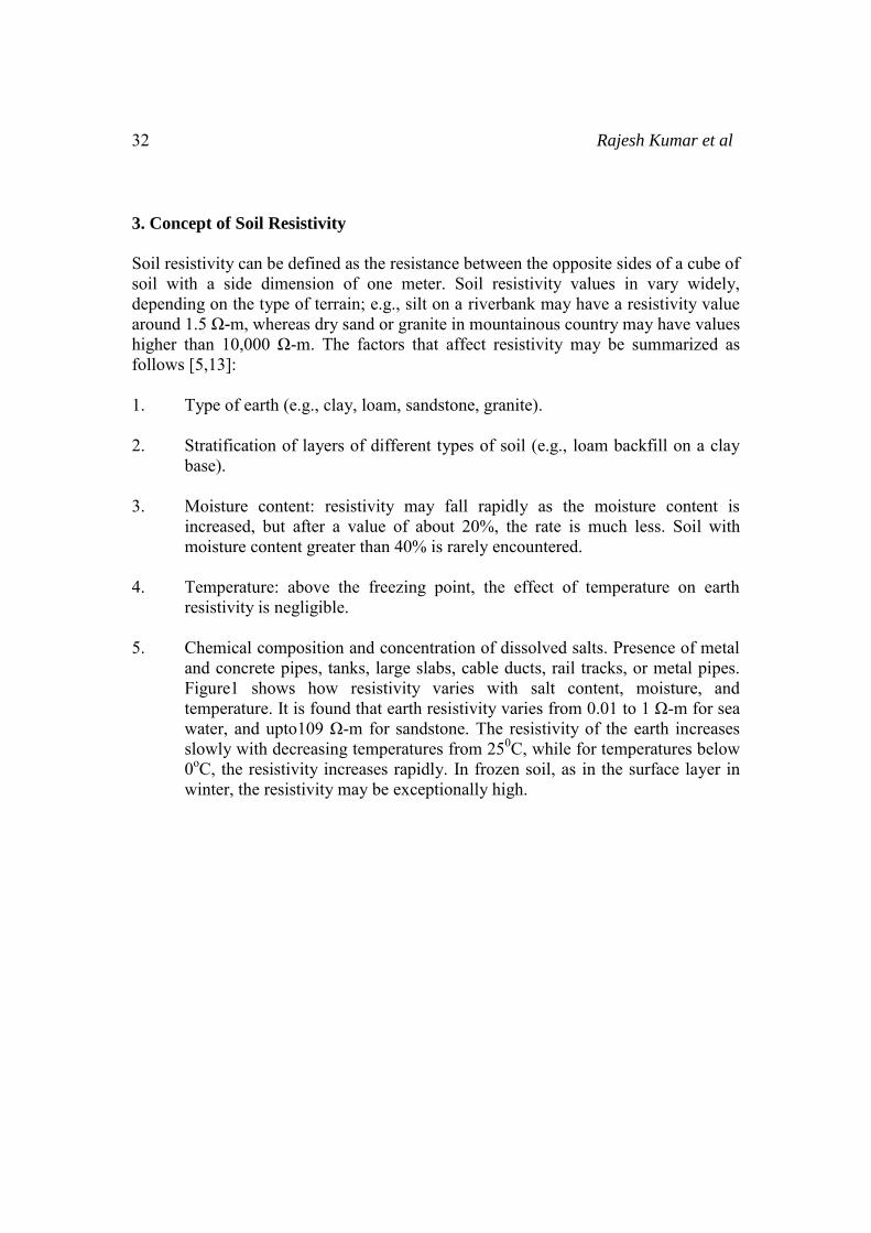
5. Chemical composition and concentration of dissolved salts. Presence of metal and concrete pipes, tanks, large slabs, cable ducts, rail tracks, or metal pipes. Figure1 shows how resistivity varies with salt content, moisture, and temperature. It is found that earth resistivity varies from 0.01 to 1 Ω-m for sea water, and upto109 Ω-m for sandstone. The resistivity of the earth increases slowly with decreasing temperatures from 250C, while for temperatures below 0oC, the resistivity increases rapidly. In frozen soil, as in the surface layer in winter, the resistivity may be exceptionally high.
Importance and Need of Accurate Modelling of Soil 33
33
Fig 4 Impact of Salt, Moisture and Temperature on Soil Resistivity
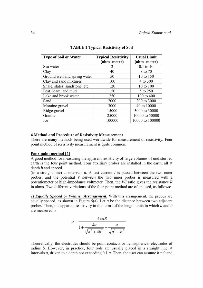
Table 1 shows the resistivity values for various soils and rocks that might occur in different grounding system designs. The electrical properties of the soil are determined by the thicknesses of layers and their changes in resistivity, resistivity is dependent upon water and chemical content, as well as soil texture. Usually there are several soil layers, each having a different resistivity, in which case the soil is said to be non-uniform. Lateral changes may also occur, but, in general, these changes are gradual and negligible, at least in the vicinity of a site where a grid is to be installed. In most cases, measurements will show that the resistivity, ρ, is mainly a function of
depth. The interpretation of the measurements consists of establishing a simple equivalent function to yield the best approximation of soil resistivity’s to determine the layer model.
34 Rajesh Kumar et al
TABLE 1 Typical Resistivity of Soil
Type of Soil or Water Typical Resistivity
(ohm- meter)
Usual Limit
(ohm- meter)
Sea water 2 0.1 to 10 Clay 40 8 to 70 Ground well and spring water 50 10 to 150 Clay and sand mixtures 100 4 to 300 Shale, slates, sandstone, etc. 120 10 to 100 Peat, loam, and mud 150 5 to 250 Lake and brook water 250 100 to 400 Sand 2000 200 to 3000 Moraine gravel 3000 40 to 10000 Ridge gravel 15000 3000 to 30000 Granite 25000 10000 to 50000 Ice 100000 10000 to 100000
4 Method and Procedure of Resistivity Measurement
There are many methods being used worldwide for measurement of resistivity. Four point method of resistivity measurement is quite common.
Four-point method [2]
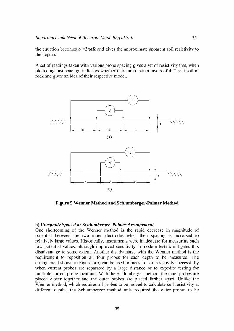
A good method for measuring the apparent resistivity of large volumes of undisturbed earth is the four point method. Four auxiliary probes are installed in the earth, all at depth b and spaced (in a straight line) at intervals a. A test current I is passed between the two outer probes, and the potential V between the two inner probes is measured with a potentiometer or high-impedance voltmeter. Then, the V/I ratio gives the resistance R
in ohms. Two different variations of the four-point method are often used, as follows: a) Equally Spaced or Wenner Arrangement. With this arrangement, the probes are equally spaced, as shown in Figure 5(a). Let a be the distance between two adjacent probes. Then, the apparent resistivity in the terms of the length units in which a and b
are measured is
Theoretically, the electrodes should be point contacts or hemispherical electrodes of radius b. However, in practice, four rods are usually placed in a straight line at intervals a, driven to a depth not exceeding 0.1 a. Then, the user can assume b = 0 and
Importance and Need of Accurate Modelling of Soil 35
35
the equation becomes ρ =2πaR and gives the approximate apparent soil resistivity to the depth a. A set of readings taken with various probe spacing gives a set of resistivity that, when plotted against spacing, indicates whether there are distinct layers of different soil or rock and gives an idea of their respective model.
Figure 5 Wenner Method and Schlumberger-Palmer Method
b) Unequally Spaced or Schlumberger–Palmer Arrangement.
One shortcoming of the Wenner method is the rapid decrease in magnitude of potential between the two inner electrodes when their spacing is increased to relatively large values. Historically, instruments were inadequate for measuring such low potential values, although improved sensitivity in modern testers mitigates this disadvantage to some extent. Another disadvantage with the Wenner method is the requirement to reposition all four probes for each depth to be measured. The arrangement shown in Figure 5(b) can be used to measure soil resistivity successfully when current probes are separated by a large distance or to expedite testing for multiple current probe locations. With the Schlumberger method, the inner probes are placed closer together and the outer probes are placed farther apart. Unlike the Wenner method, which requires all probes to be moved to calculate soil resistivity at different depths, the Schlumberger method only required the outer probes to be
36 Rajesh Kumar et al
repositioned for subsequent measurements. Reducing the number of probes to be repositioned for each test makes the Schlumberger method a faster choice for testing at different depths. The equation to be used in this case can be easily determined. If the depth of burial of the electrodes b is small compared to their separation d and c, and c > 2d, then the measured apparent resistivity can be calculated as follows:
Ρ=π(c+d)R/d
5.0 Different Soil Models
Uniform soil model is seldom found in the field. Grounding design engineers usually come across the following types of soil models.[19]
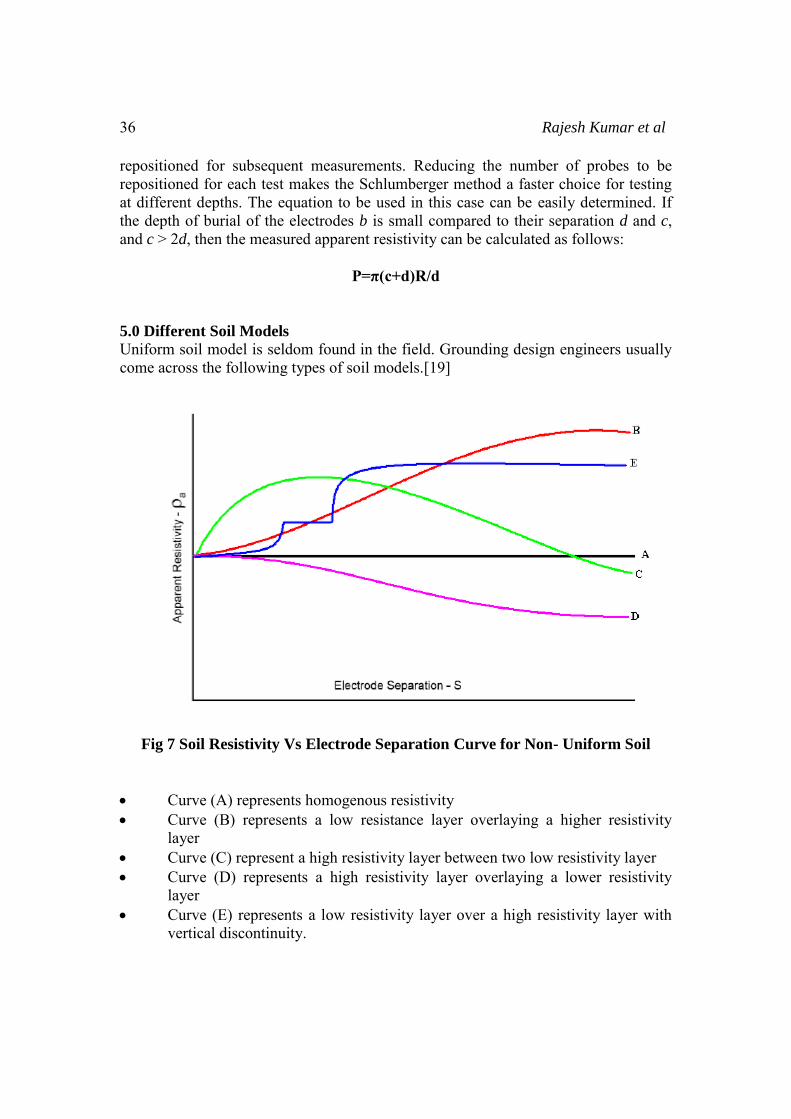
Fig 7 Soil Resistivity Vs Electrode Separation Curve for Non- Uniform Soil
Curve (A) represents homogenous resistivity Curve (B) represents a low resistance layer overlaying a higher resistivity
layer Curve (C) represent a high resistivity layer between two low resistivity layer Curve (D) represents a high resistivity layer overlaying a lower resistivity
layer Curve (E) represents a low resistivity layer over a high resistivity layer with
vertical discontinuity.
Importance and Need of Accurate Modelling of Soil 37
37
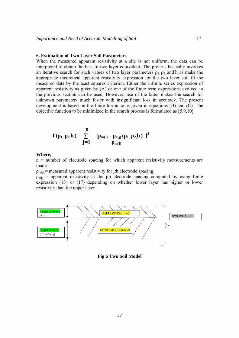
6. Estimation of Two Layer Soil Parameters
When the measured apparent resistivity at a site is not uniform, the data can be interpreted to obtain the best fit two layer equivalent. The process basically involves an iterative search for such values of two layer parameters ρ1, ρ2, and h as make the appropriate theoretical apparent resistivity expression for the two layer soil fit the measured data by the least squares criterion. Either the infinite series expression of apparent resistivity as given by (A) or one of the finite term expressions evolved in the previous section can be used. However, use of the latter makes the search for unknown parameters much faster with insignificant loss in accuracy. The present development is based on the finite formulae as given in equations (B) and (C). The objective function to be minimized in the search process is formulated as [5,9,10]
n
f (ρ1, ρ2,h ) = ∑ [ρm(j) - ρc(j) (ρ1, ρ2,h ) ]2
j=1 ρm(j)
Where,
n = number of electrode spacing for which apparent resistivity measurements are made. ρm(j) = measured apparent resistivity for jth electrode spacing. ρc(j) = apparent resistivity at the jth electrode spacing computed by using finite expression (13) or (17) depending on whether lower layer has higher or lower resistivity than the upper layer
Fig 6 Two Soil Model
38 Rajesh Kumar et al
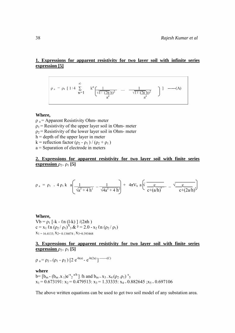
1. Expressions for apparent resistivity for two layer soil with infinite series
expression [5]
Where,
ρ a = Apparent Resistivity Ohm- meter ρ1 = Resistivity of the upper layer soil in Ohm- meter ρ2 = Resistivity of the lower layer soil in Ohm- meter h = depth of the upper layer in meter k = reflection factor (ρ2 - ρ1 ) / (ρ2 + ρ1 ) a = Separation of electrode in meters 2. Expressions for apparent resistivity for two layer soil with finite series
expression ρ2> ρ1 [5]
ρ a = ρ1 + 4 ρ1 k a 1 _ 1 + 4πVb a √ ___c____ _ √___c____ √a
2 + 4 h2 √4a
2 + 4 h2 c+(a/h)ᵝ c+(2a/h)ᵝ
Where,
Vb = ρ1 [-k - ℓn (l-k) ] /(2πh ) c = x1 ℓn (ρ2 / ρ1)X
3 & ᵝ = 2.0 - x2 ℓn (ρ2 / ρ1) x1 = 16.4133; x2= 0.136074 ; x3=0.393468
3. Expressions for apparent resistivity for two layer soil with finite series
expression ρ2< ρ1 [5]
ρ a = ρ2 + (ρ1 - ρ2 ) [2 e-b(a) - e-b(2a) ] -------(C)
where
b= [bm - (bm -x 1)e-x2
a/h ] /h and bm = x3 - x4 (ρ2 -ρ1) x5 x1 = 0.673191: x2 = 0.479513: x3 = 1.33335: x4 = 0.882645 ;x5 = 0.697106 The above written equations can be used to get two soil model of any substation area.
Importance and Need of Accurate Modelling of Soil 39
39
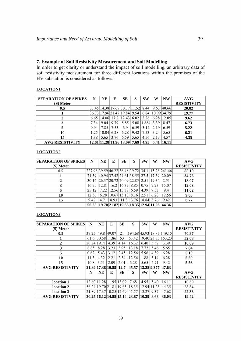
7. Example of Soil Resistivity Measurement and Soil Modelling
In order to get clarity or understand the impact of soil modelling, an arbitrary data of soil resistivity measurement for three different locations within the premises of the HV substation is considered as follows: LOCATION1
SEPARATION OF SPIKES
(S) Meter
N NE E SE S SW W NW AVG
RESISTIVITY
0.5 33.45 14.38 17.67 30.77 11.52 8.44 9.63 40.66 20.82
1 36.73 17.96 21.47 19.84 9.54 6.84 10.99 34.79 19.77
2 6.65 14.06 17.2 12.43 6.02 2.26 6.28 12.05 9.62
3 7.34 9.04 9.79 8.85 5.08 1.884 3.39 8.47 6.73
5 0.94 7.85 7.53 6.9 6.59 3.14 2.19 6.59 5.22
10 1.25 10.04 6.28 6.28 9.42 7.53 3.24 5.65 6.21
15 1.88 5.65 3.76 6.59 5.65 4.56 2.13 4.57 4.35
AVG RESISTIVITY 12.61 11.28 11.96 13.09 7.69 4.95 5.41 16.11 LOCATION2 SEPARATION OF SPIKES
(S) Meter
N NE E SE S SW W NW AVG
RESISTIVITY
0.5 227.96 39.59 46.22 36.48 39.72 34.1 15.26 241.46 85.10
1 71.59 40.94 37.42 24.61 38.55 27.5 17.39 20.09 34.76
2 30.14 26.37 20.72 20.09 22.85 2.51 19.34 2.51 18.07
3 16.95 12.81 16.2 16.39 8.85 0.75 9.23 15.07 12.03
5 25.12 7.22 12.56 15.38 6.59 4.39 7.53 9.4 11.02
10 12.56 6.28 10.67 13.18 8.16 2.51 6.28 12.56 9.03
15 9.42 4.71 8.93 11.3 3.76 18.84 3.76 9.42 8.77
56.25 19.70 21.82 19.63 18.35 12.94 11.26 44.36 LOCATION3
SEPARATION OF SPIKES
(S) Meter
N NE E SE S SW W NW AVG
RESISTIVITY
0.5 39.25 49.8 49.07 21 194.68 45.93 18.87 149.15 70.97
1 61.6 30.58 11.86 53 63.42 19.40 23.55 153.23 52.08
2 20.84 19.71 4.39 4.14 16.32 6.40 5.52 3.39 10.09
3 8.85 8.28 3.23 3.95 13.18 7.72 5.46 5.65 7.04
5 0.62 5.43 3.12 2.45 12.56 5.96 4.39 6.28 5.10
10 11.3 4.32 2.21 2.34 12.56 1.88 3.14 6.28 5.50
15 10.8 3.51 2.09 2.01 6.28 5.65 4.71 9.42 5.56
AVG RESISTIVITY 21.89 17.38 10.85 12.7 45.57 13.28 9.377 47.63 N NE E SE S SW W NW AVG
RESISTIVITY
location 1 12.60 11.28 11.95 13.09 7.68 4.95 5.40 16.11 10.39
location 2 56.24 19.70 21.81 19.63 18.35 12.94 11.25 44.35 25.54
location 3 21.89 17.37 10.85 12.69 45.57 13.27 9.37 47.62 22.33
AVG RESISTIVITY 30.25 16.12 14.88 15.14 23.87 10.39 8.68 36.03 19.42
40 Rajesh Kumar et al
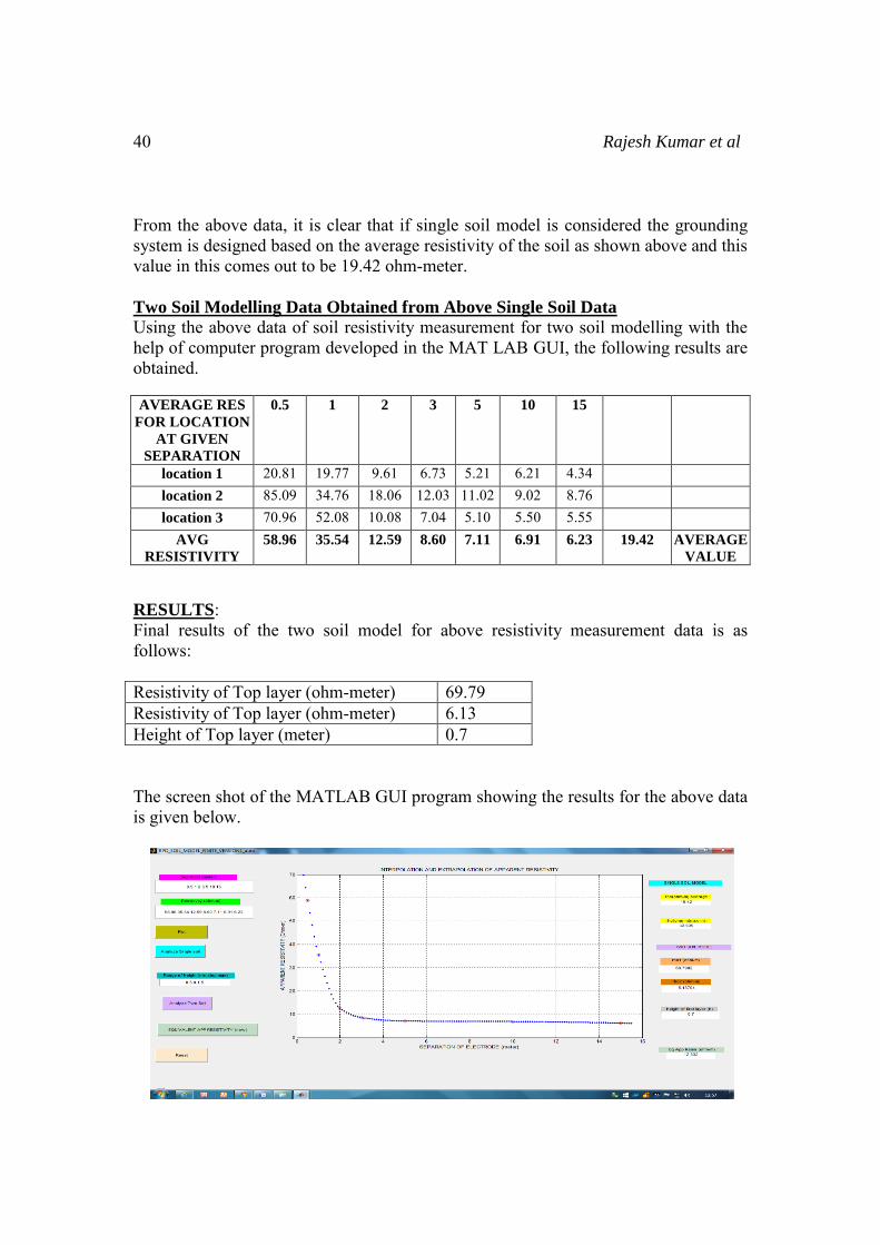
From the above data, it is clear that if single soil model is considered the grounding system is designed based on the average resistivity of the soil as shown above and this value in this comes out to be 19.42 ohm-meter. Two Soil Modelling Data Obtained from Above Single Soil Data
Using the above data of soil resistivity measurement for two soil modelling with the help of computer program developed in the MAT LAB GUI, the following results are obtained. AVERAGE RES
FOR LOCATION
AT GIVEN
SEPARATION
0.5 1 2 3 5 10 15
location 1 20.81 19.77 9.61 6.73 5.21 6.21 4.34 location 2 85.09 34.76 18.06 12.03 11.02 9.02 8.76 location 3 70.96 52.08 10.08 7.04 5.10 5.50 5.55
AVG
RESISTIVITY
58.96 35.54 12.59 8.60 7.11 6.91 6.23 19.42 AVERAGE
VALUE
RESULTS: Final results of the two soil model for above resistivity measurement data is as follows: Resistivity of Top layer (ohm-meter) 69.79 Resistivity of Top layer (ohm-meter) 6.13 Height of Top layer (meter) 0.7
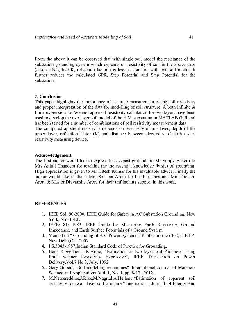
The screen shot of the MATLAB GUI program showing the results for the above data is given below.
Importance and Need of Accurate Modelling of Soil 41
41
From the above it can be observed that with single soil model the resistance of the substation grounding system which depends on resistivity of soil in the above case (case of Negative K, reflection factor ) is less as compare with two soil model. It further reduces the calculated GPR, Step Potential and Step Potential for the substation.
7. Conclusion
This paper highlights the importance of accurate measurement of the soil resistivity and proper interpretation of the data for modelling of soil structure. A both infinite & finite expression for Wenner apparent resistivity calculation for two layers have been used to develop the two layer soil model of the H.V. substation in MATLAB GUI and has been tested for a number of combinations of soil resistivity measurement data. The computed apparent resistivity depends on resistivity of top layer, depth of the upper layer, reflection factor (K) and distance between electrodes of earth tester/ resistivity measuring device.
Acknowledgement
The first author would like to express his deepest gratitude to Mr Sonjiv Banerji & Mrs Anjuli Chandera for teaching me the essential knowledge (basic) of grounding. High appreciation is given to Mr Hitesh Kumar for his invaluable advice. Finally the author would like to thank Mrs Krishna Arora for her blessings and Mrs Poonam Arora & Master Divyanshu Arora for their unflinching support in this work.
REFERENCES
1. IEEE Std. 80-2000, IEEE Guide for Safety in AC Substation Grounding, New York, NY: IEEE
2. IEEE: 81: 1983, IEEE Guide for Measuring Earth Resistivity, Ground Impedance, and Earth Surface Potentials of a Ground System
3. Manual on," Grounding of A C Power Systems,” Publication No 302, C.B.I.P.
New Delhi,Oct. 2007 4. I.S.3043-1987,Indian Standard Code of Practice for Grounding. 5. Hans R.Seedher, J.K.Arora, "Estimation of two layer soil Parameter using
finite wenner Resistivity Expressive", IEEE Transaction on Power Delivery,Vol.7 No.3, July, 1992.
6. Gary Gilbert, "Soil modelling techniques", International Journal of Materials Science and Applications. Vol. 1, No. 1, pp. 8-13., 2012.
7. M.Nessereddine,J.Rizk,M.Nagrial,A.Helleny,“Estimation of apparent soil
resistivity for two - layer soil structure,” International Journal Of Energy And
42 Rajesh Kumar et al
Environment, Volume 4, Issue 4, pp.573-580, 2013. 8. Rodney Urban, Karl Mardira, Session Three:Accurate "Soil Resistivity
Testing for Power System Grounding", Grounding, Lightning & Surge Protection Forum – IDC Technologies
9. Ioannis F. GONOS, Vassiliki T. Kontargyri, Ioannis A. Stathopulos, Antonios X. Moronis, Anastasios P. Sakarellos, Nikolaos I. Kolliopoulos, "Determination Of Two Layer Earth Structure Parameters" XVII International Conference on Electromagnetic Disturbances EMD'2007,Poland
10. Adekitan I. Aderibigbe, Fakolujo A. Olaosebikan," Alogorithm for Determining the Parameters of a Two- Layer Soil Model", World Academy of Science, Engineering and Technology International Journal of Electrical, Computer, Electronics and Communication Engineering Vol:8, No:11, 2014
11. J.Ma, F.P. Dawalibi, R.D.Southey, "Effects of the Changes in IEEE Std. 80 on the Design and Analysis of Power System Gounding", Safe Engineering Services & technologies ltd.
12. R.D.Southey, F.P. Dawalibi, "Improving the Reliability of Power systems with More accurate Grounding System Resistance Estimates", Safe Engineering Services & technologies ltd.
13. F.P. Dawalibi, N.Mitskevitch, "Analysis and Validation of the Performance of Grounding Gystems Buried in Soil Structures Containing heterogeneous volumes", Safe Engineering Services & technologies ltd.
14. Maneesh Kumar, Gagandeep Singh, "Design of Grounding System for an Electrical Substation: An Overview", International Journal of Scientific & Engineering Research, Volume 5, Issue 11, Novemeber - 2014
15. Grzegorz Karnas, Grzegorz Masłowski, Robert Ziemba, Stanisław Wyderka,
Kamil Filik, " Analysis of a Simple Grounding System Installed in a Multilayer Soil", Zeszyty Naukowe Politechniki Rzeszowskiej Nr 287, Elektrotechnika z. 32, 2012
16. J. A. Laver and H. Griffiths, " The Variability of Soils in Grounding Measurements and Grounding System Performance, Rev. Energ. Ren. : Power Engineering (2001) 57-61
17. Att Phayomhom, Somporn Sirisumrannukul, Tirapong Kasirawat, and Arwut Puttarach, "Safety Design Planning of Ground Grid for Outdoor Substations in MEA's Power Distribution System", ECTI transactions on Electrical Engg., Electronics, and Communications vol.9, no.1 February 2011
18. Dwarka Prasad, Dr. H.C Sharma, " Soil Resistivity and Grounding System", International Journal of Management, IT and Engineering, Volume 2, Issue 9 September, 2012.
19. M. Nassereddine, J. Rizk, and G. Nasserddine," Soil Resistivity Data Computations;Single and Two - Layer Soil Resistivity Structure and Its Implication on Grounding Design,” World Academy of Science, Engineering
and Technology Vol:7 2013 20. O.E.Gouda1, G. M.Amer, T. M.EL-Saied, "Factor Affecting the Apparent
Resistivity of Multi-Layer Soil”,Proceedings of the XIVth International Symposium on High Voltage Engineering,Singhua University, Beijing, China,
Importance and Need of Accurate Modelling of Soil 43
43
2005. Authors Biographical Detail:
RAJESH KUMAR was born in Delhi, India. He received the B.Tech. & Master of Engineering (ME) degrees in Electrical Engineering from Delhi College of Engineering, University of Delhi, India in 1999 and 2003, respectively. He is also certified Energy Manager and Auditor. He has worked in 400KV and 220KV Substation for more than 13 years in Delhi Transco Limited (DTL). He has also worked as Deputy Director (Transmission and Distribution) in Delhi Electricity Regulatory Commission (DERC) for 03 years and 06 months. Presently he is working in the OS department of Delhi Transco Limited (DTL).His research interests include high voltage technology, grounding system, protection system computer application and power distribution automation
Dr Kamal Bansal is a Professor in University of Petroleum and Energy Studies, Bidholi, Dehradhun, India. He obtained his B. Tech (Electrical Engineering) degree from Malaviya Regional Engineering College, Jaipur & M. Tech (Power System) from Regional Engineering College Kurukshetra .He completed PhD in “Analysis and Redesigning of watermills for sustainable
development of Uttarakhand”. He is a BEE Certified Energy Auditor and
professional member of Energy Institute U.K.
Dr. Devender Kumar Saini is an Assistant Professor in University of Petroleum and Energy Studies, Bidholi, Dehradhun, India. He obtained his B.Tech(Electrical Engineering) degree from LIET, Alwar, University of Rajasthan, in 2006. He obtained M.Tech.(System and control) and PhD from IIT Roorkee in 2009 and 2012 respectively.
Dr. IPS Paul obtained B.E.(Mech) from MACT, Bhopal, P.G. Diploma in Energy Management-Italy, M.B.A. from Delhi University & PhD from IIT Delhi. He started his career as Assistant Executive Engineer in PSEB, Patiala & worked there for 3 years & 6 months. He further joined NTPC, Badarpur as a Senior Engineer / Engineer & provided his services for 3 years. He further joined NPTI New Delhi as Deputy Director/Director & worked there for 10 years. He further joined CPRI & worked as Joint Director/ Additional Director/ Additional Director Scientist-G for 16 years. Currently, he is working as Professor M. E., DEAN-R&D at BBDIT, HRIT. He has published 19 papers at National and International levels.