implicit decals: interactive editing of repetitive
TRANSCRIPT

HAL Id: hal-00876004https://hal.archives-ouvertes.fr/hal-00876004
Submitted on 23 Oct 2013
HAL is a multi-disciplinary open accessarchive for the deposit and dissemination of sci-entific research documents, whether they are pub-lished or not. The documents may come fromteaching and research institutions in France orabroad, or from public or private research centers.
L’archive ouverte pluridisciplinaire HAL, estdestinée au dépôt et à la diffusion de documentsscientifiques de niveau recherche, publiés ou non,émanant des établissements d’enseignement et derecherche français ou étrangers, des laboratoirespublics ou privés.
Implicit Decals: Interactive Editing of RepetitivePatterns on Surfaces
Erwin de Groot, Brian Wyvill, Loic Barthe, Ahmad Nasri, Paul Lalonde
To cite this version:Erwin de Groot, Brian Wyvill, Loic Barthe, Ahmad Nasri, Paul Lalonde. Implicit Decals: InteractiveEditing of Repetitive Patterns on Surfaces. Computer Graphics Forum, Wiley, 2014, 33 (1), pp.141-151. �10.1111/cgf.12260�. �hal-00876004�

Volume 0 (1981), Number 0 pp. 1–11 COMPUTER GRAPHICS forum
Implicit Decals: Interactive Editing of Repetitive Patterns on
Surfaces
Erwin de Groot1,2, Brian Wyvill3,4, Loïc Barthe5, Ahmad Nasri6, Paul Lalonde7
1University of Calgary (Canada), 2 ASML, 3University of Victoria (Canada), 4University of Bath (UK),5IRIT, Université de Toulouse (France), 6American University of Beirut (Lebanon), 7Microsoft Canada
Abstract
Texture mapping is an essential component for creating 3D models and is widely used in both the game and the
movie industries. Creating texture maps has always been a complex task and existing methods carefully balance
flexibility with ease of use. One difficulty in using texturing is the repeated placement of individual textures over
larger areas. In this paper we propose a method which uses decals to place images onto a model. Our method
allows the decals to compete for space and to deform as they are being pushed by other decals. A spherical
field function is used to determine the position and the size of each decal and the deformation applied to fit the
decals. The decals may span multiple objects with heterogeneous representations. Our method does not require
an explicit parameterization of the model. As such, varieties of patterns including repeated patterns like rocks,
tiles, and scales can be mapped. We have implemented the method using the GPU where placement, size, and
orientation of thousands of decals are manipulated in real time.
Categories and Subject Descriptors (according to ACM CCS): I.3.7 [Computer Graphics]: Computer Graphics—Three-Dimensional Graphics and Realism. Color, shading, shadowing, and texture
1. Introduction
For many computer graphics applications, such as interac-tive computer games and animation, 3D objects appearanceis defined by 2D textures [BN76, HH90, YKH10]. Most tex-turing tools require the determination of an appropriate pa-
rameterization and atlas for polygonal or implicit surfaceswhere no natural parameterization exists [Lév01, ZPKG02,KSG03, ZWT∗05]. Creating such a parameterization byhand is very time consuming and automatic creation suffersrestrictions or compromises the quality of the result, espe-
c© 2013 The Author(s)Computer Graphics Forum c© 2013 The Eurographics Association and Blackwell Publish-ing Ltd. Published by Blackwell Publishing, 9600 Garsington Road, Oxford OX4 2DQ,UK and 350 Main Street, Malden, MA 02148, USA.
E. de Groot et al. / Implicit Decals
cially in the presence of large distortions. As a consequence,the editing and the placement of textures on arbitrary sur-faces remains a tedious task requiring artists to spend muchtime to achieve a desired result.
While it is difficult to limit distortions in the parametrizationfor large textures, it becomes easier when they are composedof repetitive patterns such as dragon scales or giraffe freckles(see Teaser). Large textures are then decomposed in a set ofsmall tiles, often called decals [Ped95], that are individuallypositioned and mapped with a local parametrization on thesurface. These small surface elements can be parametrizedwith very low distortions using exponential maps [SGW06].
However, to be practical for the user, a very large number ofdecals must be positioned and displaced interactively, whichis not feasible with current techniques. A second useful func-tionality would be the ability to define textures across mul-tiple objects which may in addition use different represen-tations (such as meshes, point-set-surfaces and implicit sur-faces).
To this end, we propose the use of a decaling interface whosemodels are free of global parametrization, as suggested bySchmidt et al. [SGW06]. Our method for defining a local pa-rameterization is not bound to the underlying geometry, typi-cally meshes or parametric representations. We use a particlesystem to automatically place cellular pattern elements (de-cals) over the surface of one or more objects. Subsequently,real-time interaction is possible to fine tune each element’sdeformation and placement. Fast local parametrization is ob-tained under the assumption that for small decals, fine dis-tortion control is not required. The use of the Euclidean dis-tance between a surface point and the associated decal cen-tre (i.e. the particle) is then sufficient, thus avoiding the farmore expensive computation of the geodesic distance alongthe surface. This statement is validated by several examplesillustrated in the Teaser and in Figures 13 and 9. Very fastparametrization computation is then performed via the useof spherical field functions, centred on particles. This hasalso the advantage of enabling the application of field defor-mations and implicit composition operators in order to con-trol the shape of decals and the way they cover the surfacearea. These field deformations allow the automatic adjust-ment of the textures when decals overlap such as the eyesof the dragon and the giraffe in the teaser, or when theycompete for space as is the case for the dragon scales andthe giraffe freckles. This is especially important in real-timeinteractive graphics applications, where decals representingpattern elements are mostly required to be similar but notidentical, as shown in our examples.
The main contributions of our method are:
• The very fast computation of local parameterizationsbased on the Euclidean distance over a model. This localparametrization can be computed at arbitrary resolution
and is independent of the underlying geometric represen-tation.
• The technique is simple enough to implement in a pixelshader, without modifying the graphics pipeline nor lim-iting the use of other shaders, and it allows thousands ofdecals to be placed and edited interactively.
• Our decals can compete for space and deform when theyinteract with nearby decals.
• Surface connectivity is not required thus a decal can beplaced across multiple objects or across gaps in an objectwithout changing the object representation.
This paper is organized as follows. After presenting therelated works on texturing with decals (section 2), weexplain how decals can be distributed over surfaces andtheir position edited (section 3). We then present our localparametrization system with its deformations when it popu-lates a surface (section 4), before detailing implementation(section 5) and discussing our results (sections 7 and 8).
2. Previous work
A standard way of defining object appearance, or materialinformation, is the creation of a single texture or a set oflarge textures. Textures are in general 2D or 3D. When 3Dtextures are used, the material is defined for all points in the3D space in which the object is embedded. Each point of asurface is directly parametrized by its coordinates and whiletextures can be defined by repeated features, as done by Duet al. [DHM13], the direct control of the texture appearanceon the surface remains very difficult. We rather focus on 2Dtextures that are directly defined over the surface.
There are several approaches to texture design but interactivepainting tools [HH90, YKH10] have steered texture designinterfaces. In these approaches the parameter space is eitheralready explicit in the object representation, or is piece-wiseapproximated as necessary to maintain detail in the image asit is painted incrementally.
Solid procedural textures [Per85, Pea85, Wor96] are gener-ated using noise functions or other texture basis functions.They can create many patterns, but it can be time consumingto find the right parameters and it is not possible to manipu-late local features.
Another type of texture mapping interface is constrained pa-rameterization [Lév01], [KSG03]. Here a set of constraintsare manually specified between the desired texture imageand the surface. Global optimization algorithms are then ap-plied to map the image onto the surface such as to satisfy theconstraints and minimize a given distortion metric [GY03].Recent advances support point sets [ZPKG02], and atlasgeneration from multiple images [ZWT∗05]. These systemsdo not address the general problem of texture design, as thedesired 2D images are assumed to already exist.
A visually related area of work, though very different in
c© 2013 The Author(s)c© 2013 The Eurographics Association and Blackwell Publishing Ltd.
E. de Groot et al. / Implicit Decals
implementation, is the field of texture synthesis. Wei andLevoy’s work exemplifies this approach [WL01]. Startingfrom examplar textures, they synthesize a new texture overa given object by searching for the best-pixel fit in lo-cal neighbourhoods. Similar techniques are presented byTurk [Tur01], Efros and Freeman [EF01] and Lefebvre andHoppe [LH06]. These techniques must all maintain a lo-cal or global parameterization for the object as well as thefull-size generated texture, making the techniques applicableto pre-processing more than interactive editing. In fairness,these methods are expected to be used when a regular tilingof decals is inadequate to capture the desired variation inthe semi-tiled textures. Turk [Tur91] proposes a techniquesynthesizing a texture with repeated patterns from pointsregularly sampled over the surface and a reaction-diffusionmechanism. Even though no parametrization is required, thisapproach does not support interactive editing and it is limitedin the variety of patterns it can produce.
The direct manipulation over the surface we are looking foris efficiently done using a texturing interface introduced byPedersen [Ped95], called a ‘decaling interface’, which com-bines aspects of both painting and constraint tools. In thisapproach the metaphor is that of 2D images affixed to thesurface. Pedersen dubs these ‘patchinos’, but they are nowmore usually called decals. Decals are treated as independentscene elements which are constrained to lie on a surface, butmay otherwise be interactively manipulated. Because a sim-ple mapping exists between the image and the surface, 2Dimage processing tools can be trivially implemented. Decalsare composited in real-time, mimicking 2D image composit-ing [PD84] and vector graphics interfaces. This approach al-lows artists to interact with surface texture directly, using fa-miliar 2D methods and tools. One of the biggest benefits ofdecaling is that it allows for easy re-use of 2D images in tex-ture design. When combined with a digital camera or imagedatabase, realistic textures can be created very quickly. Con-strained parameterization can also be used to apply decals,however the human interface of [Ped95] is difficult to imple-ment because of the problem of simultaneously moving allof the constraints across the surface.
An interactive decaling system based on hardware-accelerated octree textures is described in [LHN05]. Ba-sic interactive positioning and blending composition is sup-ported. Like 3D painting, decals are applied using planarprojection. In this method image sprites can be combinedto produce blended sprites (decals). In our work we use theimplicit field to apply more complex operations such as de-forming decals so that, for example, a snake’s scales are notuniform but compete for space. Similarly, Autodesk Aliasproducts also supports application of decals using planarprojection, as well as conformal decals that rely on the sur-face geometry [SGW06].
Schmidt et al. [SGW06] build on the decaling idea and ad-dress many of the problems of Pedersen’s interface. In this
work a local exponential map parameterization is generatedfrom a single point and geodesic radius, that serves to sim-plify the user interface and support automatic creation of de-cals. The system can be applied to any point set, and pro-vides a nice tool for texturing animated implicit surfaces.It can preserve texturing even in the presence of topologi-cal changes. Our ‘implicit decal’ approach described here issimilar in spirit but instead of deriving the local parameteri-zation from an exponential map that is based on the geome-try of the surface, we introduce an implicit support surface.This gives us most of the properties of Schmidt’s system plusthe advantages listed above.
Tiletrees [LD07] solve the problem of texturing onto arbi-trary surfaces but the octree must be regenerated if there is asmall change in the model. In our system if a small changeis made to the model, decals can be projected back onto thesurface and may change position but the general appearanceof the decal will not change.
3. Decal placement
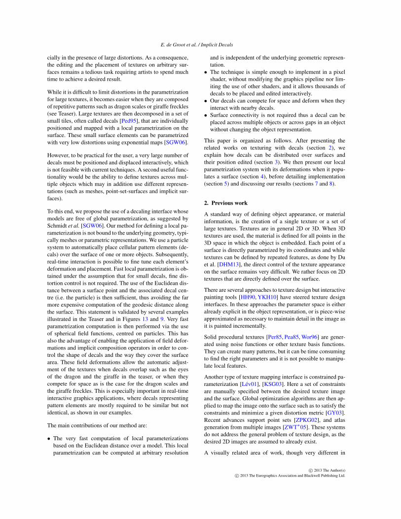
Decal placement consists of positioning particles over thesurface whose centre point will serve as centre for the fieldfunctions fi : R3 → [0,1] from which a local parametriza-tion is derived for the decal. Two strategies can be used:manual or automatic placement. Manual placement of par-ticles is done by selecting positions on the surface of themodel (see left image of Figure 1). Even though this aneasy task, it takes a long time to texture complex surfacesor surfaces that require a large number of decals. A tool toautomatically texture the whole surface greatly reduces themodelling time. With our texturing method such tools areeasily created. All our method needs for input is a list ofparticles (position, size and orientation). In our system thisinput is generated by scattering particles [WH94] onto thesurface of the model and have them repel each other. The ra-dius si of each particle is calculated by taking the maximumdistance to neighbouring particles in the local Delaunay tri-angulation. These local triangulations can be simply com-puted from the local Voronoi regions surrounding the par-ticle centres [Ben75, Tur91]. The orientation, i.e. local 2Dframe (ui,vi) ∈ [0,1]2 tangent to the surface and of originthe particle centre pi, is either random or aligned to somesurface field such as minimum or maximum curvature direc-tion fields [ACSD∗03,FJW∗05] or as done by Turk [Tur01].
Fleischer et al.’s Cellular Texture Generationwork [FLCB95] offers a method to generate seed lo-cations for our particles, evolving a system of partialdifferential equations to generate seed points and surface-based field values on object surfaces. We implemented asimplified version of this work, and instead of placing ageometric primitive at each particle, we place one of ourdecals.
The right image of Figure 1 shows 1000 decals distributed
c© 2013 The Author(s)c© 2013 The Eurographics Association and Blackwell Publishing Ltd.
E. de Groot et al. / Implicit Decals
Figure 1: Left:50 decals positioned manually in under a
minute. Right:1000 decals positioned using a particle sys-
tem.
over the surface of a model using a particle system. It shouldbe noted that the user can interactively edit the decals afterthe initial placement.
We use a particle system because it has the double advantageof being both easy to implement and flexible for integratingdecal editing operations. For example, after automaticallypositioning decals on a model, the user can interactively edita group of decals while the particle system repositions sur-rounding decals. For instance, particle position, orientationand radius can be directly modified and the system automat-ically and interactively adjusts the position of surroundingparticles. That way, textures can be translated over the sur-face, rotated and scaled. Instead of a particle system, remesh-ing algorithms [BPR∗06] could be used to generate a coarsemesh. The positions of the vertices of this mesh would bethe positions of the particles.
Once particles cover the surface, they are likely to overlapand in that case, a strategy has to be chosen in order to de-fine how the textures coming from each overlapping decalare combined. Different solutions can be adopted. One de-cal can be dominant and only its texture is applied, resultingin an overlapping feature (as the eye of the dragon in theteaser). Textures can be blended (blurred) as presented bySchmidt et al. [SGW06]. A new behavior, presented in thefollowing sections, is deformation in contact, which replacesoverlapping texture by texture deformations so that they arein contact but do not overlap. This generates useful resultsas those illustrated in the teaser and in Figure 9.
4. Local parametrization
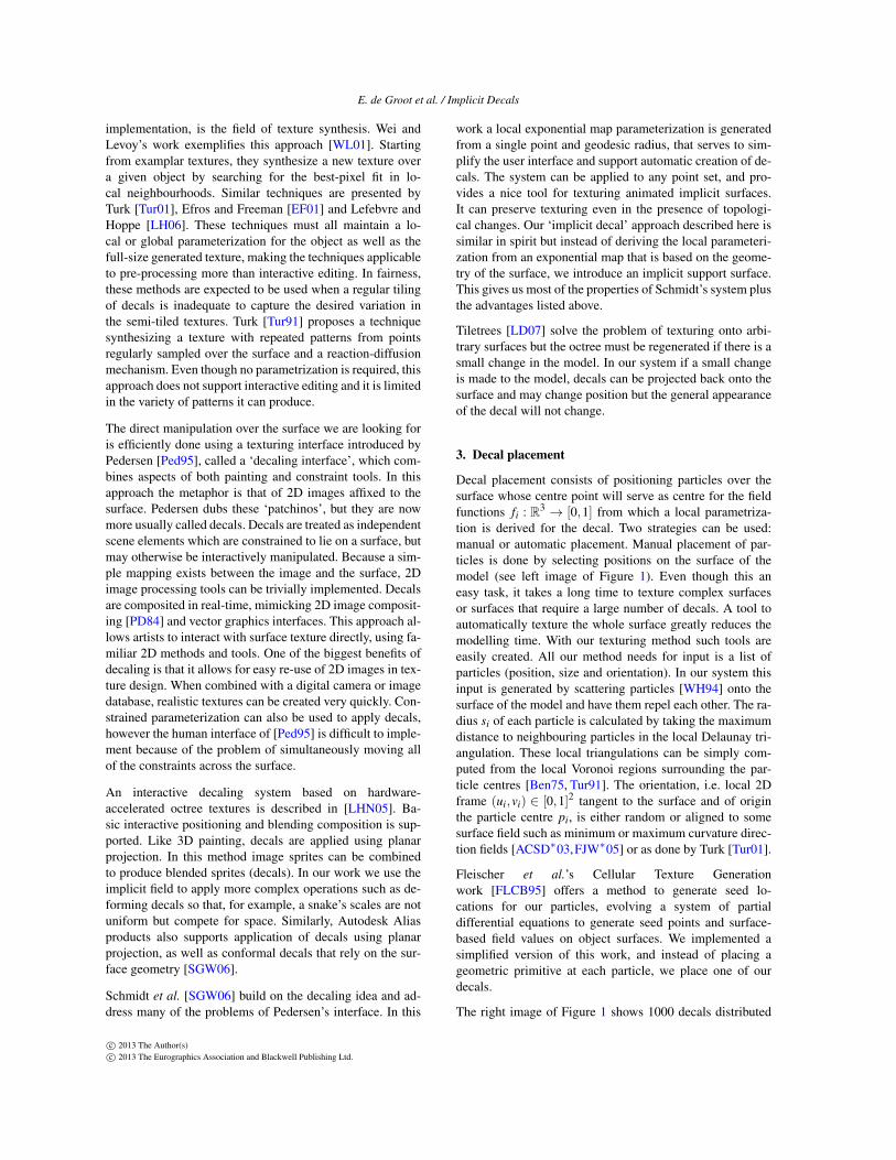
Once particles are distributed over the surface, we have asinput their centre pi, radius si and local frame (ui,vi) illus-trated in Figure 2 and computed as explained in Section 3.Particles centre pi and radius si are used to compute anisotropic spherical field functions fi : R3 → [0,1] which to-gether with the local frame (ui,vi) allows us to derive the lo-cal parametrization (section 4.1). Deformations produced bycontact between neighbouring decals are presented in sec-tion 4.2 and the way field functions can be modified to pro-duce parametrization adapted to decals of different shapes isexplained in section 4.3.
pi
vi
ui
si
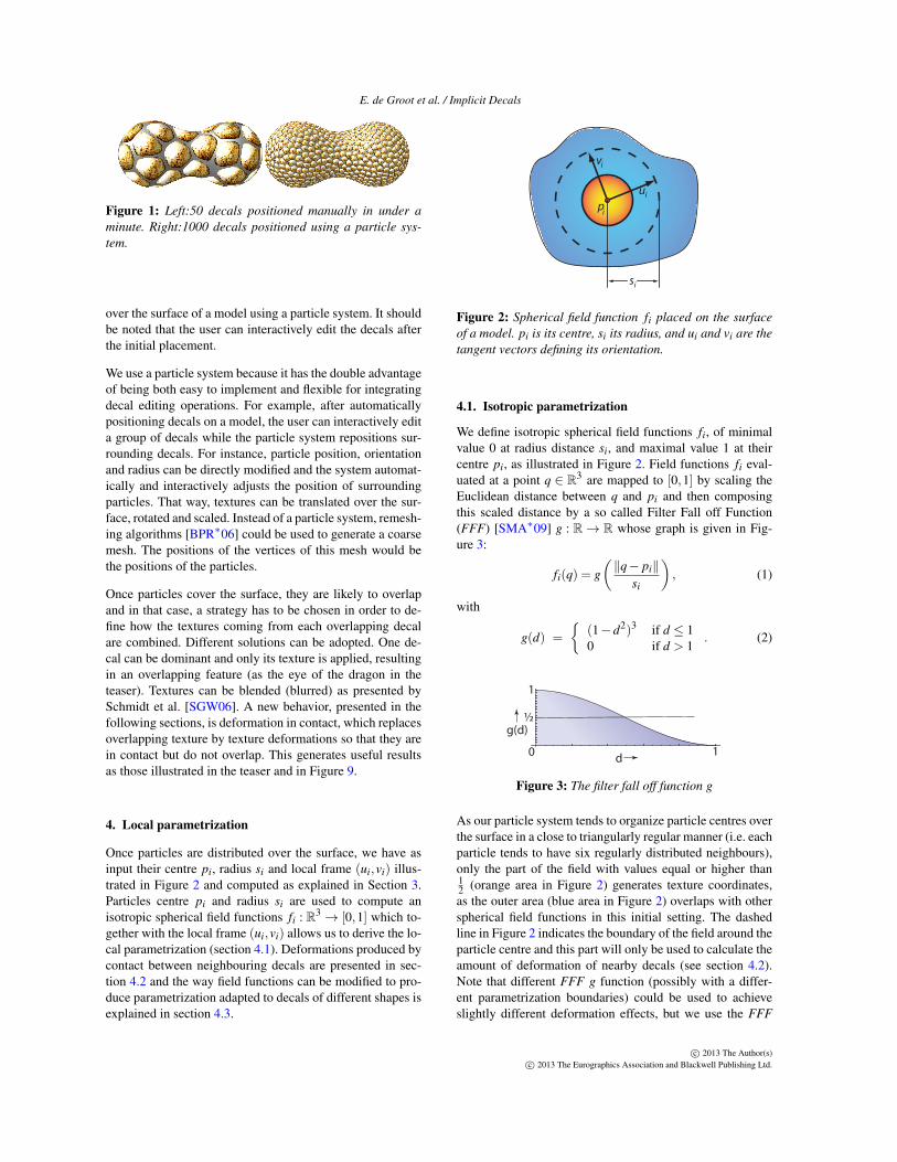
Figure 2: Spherical field function fi placed on the surface
of a model. pi is its centre, si its radius, and ui and vi are the
tangent vectors defining its orientation.
4.1. Isotropic parametrization
We define isotropic spherical field functions fi, of minimalvalue 0 at radius distance si, and maximal value 1 at theircentre pi, as illustrated in Figure 2. Field functions fi eval-uated at a point q ∈ R
3 are mapped to [0,1] by scaling theEuclidean distance between q and pi and then composingthis scaled distance by a so called Filter Fall off Function(FFF) [SMA∗09] g : R → R whose graph is given in Fig-ure 3:
fi(q) = g
(
‖q− pi‖
si
)
, (1)
with
g(d) =
{
(1−d2)3 if d ≤ 10 if d > 1
. (2)
d
g(d)
0
½
1
1
Figure 3: The filter fall off function g
As our particle system tends to organize particle centres overthe surface in a close to triangularly regular manner (i.e. eachparticle tends to have six regularly distributed neighbours),only the part of the field with values equal or higher than12 (orange area in Figure 2) generates texture coordinates,as the outer area (blue area in Figure 2) overlaps with otherspherical field functions in this initial setting. The dashedline in Figure 2 indicates the boundary of the field around theparticle centre and this part will only be used to calculate theamount of deformation of nearby decals (see section 4.2).Note that different FFF g function (possibly with a differ-ent parametrization boundaries) could be used to achieveslightly different deformation effects, but we use the FFF
c© 2013 The Author(s)c© 2013 The Eurographics Association and Blackwell Publishing Ltd.

E. de Groot et al. / Implicit Decals
from equation 1 for its high smoothness and its suitabilityfor contact deformations (see section 4.2).
From field function fi and the local frame (ui,vi) we derivethe local texture coordinates as a polar 2D coordinate system(r(q),θ(q)) as follows. To calculate the radius r(q) at a sur-face point q, we first evaluate the field value fi(q) to whichwe apply the inverse of g. We then scale it by g−1(1/2) toget the radius r(q) ∈ [0,1]:
r(q) =g−1 (F(q))
g−1(
12
) , (3)
where F = fi if only a single field function covers the pointq. We use equation 3 instead of the simpler scaled distance
r(q) =‖q−pi‖
siin order to support the different definition of
F presented in Section 4.2 where decals are deformed whenthey are in contact as illustrated in Figure 5.
Figure 4: Illustration of the local parametrization (left) on
a plane and (right) on a sphere.
The computation of the second texture coordinate θ(q) isperformed using the two perpendicular vectors ui and vi ofour local frame. If q∗ is the projection of q onto the planeformed by ui and vi, the value of θ(q) is the angle betweenui and the vector (q∗− pi):
θ(q) = arctan
(
vi · (q− pi)
ui · (q− pi)
)
. (4)
Figure 4 shows an example of a our local parametrization ona plane and on a sphere. The vectors ui and vi are calculatedfrom the surface normal at pi (using cross product) and auser defined orientation angle.
4.2. Contact deformations
When decals are in collision, overlapping is avoided andcontact decal deformations are performed as illustrated inFigure 5. As our local parametrization is directly derivedfrom field functions fi : R3 → [0,1], they support the set op-erators produced for combining implicit surfaces defined bycompactly supported field functions [Blo97].
We need a deformation modelling contact between n fieldfunctions, avoiding gaps and discontinuities while maintain-ing r in [0,1] with r(q) = 1 for all surface point q in the de-formed field function boundary (see Figure 5). Following the
Figure 5: A decal (left) placed on a sphere once, twice and
three times
procedure suggested by Cani [Can93], we compute a fieldfunction F as a deformation of the function fk having thehighest field value at a point q:
F(q) =12+
(
fk(q)−12
)
∏j 6=k
h(
f j(q), fk(q))
, (5)
where
h(s, t) =
1−(
s+t−12s−1
)1
1−tif s+ t ≥ 1
1 if s+ t < 1.
In this formulation, when a point q only lies in the field ofone field function, the product part of equation 5 yields 1and the whole equation equals fi. When other field func-tions overlap in q, equation 5 adapts fi(q) to make the decaltouch but not overlap the nearby decals. This behavior is ob-tained when function F reproduces the graph presented inFigure 7, illustrating the combination of two field functions(including contact). This graph has been constructed follow-ing the properties and the procedures presented by Barthe etal. [BWdG04], Bernhardt et al. [BBCW10] and Gourmel etal. [GBC∗13]. Even though several equations matching thisgraph could be proposed, our formulation has the advantageof being both n-ary, i.e. it is able to combine any number ofdecals at once, and efficient to compute.
A B C D
I
I
III
IVII II
I
Figure 6: 4 possible situations when using only 2 decals
Equation 5 can be understood by looking at the interactionsbetween two field functions, f0 and f1, illustrated in Fig-ure 6. Four situations are to be considered. In situation A,
c© 2013 The Author(s)c© 2013 The Eurographics Association and Blackwell Publishing Ltd.

E. de Groot et al. / Implicit Decals
the fields are not overlapping each other and no deformationis needed. In situation B and C, the fields are overlappingbut the parametrized areas are not, so again, no deformationis needed. Only in situation D where the parametrized areasoverlap, is deformation required.
0
½
1
1½
f (q)0
f (q)1
I
III IV
II
Figure 7: Graph of our function F when two field functions
are involved. Field functions f1 and f0 give the values for
respectively the abscissa and the ordinate.
The different areas numbered from I to IV in which the finalfunction F is computed with a specific expected result areillustrated in Figure 7. In this figure, the values of functionf1 are taken as abscissa and those of function f0 as ordi-nate. On the upper-left part of the diagonal line f0 = f1, thefield function with the highest value is f0 and F is the re-sult of the deformation of f0 while in the lower-right part ofthis line, the highest value is the one of f1 and F is the re-sult of its deformation. As we expect the same deformationbehavior on both decals, the one parametrized from f0 andthe one parametrized from f1, these two parts are symmet-ric and we propose to only focus on the upper-left part. Theblack lines in Figure 7 are the iso-lines of the resulting decalfor F = 1
10 , F = 210 , etc. Where these iso-lines are horizon-
tal, it means that they reproduce the values of f0, F = f0and no deformation is performed. Otherwise, they representthe way the iso-values of f0 are deformed by F , i.e. the waythe decal is deformed. The contact is where f0 = f1 and wesee in red area of Figure 7 how the function F deforms theiso-curves at its vicinity. We refer to the implicit extrusionfields [BGC01] for a detailed explanation of how to link thegraph of the composition operator (here function F) with thedeformed objects (here the decals).
In other words, no deformation is to be performed in situa-tions A, B and C (Figure 6), which is guaranteed as in areasI and II, F = f0. In fact, deformation must hold in areas thatonly exist in situation D, which correspond to areas III andIV. These areas are where contact and field deformations arethus to be performed. Formally, they correspond to field val-ues where f0(q) + f1(q) > 1. In area IV, contact deforma-tions at parametrization boundaries are performed by ensur-
ing that if f0 = f1, then F = 12 . The rest of area IV and area
III are used to build a function F performing smooth fielddeformations between the contact at boundaries and areas Iand II where no deformation are required.
The resulting deformation in contact performed on ourparametrization when this definition of F is used in equa-tion 3 is illustrated with two and three field functions in Fig-ure 5.
4.3. Anisotropic parametrization
Non-circular decals are easily supported by slightly adapt-ing the technique presented in [BS95]. In the computationof the field function in equation 1, rather than scaling theEuclidean distance between a point q and the particle centrepi with a constant radius si, this distance is scaled by the dis-tance between pi and the point bi(q) of intersection of a raylaunched from pi and the decal boundary (see Figure 8-left).This scaling is done so that for all point q lying on the decalboundary, fi(q) =
12 .
fi(q) = g
(
‖q− pi‖
bi(q)
)
g−1
(
12
)
. (6)
Figure 8: Storing the field function fi in a 2D texture for the
puzzle piece decal. Left: computing bi. Right: the field values
in the texture (the yellow line marks the 12 contour).
In this case, function fi can be directly precomputed andstored in a 2D texture (Figure 8-right) or computed from ananalytical function bi : R2 → R
+ giving the radial distancebetween the decal centre and its boundary for all point q.
The puzzle piece used in Figure 8 is mapped on the bunny inFigure 9 along with some other non-circular decals.
5. Implementation
Implicit decals require texture mapping on a per-pixel ba-sis which can be done in pixel shaders. The definition ofdecals by 3D field functions allows a computation of thepixel colour using only its 3D coordinates as input (as for 3Dtextures). The requirement for an efficient evaluation is thefast access to decals enclosing the pixel. Once this is done,contact deformation, overlapping or any invertible transfor-mation can be applied to derive the texture coordinates andcompute the final material information. In our system the
c© 2013 The Author(s)c© 2013 The Eurographics Association and Blackwell Publishing Ltd.

E. de Groot et al. / Implicit Decals
Figure 9: 3 models textured using Implicit Decals: the knot, implicit spheres, and the bunny
pixel shader of the GPU is used, because it can achieve in-teractive frame rates. To render a number of implicit decalson the surface of a model, the decal information (position,size and tangent vectors) is loaded into the graphics cardmemory. The pixel shader program queries the decal infor-mation to calculate texture coordinates. To increase perfor-mance and allow a large number of decals to be rendered,we implemented an octree structure similar to the one de-scribed in [LHN05]. An octree data structure as describedin [LSK∗06] could also be used.
Before the decals are loaded into the GPU memory, an octreeis constructed containing the decals. Each non empty voxelcontains either 8 references to other voxels or a maximum of8 references to decals that intersect with the voxel. A voxelis subdivided when it overlaps with more than 8 decals. Thelist of voxels is loaded into GPU memory together with thelist of decals. Our implementation of the pixel shader con-tains an octree lookup function which typically uses between4 and 10 repetitions to traverse the octree and retrieve theneeded voxel from the octree. With this implementation thepixel shader performs a maximum of 10 octree lookup rep-etitions and includes a maximum of 8 decals in the calcula-tion of the final texture coordinates. Without an octree, alldecals would have to be included in the calculation of the fi-nal texture coordinates This would greatly increase compu-tation times and at present would limit the maximum numberof decals to approximately 20 (in a single pass) due to GPUlimitations.
Decals can be removed from the octree by removing themfrom the decal list in the GPU memory. Adding and moving
decals however, would normally require a new constructionof the octree. To prevent rebuilding the octree while the useris editing a small set of decals, the pixel shader implemen-tation allows for a small number of decals to be added inaddition to the ones in the octree. These decals will alwaysbe included in the calculation of the final texture coordinates.Rebuilding the octree will only be necessary when the userstarts editing (adding, removing, moving) a different set ofdecals. After the rebuild (which usually is nearly instant, butcan take up to a second when thousands of decals are used),editing operations can be performed interactively.
6. Filtering
Figure 10: Filtering at different resolutions. Top row:
standard Mipmaps and anisotropic filtering. Bottom row:
adapted Mipmaps and anisotropic filtering.
In general, existing techniques like trilinear or anisotropic
c© 2013 The Author(s)c© 2013 The Eurographics Association and Blackwell Publishing Ltd.
E. de Groot et al. / Implicit Decals
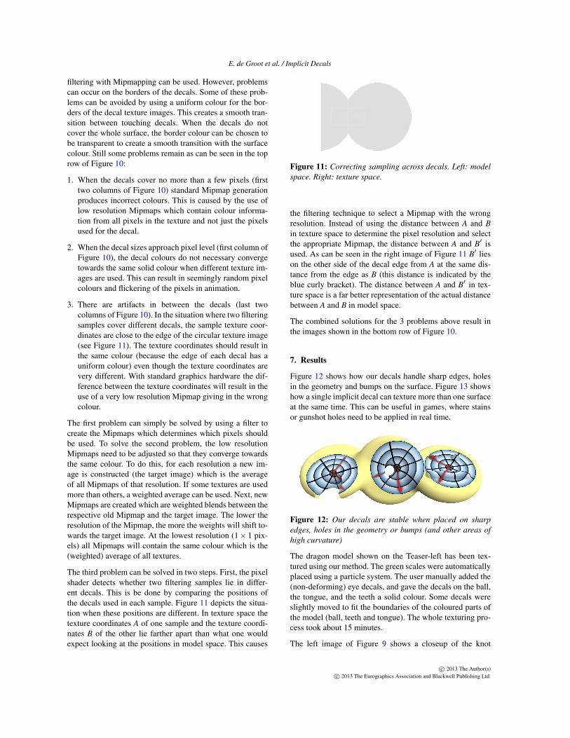
filtering with Mipmapping can be used. However, problemscan occur on the borders of the decals. Some of these prob-lems can be avoided by using a uniform colour for the bor-ders of the decal texture images. This creates a smooth tran-sition between touching decals. When the decals do notcover the whole surface, the border colour can be chosen tobe transparent to create a smooth transition with the surfacecolour. Still some problems remain as can be seen in the toprow of Figure 10:
1. When the decals cover no more than a few pixels (firsttwo columns of Figure 10) standard Mipmap generationproduces incorrect colours. This is caused by the use oflow resolution Mipmaps which contain colour informa-tion from all pixels in the texture and not just the pixelsused for the decal.
2. When the decal sizes approach pixel level (first column ofFigure 10), the decal colours do not necessary convergetowards the same solid colour when different texture im-ages are used. This can result in seemingly random pixelcolours and flickering of the pixels in animation.
3. There are artifacts in between the decals (last twocolumns of Figure 10). In the situation where two filteringsamples cover different decals, the sample texture coor-dinates are close to the edge of the circular texture image(see Figure 11). The texture coordinates should result inthe same colour (because the edge of each decal has auniform colour) even though the texture coordinates arevery different. With standard graphics hardware the dif-ference between the texture coordinates will result in theuse of a very low resolution Mipmap giving in the wrongcolour.
The first problem can simply be solved by using a filter tocreate the Mipmaps which determines which pixels shouldbe used. To solve the second problem, the low resolutionMipmaps need to be adjusted so that they converge towardsthe same colour. To do this, for each resolution a new im-age is constructed (the target image) which is the averageof all Mipmaps of that resolution. If some textures are usedmore than others, a weighted average can be used. Next, newMipmaps are created which are weighted blends between therespective old Mipmap and the target image. The lower theresolution of the Mipmap, the more the weights will shift to-wards the target image. At the lowest resolution (1× 1 pix-els) all Mipmaps will contain the same colour which is the(weighted) average of all textures.
The third problem can be solved in two steps. First, the pixelshader detects whether two filtering samples lie in differ-ent decals. This is be done by comparing the positions ofthe decals used in each sample. Figure 11 depicts the situa-tion when these positions are different. In texture space thetexture coordinates A of one sample and the texture coordi-nates B of the other lie farther apart than what one wouldexpect looking at the positions in model space. This causes
{{
{ {A B
A
B
B’
A’
{{
Figure 11: Correcting sampling across decals. Left: model
space. Right: texture space.
the filtering technique to select a Mipmap with the wrongresolution. Instead of using the distance between A and B
in texture space to determine the pixel resolution and selectthe appropriate Mipmap, the distance between A and B′ isused. As can be seen in the right image of Figure 11 B′ lieson the other side of the decal edge from A at the same dis-tance from the edge as B (this distance is indicated by theblue curly bracket). The distance between A and B′ in tex-ture space is a far better representation of the actual distancebetween A and B in model space.
The combined solutions for the 3 problems above result inthe images shown in the bottom row of Figure 10.
7. Results
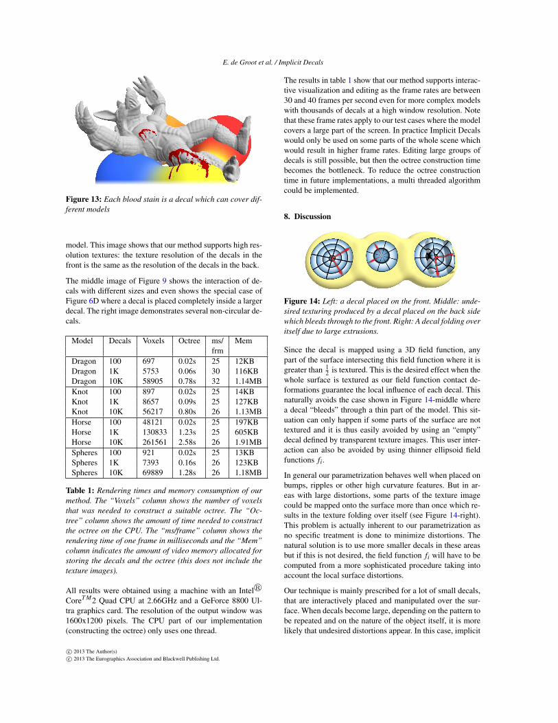
Figure 12 shows how our decals handle sharp edges, holesin the geometry and bumps on the surface. Figure 13 showshow a single implicit decal can texture more than one surfaceat the same time. This can be useful in games, where stainsor gunshot holes need to be applied in real time.
Figure 12: Our decals are stable when placed on sharp
edges, holes in the geometry or bumps (and other areas of
high curvature)
The dragon model shown on the Teaser-left has been tex-tured using our method. The green scales were automaticallyplaced using a particle system. The user manually added the(non-deforming) eye decals, and gave the decals on the ball,the tongue, and the teeth a solid colour. Some decals wereslightly moved to fit the boundaries of the coloured parts ofthe model (ball, teeth and tongue). The whole texturing pro-cess took about 15 minutes.
The left image of Figure 9 shows a closeup of the knot
c© 2013 The Author(s)c© 2013 The Eurographics Association and Blackwell Publishing Ltd.
E. de Groot et al. / Implicit Decals
Figure 13: Each blood stain is a decal which can cover dif-
ferent models
model. This image shows that our method supports high res-olution textures: the texture resolution of the decals in thefront is the same as the resolution of the decals in the back.
The middle image of Figure 9 shows the interaction of de-cals with different sizes and even shows the special case ofFigure 6D where a decal is placed completely inside a largerdecal. The right image demonstrates several non-circular de-cals.
Model Decals Voxels Octree ms/ Memfrm
Dragon 100 697 0.02s 25 12KBDragon 1K 5753 0.06s 30 116KBDragon 10K 58905 0.78s 32 1.14MBKnot 100 897 0.02s 25 14KBKnot 1K 8657 0.09s 25 127KBKnot 10K 56217 0.80s 26 1.13MBHorse 100 48121 0.02s 25 197KBHorse 1K 130833 1.23s 25 605KBHorse 10K 261561 2.58s 26 1.91MBSpheres 100 921 0.02s 25 13KBSpheres 1K 7393 0.16s 26 123KBSpheres 10K 69889 1.28s 26 1.18MB
Table 1: Rendering times and memory consumption of our
method. The “Voxels” column shows the number of voxels
that was needed to construct a suitable octree. The “Oc-
tree” column shows the amount of time needed to construct
the octree on the CPU. The “ms/frame” column shows the
rendering time of one frame in milliseconds and the “Mem”
column indicates the amount of video memory allocated for
storing the decals and the octree (this does not include the
texture images).
All results were obtained using a machine with an Intelr
CoreT M2 Quad CPU at 2.66GHz and a GeForce 8800 Ul-tra graphics card. The resolution of the output window was1600x1200 pixels. The CPU part of our implementation(constructing the octree) only uses one thread.
The results in table 1 show that our method supports interac-tive visualization and editing as the frame rates are between30 and 40 frames per second even for more complex modelswith thousands of decals at a high window resolution. Notethat these frame rates apply to our test cases where the modelcovers a large part of the screen. In practice Implicit Decalswould only be used on some parts of the whole scene whichwould result in higher frame rates. Editing large groups ofdecals is still possible, but then the octree construction timebecomes the bottleneck. To reduce the octree constructiontime in future implementations, a multi threaded algorithmcould be implemented.
8. Discussion
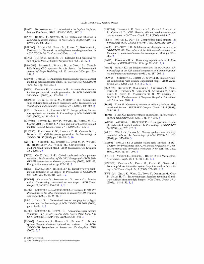
Figure 14: Left: a decal placed on the front. Middle: unde-
sired texturing produced by a decal placed on the back side
which bleeds through to the front. Right: A decal folding over
itself due to large extrusions.
Since the decal is mapped using a 3D field function, anypart of the surface intersecting this field function where it isgreater than 1
2 is textured. This is the desired effect when thewhole surface is textured as our field function contact de-formations guarantee the local influence of each decal. Thisnaturally avoids the case shown in Figure 14-middle wherea decal “bleeds” through a thin part of the model. This sit-uation can only happen if some parts of the surface are nottextured and it is thus easily avoided by using an “empty”decal defined by transparent texture images. This user inter-action can also be avoided by using thinner ellipsoid fieldfunctions fi.
In general our parametrization behaves well when placed onbumps, ripples or other high curvature features. But in ar-eas with large distortions, some parts of the texture imagecould be mapped onto the surface more than once which re-sults in the texture folding over itself (see Figure 14-right).This problem is actually inherent to our parametrization asno specific treatment is done to minimize distortions. Thenatural solution is to use more smaller decals in these areasbut if this is not desired, the field function fi will have to becomputed from a more sophisticated procedure taking intoaccount the local surface distortions.
Our technique is mainly prescribed for a lot of small decals,that are interactively placed and manipulated over the sur-face. When decals become large, depending on the pattern tobe repeated and on the nature of the object itself, it is morelikely that undesired distortions appear. In this case, implicit
c© 2013 The Author(s)c© 2013 The Eurographics Association and Blackwell Publishing Ltd.

E. de Groot et al. / Implicit Decals
decals may fail to provide a satisfactory result and it wouldbe better to use a more elaborate technique such as the decalsproposed by Schmidt et al. [SGW06].
It is also difficult to maintain a consistent surface covering ifit is animated. Decals may change of shape and gaps may ap-pear. The texturing of dynamic objects with implicit decalsremains an open problem.
Current graphics hardware still limits the number of de-cals that can be edited simultaneously to approximately 20.When small groups of decals are being edited, they will beremoved from the octree and added to the list of editable de-cals. The octree needs to be recomputed whenever the num-ber of decals in this list exceeds the hardware limit. When tenthousands of decals are used, this can result in an occasionaldelay of approximately one second (see table 1). Editing op-erations that involve large groups of decals, always requirethe octree to be rebuild and will be significantly slower.
9. Conclusion and Future Work
The main contribution of this research is an efficient methodfor placing and editing surface decals that can interact withone another. The surface does not require an existing param-eterization. Since the method lends itself to implementationon the GPU, thousands of decals can be placed and edited.Traditional techniques would require excessively large tex-tures to achieve a reasonable resolution, making these tech-niques infeasible for real-time applications.
An earlier decaling method [SGW06] uses an arc length ap-proximation (exponential map) to find a local parameteriza-tion on the surface, whereas our method uses an implicit fieldthat is independent of the geometry. Our implicit techniquehas several advantages demonstrated in section 7:
• Implicit decals are independent of the underlying geome-try making them applicable to multi-resolution meshes.
• The bulk of the computations can be done in the pixelshader making interactive editing of thousands of decalspossible.
• Contact deformation can be used to make the decals ap-pear to compete for space.
• An implicit decal can be made to span several objectswithout duplicating the decal or merging the objects.
Our method is similar to Cellular Texture Genera-tion [FLCB95], in which a geometric primitive is placed ateach particle, whereas we place a texture primitive instead.In this way many similar effects can be achieved, but at low-cost in a pixel shader. As future work, we could couple ourimplicit decals with a GPU-shader based displacement mapmethod, to allow for a large set of Fleischer et al.’s imagesto be generated in hardware.
Section 4.2 shows how contact deformation can be used toshape the decals. Future work includes investigating howother implicit operations like blending can be used to achieve
different effects. Also, different distance metrics like man-hattan or anisotropic distance could be used to produce awider variety of results.
A larger number of patterns could also be generated by creat-ing two or more layers of decals. The final pattern is createdby combining the layers, for example by using transparencyto uncover deeper layers or some other function which com-bines the colours of each layer. Future work can also includedesigning functions to combine layers; how should layers bepositioned in relation to each other to create interesting pat-terns.
To incorporate implicit decals more easily into existing mod-elling systems, a conversion between an implicit decal tex-ture and more conventional textures can be written. When anatlas is in place, the model space positions of each texel ofthe atlas can simply be evaluated to get the correspondingcolours. Future research can be done to create converters forother texture systems and incorporate better filtering.
Other future work includes better tools for decal position-ing and editing. If a Poisson-disk sampling method [DH06]could be adapted to curved closed surfaces of any topology,this would significantly reduce the computation time of aninitial decal distribution. Also, the system would greatly ben-efit from editing tools like a decal spray paint tool and brushtools that change the size or orientation of the decals. Au-tomatic determination of the orientation of the decals couldbe done by using the gradient field or other properties ofthe model. Finally, decals with different behaviours could beadded. For example decals which deform other decals, butdo not deform themselves.
Acknowledgments
This work has been partially funded by NSERC (the NaturalScience and Engineering Research Council of Canada), theRoyal Society, Uk, Intel (Canada) and the IM&M project(ANR-11-JS02-007). We are grateful for the support of theAmerican University of Beirut for Ahmad Nasri’s sabbaticalleave to the University of Calgary.
References
[ACSD∗03] ALLIEZ P., COHEN-STEINER D., DEVILLERS O.,LÉVY B., DESBRUN M.: Anisotropic polygonal remeshing.ACM Trans. Graph. 22, 3 (July 2003), 485–493. 3
[BBCW10] BERNHARDT A., BARTHE L., CANI M.-P.,WYVILL B.: Implicit blending revisited. Comput. Graph. Forum
29, 2 (May 2010), 367–375. 5
[Ben75] BENTLEY J. L.: Multidimensional binary search treesused for associative searching. Commun. ACM 18, 9 (1975), 509–517. 3
[BGC01] BARTHE L., GAILDRAT V., CAUBET R.: Extrusion of1D implicit profiles: Theory and first application. International
Journal of Shape Modeling 7 (2001), 179–199. 6
c© 2013 The Author(s)c© 2013 The Eurographics Association and Blackwell Publishing Ltd.
E. de Groot et al. / Implicit Decals
[Blo97] BLOOMENTHAL J.: Introduction to Implicit Surfaces.Morgan Kaufmann, ISBN 1-55860-233-X, 1997. 5
[BN76] BLINN J. F., NEWELL M. E.: Texture and reflection incomputer generated images. In Proceedings of SIGGRAPH ’76
(1976), pp. 266–266. 1
[BPR∗06] BOTSCH M., PAULY M., ROSSL C., BISCHOFF S.,KOBBELT L.: Geometric modeling based on triangle meshes. InACM SIGGRAPH ’06 Courses (2006), p. 1. 4
[BS95] BLANC C., SCHLICK C.: Extended field functions forsoft objects. Proc. of Implicit Surfaces’95 (1995), 21–32. 6
[BWdG04] BARTHE L., WYVILL B., DE GROOT E.: Control-lable binary CSG operators for soft objects. In International
Journal of Shape Modeling, vol. 10. december 2004, pp. 135–154. 5
[Can93] CANI M.-P.: An implicit formulation for precise contactmodeling between flexible solids. In Proceedings of SIGGRAPH
’93 (1993), pp. 313–320. 5
[DH06] DUNBAR D., HUMPHREYS G.: A spatial data structurefor fast poisson-disk sample generation. In ACM SIGGRAPH
2006 Papers (2006), pp. 503–508. 10
[DHM13] DU S.-P., HU S.-M., MARTIN R. R.: Semiregularsolid texturing from 2d image exemplars. IEEE Transactions on
Visualization and Computer Graphics 19, 3 (2013), 460–469. 2
[EF01] EFROS A. A., FREEMAN W. T.: Image quilting for tex-ture synthesis and transfer. In Proceedings of ACM SIGGRAPH
2001 (2001), pp. 341–348. 3
[FJW∗05] FOSTER K., JEPP P., WYVILL B., SOUSA M. C.,GALBRAITH C., JORGE J. A.: Pen-and-ink for blobtree implicitmodels. Comput. Graph. Forum 24, 3 (2005), 267–276. 3
[FLCB95] FLEISCHER K. W., LAIDLAW D. H., CURRIN B. L.,BARR A. H.: Cellular texture generation. In Proceedings of
SIGGRAPH ’95 (1995), pp. 239–248. 3, 10
[GBC∗13] GOURMEL O., BARTHE L., CANI M.-P., WYVILL
B., BERNHARDT A., PAULIN M., GRASBERGER H.: Agradient-based implicit blend. ACM Transactions on Graphics
32, 2 (2013). 5
[GY03] GU X., YAU S.-T.: Global conformal surface parame-terization. In Proceedings of the 2003 Eurographics/ACM SIG-
GRAPH symposium on Geometry processing (2003), SGP ’03,Eurographics Association, pp. 127–137. 2
[HH90] HANRAHAN P., HAEBERLI P. E.: Direct wysiwyg paint-ing and texturing on 3d shapes. In Proceedings of SIGGRAPH
90 (1990), vol. 24, pp. 215–223. 1, 2
[KSG03] KRAEVOY V., SHEFFER A., GOTSMAN C.: Match-maker: Constructing constrained texture maps. ACM Trans.
Graph. 22, 3 (2003), 326–333. 1, 2
[LD07] LEFEBVRE S., DACHSBACHER C.: Tiletrees. In I3D ’07:
Proceedings of the 2007 symposium on Interactive 3D graphics
and games (2007), pp. 25–31. 3
[Lév01] LÉVY B.: Constrained texture mapping for polygo-nal meshes. In Proceedings of ACM SIGGRAPH 2001 (2001),pp. 417–424. 1, 2
[LH06] LEFEBVRE S., HOPPE H.: Appearance-space texturesynthesis. In ACM SIGGRAPH 2006 Papers (New York, NY,USA, 2006), SIGGRAPH ’06, ACM, pp. 541–548. 3
[LHN05] LEFEBVRE S., HORNUS S., NEYRET F.: Texturesprites: Texture elements splatted on surfaces. In ACM-
SIGGRAPH Symposium on Interactive 3D Graphics (I3D)
(2005). 3, 7
[LSK∗06] LEFOHN A. E., SENGUPTA S., KNISS J., STRZODKA
R., OWENS J. D.: Glift: Generic, efficient, random-access gpudata structures. ACM Trans. Graph. 25, 1 (2006), 60–99. 7
[PD84] PORTER T., DUFF T.: Compositing digital images. InProceedings of SIGGRAPH 84 (1984), vol. 18, pp. 253–259. 3
[Pea85] PEACHEY D. R.: Solid texturing of complex surfaces. InSIGGRAPH ’85: Proceedings of the 12th annual conference on
Computer graphics and interactive techniques (1985), pp. 279–286. 2
[Ped95] PEDERSEN H. K.: Decorating implicit surfaces. In Pro-
ceedings of SIGGRAPH 95 (1995), pp. 291–300. 2, 3
[Per85] PERLIN K.: An image synthesizer. In SIGGRAPH ’85:
Proceedings of the 12th annual conference on Computer graph-
ics and interactive techniques (1985), pp. 287–296. 2
[SGW06] SCHMIDT R., GRIMM C., WYVILL B.: Interactive de-cal compositing with discrete exponential maps. ACM Trans.
Graph. 25, 3 (2006), 605–613. 2, 3, 4, 10
[SMA∗09] SHIRLEY P., MARSHNER S., ASHIKHMIN M., GLE-ICHER M., HOFFMAN N., JOHNSON G., MUNZNER T., REIN-HARD E., SUNG K., THOMPSON W. B., WILLEMSEN P.,WYVILL B.: Fundamentals of Computer Graphics, 3rd edition.AK Peters, June 2009. 4
[Tur91] TURK G.: Generating textures on arbitrary surfaces usingreaction-diffusion. SIGGRAPH Comput. Graph. 25, 4 (1991),289–298. 3
[Tur01] TURK G.: Texture synthesis on surfaces. In Proceedings
of ACM SIGGRAPH 2001 (2001), pp. 347–354. 3
[WH94] WITKIN A. P., HECKBERT P. S.: Using particles to sam-ple and control implicit surfaces. In Proceedings of SIGGRAPH
’94 (1994), pp. 269–277. 3
[WL01] WEI L.-Y., LEVOY M.: Texture synthesis over arbitrarymanifold surfaces. In Proceedings of ACM SIGGRAPH 2001
(2001), pp. 355–360. 3
[Wor96] WORLEY S.: A cellular texture basis function. In SIG-
GRAPH ’96: Proceedings of the 23rd annual conference on Com-
puter graphics and interactive techniques (New York, NY, USA,1996), ACM, pp. 291–294. 2
[YKH10] YUKSEL C., KEYSER J., HOUSE D. H.: Mesh colors.ACM Trans. Graph. 29, 2 (2010), 1–11. 1, 2
[ZPKG02] ZWICKER M., PAULY M., KNOLL O., GROSS M.:Pointshop 3d: An interactive system for point-based surface edit-ing. ACM Trans. Graph. 21, 3 (2002), 322–329. 1, 2
[ZWT∗05] ZHOU K., WANG X., TONG Y., DESBRUN M., GUO
B., SHUM H.-Y.: Texturemontage: Seamless texturing of arbi-trary surfaces from multiple images. ACM Trans. Graph. 24, 3(2005), 1148–1155. 1, 2
c© 2013 The Author(s)c© 2013 The Eurographics Association and Blackwell Publishing Ltd.