implementing iso 17025 measurement uncertainty ... · pdf file3 fluke calibration implementing...
TRANSCRIPT
Application Note
F r o m t h e F l u k e C a l i b r a t i o n D i g i t a l L i b r a r y @ w w w. f l u k e c a l . c o m / l i b r a r y
Implementing ISO 17025 Measurement Uncertainty Requirements in Software
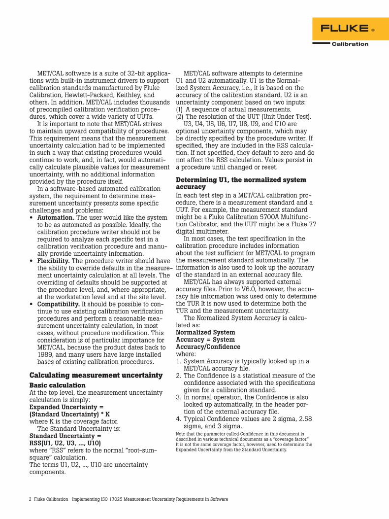
IntroductionThere is an increasing need to determine measurement uncertainties in a calibration envi-ronment. This need is based on the requirement to comply with certain standards documents, such as ISO 17025. It is no longer sufficient to calculate the traditional test uncertainty ratio (TUR), per MIL STD 45662. The TUR is usually calculated as:TUR = (Test Tolerance) / (Accuracy of Standard)
The TUR calculation is based on the stated accuracy of the measurement standard, but it does not represent the total measurement uncer-tainty, because it does not encompass empirical information based on a sequence of actual mea-surements. Nor does it incorporate measurement uncertainty information based on the resolution of the Unit Under Test (UUT) or other components of the measurement system and aspects of the measurement environment.
MET/CAL is a software product, part of the MET/CAL® Plus suite of applications produced by Fluke Calibration. MET/CAL was first released in 1989 as an MS-DOS-based product. The initial release of MET/CAL coincided with the introduc-tion of the Fluke Calibration 5700A Multifunction Calibrator. Subsequently, MET/CAL was ported to the Microsoft Windows® environment (V4.0), and integrated with Fluke Calibration’s MET/TRACK® asset management software (V5.0).
ISO/DIS 17025, “General Requirements for the Competence of Testing and Calibration Laboratories,” states that “calibration certificates shall contain the measurement results including the measurement uncertainty.” What does that mean? Is it simply a Test Uncertainty Ratio (TUR) calculation, or are there other factors involved? Using the “Guide to the Expression of Uncertainty in Measurement,” it certainly is more than a TUR calculation. This application note describes the implementa-tion of the measurement uncertainty calculation in the Fluke Calibration MET/CAL® automated calibration software pack-age. Compliance with ISO/DIS 17025 is discussed.
2 Fluke Calibration Implementing ISO 17025 Measurement Uncertainty Requirements in Software
MET/CAL software is a suite of 32-bit applica-tions with built-in instrument drivers to support calibration standards manufactured by Fluke Calibration, Hewlett-Packard, Keithley, and others. In addition, MET/CAL includes thousands of precompiled calibration verification proce-dures, which cover a wide variety of UUTs.
It is important to note that MET/CAL strives to maintain upward compatibility of procedures. This requirement means that the measurement uncertainty calculation had to be implemented in such a way that existing procedures would continue to work, and, in fact, would automati-cally calculate plausible values for measurement uncertainty, with no additional information provided by the procedure itself.
In a software-based automated calibration system, the requirement to determine mea-surement uncertainty presents some specific challenges and problems:• Automation. The user would like the system
to be as automated as possible. Ideally, the calibration procedure writer should not be required to analyze each specific test in a calibration verification procedure and manu-ally provide uncertainty information.
• Flexibility. The procedure writer should have the ability to override defaults in the measure-ment uncertainty calculation at all levels. The overriding of defaults should be supported at the procedure level, and, where appropriate, at the workstation level and at the site level.
• Compatibility. It should be possible to con-tinue to use existing calibration verification procedures and perform a reasonable mea-surement uncertainty calculation, in most cases, without procedure modification. This consideration is of particular importance for MET/CAL, because the product dates back to 1989, and many users have large installed bases of existing calibration procedures.
Calculating measurement uncertaintyBasic calculationAt the top level, the measurement uncertainty calculation is simply:Expanded Uncertainty = (Standard Uncertainty) * Kwhere K is the coverage factor.
The Standard Uncertainty is:Standard Uncertainty = RSS(U1, U2, U3, ..., U10)where “RSS” refers to the normal “root-sum-square” calculation.The terms U1, U2, ..., U10 are uncertainty components.
MET/CAL software attempts to determine U1 and U2 automatically. U1 is the Normal-ized System Accuracy, i.e., it is based on the accuracy of the calibration standard. U2 is an uncertainty component based on two inputs:(1) A sequence of actual measurements.(2) The resolution of the UUT (Unit Under Test).
U3, U4, U5, U6, U7, U8, U9, and U10 are optional uncertainty components, which may be directly specified by the procedure writer. If specified, they are included in the RSS calcula-tion. If not specified, they default to zero and do not affect the RSS calculation. Values persist in a procedure until changed or reset.
Determining U1, the normalized system accuracyIn each test step in a MET/CAL calibration pro-cedure, there is a measurement standard and a UUT. For example, the measurement standard might be a Fluke Calibration 5700A Multifunc-tion Calibrator, and the UUT might be a Fluke 77 digital multimeter.
In most cases, the test specification in the calibration procedure includes information about the test sufficient for MET/CAL to program the measurement standard automatically. The information is also used to look up the accuracy of the standard in an external accuracy file.
MET/CAL has always supported external accuracy files. Prior to V6.0, however, the accu-racy file information was used only to determine the TUR It is now used to determine both the TUR and the measurement uncertainty.
The Normalized System Accuracy is calcu-lated as:Normalized System Accuracy = System Accuracy/Confidencewhere:1. System Accuracy is typically looked up in a
MET/CAL accuracy file.2. The Confidence is a statistical measure of the
confidence associated with the specifications given for a calibration standard.
3. In normal operation, the Confidence is also looked up automatically, in the header por-tion of the external accuracy file.
4. Typical Confidence values are 2 sigma, 2.58 sigma, and 3 sigma.
Note that the parameter called Confidence in this document is described in various technical documents as a “coverage factor.” It is not the same coverage factor, however, used to determine the Expanded Uncertainty from the Standard Uncertainty.
3 Fluke Calibration Implementing ISO 17025 Measurement Uncertainty Requirements in Software
Determining U2The second uncertainty component, U2, is typically based on a sequence of actual mea-surements, and on the resolution of the Unit Under Test (UUT). The calculation is:U2 = RSS(S1, S2)where S1 is based on the sequence of measure-ments, and S2 is based on the resolution of the UUT.
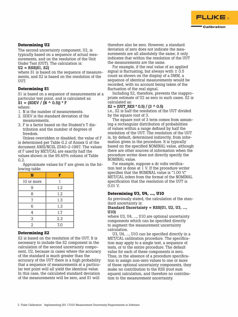
Determining S1S1 is based on a sequence of measurements at a particular test point, and is calculated as:S1 = (SDEV / (N ^ 0.5)) * Fwhere:1. N is the number of measurements.2. SDEV is the standard deviation of the
measurements.3. F is a factor based on the Student’s T dis-
tribution and the number of degrees of freedom.Unless overridden or disabled, the value of F
is determined per Table G.2 of Annex G of the document ANSI/NCSL Z540-2-1997. The values of F used by MET/CAL are exactly half the values shown in the 95.45% column of Table G.2.
Approximate values for F are given in the fol-lowing table:
N F10 or more 1
9 1.28 1.27 1.36 1.34 1.73 2.32 7.0
Determining S2S2 is based on the resolution of the UUT. It is necessary to include the S2 component in the calculation of the second uncertainty compo-nent, U2, because in cases where the accuracy of the standard is much greater than the accuracy of the UUT there is a high probability that a sequence of measurements at a particu-lar test point will all yield the identical value. In this case, the calculated standard deviation of the measurements will be zero, and S1 will
therefore also be zero. However, a standard deviation of zero does not indicate the mea-surements are all absolutely the same; it only indicates that within the resolution of the UUT the measurements are the same.
For example, if the real value of an applied signal is fluctuating, but always with ± 0.5 count as shown on the display of a DMM, a sequence of identical measurements would be recorded, with no account being taken of the fluctuation of the real signal.
Including S2, therefore, prevents the inappro-priate estimate of U2 as zero in such cases. S2 is calculated as:S2 = (UUT_RES * 0.5) / (3 ^ 0.5)i.e., S2 is half the resolution of the UUT divided by the square root of 3.
The square root of 3 term comes from assum-ing a rectangular distribution of probabilities of values within a range defined by half the resolution of the UUT. The resolution of the UUT is, by default, determined indirectly, from infor-mation given in the procedure. It is typically based on the specified NOMINAL value, although there are other sources of information when the procedure writer does not directly specify the NOMINAL value.
For example, suppose a dc volts verifica-tion test is done at 1 V. If the procedure writer specifies that the NOMINAL value is “1.00 V,” MET/CAL infers from the format of the NOMINAL specification that the resolution of the UUT is 0.01 V.
Determining U3, U4, ..., U10As previously stated, the calculation of the stan-dard uncertainty is:Standard Uncertainty = RSS(U1, U2, U3, ..., U10)where U3, U4, ..., U10 are optional uncertainty components which can be specified directly to augment the measurement uncertainty calculation.
U3, U4, ..., U10 can be specified directly in a MET/CAL calibration procedure. The specifica-tion may apply to a single test, a sequence of tests, or to the entire procedure. The default value for each of these components is zero. Thus, in the absence of a procedure specifica-tion to assign non-zero values to one or more of these optional uncertainty components, they make no contribution to the RSS (root sum square) calculation, and therefore no contribu-tion to the measurement uncertainty.

4 Fluke Calibration Implementing ISO 17025 Measurement Uncertainty Requirements in Software
Recall also that the Expanded Uncertainty is calculated as:Expanded Uncertainty = (Standard Uncertainty) * Kwhere K is the coverage factor.
Thus, a specification of U3, U4, ..., and/or U10 affects both the Standard Uncertainty and the Expanded Uncertainty.
It is up to the metrologist or procedure writer to decide when it is appropriate to assign values to the optional uncertainty components U1, U2, ..., U10. In general, these optional uncertainty components are intended for Type B uncertain-ties. These uncertainties are not directly based on the sequence of measured values, the accu-racy of the main calibration standard, or the resolution of the UUT, because those uncertainty components are incorporated in U1 and U2, which are, typically, calculated automatically by MET/CAL. As stated in ANSI/NCSL Z540-2-1997, information used to determine Type B uncer-tainties includes:• previous measurement data.• knowledge of relevant behavior and proper-
ties of materials and instruments.• manufacturer’s specifications.• calibration certificates.• uncertainties assigned to reference data
taken from handbooks.In practice, sources of additional, optional
uncertainty components may include:• test leads.• terminators.• attenuators.• power splitters.• thermocouples.• other signal conditioners.• environmental factors (temperature, humidity).
In some cases, it may be appropriate to leave all optional uncertainty components unassigned (i.e., set to zero). For example, if you are using a Fluke Calibration 5720A Multifunction Calibra-tor to calibrate a Fluke 10 digital multimeter, the resolution of the UUT may well dominate the measurement uncertainty calculation, and any uncertainty contribution from, say, test leads, will probably be negligible. On the other hand, if you are using, for example, an HP 3458A to measure a precision resistor, uncertainty due to test leads and temperature fluctuations in the calibration lab may be important.
Parameter controlThe measurement uncertainty calculation performed by MET/CAL is described in detail above. Most parameters used in the measure-ment uncertainty calculation can be overridden at the procedure level. When a parameter is specified at the procedure level, the specifica-tion remains in effect for the duration of the procedure, unless subsequently modified or reset to the default.
In some cases, parameter values can also be set at the workstation level (in a MET/CAL initialization file), or at the site level (in a data-base table). When a measurement uncertainty parameter is overridden in a procedure, the parameter value can be obtained in a number of ways:• A literal value can be specified directly• The value can be calculated using the
“MATH” function of the MET/CAL procedure language
• The operator can be prompted to enter the value, or to enter information used to calcu-late the value
• The value can be determined by a separate, user-written program, invoked automatically by MET/CALThis section provides additional information
about the measurement uncertainty parameters.
Parameter summaryThe following measurement uncertainty param-eters can be directly specified at the procedure level:• Number of Measurements• Confidence• Coverage Factor• Expanded Uncertainty• F (normally based on Student’s T)• Flag to enable or disable use of Student’s T to
determine F• “Measure Only” Flag• S1 = (SDEV / (N ^ 0.5)) * F• S2 = ((UUT Resolution) * 0.5) / (3 ^ 0.5)• Standard Uncertainty• System Accuracy• U1 = Normalized System Accuracy• U2 = RSS(S1, S2)• U3 to U10 (optional uncertainty components)• UUT Resolution
5 Fluke Calibration Implementing ISO 17025 Measurement Uncertainty Requirements in Software
Specifying the number of measurementsThe number of measurements, N, may be speci-fied, in order of increasing precedence, at the site level, the workstation level, or the proce-dure level. A procedure level specification may apply to one test, a sequence of tests, or an entire procedure.
The specified value of N indicates how many times each test step is repeated. The process of repeating a particular test step is necessary to accumulate a sequence of measurements on which to base the standard deviation calcula-tion. Legal values for N range from 0 to 1000. Setting N to zero disables the measurement uncertainty calculation. Although it is legal to set N to 1, notice that this means that the stan-dard deviation is, in effect, zero. This, in turn, means that the second uncertainty component, U2, becomes just S2, so the entire uncertainty component is then based only on the UUT resolution.
In general, it is therefore not advisable to set the number of measurements to 1. However, there may be some cases where it is acceptable to do so. One such case involves the pre-calcu-lation of S1 or U2, which may then be directly specified at the procedure level.
A second case where setting N to 1 may be acceptable is when the accuracy of the standard is sufficiently greater than the resolution of the UUT, so that any practical sequence of mea-surements is very likely to result in a standard deviation of zero (i.e., where all measurements are the same).
The procedure writer or metrologist should consider carefully the trade-offs involved in set-ting the number of measurements. Large values of N increase confidence in the standard devia-tion calculation, but also slow down execution of the procedure.
In a closed-loop procedure (where both the standard and the UUT are remotely controlled), the normal measurement plus settling time is multiplied by N. In a manual procedure, the operator will be prompted N times to enter the measured value. This can be both slow and tedious.
Specifying the confidenceThe Confidence is a statistical measure of the confidence associated with the specifications given for a calibration standard. The Confidence must be specified as a sigma value, not as a percentage. For example, if the specifications for a calibration standard are stated as having a 99 % confidence, the Confidence should be set to 2.58, which is the equivalent sigma value. In cases where the confidence associated with the specification of a calibration standard is unknown, you may wish to use 1.73 (that is, 3 ^ 0.5). This is a conservative choice based on the assumption of a rectangular distribution.
The Confidence is used to calculate Nor-malized System Accuracy. The Confidence para-meter is often referred to as a coverage factor. Recall that:Standard Uncertainty = RSS(U1, U2, ..., U10)where U1 is the Normalized System Accuracy, calculated as:Normalized System Accuracy=(System Accuracy) / Confidence
The System Accuracy is the accuracy of the calibration standard and is usually determined by looking up the value in a MET/CAL accuracy file. If the value specified in the accuracy file is incorrect for a particular test or procedure, or no accuracy file is available, the Confidence can be directly specified at the procedure level or in an initialization file.
MET/CAL includes approximately 50 different calibration standards. An accuracy file for each standard is included with the software. It is not uncommon to find that the manufacturer did not indicate a confidence value associated with the specifications for an instrument. In such cases, an attempt was made to contact the manufac-turer (for example, Hewlett-Packard) and use the Confidence value provided. In cases where it was not possible to obtain a Confidence value from the instrument manufacturer, a default value of 2 sigma was used. This value can be modified easily by a customer, however.
MET/CAL allows the procedure writer to create and use alternate accuracy files. In such cases, the Confidence should be specified in the accuracy file header. MET/CAL also allows the procedure writer to specify the accuracy of the standard directly, on a per-test basis, in the procedure. When this is done, it is necessary to directly specify the Confidence at the procedure level, unless it is acceptable to allow the Confi-dence to default to 2 sigma.

6 Fluke Calibration Implementing ISO 17025 Measurement Uncertainty Requirements in Software
Specifying the coverage factorThe Coverage Factor is used to calculate the Expanded Uncertainty as:Expanded Uncertainty = (Coverage Factor) * (Standard Uncertainty)
By convention, the value typically used for the Coverage Factor is 2, and MET/CAL V6.0 is shipped with the coverage factor set to 2 in the database.
The Coverage Factor may be specified, in order of increasing precedence, at the site level, the workstation level, or the procedure level. A procedure level specification may apply to one test, a sequence of tests, or an entire procedure. In V6.0, the Coverage Factor is one of three quantities which may be written to the results. There is no provision in V6.0 for automatically determining the coverage factor as a function of the number of degrees of freedom.
Specifying the expanded uncertaintyIf measurement uncertainty is enabled, MET/CAL normally calculates the Expanded Uncertainty as:Expanded Uncertainty = (Standard Uncertainty) * Kwhere K is the coverage factor.
However, it is possible to directly specify the Expanded Uncertainty at the procedure level. Such a specification overrides the built-in cal-culation of expanded uncertainty.
Setting the Expanded Uncertainty directly is appropriate when MET/CAL’s built-in mea-surement uncertainty calculation does not yield correct results for a particular test, and where the procedure writer has determined the uncertainty externally. Directly specifying the Expanded Uncertainty in this way removes any dependency on the measured values, number of measurements, UUT resolution, confidence value, and Student’s T distribution, for the affected tests. The dependency is removed only for the Expanded Uncertainty, however, not for the Standard Uncertainty, which will still be calculated in the normal way, unless its calcula-tion is also overridden.
In cases where the procedure writer has calculated the measurement uncertainty externally, it will usually make more sense to override the Standard Uncertainty, and, possi-bly, the Coverage Factor, and allow MET/CAL to continue to calculate the Expanded Uncertainty as the product of the two.
Specifying the F factorF is a factor based on the Student’s T distribu-tion and the number of degrees of freedom. Recall that the basic measurement uncertainty calculation is:Standard Uncertainty = RSS(U1, U2, U3, ..., U10)whereU2 = RSS(S1, S2)and whereS1 = (SDEV / (N ^ 0.5)) * F
SDEV is the standard deviation of the mea-surements, N is the number of measurements, and S2 is based on the resolution of the UUT. As mentioned previously, unless overridden or disabled the value of F is determined per Table G.2 of Annex G of the document ANSI/NCSL Z540-2-1997.Note that MET/CAL uses the simplifying assumption that the number of degrees of freedom is one less than the number of mea-surements. If this assumption is not acceptable, it may be possible for the metrologist or procedure writer to calculate F directly and override MET/CAL’s built-in determination of F.
The value of F can be directly specified in the initialization file or at the procedure level. Such a specification overrides the built-in calculation of F. An initialization file specification, unless overridden at the procedure level, applies to all tests in all procedures run on the workstation.
Disabling FSome metrologists believe that the calculation of S1 should be simply:S1 = (SDEV / (N ^ 0.5))
To support this mode, a special flag param-eter is provided to force F, in effect, to be 1.0 in all cases. To disable the use of F in the calcula-tion of S1, set the special flag (called “USE_ST”) to “no.” This can be at the database, worksta-tion, or procedure level.
By default (as distributed) MET/CAL V6.0 disables the use of F. In other words, the factor F is set to 1 and it is presumed that the Coverage Factory—typically set to 2 and used to deter-mine the Expanded Uncertainty based on the Standard Uncertainty—is sufficient to incorpo-rate the confidence in the standard deviation of the measured values as a function of the number of measurements. When the number of measurements is 10 or more, F is close to 1 in any case, and so this presumption would appear to be justified.
7 Fluke Calibration Implementing ISO 17025 Measurement Uncertainty Requirements in Software
For smaller values of N, on the other hand, the Student’s T-based F value can be significant (for example, F is 6.985 when N is 2), and the decision as to whether it’s appropriate to set F to 1 unconditionally has to be based on the judge-ment of the metrologist. Based on comments from various European and American sources, it was determined that the best approach for MET/CAL is to provide the option and allow each site to decide how to implement this aspect of the uncertainty calculation.
Specifying the “Measure Only” flag“Measure Only” is a flag parameter which can be set to “Yes” or “No.” If it is “Yes,” MET/CAL meter drivers do not re-set up the meter on the second and subsequent measurements of a sequence of measurements. This can speed up execution of certain meter-based procedures when the number of measurements is greater than 1.
It is up to the metrologist and procedure writer to determine whether the increased speed compromises the measurement uncertainty calculation. Re-setting up the meter prior to each measurement will, if nothing else, slow down the procedure and may slightly increase the chance of seeing significant deviations from one measurement to the next.
The Measure Only flag may be specified in the initialization file or at the procedure level. By default, “Measure Only” is set to “no,” i.e., in a sequence of measurements where the calibra-tion standard is a meter, the meter will be fully reprogrammed prior to each measurement.
Specifying the S1 parameterRecall that the basic measurement uncertainty calculation is: Standard Uncertainty = RSS(U1, U2, ..., U10)where U2 is calculated as:U2 = RSS(S1, S2)and where S1 is normally calculated as:S1 = (SDEV / (N ^ 0.5)) * F
In other words, S1 is normally based on the standard deviation of a series of measurements, for some number of measurements greater than 1. However, it is possible to override the normal calculation of S1 at the procedure level
and directly assign its value. If the calculation of S1 is overridden for one or more tests, this removes any dependency on the number of measurements in the measurement uncertainty calculation for those tests. The procedure writer should, in that case, set the number of measure-ments to 1, unless it is specifically expected that the measurement result be reported as an average of values rather than as a single measurement.
Specifying the S2 parameterRecall that the basic measurement uncertainty calculation is:Standard Uncertainty = RSS(U1, U2, ..., U10)where U2 is calculated as:U2 = RSS(S1, S2)and where S2 is normally calculated as:S2 = ((UUT Resolution) * 0.5) / (3 ^ 0.5)
In other words, S2 is normally a function of the UUT resolution. However, it is possible to override the normal calculation of S2 at the procedure level and directly assign its value. If the calcula-tion of S2 is overridden for one or more tests, this removes any dependency on the UUT resolution in the measurement uncertainty calculation for those tests.
Specifying the standard uncertaintyNormally,Standard Uncertainty = RSS(U1, U2, ..., U10)
However, it is possible to override the normal calculation of Standard Uncertainty at the procedure level and directly assign its value. Overriding the normal calculation of Stan-dard Uncertainty is appropriate only where the procedure writer has externally determined the measurement uncertainty associated with a test. Directly specifying the value of the Standard Uncertainty in this way removes any dependency on the measured values, number of measure-ments, UUT resolution, confidence value, and Student’s T distribution, for those tests.
The only subsequent calculation performed using the specified Standard Uncertainty is:Expanded Uncertainty = (Standard Uncertainty) * Kwhere K is the coverage factor.
8 Fluke Calibration Implementing ISO 17025 Measurement Uncertainty Requirements in Software
Specifying the system accuracyThe basic measurement uncertainty calculation is:Standard Uncertainty = RSS(U1, U2, ..., U10)where U1 is the Normalized System Accuracy, calculated as:U1 = (System Accuracy) / Confidence
System Accuracy is represented in absolute units (e.g., 0.1 V), and Confidence is expressed as a sigma value (e.g., 2.58 sigma).
Normally the System Accuracy is looked up in a MET/CAL accuracy file. The accuracy file used is typically selected automatically, based on the instrument (the calibration standard), and the calibration interval specified for the particular configured standard in use. The procedure writer may override the normal accuracy file selec-tion and directly specify the use of an alternate accuracy file.
It is also possible, at the procedure level, to directly specify the System Accuracy for the mea-surement uncertainty calculation. It is important to understand that direct specification of the System Accuracy in this way does not affect the TUR calculation, which will continue to be based on accuracy file lookup.
An alternative approach, which can be used in closed-loop procedures, is to use the “ACC” procedure statement to directly specify the system accuracy in a way that affects both the TUR and the measurement uncertainty.
Direct specification of System Accuracy is par-ticularly useful in cases where MET/CAL’s built-in accuracy file lookup is not adequate to determine the accuracy of a standard. For example, counter accuracies typically cannot be represented as:(percentage of NOMINAL)+floorand therefore the standard accuracy file lookup does not work for these devices.
The procedure writer may wish to directly specify the System Accuracy in these cases in order to allow the measurement uncertainty cal-culation to proceed.
Specifying the U1 parameterThe basic measurement uncertainty calculation is:Standard Uncertainty = RSS(U1, U2, ..., U10)where U1 is the Normalized System Accuracy, calculated as:U1 = (System Accuracy) / Confidence
However, it is possible to override the normal determination of U1 and directly assign its value. When U1 is directly specified the calculated measurement uncertainty no longer depends on the System Accuracy or Confidence, both of which are usually based on accuracy file lookup.
Specifying the U2 parameterThe basic measurement uncertainty calculation is:Standard Uncertainty = RSS(U1, U2, ..., U10)where U2 is calculated as:U2 = RSS(S1, S2)and where S1 is normally calculated as:S1 = (SDEV / (N ^ 0.5)) * Fand where S2 is normally calculated as:S2 = ((UUT Resolution) * 0.5) / (3 ^ 0.5)
However, it is possible to override the normal determination of U2 and directly assign its value. When U2 is directly specified, the calculated measurement uncertainty no longer depends on the measured values, the number of measure-ments, the Student’s T distribution, or the UUT Resolution.
Directly specifying U2 is appropriate in cases where the procedure writer or metrologist has determined that MET/CAL should calculate mea-surement uncertainty using the usual RSS (root sum square) calculation, including the normal-ized system accuracy component, and, possibly, optional uncertainty components U3, U4, ..., U10, but where the usual (empirical) determination of uncertainty component U2 based on the stan-dard deviation of the measured values and the resolution of the UUT (Unit Under Test) is incor-rect or inappropriate.
9 Fluke Calibration Implementing ISO 17025 Measurement Uncertainty Requirements in Software
Specifying optional uncertainty compo-nents (U3, U4, ..., U10)The optional uncertainty components U3, U4, ..., U10 default to zero if not directly specified at the procedure level. Zero or more optional components may be specified on a per-test basis. Values persist within a procedure until changed or reset. Refer to the section “Determining U3, U4, ..., U10” above for addition information.
Specifying the UUT resolutionThe basic measurement uncertainty calculation is:Standard Uncertainty = RSS(U1, U2, ..., U10)where U2 is calculated as:U2 = RSS(S1, S2)and where S1 is normally calculated as:S1 = (SDEV / (N ^ 0.5)) * Fand where S2 is normally calculated as:S2 = ((UUT Resolution) * 0.5) / (3 ^ 0.5)
Unless overridden, MET/CAL attempts to infer the UUT’s resolution based on information in the procedure. (Actually, MET/CAL has always done this, but prior to V6.0 the inferred infor-mation was used only to control the formatting of certain result quantities.) In V6.0, the UUT Resolution is needed to determine the measure-ment uncertainty.
If the automatically determined UUT resolu-tion is incorrect or inadequate, the procedure writer may directly specify the UUT resolution. The UUT Resolution is expressed in absolute units (Volts, Amps, etc.)
The details of how MET/CAL attempts to infer the UUT Resolution from procedural informa-tion are not given here. However, the procedure writer must be cognizant of the fact that MET/CAL cannot always reliably infer the UUT resolution, especially in cases where the Nominal value of the test, or the test tolerance, are not statically known but, rather, are prompted for or calculated at run time. In such cases, the UUT Resolution should be directly specified at the procedure level. The specification may apply to a single test, a group of related tests, or to the entire procedure.
Flow controlIn the MET/CAL procedure language, a test is a sequence of one or more procedure statements, which determine a single result at a particular test point. In “closed-loop” procedures, where the Unit Under Test (UUT) can be controlled remotely, full automation requires that the test typically will consist of several discrete parts:(a) Set up the calibration standard(b) Set up the UUT(c) Read the measured value(d) Compare the measured value to the expected
value and generate a test resultDepending on the particular test and the
particular instruments involved, it may or may not be necessary to prompt the operator to make certain connections as part of the test. The mea-surement uncertainty calculation requires that some or all of the parts of such a test be repeated automatically, once for each measurement in the measurement sequence.
The question arises, then, as to how many of the procedure statements in the test step should be repeated on the second and subsequent measurements? In some cases, such as when the operator is prompted to make a connection, it is clear that requiring that the connection be broken and remade for each measurement in the sequence would be annoying to the operator, and probably pointless. In other cases, such as the decision whether to re-set up the calibration standard for each measurement, it’s a judgement call. There may be some merit, from the mea-surement uncertainty point of view, in repeating as much as possible of the entire measurement step. On the other hand, doing so slows down procedure execution.
To provide full flexibility, a new procedure statement, “TARGET,” has been added to the MET/CAL procedure language. The procedure writer may insert a TARGET statement at any desired point in a test. This causes execution of the second and subsequent measurements to commence at the first procedure statement after the TARGET statement.
10 Fluke Calibration Implementing ISO 17025 Measurement Uncertainty Requirements in Software
For compatibility with existing compiled procedures, however, MET/CAL also applies certain built-in rules to determine how much of a multi-statement test to re-execute on the second and subsequent measurements when there’s no TARGET statement in the test. Some statement types, like operator prompts to make connections are, by default, not repeated. Other statement types, like low-level IEEE-488 or serial com-mands to set up and query the UUT are, by default, repeated each time.
ConclusionThe implementation of the measurement uncer-tainty calculation in MET/CAL V6.0 had two main goals:1. To define built-in calculations which correctly
calculate the measurement uncertainty in most cases. The measurement uncertainty calcula-tion can be done for many procedures without any required procedure modification.
2. To provide a flexible implementation which allows the procedure writer to override some or all of the built-in calculation, and to include optional uncertainty components as needed.Our plan for subsequent versions of MET/CAL
is to listen carefully to customer feedback on the measurement uncertainty implementation and add capability as needed when cases arise where the measurement uncertainty cannot be calculated in a satisfactory manner, or where it can be done manually but further automation is feasible.
References(1) DIS 17025 “General Requirements for the Competence of
Testing and Calibration Laboratories.”(2) ANSI/NCSL Z540-2-1997 “U.S. Guide to the Expression of
Uncertainty in Measurement.”(3) EAL-R2 “Expression of the Uncertainty of Measurement in
Calibration.” Note: The most recent version of this document is designated
“EA-4/02.”(4) EAL-R2-S1 “Supplement 1 to EAL-R2 Expression of the
Uncertainty of Measurement in Calibration.”(5) “Guidelines on the Evaluation and Expression of the Mea-
surement Uncertainty,” Singapore Institute of Standards and Industrial Research, First Published July 1995.
(6) Calibration: Philosophy in Practice, 2nd Edition, Fluke Corpo-ration, ISBN 0-9638650-0-5.
(7) Mr. Ray Kletke, Fluke Standards Lab.(8) Mr. David Deaver, Fluke Standards Lab.(9) “Software and Hardware Considerations for Automated Cali-
bration Systems,” Peter Dack, Wavetek Calibration Division.
Fluke Calibration PO Box 9090, Everett, WA 98206 U.S.A.
Fluke Europe B.V. PO Box 1186, 5602 BD Eindhoven, The Netherlands
For more information call: In the U.S.A. (877) 355-3225 or Fax (425) 446-5116 In Europe/M-East/Africa +31 (0) 40 2675 200 or Fax +31 (0) 40 2675 222 In Canada (800)-36-FLUKE or Fax (905) 890-6866 From other countries +1 (425) 446-5500 or Fax +1 (425) 446-5116 Web access: http://www.flukecal.com
©1999-2012 Fluke Calibration. Specifications subject to change without notice. Printed in U.S.A. 3/2012 1282496C A-EN-N Pub_ID: 11xxx-eng
Modification of this document is not permitted without written permission from Fluke Calibration.
Fluke Calibration. Precision, performance, confidence.™