implementation of user interface for microprocessor …
TRANSCRIPT
D.C. Wyld, et al. (Eds): CCSEA 2011, CS & IT 02, pp. 375–387, 2011.
© CS & IT-CSCP 2011 DOI: 10.5121/csit.2011.1233
IMPLEMENTATION OF USER INTERFACE
FOR MICROPROCESSOR TRAINER
TinMarKyi
ComputerUniversity(Mandalay)
ABSTRACT
This paper aims to design and construct the microcontroller - based userinterface system and to
study input, computation and output for microprocessor trainer.The other two activities beyond
computation :input and output or I/O.This paper also aims to do high quality research in the
area of filesystems, as well as develop a good implementation on atleast one computersystem. A
computersystem's I/O performance must be commensurate (equal) with its CPU performance if
the I/O system is not to limit the system's total throughput.When hundreds to thousands of such
highperformance micro-processors are closely connected inscalablearray architecture, the
enormous CPU performance of the multi-computer requires an I/O system with correspondingly
high performance.A wellbalanced computer requires I/O performance commensurate with its
CPU performance. High performance computers, access large numbers of disks in parallel to
achieve the very appreciable I/O performance.
KEYWORDS
I/Ounit, MicroprocessorTrainer, PIC16F877Amicrocontrolle, 7segments, 74ALS573BS,
74LS244, twoULN2004A.
1. INTRODUCTION
A microcontroller is a complete computer system, including a CPU, memory, a clock oscillator,
and I/O on a single integrated circuit chip. The parts of any computer are:
A central processor unit (CPU)
Memory for instructions and data
Inputs to get information into the computer system
Outputs to get information out of the computer system
A program to make the computer do something useful I/O is one of the basic principles in
computer science– data is given to a processing unit, which processes the data end gives out the
results. Usually memory chips are used to buffer that data, so in most cases the data is copied
376 Computer Science & Information Technology (CS & IT)
from the sensors into a buffer, than processed and then copied back into another buffer.
Furthermore, data is exchanged between the components of an embedded system via buses.
Inputs can only process digital input signals at the same voltage levels as the main logic power
source. The 0volt ground level is called VSS and the positive power source (VDD) is typically 5
Vdc (direct current). A level of approximately 0 volts indicates a logic 0 signal and a voltage
approximately equal to the positive power source indicates a logic 1 signal. Output devices are
used to communicate information or actions from the trainer system to the outside world. In
trainer system outputs are logic level digital signals that are used to drive display LED (Light
Emitting diodes) [15].
Most Microcontrollers are general purpose Microprocessors which have additional parts that
allow them to control external devices. We often use the terms Microcontroller and
Microprocessor interchangeably [3].
The key difference between a microprocessor and a microcontroller is that a microprocessor
contains only a central processing unit (CPU) while a microcontroller has memory and I/O on the
chip in addition to a CPU. Microcontrollers are generally used for dedicated tasks.
Microcomputer is a general term that applies to complete computer systems implemented with
either a microprocessor or microcontroller [8].
2. RELATEDWORK
PICs are popular with developers due to their low cost, wide availability, large user base,
extensive collection of application notes, availability of low cost or free development tools, and
serial programming(and reprogramming with flash memory)capability[2].Developing a PIC
microcontroller based project simply takes no more than five or six steps.
Type the program into a PC
Assemble (or compile) the program
Optionally simulate the program on a PC
Load the program into PIC’s program memory Design and construct the hardware
Test the project [2].
The purpose of this trainer is to provide students with experience in the following techniques:
writing of assembly language programs
assembling, downloading and running of programs
programming to output characters to 7segment displays
programming to read keypad characters
generation of waveforms for display on an oscilloscope
uses of interrupt facilities
implementation of timing routines using the on chip hardware timer
The machine is a freestanding piece of training equipment, incorporating its own power supply,
Computer Science & Information Technology (CS & IT) 377
input keypad and output digital display [20, 21].The design of computers, covers the overall
design, or architecture and internal details or organization[22].The communication between a
computer and its human users, a means of translating information between human and binary
formats is necessary. The input output equipment can perform this task[23].
3. CONTRIBUTION
The main contribution of this thesis is to design and construct the general purpose of
instrumentation and user interface module. The executed programs of this thesis are the technical
features, the hardware design and the control software of user interface(I/O)system.
A useful step forward from the simple switch is given by the keypad, as seen in the photocopier
interface and the Derbot hand controllers. The keypad allows numeric or alphanumeric
information to be entered. It is widely used in photocopiers, burglar alarms, and central heating
controllers and so on.
A keypad is based on switches, yet it would be extremely resource intensive if each of these
switches were allocated to a port bit. Instead, to make good use of resource, each switch is
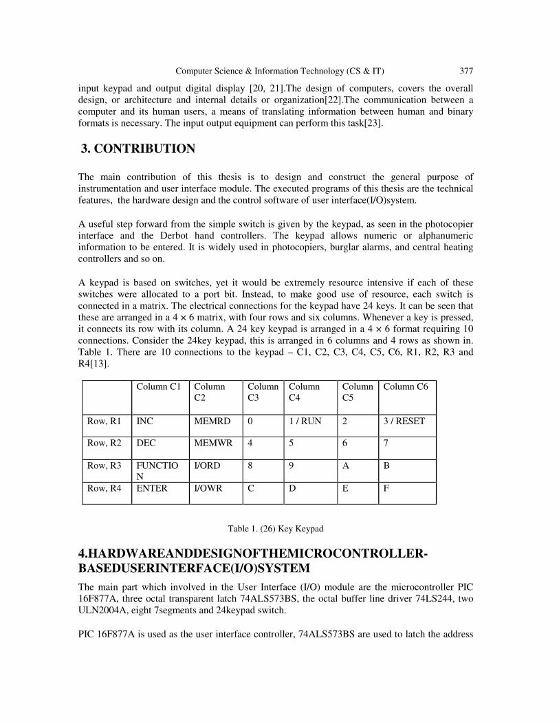
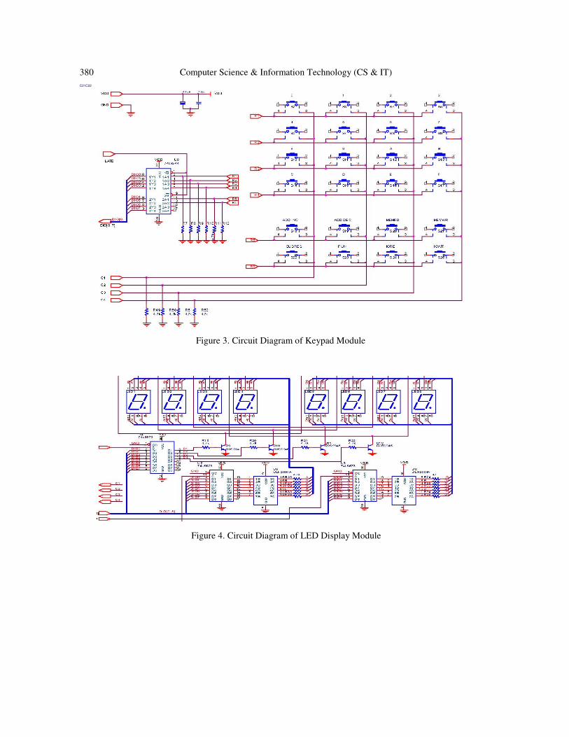
connected in a matrix. The electrical connections for the keypad have 24 keys. It can be seen that
these are arranged in a 4 × 6 matrix, with four rows and six columns. Whenever a key is pressed,
it connects its row with its column. A 24 key keypad is arranged in a 4 × 6 format requiring 10
connections. Consider the 24key keypad, this is arranged in 6 columns and 4 rows as shown in.
Table 1. There are 10 connections to the keypad – C1, C2, C3, C4, C5, C6, R1, R2, R3 and
R4[13].
Column C1 Column
C2
Column
C3
Column
C4
Column
C5
Column C6
Row, R1 INC MEMRD 0 1 / RUN 2 3 / RESET
Row, R2 DEC MEMWR 4 5 6 7
Row, R3 FUNCTIO
N
I/ORD 8 9 A B
Row, R4 ENTER I/OWR C D E F
Table 1. (26) Key Keypad
4.HARDWAREANDDESIGNOFTHEMICROCONTROLLER-
BASEDUSERINTERFACE(I/O)SYSTEM
The main part which involved in the User Interface (I/O) module are the microcontroller PIC
16F877A, three octal transparent latch 74ALS573BS, the octal buffer line driver 74LS244, two
ULN2004A, eight 7segments and 24keypad switch.
PIC 16F877A is used as the user interface controller, 74ALS573BS are used to latch the address
378 Computer Science & Information Technology (CS & IT)
output from either the main CPU or from the DMA controller, 74LS 244 is used to drive the
control bus signals.
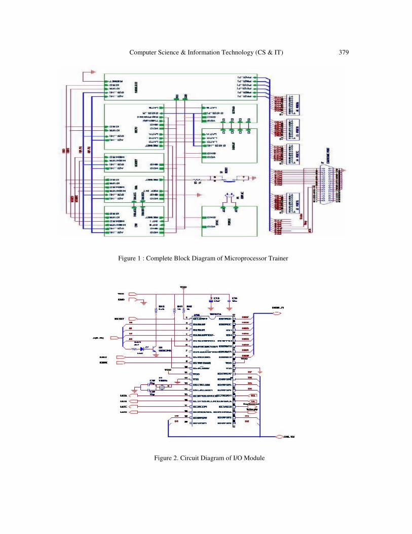
The hardware configuration of the experimental setup and the software organization will be
summarized. In the Microprocessor Trainer system, the program debugger, a kind of DMA
(Direct Memory Access) controller, is contained in one of the hardware module. There are totally
six modules (Processor module, Memory module, User Interface module, DMA (Direct Memory
Access) module, PIO (Parallel Input/Output) module and Power Supply module) in the Trainer
system and all modules are provided as separate chip, linked together via bus connections on a
printed circuit board and supplied 5V DC power. The block diagram of the system is shown in
figure (5.1). The Microprocessor Trainer used the 16bit wide address bus (A [0…15]) and data
bus (D [0…15]) and four control signals such as MEMWR, MEMRD, IOWR and IORD. The
system buses are used by the main processor and the DMA controller alternatively.
The main part which involved in the User Interface (I/O) module are the microcontroller PIC
16F877A, three octal transparent latch 74ALS573BS, the octal buffer line driver 74LS244, two
ULN2004A, eight7segmentsand24keypadswitch.
PIC 16F877A is used as the user interface controller, 74ALS573BS are used to latch the address
output from either the main CPU or from the DMA controller, 74LS 244 is used to drive the
control bus signals.
All parts of the module are controlled by ALE (address Latch Enable) pin from the main CPU. By
passing the DMK ACK pin is going to low level, the main CPU gives the bus service to the DMA
goes low. The PIC16F877A is connected to LEDs in a similar fashion to the user interface system
PORT B is used as the LSBand is connected to LEDs. PORTD is used as the MSBand is
connected to LEDs.
The interrupt pin from the user interface system is tied to the capture input pin of the
PIC16F877A (RC1/CCP2) and is pulled high using a 1k resistor (R98). The I/O address pins
areconnectedtoswitchS2.This is done for testing purposes to allow change of addresses using the
switch. The sepins can be tied permanently high or low. The I2
Cpins (SDA and SCL)from all
devices (U1 and U2) are connected together to form the IC bus. Both SDA and SCL are pulled
high using 4.7 k resistors.
Computer Science & Information Technology (CS & IT) 379
Figure 1 : Complete Block Diagram of Microprocessor Trainer
Figure 2. Circuit Diagram of I/O Module
380 Computer Science & Information Technology (CS & IT)
C21C22
Figure 3. Circuit Diagram of Keypad Module
Figure 4. Circuit Diagram of LED Display Module

Computer Science & Information Technology (CS & IT) 381
Figure 5. Circuit diagram of I/O port
5. Controlling with PIC16F877 Assembly Software
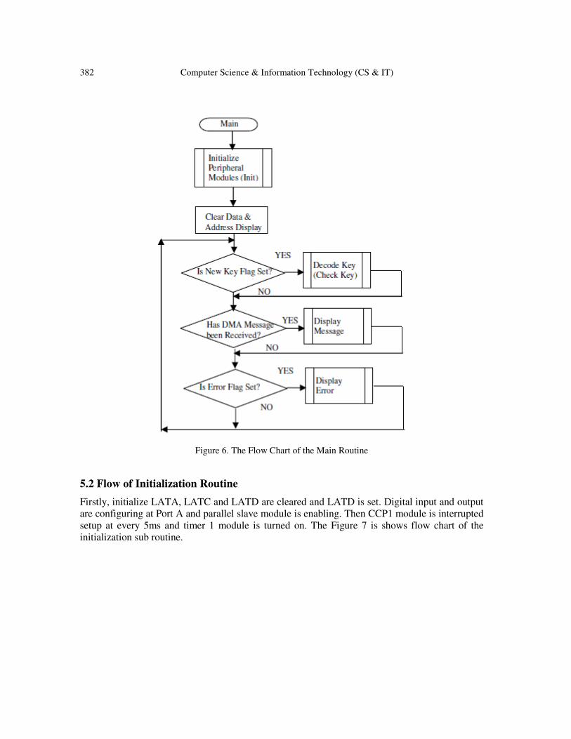
5.1 Flow of the Main Routine
Before entering the Main Loop the software initializes peripheral modules. In the main loop, the
program checks for three flags. New key Flag, DMA message Flag and Error Flag. If newkey
flag is found; it performs decoding operation. If DMA message is set it will displays message
code ON the LED display and if error flag is set it will display error code.
382 Computer Science & Information Technology (CS & IT)
Figure 6. The Flow Chart of the Main Routine
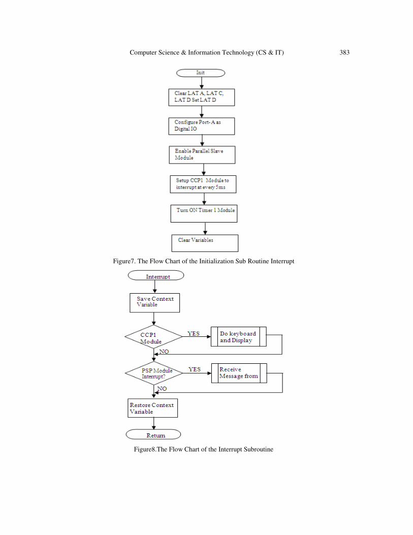
5.2 Flow of Initialization Routine
Firstly, initialize LATA, LATC and LATD are cleared and LATD is set. Digital input and output
are configuring at Port A and parallel slave module is enabling. Then CCP1 module is interrupted
setup at every 5ms and timer 1 module is turned on. The Figure 7 is shows flow chart of the
initialization sub routine.
Computer Science & Information Technology (CS & IT) 383
Figure7. The Flow Chart of the Initialization Sub Routine Interrupt
Figure8.The Flow Chart of the Interrupt Subroutine
384 Computer Science & Information Technology (CS & IT)
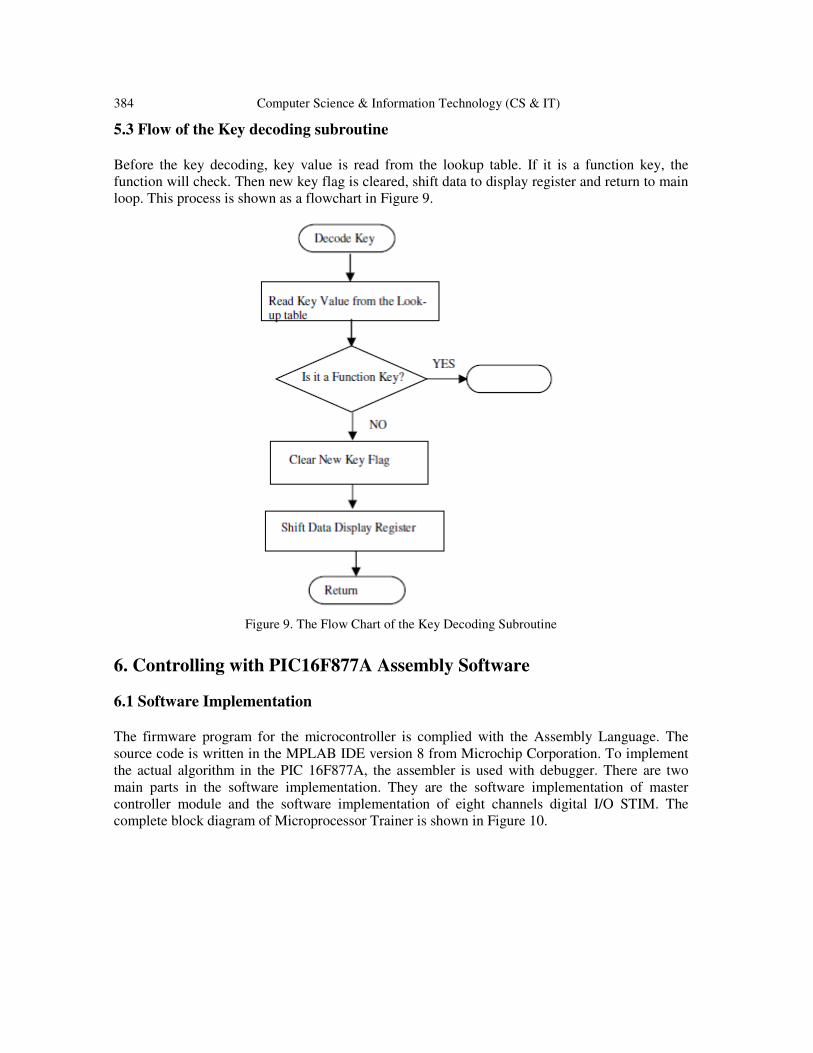
5.3 Flow of the Key decoding subroutine
Before the key decoding, key value is read from the lookup table. If it is a function key, the
function will check. Then new key flag is cleared, shift data to display register and return to main
loop. This process is shown as a flowchart in Figure 9.
Figure 9. The Flow Chart of the Key Decoding Subroutine
6. Controlling with PIC16F877A Assembly Software
6.1 Software Implementation
The firmware program for the microcontroller is complied with the Assembly Language. The
source code is written in the MPLAB IDE version 8 from Microchip Corporation. To implement
the actual algorithm in the PIC 16F877A, the assembler is used with debugger. There are two
main parts in the software implementation. They are the software implementation of master
controller module and the software implementation of eight channels digital I/O STIM. The
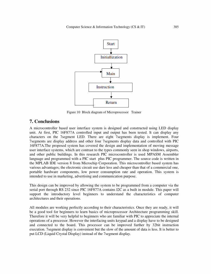
complete block diagram of Microprocessor Trainer is shown in Figure 10.
Computer Science & Information Technology (CS & IT) 385
Figure 10 Block diagram of Microprocessor Trainer
7. Conclusions
A microcontroller based user interface system is designed and constructed using LED display
unit. At first, PIC 16F877A controlled input and output has been tested. It can display any
characters on the 7segment LED. There are eight 7segments display is implement. Four
7segments are display address and other four 7segments display data and controlled with PIC
16F877A.The proposed system has covered the design and implementation of moving message
user interface systems, which are contrast to the types commonly seen in shop windows, airports,
and other public buildings. In this research PIC microcontroller is used MPASM Assembler
language and programmed with a PIC start plus PIC programmer. The source code is written in
the MPLAB IDE version 8 from Microchip Corporation. This microcontroller based system has
various advantages; the electronic circuit use dare less and cheaper than that of a commercial one,
portable hardware components, low power consumption rate and operation. This system is
intended to use in marketing, advertising and communication purpose.
This design can be improved by allowing the system to be programmed from a computer via the
serial port through RS 232 since PIC 16F877A contains I2C as a built in module. This paper will
support the introductory level beginners to understand the characteristics of computer
architectures and their operations.
All modules are working perfectly according to their characteristics. Once they are ready, it will
be a good tool for beginners to learn basics of microprocessor Architecture programming skill.
Therefore it will be very helpful to beginners who are familiar with PIC to appreciate the internal
operations of a processor. However the interfacing units keypad and a display have to be designed
and connected to the board. This processor can be improved further by 32bit instruction
execution. 7segment display is convenient but the slow of the amount of data is less. It is better to
put LCD (Liquid Crystal Display) instead of the 7segment display.

386 Computer Science & Information Technology (CS & IT)
Acknowledgements
First of all, I would like to thank to His Excellency Minister U Aye Myint, Ministry of Science
and Technology for the opening of Doctor of Philosophy Degree courses.
I am very much indebted to Dr. Ni Lar Thein, Rector of University of Computer Studies Yangon,
for her enthusiastic support and permission to carryout this thesis.
I would like to profoundly grateful to U Kyaw Swa Soe, Prorector, University of Computer
Studies, Yangon for his invaluable advice, guidance and encouragement on this thesis.
Thanks are also extended to Professor Daw New Ni, Head of Computer Hardware Technology
Department, University of Computer Studies, Yangon. I would like to express my gratitude and
deep appreciation to Dr. Mie Mie Thet Thwin, Prorector, University of Computer Studies,
Mandalay for her valuable supporting to complete the whole thesis.
Her Sincere thanks go to her Supervisor, Professor Dr. Win Aye, Material Science and Material
Engineering Research Centre for her invaluable guidance, advance, and encouragement for this
thesis.
I am very thankful to U Win Khaing Moe, Deputy Director General, Myanmar Science and
Technological Research Department for his kind advice and guidance to complete this thesis.
I also wish to express my deepest gratitude my parents,my sisters and my brother for their
encouragement, understanding and support through out the period of this painstaking research.
References
[1] B. Williams “Designer’s Handbook of Int egrated Circuits” McGrawHill book comp any
[2] Ken Arnold, “Embedded Controller Hardw are D esign”, LLH T echnology Publishing, in 2000.
[3] Andrews. Tanenbaum, “ Structured C omputer Organiz ation”, PrenticeHall of India, in 1999.
[4] David A. Patterson & John L.Hennessy, “Computer Organization and Design”, First Print ed in
India, in 2005.
[5] Julio Scanchez & Maria.P, Canton, “Microcontroller Programm ing”, Tailor and Franci Group LLC,
in 2007.
[6] “PIC Microcontroller MidRange MCU Family Reference M anual”, Microchip T echnology
Incorporated, U SA, in 1997.
[7] Randall Hyde, “The Art of Assem bly Language Programming”, in 2001.
[8] DOUGLAS V.HALL, “Microprocessors and Int erfacing”, Programming & Hardware, 2/E Int
ernational Edition, 1992.
[9] Dogan Ibrahim”, PIC BASIC Projects 30 Projects Using PIC BASIC and PIC BA SIC PRO ”, Linacre
House, Jordan Hill, Oxford OX2 8DP, UK 30 Corporate Drive, Suit e 400, B urlington, MA 01803,
USA 2006.
Computer Science & Information Technology (CS & IT) 387
[10] Julio Sanchez and Maria P. Cant on,” Microcontroller Programming T he Microchip PIC ”, Taylor &
Francis Group CRC press, 2007.
[11] “PIC microT M MidRange MCU Family Reference Manual”, Technology Microchip Incorporated,
Print ed in t he U.S.A, 2002
[12] Elsevier, “Interfacing PIC Microcontrollers Embedded Design by Interactive Simulation”, Mart in
Bates, in 2006.
[13] Tim Wilmshurst,” Designing Embedded Systems with PIC Principles and Microcontrollers
applications”, Published by Elsevier Ltd, 2007.
[14] Dogan Ibrahim, “PIC BASIC Projects 30 Projects Using PIC BASIC and PIC BA SIC PRO ” Linacre
House, Jordan Hill, Oxford OX2 8DP, UK, in 2006
[15] James M.Sibigtroth, “M68HC05 Family, Understanding Small Microcontrollers Rev. 2.0”,
[16] M.E.Sloan, “Comput er Hardw are and Organization An Introduction Second Edition”, Intel
Corporation, 1975.
[17] Barry B. Brey, “The Int el Microprocessors”, PrenticeHall, in 2000.
[18] E.A.PARR, “The Logic Designer’s Guide Book”, Printed in the Unit ed States of America, in 1984.
[19] Rafiquzzaman, M.,Microprocessor Theory and Applications, Intel and Motorola, Englewood:
Prentice Hall International Editions, 1992.
[20] Hall,V., Microprocessor and Interfacing Programming and Hardware, ComputerScience series,
NewYork: McGrawHil lInternational Edition, 1986.
[21] Collier,M., An Introduction to Microcontrollers and Picocontrollers, NUST Lecture Notes Series
No.5, NUST, Bulawayo, 1999.
[22] JohnP.Hays, Computer Architecture and Organization, ISBN 0071159975, Third Edition,1997..
[23] Furbur, S.B.VLSIRSC Architecture and Organization, NewYork: MarcelDekker, 1989
[24] Siewiorek, D.P.and R.S.Swarz. Reliable Computer Systems. 2ed.Burlington,MA:Digital
Press,1992.
Author
Dr.Tin Mar Kyi is a Lecturer in Engineering Physics Department at
Computer University of Mandalay. Dr.Tin Mar Kyi received her
Master Degree from University of Computer Studies at 2000.She have
received her Ph.D (Computer Hardware Technology)
DegreefromUniversity ofComputer Studiesat 2008.Sheis
amemberofIndustrialAssociation for Parallel Processing at Computer
University ( Mandalay).