implementation of high speed low power ieee 754 floating point addition/subtraction using xilinx...
DESCRIPTION
This paper presents an IEEE 754 floating point Addition/Subtraction design. It is designed for normalized single precision IEEE 754 floating point numbers, to give the correctly normalized sum/difference in the IEEE 754 standard representation. Our floating point design achieves high speed, low power and minimum number of slice registers, by combining these several optimization techniques together in one design.TRANSCRIPT

Page 1
Implementation of High Speed Low Power IEEE 754 Floating Point
Addition/Subtraction Using Xilinx 12.3
Reham Murrar Computer Engineer Department, Faculty of Computer and Information Technology
Jordan University of Science and Technology, Irbid-Jordan
Email: [email protected]
Noor Awad Computer Engineer Department, Faculty of Computer and Information Technology
Jordan University of Science and Technology, Irbid-Jordan
Email: [email protected]
Abstract
This paper presents an IEEE 754 floating point Addition/Subtraction design. This design is
prepared by Reham Murrar and Noor Awad, as a research project at Jordan University for Science
and Technology, under the supervision of Dr. Khaldoon Mhaidat. It is designed for normalized
single precision IEEE 754 floating point numbers, to give the correctly normalized sum/difference
in the IEEE 754 standard representation. Our floating point design achieves high speed, low power
and minimum number of slice registers, by combining these several optimization techniques
together in one design. This adder takes any two binary numbers as inputs and checks for
normalized or de-normalized numbers, positive or negative numbers, infinity and floating point
numbers. It supports additional input that controls the selected operation; add or sub. It also
supports two output flags; overflow and underflow. All of these features are designed using Xilinx
ISE Design Suit 12.3. At the end of this paper we make a quick look over another single precision
floating point addition algorithms from other papers and literature, and compare these algorithms
with our algorithm.
Key words: IEEE 754 floating point, addition, subtraction, CSA, carry ripple adder, carry select
asdder.

Page 2
1. Introduction
Addition and subtraction are the most used
operations in floating point. In this paper we
present our design for single precision floating
point addition/subtraction that supports IEEE
754 standard format. This design has a
powerful enhancement in speed, area and
power compared with other designs when
they are compared. This design is
implemented in Xilinx software, of version
12.3, using the Virtex-6 family, and introduces
single precision floating point
addition/subtraction.
For the enhancement, several optimization
techniques we take in consideration while
building this fast design:
a) For the speed and area enhancements,
there is an enhancement from the software
itself that make my design fast enough and use
minimum area. And the second enhancement
is in the hardware design, by increase the
using of carry save adders and use the idea of
carry select adder since they are very fast, and
decrease the using of carry ripple adders since
they are too slow.
b) Increase the use of shifts, and replace
some complex operations such as addition and
multiplication by using the shifts, since they
are too fast compared to the first ones.
c) Post-normalization is advanced step,
but still important step to get true results.
d) For the power reduction enhancements,
we make the enhancements of it by the
enhancement that the Xilinx offer to me.
e) Check the input numbers is the first
step, and it is important step to detect that the
two input numbers are in the allowable range
of the floating point numbers, and we can
make the addition or the subtraction over
these numbers over them or not.
This paper focuses on the implementation of
high speed floating point addition and
subtraction operations. Implementations of
different algorithms on Xilinx are investigated.
Results for single precision of the implemented
operations are analyzed and compared with
other algorithms presented in papers. The
design and its implementation will be
explained in more details in the following
section.
2. Floating Point
Addition/Subtraction Algorithm
2.1. IEEE Floating Point Standard
representation IEEE 754 has three types of format: Single,
Double and Quad. Here in this paper we focus
only on the first format and make big
enhancement in its hardware implementation
to make fast addition or subtraction of two
binary numbers with minimum power
consumption.
For the IEEE 754 Single Precision floating
point representation, a number in this
format is consists of 32 bits that are
divided into three regions as shown in
Figure 1:
Sign Bit: this bit detect if the number is
positive or negative, and locate on the most
significant bit; bit 31.

Page 3
Exponent Bits: it is 8 bits, and have a range
from -126 127, and its located from bits
23 – 30.
Fraction Bit: and these bits represent the
fraction of a number, and it occupies the
lower 23 bits of the 32 bits number.
Figure 1: IEEE 754 Floating Point Standard Representation
The standard formula for the IEEE standard
Single precision of floating point is as follow:
Before start making the addition or
subtraction, we first check the number if it is in
the range and does not have any special case
number such as NaN or Infinity or zero or de-
normalize etc. these special numbers for the
single precision representation can be
computed as shown below:
Positive Infinity: is presented when the
exponent takes the maximum number, and the
fraction is zero and the sign is positive.
Negative Infinity: is presented when the
exponent takes the maximum number, and the
fraction is zero but the sign is negative.
Positive NaN: is presented when the
exponent takes the maximum number, and the
fraction is not a zero and the sign is positive.
Negative NaN: is presented when the
exponent takes the maximum number, and the
fraction is not a zero but the sign is negative.
Positive Zero: is presented when the
exponent takes the minimum number (zero),
and the fraction is zero and the sign is positive.
Negative Zero: is presented when the
exponent takes the minimum number (zero),
and the fraction is zero but the sign is negative.
Positive Denormalized: is presented
when the exponent takes the minimum
number (zero), and the fraction is not zero and
the sign is positive.
Negative Denormalized: is presented
when the exponent takes the minimum
number (zero), and the fraction is not zero but
the sign is negative.
Otherwise, the number will be in the range of
the number that accepts any operation on it.
2.2. Bitwise Algorithm
This first phase is a functional phase that we
don’t interested in the speed nor in the power
reduction; we just interested in taking the
inputs and give the correct output, and
compare it with the actual result.
In Bitwise Full Adder, the main module that
does this task is the FA module. This module is
basically a combinational model that is
collection of logical gates, and is executed 23
times taking 1 bit execution each time, as
shown in the two following equations:
SUM = A ^ B ^ Cin
Cout = (A&B) + (A&Cin )+ (B&Cin )
Where A,B and Cin represent only one bit of the
fraction.
2.3. Plus operator Algorithm
This implementation is the second one that we
try to make some enhancement in speed, by
changing the design of bitwise to full size, by

Page 4
using a plus (+) operator for the full size as
follow:
SUM = A + B
Where A,B represent the full size of fraction;
which is 23 bits.
3. Implementation of High Speed,
Less Power Consumption
Algorithm
3.1. Carry save adder with carry
select Adder Algorithm
The last design that we build is differ at all
from the previous ones, this design is a
hierarchy of carry save adders using the idea
of carry select adder also, and in last level a
carry ripple adder is used.
This adder takes three inputs: the two binary
numbers that we want to take their sum or
difference, and a one bit control to determine
the operation as shown in Figure 2. It has six
outputs: the result, last carry, two flags:
overflow and underflow and two control fields
for the two inputs; such as NaN, Infinity,
zero…etc. the Op input bit is used to select the
operation; add or sub as shown in Table 1.
Figure 2: Floating Point Addition/Subtraction block diagram
Table 1: Operation Control Feild
op Operation
0 Addition
1 Subtraction
3.1.1. The Algorithm
First, the two binary inputs are checked using
the FPControl module as shown in Figure 3 for
being negatives (NegN), infinities (InfN), not a
numbers (NAN), de normalized numbers
(DenN), zeros (ZN) and floating point numbers
(FPN). As shown in Table 3, the input is zero if
its exponent and its fraction in zeros, whether
an input is negative if the most significand is 1,
the input is de normalized number if its
exponent is zero where its fraction not equals
to zero, the input is infinity when its exponent
equals to 255 where its fraction not equals to
zero and the input is a floating point number in
single precision format if its exponent less
than 255 and its fraction greater than zero.
This check ensures that all input comparisons
will be handled correctly and the operation
will be done when the signal (FPN) is high for
the two inputs.
Figure 3: The Input Control block diagram

Page 5
Table 2: IEEE 754 Encoding Of Floating Point Number
The inputs are then split to have the exponent,
the fraction and the sign that are sent to the
FPAddition Module as shown in Figure 4. Since
the inputs are normalized we define two
temporary registers that have a size of 24 bits,
each one has 1 bit at the MSB and the fraction
at the lower bits. Then the two signs together
with the control operation (op) are checked to
have eight different cases to determine the
operation. For each case the two inputs are
compared according to their exponents and
fraction bits to find the larger one, the larger
exponent will be the exponent for the result,
then the smaller exponent will be subtracted
from the larger one to get the shift count that
the smaller input will be shifted to get the
same exponent of the larger one to do a correct
addition.
Figure 4: FPAddition block diagram
The addition is done using the tree of carry
save adders (CSA) together with carry select
adders as shown in Figure 5. The idea is as
follows, the two 24 faction bits are split into
two 12 bits, the two lower 12 bits are added
using a CSA that has a size of 12 bits that
consists of two CSA of size 6 bits, the 6-bits
CSA consists of two carry propagate adders
(CPA) that have a size of 3 bits. In each stage
the bits are added twice except the first one
since its cin is equal to 0, the first one will add
the bits when the cin is 0 and the second one
will add the bits when the cin is 1. Thus a 2:1
mux is used to select the correct sum
according to the cout value of the previous
stage. That will ensures that the addition will
done in a fast way since all the carry save
adders will work in parallel and there is no
carry propagation except in the carry
propagate adders stage. The upper 12 bits are
added in the same way as the lower 12 bits.
Figure 5: design of the fast CSA, CPA and carry select adder
Object Represented
Single Precision
Fraction Exponent
0 0 0
+- DenN Nonzero 0
+- FPN Anything 1-254
+- InfN 0 255
NaN nonzero 255

Page 6
Taking into account that we set the register to
24 bits although the fraction size is just 23 bits
to save the last carry.
This design is fast enough since all operations
are occurred in parallel; there is no
dependency between the bits except in the last
level, a carry ripple adder is used.
But the question is: how each two adjacent
propagation adders or two adjacent carry save
adders (CSA) communicate with each other??
The answer is simply by using the idea of carry
select adder; that is use 2X1 MUX and set the
control selection bit to be the carry of the
lower part to choose among the two sums;
sum with cin =0, and sum with cin =1.
As we mention before, a carry ripple adder is
used for each 3 bits as the following equations
shows:
Gi = Ai & Bi
Pi = Ai + Bi
Ci+1 = gi + (Pi & Ci)
SUMi = gi ^ Pi ^ Ci
After that, the final sum that is 24 bits and the
final cout are sent to the Normalized module as
shown in Figure 6. This module will convert
the sum to a normalized single precision
format as the inputs.
Figure 6: NormilizedResult block diagram
4. Simulation & Synthesis Results
After building each design, a test is made by
inserting a testbench file to the top module,
and gives the inputs values, and see the results
from the signals waveform that appears from
the ISim Simulator.
We take an example of two binary numbers:
Figure 7:Input to the testbench file
A:
Sign 0 (positive)
Exponent (10001010)2 = (138)10
Fraction (00100101001001000000000)2 = (1.4508056e-1)10
So, the overall value of the number A is (2345.125)10
B:
Sign 0 (positive)
Exponent (01111110)2 = (126)10
Fraction (10000000000000000000000)2 = (1.5)10
So, the overall value of the number B is (.75)10
Now, from the last figure, the operation is 0,
which means addition of the two numbers A &
B.

Page 7
As we mentioned before, the addition for the
floating point is not as simple as the addition
of any other numbers, because of the exponent
part and sign.
Now, from the previous discussion, the two
numbers A & B are checked for the controls
bits, and results that the two numbers are
okay, and the signal FPN=1.
Then, the two fraction is concatenated with 1
in the most significant bit, to have a fraction 24
bits. Case 1 is applied to this test case,
(signA=0, signB=0, and op=0).
By go to case 1, the third branch is applied,
which is ExpA > ExpB, this means that:
The result exponent = ExpA = 0
And result sign is = signA = 0
B= (B>>(ExpB - ExpA)) B = 0000 0000 0000
11 0000 0000 00
A = 1001 0010 1001 0010 0000 0000
Then, the hierarchy of executing the carry save
adder and carry ripple adder is done, resulting
to give the expected output to be as follow:
Figure 8: result of the floating point addition of two inputs A and B
And by comparing the previous expected
result with the actual result that comes from
ISim Simulator, we expect that our results are
okay, and everything is correct.
Figure 9: ISim simulator shows the actual result of the previous addition
Now, by opening the design/summary reports
that give some important information that we
interested in such as number of slice, timing
constraints in its best and worst cases, and
power reports.
By comparing the results of the three designs,
we can get the following figure, which shows
the speed statistics:
Figure 10: comparison in our three designs in area, speed and power consumption
5. Related Work Our adder was synthesized using Xilinx ISE
Design Suit 12.3 on a family of Spartan 6 and a
Page 8
device of XC6SLX45. Number of slice registers
that our adder takes equal to 67, and its speed
in the normal option equals to 0.14ns in the
worst case, in the high option, its speed equals
to .139ns and in the fast option, its speed
equals to .133ns. The power on-chip that our
adder takes equals to 1007.33 mw.
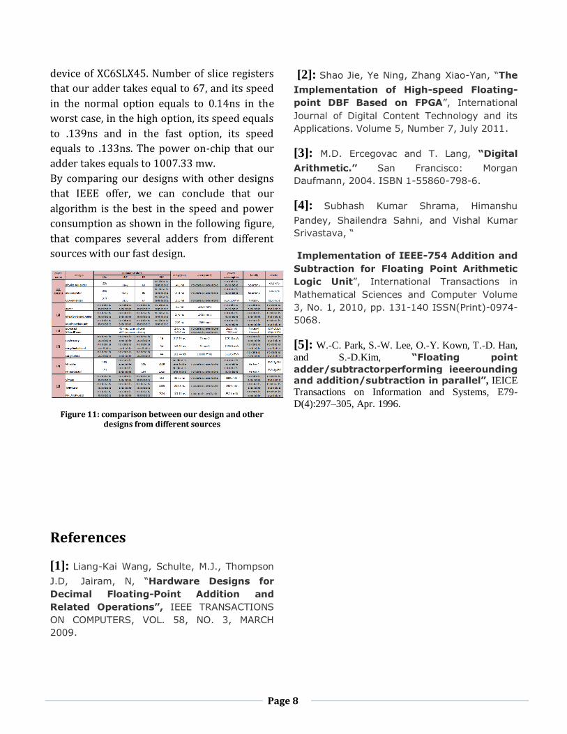
By comparing our designs with other designs
that IEEE offer, we can conclude that our
algorithm is the best in the speed and power
consumption as shown in the following figure,
that compares several adders from different
sources with our fast design.
Figure 11: comparison between our design and other designs from different sources
References
[1]: Liang-Kai Wang, Schulte, M.J., Thompson
J.D, Jairam, N, “Hardware Designs for
Decimal Floating-Point Addition and
Related Operations”, IEEE TRANSACTIONS
ON COMPUTERS, VOL. 58, NO. 3, MARCH
2009.
[2]: Shao Jie, Ye Ning, Zhang Xiao-Yan, “The
Implementation of High-speed Floating-
point DBF Based on FPGA”, International
Journal of Digital Content Technology and its
Applications. Volume 5, Number 7, July 2011.
[3]: M.D. Ercegovac and T. Lang, “Digital
Arithmetic.” San Francisco: Morgan
Daufmann, 2004. ISBN 1-55860-798-6.
[4]: Subhash Kumar Shrama, Himanshu
Pandey, Shailendra Sahni, and Vishal Kumar
Srivastava, “
Implementation of IEEE-754 Addition and
Subtraction for Floating Point Arithmetic
Logic Unit”, International Transactions in
Mathematical Sciences and Computer Volume
3, No. 1, 2010, pp. 131-140 ISSN(Print)-0974-
5068.
[5]: W.-C. Park, S.-W. Lee, O.-Y. Kown, T.-D. Han,
and S.-D.Kim, “Floating point
adder/subtractorperforming ieeerounding and addition/subtraction in parallel”, IEICE Transactions on Information and Systems, E79-
D(4):297–305, Apr. 1996.