impacts in the structural design of the 2014 revision of
TRANSCRIPT

© 2015 IBRACON
Impacts in the structural design of the 2014 revision of the brazilian standard ABNT NBR 6118
Impactos no projeto estrutural da versão 2014 da norma brasileira ABNT NBR 6118
a Universidade Federal do Rio de Janeiro, Escola Politécnica, Programa de Projeto de Estruturas, Rio de Janeiro, RJ, Brasil;b Universidade Federal do Rio de Janeiro, Escola Politécnica, Departamento de Estruturas, Rio de Janeiro, RJ, Brasil.
Received: 22 Dec 2014 • Accepted: 25 May 2015 • Available Online: 7 Aug 2015
Abstract
Resumo
With the issuing of the 2014 version of the Brazilian Standard ABNT NBR 6118 – Design of Concrete Structures, several procedures followed in the design offices shall be altered. The purpose of this paper is to furnish data to the designers, in order to facilitate the transition to the new version of the Standard. A summary of some of the main modifications with direct impact in the design is presented, being shown, among oth-ers, the topics: characteristics of the concretes of class up to C90, including the new stress-strain diagrams and respective simplification criteria for these diagrams, the new deformation domains, the values of design tensile stresses in concrete and the new criteria for limiting the depth of the neutral axis; new design criteria for designing and detailing of special elements, including the application of strut-and-tie models; new design criteria, minimum dimensions and detailing criteria for columns, walls and slabs; new criteria for considering global imperfections; new criteria for considering creep and shrinkage; new values for minimum reinforcement in pure bending; new expressions for evaluating the elasticity modulus of concrete. A new table for the design of concrete sections under pure bending is furnished, and new diagrams for designing rectangular sections under bending with compression forces are presented.
Keywords: brazilian standard, structural concrete, design, detailing.
Com a promulgação da versão 2014 da Norma Brasileira ABNT NBR 6118 – Projeto de Estruturas de Concreto, diversos procedimentos adotados nas empresas de projeto deverão ser alterados. O objetivo deste trabalho é fornecer subsídios aos projetistas, de forma a facilitar a transição para a nova versão da Norma. É apresentado um resumo de algumas das principais alterações que tem impacto direto no projeto, sendo abordados, entre outros, os temas: características dos concretos de classe até C90, incluindo os novos diagramas tensão-deformação e respectivos critérios de simplificação destes diagramas, os novos domínios de deformação, os valores de tensão de tração de cálculo no concreto e os novos critérios de limitação da profundidade da linha neutra; novos critérios de dimensionamento e detalhamento de elementos especiais, inclusive com a apli-cação de Modelos Biela-Tirante; novos critérios de projeto, dimensões mínimas e detalhamento de pilares, pilares-parede e lajes; novos critérios para a consideração de imperfeições globais; novos critérios para a consideração de retração e fluência; novos valores para a armadura mínima de peças em flexão simples; novas expressões para a avaliação do módulo de elasticidade do concreto. É também fornecida uma nova tabela de dimensionamento na flexão simples e apresentados novos ábacos para o dimensionamento de seções retangulares na flexão composta reta.
Palavras-chave: norma brasileira, concreto estrutural, dimensionamento, detalhamento.
R. M. CERUTTI a
S. H. C. SANTOS b
Volume 8, Number 4 (August 2015) p. 547-566 • ISSN 1983-4195http://dx.doi.org/10.1590/S1983-41952015000400008
548 IBRACON Structures and Materials Journal • 2015 • vol. 8 • nº 4
Impacts in the structural design of the 2014 revision of the brazilian standard ABNT NBR 6118
1. Introduction
After several months of intense work of the Committee of Study charged of its revision, the 2014 revision of the Brazilian Stan-dard ABNT NBR 6118 – Design of Concrete Structures [1] was finally issued. This revision puts the ABNT NBR 6118 in the same level of actualization of the more respected international Stan-dards, reflecting the disposition of the Brazilian Association of Technical Standards (ABNT) and also of the Brazilian technical community of achieving an elevated quality level in the design and construction of concrete structures. Among several other im-portant modifications, the range of application of the ABNT NBR 6118 criteria is now extended from the Concrete Class C50 up to the Class C90. A brief summary of some of these new criteria is presented herein. Some of these new criteria were already pre-sented by SANTOS [2].
2. Characteristics of the concrete
2.1 Modulus of Elasticity
The advance towards better understanding of the properties of the concrete, achieved in the last years, allowed to a more precise definition of the concrete modulus of elasticity, in the absence of specific tests for its determination.An estimative of the tangent modulus of elasticity, to be used, for instance, in the evaluation of prestressing losses, is given by:- for fck from 20 MPa to 50 MPa;
(1)E ci = aE . 5600 ckf
- for fck from 55 MPa to 90 MPa:
(2)E ci = 21.5 . 10 3 . aE . 3/1
ck 25.110
f÷ø
öçè
æ+
The parameter αE depends on the base rock of the used gravel:αE = 1.2 for basalt and diabase;αE = 1.0 for granite and gneiss;αE = 0.9 for calcarium;αE = 0.7 for arenite.An estimative for the secant modulus of elasticity, to be used in the evaluation of the general behavior of a structural member or of a specific transversal section is given by:
(3)E cs = ai . E ci
(4)ai = 0.8 + 0.2 80ckf = 1.0
The two moduli converge for the same value with the increase of the concrete strength, as long as the initial part of the stress-strain diagrams becomes closer to a straight line. A graphical visualization of the variation of these two parameters (for αE = 1.0) is presented in Figure 1.
2.2 Stress-strain curves
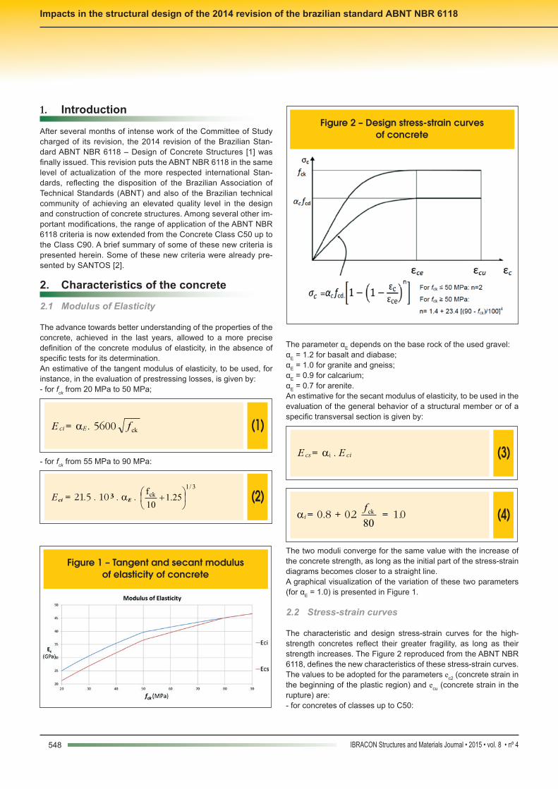
The characteristic and design stress-strain curves for the high-strength concretes reflect their greater fragility, as long as their strength increases. The Figure 2 reproduced from the ABNT NBR 6118, defines the new characteristics of these stress-strain curves.The values to be adopted for the parameters ec2 (concrete strain in the beginning of the plastic region) and ecu (concrete strain in the rupture) are:- for concretes of classes up to C50:
Figure 1 – Tangent and secant modulus of elasticity of concrete
Figure 2 – Design stress-strain curves of concrete

549IBRACON Structures and Materials Journal • 2015 • vol. 8 • nº 4
R. M. CERUTTI | S. H. C. SANTOS
(5)ec2 = 2.00/00
(6)ecu = 3.50/00
- for concretes of classes from C50 to C90:
(7)ec2 = 2.00/00 + 0.0850/00.(fck - 50)0,53
(8)ecu = 2.60/00 + 350/00.[(90 - fck)/100]4
The parameters n, ec2 e ecu are graphically shown in Figure 3.
2.3 Tensile strength
In the absence of specific tests, the values of average tensile strengths shall be evaluated with the expressions:- for concretes with fck ≤ 50 MPa:
(9)fct,m = 0.3 fck 2/3
- for concretes with fck 50 MPa up to 90 MPa:
(10)fct,m = 2.12 ln (1 + 0.11 fck)
It shall be noticed that the concrete tensile strengths increases more slowly with respect to the increase of the concrete compres-sion strengths. A graphical representation of these variations is given in Figure 4.
3. Design for bending and axial forces
3.1 New deformation criteria in the ultimate limit state for the design
The Figure 17.1 of the Standard has been revised, being now de-fined as reproduced in Figure 5.
3.2 Simplificationofthestress-strainconcretecurves
Considering the typical fragility of the concretes of class superior
Figure 3 – Variation of parameters n, e e e c2 cu Figure 4 – Average concrete tensile strength
Figura 5 – Deformation regions in the ultimate limit state
550 IBRACON Structures and Materials Journal • 2015 • vol. 8 • nº 4
Impacts in the structural design of the 2014 revision of the brazilian standard ABNT NBR 6118
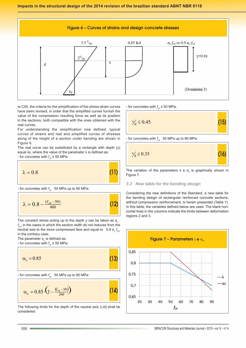
to C50, the criteria for the simplification of the stress-strain curves have been revised, in order that the simplified curves furnish the value of the compression resulting force as well as its position in the sections, both compatible with the ones obtained with the real curves.For understanding the simplification now defined, typical curves of strains and real and simplified curves of stresses along of the height of a section under bending are shown in Figure 6.The real curve can be substituted by a rectangle with depth (y) equal λx, where the value of the parameter λ is defined as:- for concretes with fck ≤ 50 MPa:
(11)8.0=l
- for concretes with fck 50 MPa up to 90 MPa:
(12)400
)50f( ck8.0-
-=l
The constant stress acting up to the depth y can be taken as αc . fcd, in the cases in which the section width do not reduces from the neutral axis to the more compressed face and equal to 0,9 αc fcd, in the contrary case.The parameter αc is defined as:- for concretes with fck ≤ 50 MPa:
(13)85.0c =a
- for concretes with fck 50 MPa up to 90 MPa:
(14) ( )( )200
50fc
ck185.0-
-×=a
The following limits for the depth of the neutral axis (x/d) shall be considered:
- for concretes with fck ≤ 50 MPa:
(15) 45.0dx £
- for concretes with fck 50 MPa up to 90 MPa:
(16) 35.0dx £
The variation of the parameters λ e αc is graphically shown in Figure 7.
3.3 New table for the bending design
Considering the new definitions of the Standard, a new table for the bending design of rectangular reinforced concrete sections, without compression reinforcement, is herein presented (Table 1). In this table, the variables defined below are used. The black hori-zontal lines in the columns indicate the limits between deformation regions 2 and 3.
Figure 6 – Curves of strains and design concrete stresses
Figure 7 – Parameters g e a c

551IBRACON Structures and Materials Journal • 2015 • vol. 8 • nº 4
R. M. CERUTTI | S. H. C. SANTOS
(17)
ydz
ds
cd
dmdzx
fkd
MA
fdb
MK
d
zk
d
xk
..;
..;;
2====
Where:x – neutral axis depth;d – effective section height;b – section width;z – level arm in bending;Md – design value of the bending moment;fcd – design value of concrete strength;fyd – design value of yielding stress of the reinforcing steel. It shall be noticed that this table can be also applied for the design of sections with compression reinforcement. In this case, the table can be used for the evaluation of the part of the tensile reinforce-
ment in equilibrium with the compression resisted by the concrete. The remaining part of the tensile reinforcement, equilibrated by the compression reinforcement, can be evaluated in the usual way.
3.4 New table for minimum reinforcement in bending
The Table 17.3 of ABNT NBR 6118 has been completely reformu-lated and it is partially reproduced in Table 2.
3.5 New design charts for eccentric compression
New design charts for eccentric compression have been developed for the concretes of class superior to C50. Due to the new defini-tions of ABNT NBR 6118, the design charts for these high-strength concretes present numerical values very different from the ones ob-tained with the charts developed for concretes of class up to C50.
Table 1 – Bending design
fck ≤ 50MPa 60 MPa 70 MPa 80 MPa 90 MPa
εcu and klim23 3.500 0.259 2.884 0.224 2.656 0.210 2.604 0.207 2.600 0.206
λ e αc 0.800 0.850 0.775 0.808 0.750 0.765 0.725 0.723 0.700 0.680
kx kz Kmd kz Kmd kz Kmd kz Kmd kz Kmd
0.02 0.992 0.013 0.992 0.012 0.993 0.011 0.993 0.010 0.993 0.009
0.04 0.984 0.027 0.985 0.025 0.985 0.023 0.986 0.021 0.986 0.019
0.06 0.976 0.040 0.977 0.037 0.978 0.034 0.978 0.031 0.979 0.028
0.08 0.968 0.053 0.969 0.049 0.970 0.045 0.971 0.041 0.972 0.037
0.10 0.960 0.065 0.961 0.060 0.963 0.055 0.964 0.050 0.965 0.046
0.12 0.952 0.078 0.954 0.072 0.955 0.066 0.957 0.060 0.958 0.055
0.14 0.944 0.090 0.946 0.083 0.948 0.076 0.949 0.070 0.951 0.063
0.16 0.936 0.102 0.938 0.094 0.940 0.086 0.942 0.079 0.944 0.072
0.18 0.928 0.114 0.930 0.105 0.933 0.096 0.935 0.088 0.937 0.080
0.20 0.920 0.125 0.923 0.115 0.925 0.106 0.928 0.097 0.930 0.089
0.22 0.912 0.136 0.915 0.126 0.918 0.116 0.920 0.106 0.923 0.097
0.24 0.904 0.148 0.907 0.136 0.910 0.125 0.913 0.115 0.916 0.105
0.26 0.896 0.158 0.899 0.146 0.903 0.135 0.906 0.123 0.909 0.112
0.28 0.888 0.169 0.892 0.156 0.895 0.144 0.899 0.132 0.902 0.120
0.30 0.880 0.180 0.884 0.166 0.888 0.153 0.891 0.140 0.895 0.128
0.32 0.872 0.190 0.876 0.175 0.880 0.162 0.884 0.148 0.888 0.135
0.34 0.864 0.200 0.868 0.185 0.873 0.170 0.877 0.156 0.881 0.143
0.35 0.860 0.205 0.864 0.189 0.869 0.174 0.873 0.160 0.878 0.146
0.37 0.852 0.214 – – – – – – – –
0.39 0.844 0.224 – – – – – – – –
0.41 0.836 0.233 – – – – – – – –
0.43 0.828 0.242 – – – – – – – –
0.45 0.820 0.251 – – – – – – – –
Table 2 – Values of de ρmin (As,min/Ac) (%) as a function of fck
fck 20 30 40 50 60 70 80 90
ρmin 0.150 0.150 0.179 0.208 0.219 0.233 0.245 0.256

552 IBRACON Structures and Materials Journal • 2015 • vol. 8 • nº 4
Impacts in the structural design of the 2014 revision of the brazilian standard ABNT NBR 6118
These new charts can be obtained as presented by CERUTTI [3]. In this work, it has been shown that, for the concretes of class superior to C50, the use of the rectangular block of stresses is not applicable to the cases of small eccentricities, since in these cases the results are excessively conservative. This leads to the obliga-tory consideration of the real strain-stress curves of the concrete. In the Figures 8 and 9, a comparison is presented between design charts drawn for concretes of class up to C50 and for concrete class C90, respectively (both for the rectangular section called
Type 2, with reinforcement uniformly distributed in its perimeter). The design charts use the parameters η, µ e ω (respectively di-mensionless normal forces and bending moments and mechanical reinforcement ratio), as defined below:
(18)
cd
yds
cd
d
cd
d
f.h.b
f.A;
f.h.b
M;
f.h.b
N=== wmh
2
Figure 8 – Dimensionless design chart – Type 2 – d'/h = 0,10 – C50
Figure 9 – Dimensionless design chart – Type 2 – d'/h = 0,10 – C90

553IBRACON Structures and Materials Journal • 2015 • vol. 8 • nº 4
R. M. CERUTTI | S. H. C. SANTOS
In the hyperlink mentioned as a reference in CERUTTI [3], this work can be directly accessed, where several design charts can be found, developed for several distributions of reinforcement. Sever-al examples of application of the charts can be also found therein.
4. Design with strut-and-tie models
The Figure 22.1 of ABNT NBR 6118, reproduced in Figure 10, shows several typical situations of D regions, of geometrical dis-continuity of stresses or of application of concentrated loads, which can be analyzed using strut-and-tie models. The 2014 revision of the Standard defines new criteria for the verification of concrete stresses in these special regions.The stress limits fcd1, fcd2 e fcd3. are defined as follows.
(19)fcd1 = 0.85 αv2 fcd
(20)fcd2 = 0.60 αv2 fcd
(21)fcd3 = 0.72 αv2 fcd
Where:αV2 = 1 - fck/250The limit fcd1 is applicable to the verification of regions with transversal compression stresses or without transversal tensile stresses and in nodes where only compression struts converge. The limit fcd2 is applicable to the verification of regions with tensile transversal stresses and in nodes where two or more tensioned ties converge. The limit fcd3 is applicable to nodes where only one tensioned tie converges.The Figure 11 presents the application of these three compression stress limits in the case of the analysis of a simply supported beam.Design and detailing of columns and structural walls
5.1 Minimum dimensions
The minimum value for the thickness of columns and structural walls is from now on 14 cm. When this thickness is inferior to 19 cm, a correction coefficient γn for adjusting the loads is applicable, to be multiplied by the safety factors for loads γf, as defined below (b is the thickness of the column in cm):
(22)γn = 1,95 – 0,05b
Some important changes have been included in section 11.3.3.4.1 of the Standard, regarding the evaluation of global geometric im-perfections in buildings. The Figure 12 shows a scheme illustrating the effects of these global imperfections.The range of variation of the coefficient q1 is now, for framed
Figure 10 – Typical situations of Regions D

554 IBRACON Structures and Materials Journal • 2015 • vol. 8 • nº 4
Impacts in the structural design of the 2014 revision of the brazilian standard ABNT NBR 6118
structures and for the evaluation of local imperfections, from q1min = 1/300 to q1max = 1/200.It is now necessary an investigation of the necessity of superposi-tion of effects of global imperfections and wind. This superposition will be necessary whether the smaller of the two effects, measured according the global resulting moments at the base of the struc-ture, is superior to 30% of the greater effect. In this comparison, the building inclination may be evaluated considering the angle q1, and not the angle q1min.When the superposition is necessary, and wind effects are the pre-dominant ones, these wind effects shall be combined with global imperfections corresponding to θ1, not being considered the angle θ1mín. If the effects of global imperfections are predominant, the angle θ1mín shall be taken into account.
6. Design of slabs
6.1 Minimum thickness of slabs
Important changes were introduced in the definition of the mini-mum thickness of slabs, in the section 13.2.4.1 of the Standard, as follows:n 7 cm for roof slabs not cantilevered;n 8 cm for floor slabs not cantilevered;n 10 cm for cantilevers. In order to assure a greater reliability for the cantilevered slabs with thickness smaller than 19 cm, a correction coefficient γn for adjust-ing the loads is applicable, to be multiplied by the safety factors for loads γf, which have the same numerical expression defined
in Equation (22) for slender columns, with the substitution in the equation of b by h, slab thickness.
6.2 Detailing of Slabs
According to section 19.3.3.2 of ABNT NBR 6118, it is now neces-sary a minimum negative (superior) reinforcement, even in the sup-
Figure 11 – Regions for the application of the concrete compression stresses
Figure 12 – Scheme of global imperfections

555IBRACON Structures and Materials Journal • 2015 • vol. 8 • nº 4
R. M. CERUTTI | S. H. C. SANTOS
ports of slabs (usually beams) which does not present continuity with adjacent slabs, but with elastic connection with the support elements.This negative reinforcement shall comply with the minimum re-inforcement ratio ρs ≥ 0.67 ρmin, according to the Table 19.1 of the Standard. This reinforcement shall cover at least 0.15 of the smaller span of the analyzed slab, from the face of the support.It is now necessary, in slabs reinforced in one or two directions and for which transversal reinforcement is not necessary, that all the positive reinforcement should placed up to the supports, with 4 cm beyond the theoretical axis of the supports. This require-ment may be dispensed if an explicit evaluation on the increases of the reinforcement due to the torsional moments in the slabs would be done.
7. Detailing of deep beams
The section 22.4.4.1 of the Standard defines new criteria for the detailing of deep beams. The positive (inferior) reinforcement shall be placed in a strip of height up to 0.15 h (h – effective height of the deep beam).The negative reinforcement AS shall be distributed considering three strips in the effective height h, which shall be smaller than the theoretical beam span (3 ≥ /h ≥ 1):
(23a)Superior 20% of h: AS1 = ( /2h - 0.50) . AS
(23b)Central 60% of h: AS2 = (1.50 - /2h) . AS
(23c)Inferior 20% of h: AS3 = 0
The minimum vertical and horizontal reinforcement is of 0,075% b (thickness), per face, per meter.
8. Creep and shrinkage
Important changes have been introduced in the criteria for the evaluation of effects of creep and shrinkage, reflecting the evolu-tion of the knowledge on these subjects in the last years. The coef-ficients defined in the Table 8.2 of the Standard, and reproduced next in Table 3, considers now different values for the creep coef-ficients for concretes with fck ≥ 50 MPa. In the revision 2014 of the Standard, regarding the revision of 2007, the values of creep are reduced, mainly for concretes with fck ≥ 50 MPa, but there is an important increase in the shrinkage coef-ficients. It should be noticed that the more detailed criteria defined in the Appendix A of the Standard were also modified.
9. Conclusion
Some of the main changes introduced in the 2014 revision of ABNT NBR 6118, which will have direct impact in the safety verifications of reinforced concrete structures have been shortly summarized herein. It shall be noticed that, differently from the previous revisions, this one has immediate compulsory appli-cation after its issuing. New work processes, as the obligatory verification of the design by an independent design office, of all the structural projects, shall be also implemented. In this way, an immediate adaptation of the criteria currently applied in the
Table 3 – Characteristic superior values of shrinkage εcs(t∞,t0) and creep j(t∞,t0)
Average realive humidity% 40 55 75 90
Equivalent thickness2Ac/u
cm20 60 20 60 20 60 20 60
j(t∞,t0)Concrete of class C20
to C45
t0
days
5 4.6 3.8 3.9 3.3 2.8 2.4 2.0 1.9
30 3.4 3.0 2.9 2.6 2.2 2.0 1.6 1.5
60 2.9 2.7 2.5 2.3 1.9 1.8 1.4 1.4
j(t∞,t0)Concrete 0f class C50
to C90
5 2.7 2.4 2.4 2.1 1.9 1.8 1.6 1.5
30 2.0 1.8 1.7 1.6 1.4 1.3 1.1 1.1
60 1.7 1.6 1.5 1.4 1.2 1.2 1.0 1.0
εcs(t∞,t0)0/00
5 - 0.53 - 0.47 - 0.48 - 0.43 - 0.36 - 0.32 - 0.18 - 0.15
30 - 0.44 - 0.45 - 0.41 - 0.41 - 0.33 - 0.31 - 0.17 - 0.15
60 - 0.39 - 0.43 - 0.36 - 0.40 - 0.30 - 0.31 - 0.17 - 0.15

556 IBRACON Structures and Materials Journal • 2015 • vol. 8 • nº 4
Impacts in the structural design of the 2014 revision of the brazilian standard ABNT NBR 6118
design practice of the engineering firms shall be adopted, consid-ering the new requirements of the revision 2014 of the Brazilian Standard.
10. Bibliographic references
[1] ASSOCIAÇÃO BRASILEIRA DE NORMAS TÉCNICAS (ABNT). NBR 6118. Projeto de estruturas de concreto – Pro-cedimento. Rio de Janeiro. 2014 (in Portuguese).
[2] SANTOS, S.H.C.- Os Concretos de Alta Resistência na NBR 6118:2014, Revista Concreto & Construções nº 73, pg. 52-57, January/Marçh 2014 (in Portuguese).
[3] CERUTTI, R. M. B. – Análise do Comportamento do Con-creto de Alta Resistência na Flexão Composta com Base na NBR 6118:2014, Graduation Monography, Polytechnic School, UFRJ, 2014. Available in:http://monografias.poli.ufrj.br/monografias/monopoli10010812.pdf (in Portuguese).