impact of fire on steel reinforcement of r.c.c structures · the specimens for testing were sri tmt...
TRANSCRIPT

Page 1466
Impact of Fire on Steel Reinforcement of R.C.C Structures Saddam Hussain
M.Tech Student,
Tudi Narasimha Reddy Institute of Technology and
Sciences.
K.Harish Kumar, M.Tech
Assistant Professor,
Tudi Narasimha Reddy Institute of Technology and
Sciences.
Abstract:
With the increased incidents of major fires in
buildings; assessment, repairs and rehabilitation of fire
damaged structures has become a topical interest. This
is a specialized field involves expertise in many areas
like concrete technology, material science and testing,
structural engineering, repair materials and techniques
etc. Research and developmental efforts are being
carried out in this area and other related disciplines. In
this topic the experience of real life problems are
presented which add immense value to this. The
experimentation has been done to find out the impact
of the fire on reinforcement steel bars by heating the
bars to 100°,300°,600°,900° centigrade of 6 samples
each. The heated samples are rapidly cooled by
quenching in water and normally by air cooling. The
change in the mechanical properties are studied using
universal testing machine (UTM) and the microscopic
study of grain size and grain structure is studied by
scanning electron microscope (SEM).
1.Introduction:
With the increased incidents of major fires and fire
accidents in buildings; assessment, repair and
rehabilitation of fire damaged structures has become a
topical interest. This specialized field involves
expertise in many areas like concrete technology,
material science and testing, structural engineering,
repair materials and techniques etc. Research and
development efforts are being carried out in these
related disciplines. Any structure can undergo fire
accident, but because of this the structure cannot be
denied neither abandoned. To make a structure
functionally viable after the damage due to fire has
become a challenge for the civil engineering
community. The problem is where to start and how to
proceed.
It is vitally important that we create buildings and
structures that protect both people and property as
effectively as possible. Annual statistics on losses
caused by fires in homes and elsewhere make for some
unpleasant readings and sadly through these events we
learn more about fire safety design.
1.1 EXPERIENCE OF FIRES:
Fig 1.1: fire damaged slab
Fig 1.2: concreting of fire damaged slab
1. Most of the structures were repaired. Of those that
were not, many could have been but were demolished
for reasons other than the damage sustained.
2. Almost without exception, the structures performed
well during and after the fire.

Page 1467
1.2 WHAT HAPPENS TO CONCRETE IN A
FIRE:
Fires are caused by accident, energy sources or natural
means, but the majority of fires in buildings are caused
by human error. Once a fire starts and the contents
and/or materials in a building are burning, then the fire
spreads via radiation, convection or conduction with
flames reaching temperatures of between 600°C and
1200°C. Harm is caused by a combination of the
effects of smoke and gases, which are emitted from
burning materials, and the effects of flames and high
air temperatures.
2. EXPERIMENTAL WORK:
2.1 INTRODUCTION:
The specimens for testing were Sri TMT bar of 12mm
diameter. 54 bars were cut to 40 cm size. 6 Specimens
were tested for the mechanical properties using UTM
before heating at normal temperature and the
properties were tabulated. 12 specimens each were
heated in the electrical furnace at 100°, 300°, 600° and
900°C for an hour without any disturbance. After
heating, out of 12 specimens for each temperature 6
samples were quenched in water for rapid cooling and
the other 6 were kept aside for normal cooling at
atmospheric temperature. These specimens later were
tested for mechanical properties with UTM and
microstructure study using SEM.
2.2 EQUIPMENT:
i. Universal Testing Machine
ii. Scanning Electron Microscope
iii. Electrical Furnace
2.3 UTM TESTING:
The 12mm steel bar is cut to a length of 40 cm and
gave a gauge length of 60mm. The specimen is fixed
on the machine and the required data on the computer
is given. Test is conducted at a load rate of 300 kg/min
for all the specimens. An extensometer is fixed to the
specimen during the test to read the elongation. The
data of the test is noted in computer during the test by
default s it is setup.
The graph of load versus deformation and load versus
elongation is drawn on the computer. After the test all
the other parameters like ultimate load, maximum
extension in mm, area in mm2, ultimate stress,
elongation in percent, reduction in in area, young’s
modulus, yield stress, .1% and .2% proff stress and
many other parameters can be observed.
Fig 2.1: UTM testing setup
Fig 2.2: Screenshot of the result of tensile test using
UTM
2.4: Tensile testing:
Tensile testing is performed in accordance with ASTM
D-638 as well as ISO 527 combined tensile and
flexural procedure. Tensile properties are the most
important single indication of strength in a material.
Page 1468
The force needed to pull the specimen apart is
determined, along with how much the material
stretches before it breaks. The tensile modulus is the
ratio of stress to strain below the proportional limit of
the material. This is the most useful tensile data as
parts should be designed to accommodate stresses to a
degree well below it.
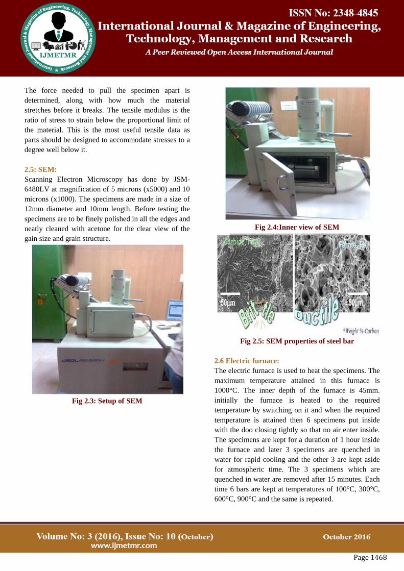
2.5: SEM:
Scanning Electron Microscopy has done by JSM-
6480LV at magnification of 5 microns (x5000) and 10
microns (x1000). The specimens are made in a size of
12mm diameter and 10mm length. Before testing the
specimens are to be finely polished in all the edges and
neatly cleaned with acetone for the clear view of the
gain size and grain structure.
Fig 2.3: Setup of SEM
Fig 2.4:Inner view of SEM
Fig 2.5: SEM properties of steel bar
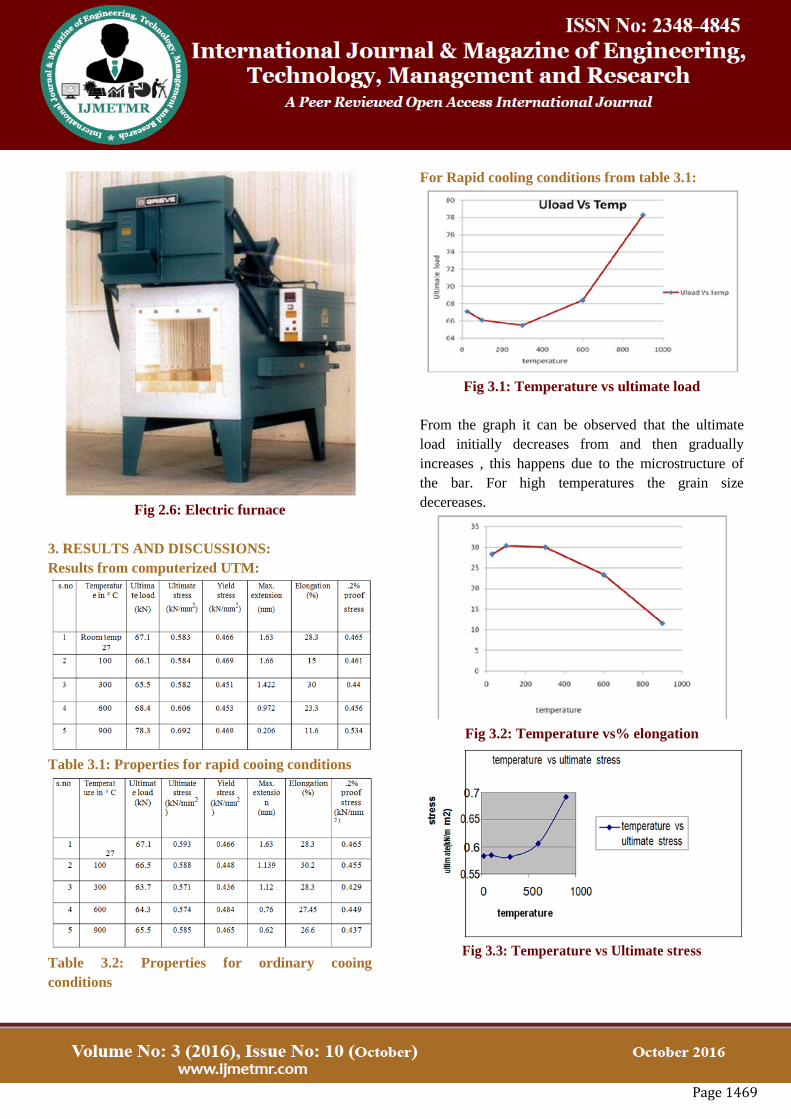
2.6 Electric furnace:
The electric furnace is used to heat the specimens. The
maximum temperature attained in this furnace is
1000°C. The inner depth of the furnace is 45mm.
initially the furnace is heated to the required
temperature by switching on it and when the required
temperature is attained then 6 specimens put inside
with the doo closing tightly so that no air enter inside.
The specimens are kept for a duration of 1 hour inside
the furnace and later 3 specimens are quenched in
water for rapid cooling and the other 3 are kept aside
for atmospheric time. The 3 specimens which are
quenched in water are removed after 15 minutes. Each
time 6 bars are kept at temperatures of 100°C, 300°C,
600°C, 900°C and the same is repeated.
Page 1469
Fig 2.6: Electric furnace
3. RESULTS AND DISCUSSIONS:
Results from computerized UTM:
Table 3.1: Properties for rapid cooing conditions
Table 3.2: Properties for ordinary cooing
conditions
For Rapid cooling conditions from table 3.1:
Fig 3.1: Temperature vs ultimate load
From the graph it can be observed that the ultimate
load initially decreases from and then gradually
increases , this happens due to the microstructure of
the bar. For high temperatures the grain size
decereases.
Fig 3.2: Temperature vs% elongation
Fig 3.3: Temperature vs Ultimate stress

Page 1470
Fig 3.4: .2%Proff stress vs temperature
For ordinary cooling conditions from table 3.2:
Fig 3.5: Temperature vs Ultimate load
From the Fig 3.5, the ultimate load carrying ot the
specimen was reduced drom the specimen before
heating.
Fig 3.6: Temperature vs Ultimate stress
Fig 3.7: temperature vs elongation
Fig 3.8: Temperature vs yeild Stress
Fig.3.9: Temperature vs .2% Proof stress
SEM Analyses:
Pictures are taken at the magnification of 10 microns
and 5 microns.

Page 1471
Fig 3.10: 100° C Ordinary cooling at magnification
of 5 microns
Fig 3.11: 100° C Ordinary cooling at magnification
of 10 microns
Fig 3.12: 300° C Ordinary cooling at magnification
of 10 microns
Fig 3.14: 300° C Rapid cooling at magnification of
10 microns
Fig 3.14: 900° C ordinary cooling at 10 micron
4.CONCLUSION:
i. The impact of fire on the reinforcement bars heated
at various temperatures of 100° C, 300° C, 600° C,
900° C, cooled rapidly by quenching in water and
normally cooled in the atmospheric temperature were
studied and it is observed that the ductility of rapidly
cooled bars after heating to high temperature to 900 °
C.
ii.Studying the characteristic changes in the
mechanical properties of the bars by Tensile strength
testing using Universal Testing Machine shows that
the increase in ultimate load and decrease in
percentage elongation of the specimen which mean
that there is significant decrease in ductility of the
specimen.
Page 1472
iii. Study of micro structure of the bars using Scanning
Electron Microscope (SEM) also shows that the
microstructure of highly heated specimens varies
without varying the chemical composition which
would have negative impact on the structure.
References:
1.Roberto Felicetti, DIS – Politecnico di Milano, P.za
L. da Vinci 32, 20133 Milano,Italy 17 The drilling
resistance test for the assessment of fire damaged
concrete. April 2006
2. N.R. ShortU, J.A. Purkiss, S.E. Guise School of
Engineering and Applied Science, Aston Uni¨ersity,
Aston Triangle, Birmingham B4 7ET, UK Assessment
of fire damaged concrete using colour image analysis.
Received 30 August 1999;
3.Roberto Felicetti Department of Structural
Engineering (DIS), Politecnico di Milano, Piazza
Leonardo da Vinci 32, 20133 Milano, Italy. New NDT
techniques for the assessment of fire-damaged
concrete structures. Matteo Colombo, September 2006
4.M.A Riley,Msc. Possible new method for the
assessment of fire-damaged structures. Sir william
halcrow and patners- 1991
5.Chi-Sun poon, Salman Azhar, Mike Anson, Yuk-
Lung Wong. Strength and durability recovery of fire-
damaged concrete after post-fire-curing. Honkong
polytechnic university-2000
6.R.Folic, V.Radojanin, M.Malesev. The assessment
of the structure of Novi Sad open University damaged
in fire. University of NoviSad, Yugoslavia-2002
7.Jisn-Zuusng Xiao, Jie Li, Zhan-Fei Huang Fire
response of high-performance concrete frames and
their post-fire seismic performance. ACI
8.Wei-Ming, T.D. Lin, L.J.Powers-Couche.
Microstructure of fire-damaged concrete.ACI
9.Dr.A.Kumar, V.Kumar, Behaviour of RCC Beams
after Exposure to Elevated Temperatures.
10.Jones, C.D. Repair of fire damaged structures.
Source: Elsevier Applied Science Publications, p 237-
251, 1986.
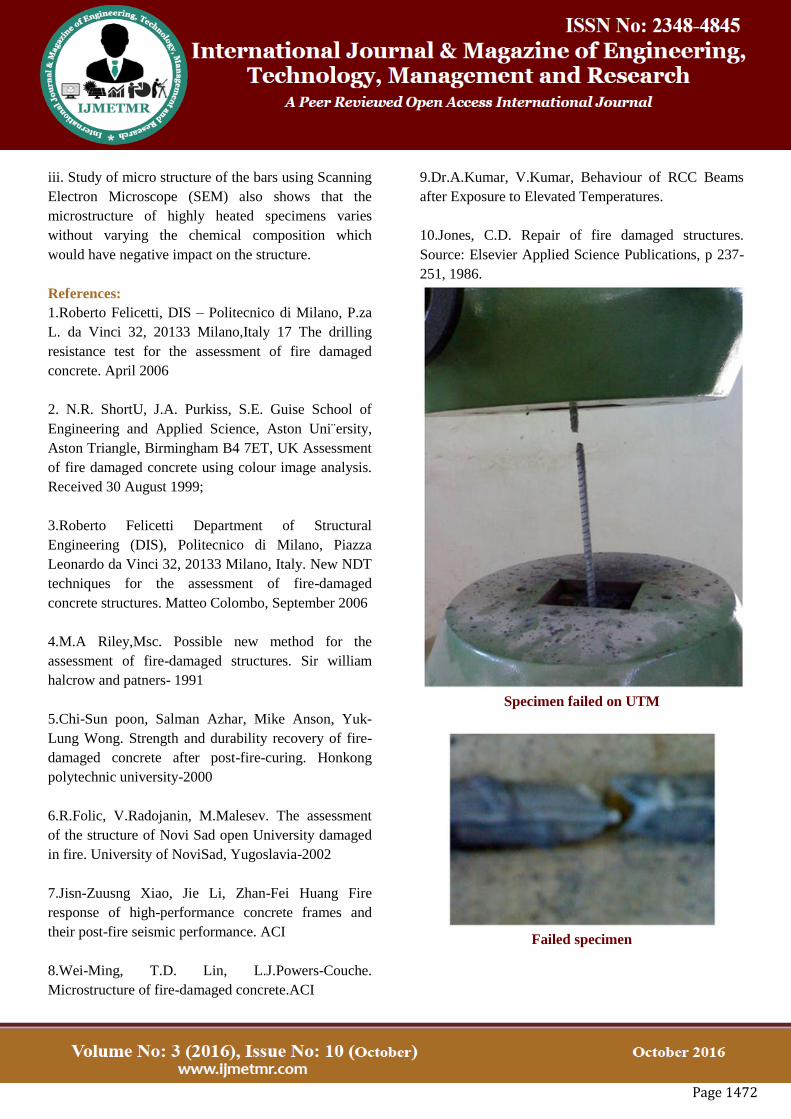
Specimen failed on UTM
Failed specimen
Page 1473
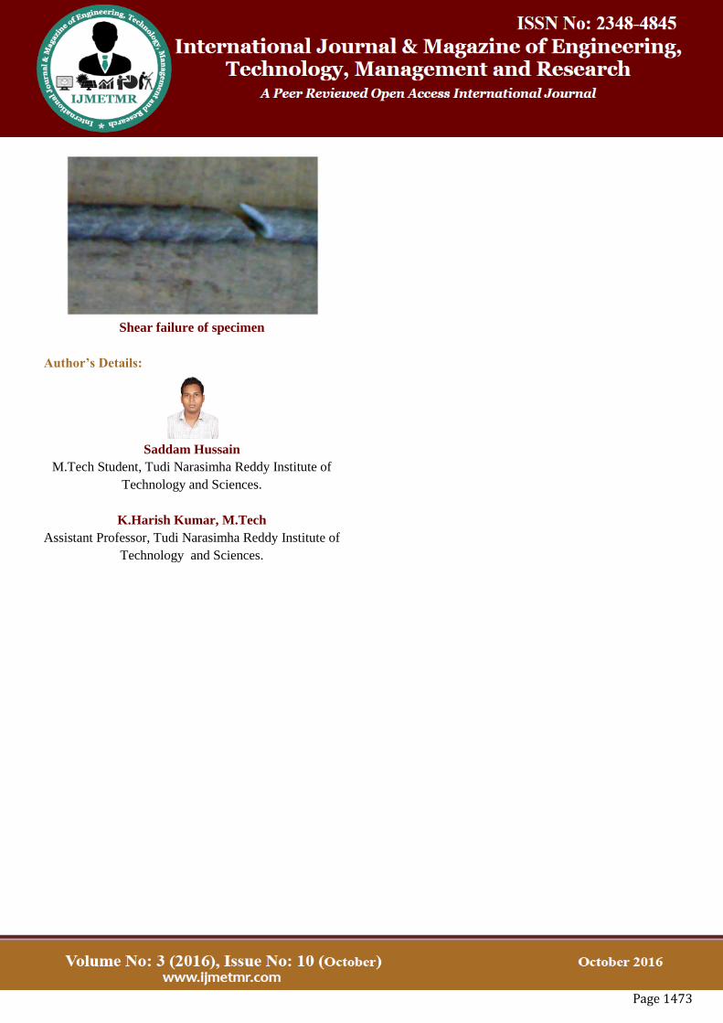
Shear failure of specimen
Author’s Details:
Saddam Hussain
M.Tech Student, Tudi Narasimha Reddy Institute of
Technology and Sciences.
K.Harish Kumar, M.Tech
Assistant Professor, Tudi Narasimha Reddy Institute of
Technology and Sciences.