impact of dispersion on pulse dynamics in chirped-pulse ... · impact of dispersion on pulse...
TRANSCRIPT

Appl Phys B (2012) 107:263–274DOI 10.1007/s00340-012-5010-0
Impact of dispersion on pulse dynamics in chirped-pulse fiberlasers
M. Baumgartl · B. Ortaç · J. Limpert · A. Tünnermann
Received: 5 March 2012 / Published online: 26 April 2012© Springer-Verlag 2012
Abstract We report on a systematic study of an environ-mentally stable mode-locked Yb-doped fiber laser operatingin the chirped-pulse regime. The linear cavity chirped-pulsefiber laser is constructed with a saturable absorber mirror asnonlinear mode-locking mechanism and a nonlinearity-freetransmission-grating-based stretcher/compressor for disper-sion management. Mode-locked operation and pulse dynam-ics from strong normal to strong anomalous total cavitydispersion in the range of +2.5 to −1.6 ps2 is experimen-tally studied. Strongly positively chirped pulses from 4.3 ps(0.01 ps2) to 39 ps (2.5 ps2) are obtained at normal net-cavity dispersion. In the anomalous dispersion regime, thelaser generates average soliton feature negatively chirpedpulses with autocorrelation pulse durations from 0.8 ps(−0.07 ps2) to 3.9 ps (−1.6 ps2). The lowered peak powerdue to the pulse stretching allows one to increase the doublepulse threshold. Based on the numerical simulation, differ-ent regimes of mode locking are obtained by varying theintra-cavity dispersion, and the characteristics of average
M. Baumgartl (�) · J. Limpert · A. TünnermannInstitute of Applied Physics, Friedrich-Schiller-Universität Jena,Albert-Einstein-Str. 15, 07745 Jena, Germanye-mail: [email protected]: +49-3641-947802
M. Baumgartl · J. Limpert · A. TünnermannHelmholtz-Institute Jena, Max-Wien-Platz 1, 07743 Jena,Germany
B. OrtaçUNAM-Institute of Materials Science and Nanotechnology,Bilkent University, 06800 Bilkent, Ankara, Turkey
A. TünnermannFraunhofer Institute for Applied Optics and PrecisionEngineering, Albert-Einstein-Str. 7, 07745 Jena, Germany
soliton, stretched-pulse, wave-breaking-free and chirped-pulse regimes are discussed.
1 Introduction
Mode-locked, rare-earth-doped fiber lasers are an idealsource for numerous ultrafast applications, as they possessa large amplification bandwidth and allow for robust andcost-effective implementation. In particular, the use of po-larization maintaining fibers lead to environmentally stable,compact and highly efficient laser systems [1, 2].
Furthermore, due to the tight confinement the intenselight field of an ultrashort pulse experiences a strong nonlin-ear response during fiber propagation, which, together withthe high single-pass gain, leads to a rich nonlinear dynamicinside the fiber laser resonator, which strongly differs fromother mode-locked solid state lasers. Hence, besides havingbeen driven by application demands, passively mode-lockedfiber lasers themselves have been an interesting researcharea and a variety of different operation regimes (Fig. 1)have been reported.
Pulse formation, evolution and shaping is, besides by themode-locking mechanism, primarily governed by the intra-cavity dispersion and its interplay with Kerr nonlinearity. Inlasers entirely constructed of negative group velocity dis-persion (GVD) fibers, conventional chirp-free solitons formand propagate steadily along the cavity [3]. Soliton charac-teristics are also observed in lasers with a non-uniform dis-persion map operating in the so-called dispersion-managedsoliton regime [4]. Close to zero net-cavity dispersion al-ternating, highly dispersive fiber sections cause significantvariations of both pulse duration and chirp during each res-onator round trip. This way pulse characteristics can be tai-lored and higher energies and shorter pulse durations be-

264 M. Baumgartl et al.
Fig. 1 Overview over thedifferent pulse regimes inpassively mode-locked Yb-fiberlasers and their appellation inliterature, the light gray arrowmarks the range covered by ourexperimental setup
come accessible in the stretched-pulse laser [5, 6]. By fur-ther increasing the positive dispersion optical wave break-ing can be avoided and the chirp remains positive through-out the whole cavity in the wave-breaking-free regime. Highpulse energies are supported as the pulse is only partiallycompressed inside the laser using a dispersion compensat-ing element with negligible nonlinearity like a chirped fibergrating or a bulk grating pair [7]. Most recent research fo-cuses on all-normal-dispersion setups [8–18]. Without dis-persion compensation, temporal shortening and thus a self-consistent pulse evolution in these systems can be obtainedjust by strong self-amplitude modulation of the saturableabsorber mechanism [8]. Furthermore, the temporal actionof passive spectral filtering and gain filtering can signifi-cantly support pulse generation and stabilization in purelypositive dispersion fiber lasers [9, 10]. Due to the strongchirp and thus increased pulse length, highest pulse ener-gies of several tens of nanojoules are supported [11]. More-over, improved performance levels have been enabled by theuse of low nonlinearity large-mode-area fibers [12–15]. Fi-nally extreme stretching ratios in cavities containing longsegments of passive fiber have been demonstrated in giant-chirp oscillators [16, 17]. These obtain high pulse energies,but pulse recompression becomes more and more challeng-ing.
As the above overview reveals, the dispersion is one ofthe most detrimental parameters for pulse shaping in fiberlasers, besides drastically affecting the pulse dynamics, italso makes a direct impact on the laser performance. Byadding a segment possessing large positive group delay dis-persion (GDD) and no or negligible nonlinearity to an all-normal-dispersion fiber laser, a new mode-locked cavitydesign was proposed recently. This chirped-pulse oscilla-tor was demonstrated in a fiber-integrated manner, using achirped fiber Bragg grating (CFBG), which dominated thetotal cavity dispersion [18]. It was demonstrated that the lo-cal dispersion segment inside the cavity features a new as-pect; however, up to now no systematic research of the pulsedynamics in the chirped-pulse regime has been reported.
In this letter we present a systematic experimental andnumerical study on the influence of dispersion in a pas-sively mode-locked fiber laser. While our emphasis is on thechirped-pulse regime at positive dispersion, a wider disper-sion range is covered in this study. Stable mode-locked op-eration over a large net-cavity dispersion span, ranging from−1.6 ps2 to +2.5 ps2 is demonstrated at one laser setup.Strong pulse stretching is observed, showing that the appli-cation of large positive or negative GDD values could be oneapproach for further energy scaling. On the basis of the ex-perimental results together with numerical simulations pulseshapes and varying intra-cavity dynamics are discussed.
2 Experimental setup
The passively mode-locked fiber laser is implemented in alinear cavity configuration (Fig. 2). A 1 m long piece ofhighly ytterbium doped (250 dB/m absorption @976 nm)polarization maintaining (PM) single-clad fiber with a corediameter of 6 µm serves as gain medium. The fiber endsare angle-polished to eliminate parasitic reflection into thefiber or sub-cavity effects. A single-mode diode is used tocore pump the fiber from one side through a short passdichroic mirror. A half wave plate in combination with apolarization beam splitter (PBS1) allows to adjust the out-put coupling ratio, while a second polarizer (PBS2) en-sures excitation of the slow axis of the PM fiber. Passivemode-locking is achieved employing a commercial high-modulation-depth semi-conductor saturable absorber mirror(SAM) with a fast relaxation time of ∼600 fs as one ofthe cavity mirrors. A transmission grating-based stretcheror compressor is implemented on the other cavity end. Itslens and folding mirror are mounted on a translation stage,hence additional positive or negative dispersion can be con-tinuously added by moving the stage by a distance ±g outof the zero-dispersion position. Thus, our cavity design al-lows tunability of the total cavity dispersion (TCD) over alarge range between +2.5 ps2 and −1.6 ps2 without adding

Impact of dispersion on pulse dynamics in chirped-pulse fiber lasers 265
Fig. 2 Schematicrepresentation of the passivelymode-locked Yb-dopedchirped-pulse fiber laser. SAM:saturable absorber mirror, L:lens, PBS: polarizing beamsplitter, HWP: half wave plate,DCM: dichroic mirror, HR: highreflector
Fig. 3 Spectra andautocorrelation traces taken atthe laser output for positiveTCD values. (For quantitativeevaluation of spectral andtemporal widths see Fig. 10)
further material nonlinearity. When the stretcher is set toits zero-dispersion point the TCD resulting from the con-tributions of all other cavity components amounts 0.05 ps2.For both intra-cavity dispersion control as for external pulsecompression transmission gratings with a period of 800 nmare used. The polarization maintaining setup offers the ad-vantage of a simplified theoretical description as it can berepresented by a scalar model. Together with the continu-ously tunable dispersion management the system is an idealplatform to study the influence of dispersion on the pulsedynamics.
3 Experimental results
To adjust the saturation energy on the SAM the lens tele-scope was adapted until robust single-pulse mode-lockedoperation was obtained. At a pump power of about 250 mWand an output coupling ratio around 35 % an amplitude-stable pulse train with a repetition rate of ∼50 MHzis observed using a 200 ps rise time photodiode and a200 MHz analog oscilloscope. Single-pulse operation isadditionally verified with a 150 ps scan range autocorre-lator.
3.1 Mode-locked operation at positive total cavitydispersion
Starting at one stable operation point slightly above zero net-cavity dispersion, the total cavity dispersion (TCD) is varied(up to 2.5 ps2) while only the intra-cavity power is slightlyadjusted to secure saturation of the SAM at longer pulse du-rations. Figure 3 shows the optical spectra and autocorrela-tion traces of the emitted pulse train for different positiveTCD values.
Spectrally broad operation (15.7 nm) is observed forsmall dispersion values (0.012 ps2). The spectral width de-creases continuously when the TCD is increased, result-ing in a narrow bandwidth operation mode with bandwidths(5 dB) as small as 0.22 nm at highest accessed dispersion of+2.5 ps2. As can be seen from the autocorrelation traces, thepulse duration increases with dispersion. The intensity auto-correlations exhibit widths starting from 4.3 ps at 0.012 ps2
and resulting in up to 38.6 ps at highest TCD.Using a dispersive delay line consisting of two transmis-
sion gratings outside the cavity, the chirped output pulseswere compressed close to their transform limited duration.The measured intensity autocorrelation traces produced by

266 M. Baumgartl et al.
the compressed pulses are shown in Fig. 4 together with theircorresponding transform limits, which were calculated fromthe intensity spectra, setting a zero spectral phase. The com-parison shows that the pulses are well compressible both forlow and high intra-cavity dispersion, demonstrating that theoutput pulses possess a near linear chirp. Small deviationsfrom the transform limit are noticeable mainly in the pulsewings, but no dependence on TCD is visible. The large pulsestretching and the long pulse durations at positive stretcherdispersion prevent pulse breakup, hence up to maximumavailable pump power of 270 mW no double pulsing is ob-served.
3.2 Mode-locked operation at negative total cavitydispersion
Analog to the scenario at positive TCD, the oscillator isscanned through the negative TCD regime. Qualitativelysimilar behavior is observed in the negative dispersionregion, where the spectral width (5 dB) decreases from5.29 nm @-0.07 ps2 to 0.64 nm @-1.6 ps2. Whereas the au-tocorrelation durations increase from 0.8 ps to 3.9 ps. This
Fig. 4 Measured autocorrelation traces of the compressed pulses (red)together with the corresponding traces of the transform limit (gray)calculated from the spectra
evolution is highlighted in Fig. 5. Kelly sidebands (KSB)[19] are visible in the spectrum. Although the gain fiberexhibits normal dispersion and negative dispersion is onlyincluded by the bulk grating setup, the laser clearly showsaverage soliton features.
Due to the non-uniform dispersion map the output pulsesare not transform limited, but possess a negative chirp. Ex-ternal pulse compression is done with a second gratingstretcher setup as used inside the cavity. The correspond-ing autocorrelation traces are shown in Fig. 6 together withtheir transform limits. The compressed durations vary from0.5 ps to 3.8 ps, respectively. It can be seen that the shorterpulses deviate slightly from the transform limit, especially inthe wings. This is attributed to higher nonlinear effects dueto the larger peak power, furthermore third-order dispersionplays a larger role close to zero net-cavity dispersion.
The laser is pumped with about 120 mW at negativeTCD. Near zero-dispersion the oscillator operates in doublepulse regime at high pump power. With longer pulse dura-tions at large negative dispersion the peak power decreasesand therefore nonlinear effects play a minor role where weobtained maximum output pulse energies (close to nano-joule) at maximum available pump power. This trend is ad-ditionally illustrated in Fig. 7 where the pump power thresh-olds for the transitions between single and double pulsing
Fig. 6 Measured autocorrelation traces of the compressed pulses (red)together with the corresponding traces of the transform limit (gray)calculated from the spectra
Fig. 5 Spectra andautocorrelation traces taken atthe laser output for negativeTCD values. (For quantitativeevaluation of spectral andtemporal widths see Fig. 9)

Impact of dispersion on pulse dynamics in chirped-pulse fiber lasers 267
states are plotted (red and blue). The stability area for thesingle-pulse regime shifts significantly towards higher pumppower with stronger dispersion.
3.2.1 Evaluation of Kelly sidebands
In reference [20] only fiber with negative dispersion is usedinside the cavity and pulse propagation is described as aver-age soliton, linking the KSB positions in the spectrum to thetotal cavity dispersion. From the soliton phase, taking onlysecond-order dispersion into account the following depen-dency from the KSB frequency offset �ω from the centralfrequency is derived:
|N | = TCD
4π
(�ω2
N + τ−2) (1)
with �t = 1.76τ being the FWHM pulse duration of thesoliton and N the KSB order. We apply a parabolic fit ac-cording to Eq. (1) with the parameters A and B as can beseen in Fig. 8(a) to our spectral data. The KSB positionsand the fit curves are shown in Fig. 8(a) exemplary fortwo different dispersion settings of the intra-cavity gratingcompressor. As can be seen the data points are well mod-eled by the parabolas. From parameter A the TCD is cal-culated for each compressor setting. The results are shown
Fig. 7 Critical pump power for the change from single to doublepulse operation (blue), the change from double to single-pulse oper-ation (red) and loss of mode-locking (green) over TCD
in Fig. 8(b) and good agreement with the values calculatedfrom the compressor geometry is observed. Interestingly theaverage soliton model yields sensible agreement despite thefact that only normal-dispersive fiber is used in our setup. Tostress this further we additionally calculated the pulse dura-tion from fit parameter B together with Eq. (1) and compareit in Fig. 8(c) with the pulse duration obtained from the auto-correlation traces measured in the experiment. One can seethat the pulse duration is in average slightly underestimated,but still good agreement is obtained.
3.3 Dependencies of pulse parameters on dispersion
The dependencies of the pulse parameters (spectral and tem-poral widths) of the chirped and compressed pulses on TCDare summarized in Fig. 9(a) for the case of negative dis-persion. As can be seen, the pulse duration increases ap-proximately linearly with dispersion whereas the decreasein spectral width seems to saturate quickly. The duration ofthe compressed pulses (green, ×) approaches the durationof the chirped pulses (green, •) for large dispersion valuesand hence the compression factor (Fig. 9(b)) approaches oneasymptotically. This is a result of the narrow spectral band-width at high dispersion, which, despite nearly linearly in-creasing chirp (red, •), prevents effective pulse stretching.
Figure 10 displays the pulse parameter evolution withdispersion for positive TCD. The pulse duration (Fig. 10(a))increases rapidly with increasing dispersion especially forsmaller dispersion values. The slope is much steeper overthe whole range compared to the anomalous dispersionregime, as with decreasing influence of the dispersion com-pensation and finally its omission there is no pulse shorten-ing mechanism besides the saturable absorber in the cav-ity. Nevertheless, the effective pulse stretching is attenu-ated also here by the decreasing spectral width. The com-pression factor (Fig. 10(b)) therefore shows a qualitativelysimilar behavior as in the case of negative dispersion, butreaches much higher values. Whereas pulses at 0.01 ps2 canbe compressed down to a fifteenth of their initial duration,the chirped pulses at 2.5 ps2 possess only three times the du-ration of their transform limit. Longer pulse durations lower
Fig. 8 (a) KSB order over frequency offset with parabolic fit; (b) computed TCD from fit parameter A over stretcher position g; (c) computedpulse duration from fit parameter B over pulse duration measured with AC

268 M. Baumgartl et al.
Fig. 9 Evolution of pulse parameters with TCD. (a) spectral (blue)and temporal pulse width (green, •), pulse duration of externallycompressed pulses (green, ×); (b) compression factor (green, •) and
external dispersion needed for pulse compression (red), for compari-son theoretical compression factor to transform limit (green, ×)
Fig. 10 (a) Spectral (blue) and temporal (green, •) pulse width overdispersion. Pulse duration of the externally compressed pulses. (green,×). Top: linear, bottom: logarithmic scale. (b) Compression factor
(green, •) and required amount of external dispersion (red) over TCD.For comparison theoretical compression factor towards transform limit(green, ×). Top: linear, bottom: log. scale
the peak power and consequently weaken self-phase mod-ulation. Furthermore the spectral broadening effect of SPMis reduced for highly chirped pulses, resulting in decreasedspectral widths. Therefore the increase in pulse duration sat-urates for large GDD values. The external dispersion neededfor pulse compression (Fig. 10(b)) increases, also qualita-tively similar to the negative case, near linearly with inter-nal dispersion. The slope, however, is more than 50 times
steeper, thus grating distances of up to several meters werenecessary for pulse compression.
Comparing the decrease in spectral bandwidth we cansee that for similar absolute values of dispersion the spectralwidth decreases three times slower for positive total cavitydispersion than in the case of negative dispersion. This slowdecrease despite at the same time faster increasing pulse du-rations is caused by the fact that SPM has a spectral broad-
Impact of dispersion on pulse dynamics in chirped-pulse fiber lasers 269
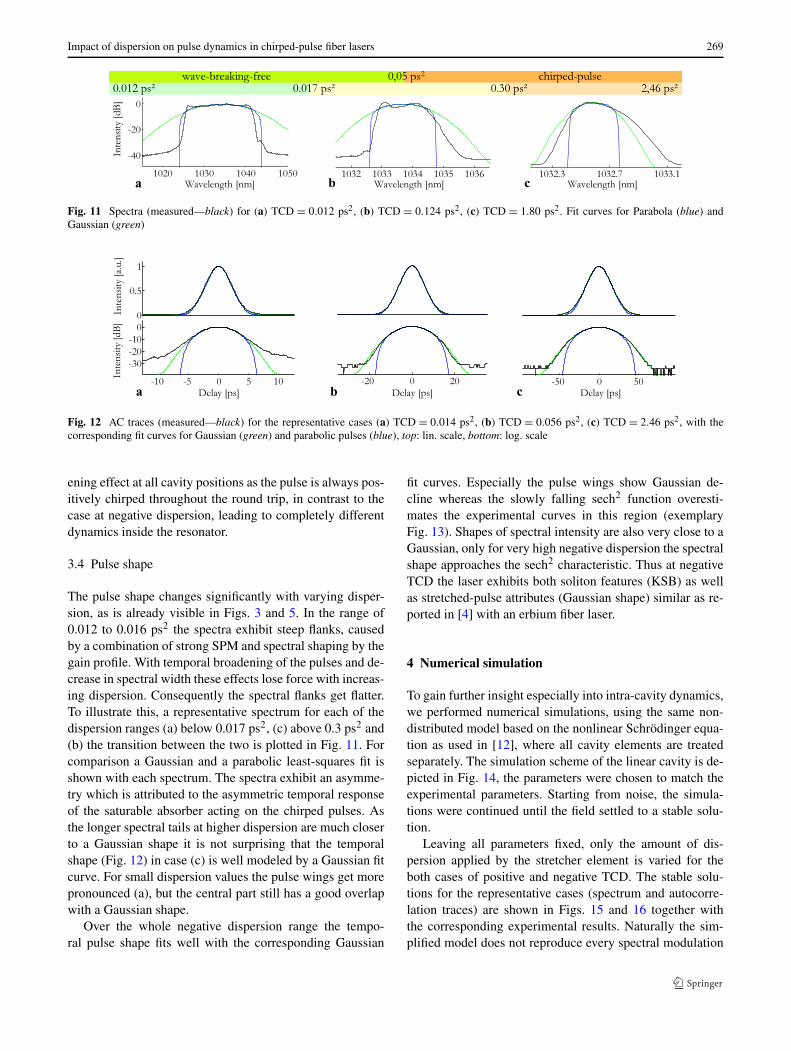
Fig. 11 Spectra (measured—black) for (a) TCD = 0.012 ps2, (b) TCD = 0.124 ps2, (c) TCD = 1.80 ps2. Fit curves for Parabola (blue) andGaussian (green)
Fig. 12 AC traces (measured—black) for the representative cases (a) TCD = 0.014 ps2, (b) TCD = 0.056 ps2, (c) TCD = 2.46 ps2, with thecorresponding fit curves for Gaussian (green) and parabolic pulses (blue), top: lin. scale, bottom: log. scale
ening effect at all cavity positions as the pulse is always pos-itively chirped throughout the round trip, in contrast to thecase at negative dispersion, leading to completely differentdynamics inside the resonator.
3.4 Pulse shape
The pulse shape changes significantly with varying disper-sion, as is already visible in Figs. 3 and 5. In the range of0.012 to 0.016 ps2 the spectra exhibit steep flanks, causedby a combination of strong SPM and spectral shaping by thegain profile. With temporal broadening of the pulses and de-crease in spectral width these effects lose force with increas-ing dispersion. Consequently the spectral flanks get flatter.To illustrate this, a representative spectrum for each of thedispersion ranges (a) below 0.017 ps2, (c) above 0.3 ps2 and(b) the transition between the two is plotted in Fig. 11. Forcomparison a Gaussian and a parabolic least-squares fit isshown with each spectrum. The spectra exhibit an asymme-try which is attributed to the asymmetric temporal responseof the saturable absorber acting on the chirped pulses. Asthe longer spectral tails at higher dispersion are much closerto a Gaussian shape it is not surprising that the temporalshape (Fig. 12) in case (c) is well modeled by a Gaussian fitcurve. For small dispersion values the pulse wings get morepronounced (a), but the central part still has a good overlapwith a Gaussian shape.
Over the whole negative dispersion range the tempo-ral pulse shape fits well with the corresponding Gaussian
fit curves. Especially the pulse wings show Gaussian de-cline whereas the slowly falling sech2 function overesti-mates the experimental curves in this region (exemplaryFig. 13). Shapes of spectral intensity are also very close to aGaussian, only for very high negative dispersion the spectralshape approaches the sech2 characteristic. Thus at negativeTCD the laser exhibits both soliton features (KSB) as wellas stretched-pulse attributes (Gaussian shape) similar as re-ported in [4] with an erbium fiber laser.
4 Numerical simulation
To gain further insight especially into intra-cavity dynamics,we performed numerical simulations, using the same non-distributed model based on the nonlinear Schrödinger equa-tion as used in [12], where all cavity elements are treatedseparately. The simulation scheme of the linear cavity is de-picted in Fig. 14, the parameters were chosen to match theexperimental parameters. Starting from noise, the simula-tions were continued until the field settled to a stable solu-tion.
Leaving all parameters fixed, only the amount of dis-persion applied by the stretcher element is varied for theboth cases of positive and negative TCD. The stable solu-tions for the representative cases (spectrum and autocorre-lation traces) are shown in Figs. 15 and 16 together withthe corresponding experimental results. Naturally the sim-plified model does not reproduce every spectral modulation
270 M. Baumgartl et al.
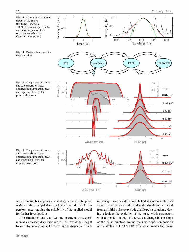
Fig. 13 AC (left) and spectrum(right) of the pulses(measured—black) at−0.21 ps2. For comparison thecorresponding curves for asech2 pulse (red) and aGaussian pulse (green)
Fig. 14 Cavity scheme used forthe simulations
Fig. 15 Comparison of spectraand autocorrelation tracesobtained from simulations (red)and experiment (gray) forpositive dispersion
Fig. 16 Comparison of spectraand autocorrelation tracesobtained from simulations (red)and experiment (gray) fornegative dispersion
or asymmetry, but in general a good agreement of the pulsewidth and the principal shape is obtained over the whole dis-persion range, proving the suitability of the applied modelfor further investigations.
The simulation easily allows one to extend the experi-mentally accessed dispersion range. This was done straightforward by increasing and decreasing the dispersion, start-
ing always from a random noise field distribution. Only veryclose to zero net-cavity dispersion the simulation is startedfrom an initial pulse to exclude double pulse solutions. Hav-ing a look at the evolution of the pulse width parameterswith dispersion in Fig. 17, reveals a change in the slopeof the pulse duration around the zero-dispersion-positionof the stretcher (TCD ≈ 0.05 ps2), which marks the transi-

Impact of dispersion on pulse dynamics in chirped-pulse fiber lasers 271
Fig. 17 Evolution of pulseparameters over TCD obtainedfrom numerical simulations,spectral width (blue) andchirped ac pulse duration(green) in log. scale, the areaaccessed experimentally ismarked gray
tion between the wave-breaking-free and the chirped-pulseregime (see also Fig. 19 for intra-cavity characteristics). Fur-thermore, one can see that the increase in pulse duration(decrease in spectral bandwidth) does not saturate at veryhigh dispersion values, but continues to grow. The maximumnonlinear phase shift accumulated during one round trip de-creases directly with increasing pulse duration, as pulse en-ergy is kept constant, indicating potential for pulse energyscaling.
4.1 Intracavity evolution
The lumped model used for the simulations allows to inves-tigate pulse dynamics inside the cavity. The evolution of thespectral and temporal pulse width and the chirp along thecavity is shown in Fig. 18 for different TCD values. For sim-plicity chirp is defined here as the negative amount of GDDrequired to compress the pulse to its minimum duration. Fig-ure 18(a–c) summarizes the characteristic cases for negativeTCD. The evolution of the chirp is qualitatively similar forthe whole negative dispersion region. Despite the stronglynegative TCD, in all three cases (Fig. 18(a–c)) the chirpchanges its sign in the first gain fiber section due to self-phase modulation. Consequently the pulse duration has twominima, while one minimum occurs inside the grating com-pressor, where the dominant temporal compression and sub-sequent stretching occurs. The effect of SPM on the spec-tral width clearly depends on the sign of the chirp. Thus thespectral width experiences a minimum during the first fiberpropagation, where the spectrum is initially slightly com-pressed and experiences significant nonlinear broadening inthe latter fiber section, as the chirp has changed from nega-tive to positive and the peak power is increased (Fig. 18(a–c)). The chirp is inversed again in the compressor and re-mains negative throughout the second fiber passage. Ac-cordingly the spectral width is decreased monotonically dur-ing the second pass and the pulses are negatively chirped atthe output as observed in the experiment. Interestingly thepoint where the chirp flips sign due to SPM can be shiftedby tailoring the nonlinearity, e.g. by changing the gain and
loss inside the cavity. This could be used to control the chirpof the output pulses without changing the position of theoutput coupler.
The evolution of the pulse duration changes significantlywith TCD. For highly negative GDD settings (Fig. 18(c)),the pulses are no longer shortened (Fig. 18(a, b)), butstretched by the “compressor”. The dispersive stretchingduring the first fiber passage and the temporal compressionas a consequence of the spectral narrowing during the sec-ond passage lose influence with increasing negative disper-sion. Finally at large negative TCD (c) the temporal dynamicis dominated by the compressor and the saturable absorberaction.
The scenario at positive TCD is illustrated in Fig. 18(d–f).At a total cavity dispersion below 0.05 ps2 (Fig. 18(d)) thematerial dispersion is partially compensated and the pulseduration features the for the wave-breaking-free regimecharacteristic minimum directly after the compressor. Thechirp is positive along the whole resonator and hence thepulse experiences monotonic dispersive broadening in thefiber sections. In the spectral domain the pulse is narrowedby the gain profile in the beginning of the fiber sections, butlater nonlinear broadening dominates at higher pulse energy.Finally the chirped pulse is both shortened in temporal andspectral domains by the saturable absorber.
Increasing the dispersion (Fig. 18(e, f)), the dispersioncontrol changes its sign and the temporal evolution becomesstrictly monotonic reaching the chirped-pulse regime. Dueto the longer pulses the spectrum experiences no significantbroadening and hence the gain bandwidth does no longershape the spectrum. In consequence also the spectral widthevolves monotonically. Clearly visible is the chirp decreas-ing effect of SPM on the highly positively chirped pulses. Atvery large TCD (Fig. 18(f)) the stretcher and the SA domi-nate the temporal evolution as the fiber dispersion becomesnegligible, accordingly the local temporal stretching featurecharacteristic for the chirped-pulse regime becomes prevail-ing. For maintaining a self-consistent evolution in the highlychirped pulse regime, the fiber nonlinearity strongly helpsto compensate the dispersive chirp, while obviously the SA

272 M. Baumgartl et al.
Fig. 18 Change in spectral width (blue) and pulse duration (green) along the cavity and evolution of chirp (black) for (a–c) negative and (d–f)positive TCD
plays the key role in the spectral and temporal domains as itrepresents the only pulse shortening mechanism in the cav-ity.
Note the different evolutions of the chirp for the casesin Fig. 18(d–f). In the WBF regime (Fig. 18(d)) the chirp is
ruled by the alternating dispersion and evolves linearly in thepositive fiber and negative compressor element, the SA haslittle influence. By contrast the behavior appears inversedin the highly chirped-pulse regime (Fig. 18(f)). Due to theinversed sign of the dispersion control the chirp is increas-

Impact of dispersion on pulse dynamics in chirped-pulse fiber lasers 273
Fig. 19 Pulse breathing ratioduring one resonator round tripover TCD, spectral (blue) andtemporal (green) domain
ing in the stretcher, whereas it is decreasing with increasingSPM in the fiber sections. The third case appears in the tran-sition area between the regimes (Fig. 18(e)), where the chirpis initially increasing in the fiber segments and is then par-tially compensated by SPM within the same fiber passage.
The pulse breathing inside the cavity is clearly largestclose to zero cavity dispersion as the pulses in this rangeare spectrally broad and thus susceptible to dispersion vari-ations and at the same time their short durations implystrong spectral breathing due to SPM. Indeed, as can beseen in Fig. 19, the breathing ratio decreases drasticallywith increasing TCD in the WBF regime. In the chirped-pulse regime, however, despite the in general relatively lowbreathing ratios, the intra-cavity pulse breathing increasesfirst of all with dispersion before it drops at extremely highTCD values.
4.2 Pulse energy scaling
In the above simulations a reduction in the accumulated non-linear phase per round trip of two orders of magnitude is ob-served with increasing TCD, which is what one would ex-pect from the increase in pulse duration. To investigate thebasic pulse energy scaling behavior within the chirped-pulseapproach, the simulation was started again with the same pa-rameters as before, but this time the saturation energy of thegain was varied. For each dispersion setting the simulationwas started from noise and every 1500 round trips the satu-ration energy was increased by 10 % until pulse breakup wasobserved. The saturation energies leading to pulse breakupare summarized in Fig. 20 for the different TCD values.The trend in Fig. 20 clearly visualizes the potential of thechirped-pulse approach for energy scaling. Stable pulse so-lutions beyond 100 nJ exist in our linear cavity design usingstandard fiber dimensions. However, a more complete pic-ture of the pulse energy limitations in chirped-pulse fiberlasers would require a detailed study of the influence of allimportant parameters in a more extensive set of simulations.The effect of an increased modulation depth [21] is of par-ticular interest for energy scaling in this regime. This issue
Fig. 20 Pulse energy scaling for the investigated cavity configuration:the pump power is increased stepwise, the graph shows the gain satu-ration energy for which pulse breakup is observed for each TCD
and also the influence of additional spectral filtering, differ-ent starting conditions and cavity configurations need fur-ther investigation.
5 Conclusion
A detailed study on the impact of different intra-cavity GDDvalues on the pulse dynamics in chirped-pulse fiber lasersis presented for the first time. Stable mode-locked opera-tion over a large total cavity dispersion range from −1.6to +2.5 ps2 is demonstrated in one oscillator setup, allow-ing for direct observation of the evolution of pulse parame-ters also across the different fiber laser regimes. Pulses ex-hibit average soliton features at negative TCD despite thesolely positive fiber dispersion in the cavity. Longer pulsesat larger dispersion values lower the peak power and thusallow to raise double pulsing threshold. Pulse durations in-crease quickly with higher dispersion especially at posi-tive net-cavity dispersion. Thus strongly chirped pulses withlong pulse durations (several tens of ps) and decreased band-widths due to decreased nonlinearities are obtained at largeTCD. Intra-cavity pulse evolution is discussed along withnumerical simulations, highlighting the characteristic dy-

274 M. Baumgartl et al.
namics in the different regimes with the strong local tempo-ral stretching feature in the chirped-pulse regime. The simu-lation furthermore confirms that the application of large pos-itive GDD values could be one approach for further energyscaling by restraining nonlinear effects due to the reducedpeak power.
Acknowledgements This work was partly supported by the GermanFederal Ministry of Education and Research (BMBF) under contract13N10773 as well as the Inter Carnot & Fraunhofer program underproject APUS. M. Baumgartl acknowledges support from Carl-Zeiss-Stiftung.
References
1. J.W. Nicholson, M. Andrejco, Opt. Express 14, 8160 (2006)2. B. Ortaç, M. Plötner, T. Schreiber, J. Limpert, A. Tünnermann
Opt. Express 15, 15595 (2007)3. I.N. Duling III, Opt. Lett. 16, 539 (1991)4. K. Tamura, L.E. Nelson, H.A. Haus, E.P. Ippen, Appl. Phys. Lett.
64, 149 (1994)5. H.A. Haus, K. Tamura, L.E. Nelson, E.P. Ippen, IEEE J. Quantum
Electron. 31, 591 (1995)6. L.E. Nelson, S.B. Fleischer, G. Lenz, E.P. Ippen, Opt. Lett. 21,
1759 (1996)
7. F.Ö. Ilday, J.R. Buckley, H. Lim, F.W. Wise, W.G. Clark, Opt.Lett. 28, 1365 (2003)
8. R. Herda, O.G. Okhotnikov, IEEE J. Quantum Electron. 40, 893(2004)
9. A. Chong, W.H. Renninger, F.W. Wise, J. Opt. Soc. Am. B 25, 140(2008)
10. L.M. Zhao, D.Y. Tang, J. Wu, Opt. Lett. 31, 1788 (2006)11. A. Chong, W. Renninger, F. Wise, Opt. Lett. 32, 2408 (2007)12. M. Baumgartl, B. Ortaç, C. Lecaplain, A. Hideur, J. Limpert, A.
Tünnermann, Opt. Lett. 35, 2311 (2010)13. B. Ortaç, M. Baumgartl, J. Limpert, A. Tünnermann, Opt. Lett.
34, 1585 (2009)14. C. Lecaplain, B. Ortaç, G. Machinet, J. Boullet, M. Baumgartl, T.
Schreiber, E. Cormier, A. Hideur, Opt. Lett. 35, 3156 (2010)15. M. Baumgartl, F. Jansen, F. Stutzki, C. Jauregui, B. Ortaç, J.
Limpert, A. Tünnermann, Opt. Lett. 36, 244 (2011)16. W.H. Renninger, A. Chong, F.W. Wise, Opt. Lett. 33, 3025 (2008)17. D.-F. Liu, X.-J. Zhu, C.-H. Wang, J.-J. Yu, E.-X. Fang, J.-J. Wang,
Laser Phys. 21, 414 (2011)18. B. Ortaç, M. Plötner, J. Limpert, A. Tünnermann, Opt. Express
15, 16794 (2007)19. S.M.J. Kelly, Electron. Lett. 28, 806 (1992)20. M.L. Dennis, I.N. Duling III, IEEE J. Quantum Electron. 30, 1469
(1994)21. C. Lecaplain, M. Baumgartl, T. Schreiber, A. Hideur, Opt. Express
19, 26742 (2011)