im3 p6/p6 led piezo ultrasonic scaler
TRANSCRIPT

iM3 P6/P6 LED Piezo Ultrasonic Scaler
Directions for Use
Manufactured for and distributed by:
iM3 Pty Ltd, 21 Chaplin Drive, Lane Cove NSW 2066, Australia
iM3 Dental Ltd
IRELAND
Tel: +353 (0) 1 6911277
iM3 Pty Ltd
Sydney, AUSTRALIA
Tel: +612 9420 5766
iM3 Inc
Vancouver, WA USA
Tel: (800) 664-6348
www.im3vet.com
made in Taiwan
- 1 -
Bonart Co., Ltd. owns all rights to this publication. This publication shall be used solely as a
reference for operation, maintenance, and repair of Bonart equipment. No part of this
document may be reproduced or distributed in any form for any other purpose.
In the event of inadvertent or deliberate publication, Bonart intends to enforce its rights to
this manual under the copyright law. Reproduction of the materials presented in this manual
without the express written permission of Bonart is prohibited.
The contents of this manual are subject to change without prior notice.
PROPERTY OF BONART CO., LTD.
ALL RIGHTS RESERVED
Document No. RD-02-24-04 Rev.1.1 (10/2020)
Printed in Taiwan, R.O.C.

- 2 -
Operator Safety
PLEASE READ THIS MANUAL BEFORE OPERATING. THE iM3 P6
PIEZOELECTRIC ULTRASONIC SCALER SHOULD BE OPERATED, MAINTAINED
AND REPAIRED BY QUALFIED AND TRAINED PERSONNEL ONLY.
NOTE, CAUTION AND WARNING STATEMENTS
NOTE: Provides tips and advice.
CAUTION: Provides correct operating or maintenance procedures
WARNING: Alerts user of danger of injury or damage.
About the iM3 P6 Piezoelectric Ultrasonic Scaler
How it works
The iM3 P6 Piezoelectric Ultrasonic Scaler generates ultrasonic waves in the hand piece to
vibrate the tip, which allows the iM3 P6 to remove calculus and tartar easily. These
ultrasonic waves are created by 4 ceramic piezoelectric plates subjected to high frequency
alternating currents.
The piezoelectric transducer operates at a frequency of 29khz with minimal noise and heat,
and efficiently reduces the amount of cooling water required during treatment. This
electric-mechanical feature provides greater efficiency than traditional magnetostrictive
systems.
- 3 -
Table of Contents
Copyrights ……………………………... 1
Operator Safety ..........………………………. 2
Contents ..……………………………. 3
Section I. Indications for use ..……………………………. 4
Section II. Contraindications and Warnings …………………….. 4
Section III. Precautions .…………………………….. 4
Section IV. Infection Control ……………………………... 6
Section V. Installation …..………………………….. 8
Section VI. General Descriptions and Information of Parts ……………. 12
Section VII. Techniques ………………………………. 13
Section VIII. System Maintenance …………………………..… 15
Section IX. Electromagnetic Compatibility …………………………... 15
Section X. Troubleshooting ………………………………. 18
Section XI. Symbols ………………………………. 20
Section XII. Specifications ………………………………. 20
Section XIII. Disposal ..…………………………….. 21
- 4 -
Section I: Indications for Use
Ultrasonic procedures:
Removal of calculus and plaque during dental prophylaxis.
General supra and sub-gingival scaling applications.
Periodontal debridement for all types of periodontal diseases.
Endodontic procedures.
Section II: Contraindications and Warnings
Do not use the iM3 P6 for restorative dental procedures.
Do not use the iM3 P6 if the patient or operator is wearing a pacemaker.
Do not immerse the iM3 P6 in water or liquid. If the iM3 P6 has water damage, return
the machine to iM3 for servicing.
Do not modify the iM3 P6. Modifications will invalidate the warranty on the machine
and may endanger the patient and operator.
Do not attempt service or maintenance while the iM3 P6 is in use.
Section III: Precautions
3-A: Precautions for all Ultrasonic Scaler Units and Systems
Ensure sufficient water flow to the scaler tip during use to cool the hand piece and tips.
Take precaution as all ultrasonic scalers produce aerosols that may transmit
contagious diseases.
Use tips manufactured by iM3 for optimal performance and results.
Keep the unit away from intense heat. Excessive heat may damage the electronic
components.
Switch the water valve off when the iM3 P6 is not in use.
Do not treat patients who have a pacemaker.
- 5 -
3-B: Precautions for Ultrasonic Prophylaxis Procedures
Scaler tips (piezo tips) will wear with use. Tips with 2mm of wear will lose
approximately 50% of their scaling efficiency. In general, it is recommended that tips
be discarded and replaced every 4-6 months to maintain optimal efficiency and avoid
breakage.
Avoid direct contact of tips with the patient’s lips, cheeks and tongue.
Do not reuse scaling tips (piezo tips) that are damaged, bent, or reshaped. Discard
immediately.
Use the long axis of the scaler tip (piezo tip) to wipe accretions from the tooth. Do not
gouge the tooth with the tip.
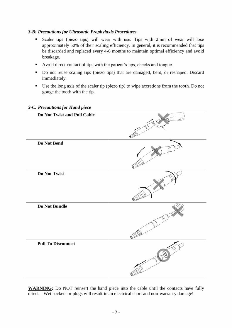
3-C: Precautions for Hand piece
Do Not Twist and Pull Cable
Do Not Bend
Do Not Twist
Do Not Bundle
Pull To Disconnect
WARNING: Do NOT reinsert the hand piece into the cable until the contacts have fully
dried. Wet sockets or plugs will result in an electrical short and non-warranty damage!
- 6 -
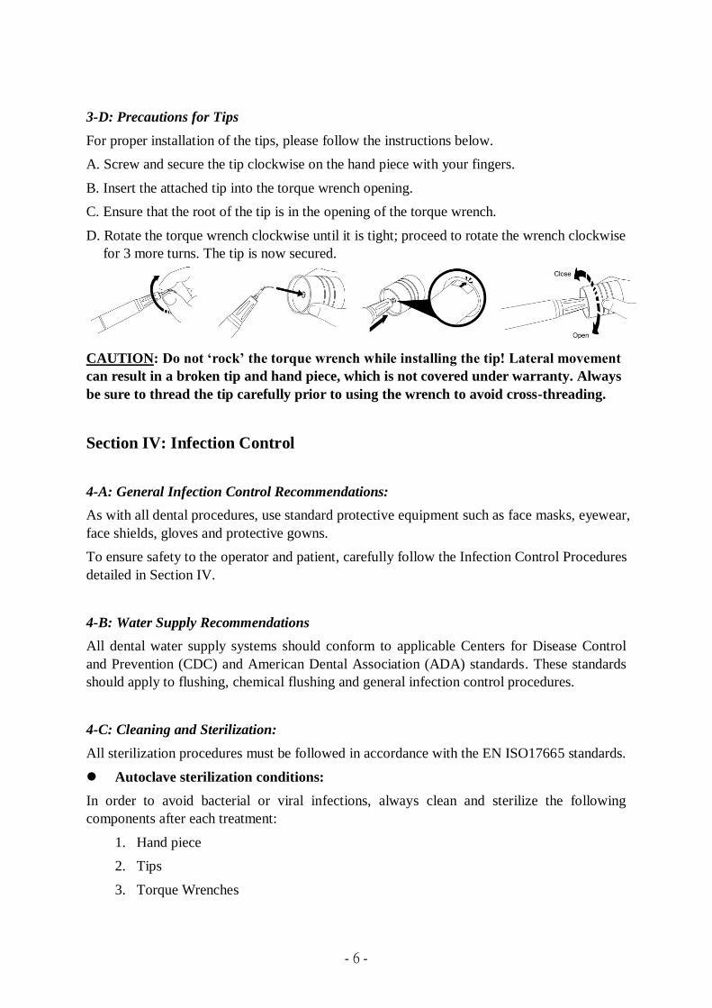
3-D: Precautions for Tips
For proper installation of the tips, please follow the instructions below.
A. Screw and secure the tip clockwise on the hand piece with your fingers.
B. Insert the attached tip into the torque wrench opening.
C. Ensure that the root of the tip is in the opening of the torque wrench.
D. Rotate the torque wrench clockwise until it is tight; proceed to rotate the wrench clockwise
for 3 more turns. The tip is now secured.
CAUTION: Do not ‘rock’ the torque wrench while installing the tip! Lateral movement
can result in a broken tip and hand piece, which is not covered under warranty. Always
be sure to thread the tip carefully prior to using the wrench to avoid cross-threading.
Section IV: Infection Control
4-A: General Infection Control Recommendations:
As with all dental procedures, use standard protective equipment such as face masks, eyewear,
face shields, gloves and protective gowns.
To ensure safety to the operator and patient, carefully follow the Infection Control Procedures
detailed in Section IV.
4-B: Water Supply Recommendations
All dental water supply systems should conform to applicable Centers for Disease Control
and Prevention (CDC) and American Dental Association (ADA) standards. These standards
should apply to flushing, chemical flushing and general infection control procedures.
4-C: Cleaning and Sterilization:
All sterilization procedures must be followed in accordance with the EN ISO17665 standards.
Autoclave sterilization conditions:
In order to avoid bacterial or viral infections, always clean and sterilize the following
components after each treatment:
1. Hand piece
2. Tips
3. Torque Wrenches
- 7 -
The components above are composed of materials that can withstand a maximum temperature
of 135℃ or (275℉) for 3 minutes. Items should take at least 16 minutes to dry before using
it.
WARNING: The components should be steam autoclaved for sterilization. Do not use
any other method of sterilization (dry heat, radiation, ethylene oxide, gas, low-
temperature plasma, etc.)
CAUTION: Prior to cleaning and sterilizing your iM3 P6 unit, always remember to
turn off the device by using the power switch and disconnect the power plug from the
outlet.
CAUTION: Please make sure that the components are completely dry before starting
the sterilization cycle. This will prevent stains and patches from appearing on the
surface of the accessories.
NOTE: The Sterilization Assurance Level (SAL) of steam autoclave should be 10-6. (The
sterilization must be performed in compliance to the standard EN/ISO 17665 or
ANSI/AAMI ST79)
NOTE: Please refer to the manufacturer’s guidelines of the disinfectant solution
/detergent in question to determine if is appropriate for disinfecting instruments and/or
for use in ultrasonic cleaning applications.
WARNING: Do not use any other method of sterilization (dry heat, radiation, ethylene
oxide, gas, low-temperature plasma, etc.)
Preparations for sterilization
1. Carefully remove the tip from the hand piece using the torque wrench.
2. Clean and disinfect the surface of the outer casing, cords and connectors with a cloth and
mild detergent or disinfectant solution with a neutral pH (pH7).
3. Allow the disinfectant solution to air dry.
Preparations for autoclave sterilization of the hand piece
1. Take special care not to break the threading pin of the hand piece. The threading pin is
where the tips are installed.
NOTE: Breakage of this treading pin is not covered under warranty.
2. Disinfect the hand piece with a cloth and mild disinfectant containing a neutral pH.
3. Dry the electric contacts by blowing air onto them with the syringe.
WARNING: Do NOT reinsert the hand piece into the cable until the contacts have fully
dried!
- 8 -
4. Seal the hand piece in a sterilization pouch (without any tips).
5. Follow the instructions of your autoclave machine to sterilize the hand piece in the
autoclave machine. The components are composed of materials that can withstand a
maximum temperature of 135℃ or (275℉) for 3 minutes. Items should take
approximately at least 16 minutes to dry.
Preparations for Autoclave sterilization of the tip(s)
1. Clean the tip(s) preferably in an ultrasonic tank with mild disinfectant containing a
neutral pH.
2. Rinse the tip(s) in distilled water.
3. Dry the tip(s).
NOTE: Before starting the sterilization cycle, make sure that the inside of the tip is
completely dry by blowing air through the internal hole with the syringe. This will
prevent stains and patches from appearing on the surface of the tip.
4. Seal the tip inside a sterilization pouch. If you are autoclaving more than 1 tip, place each
tip in an individual bag.
5. Autoclave the tip.
Preparations for Autoclave sterilization of the torque wrench
1. Clean the wrench.
2. Disinfect the wrench with a cloth and mild disinfectant containing a neutral pH.
3. Seal the wrench in a sterilization pouch.
4. Autoclave the wrench.
Section V: Installation
5-A: General Information
If the installation of your iM3 P6 system is performed by non-iM3 distributor personnel,
check to see that requirements below are followed.
5-B: Water Line Requirements
Incoming water supply line pressure to the iM3 P6 must be 25 psi (172 kPa minimum) to
60 psi (414Kpa maximum). If your dental water supply line pressure is above 60 psi,
install a water regulator on the water supply line to your iM3 P6 unit.
After the above installation requirement is fulfilled, thoroughly flush the water prior to
connecting to the scaler.
- 9 -
Please use the manual shut-off valve on the dental water system supply line when the
office will be unoccupied.
5-C: Electrical Requirements
Refer to Section XII: Specifications
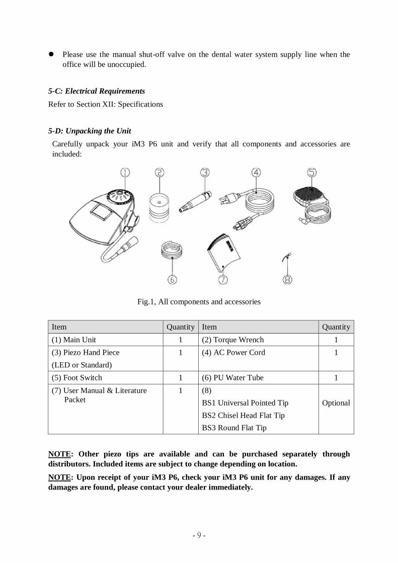
5-D: Unpacking the Unit
Carefully unpack your iM3 P6 unit and verify that all components and accessories are
included:
Fig.1, All components and accessories
Item Quantity Item Quantity
(1) Main Unit 1 (2) Torque Wrench 1
(3) Piezo Hand Piece
(LED or Standard)
1 (4) AC Power Cord 1
(5) Foot Switch 1 (6) PU Water Tube 1
(7) User Manual & Literature
Packet
1 (8)
BS1 Universal Pointed Tip
BS2 Chisel Head Flat Tip
BS3 Round Flat Tip
Optional
NOTE: Other piezo tips are available and can be purchased separately through
distributors. Included items are subject to change depending on location.
NOTE: Upon receipt of your iM3 P6, check your iM3 P6 unit for any damages. If any
damages are found, please contact your dealer immediately.
- 10 -
5-E: Power Cord / Power Connection
Always make sure that the power switch is set to the OFF position before performing the
following tasks:
Plug the detachable AC cord into the back of the unit.
Plug the 3-prong plug into a grounded outlet.
Safety Instructions
A. Grounding:
Prior to connecting accessories to the unit, check that the main unit is plugged into a
grounded wall outlet.
B. Main voltage range and fuse:
Prior to plugging the AC adapter into the power outlet, check that the voltage is supported.
5-F: Foot Control Cable Assembly Connection
Align the pins of the foot control plug with the receptacle on the back of the device and push
in until the plug is firmly seated.
5-G: Water Supply Line Connection
Push the blue water tube into the stainless steel receptacle until the water tube cannot be
pushed any further. Then tighten the screw.
Connect the quick connect to the water supply line. The iM3 P6 should be prepackaged with
a male quick connect. If a female quick connect is necessary, please contact the iM3
representative to purchase the part.
Inspect all connections for leaks.
To remove the water line from the iM3 P6 scaler, first turn off the water supply or disconnect
the water supply line. Then loosen nut on the water tube from the receptacle of the unit and
gently pull the water tube out.
5-H: Hand piece connection and tip compatibility
The iM3 P6 hand piece is not only compatible with iM3’s tips, but also with tips designed for
Satelec Acteon piezoelectric scalers. The hand piece is also detachable from the hand piece
cable. During use, the operating frequency of the tip is measured to be approximately 29khz.
- 11 -
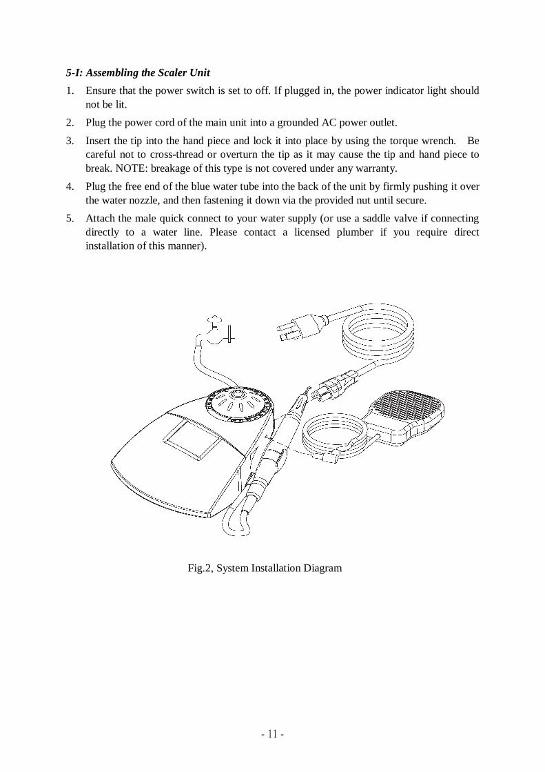
5-I: Assembling the Scaler Unit
1. Ensure that the power switch is set to off. If plugged in, the power indicator light should
not be lit.
2. Plug the power cord of the main unit into a grounded AC power outlet.
3. Insert the tip into the hand piece and lock it into place by using the torque wrench. Be
careful not to cross-thread or overturn the tip as it may cause the tip and hand piece to
break. NOTE: breakage of this type is not covered under any warranty.
4. Plug the free end of the blue water tube into the back of the unit by firmly pushing it over
the water nozzle, and then fastening it down via the provided nut until secure.
5. Attach the male quick connect to your water supply (or use a saddle valve if connecting
directly to a water line. Please contact a licensed plumber if you require direct
installation of this manner).
Fig.2, System Installation Diagram

- 12 -
Section VI: General Information and Parts Description
Fig.3, Outlook diagram
1. Main Unit
The main unit generates power and produces a signal that is passed to the hand piece.
The hand piece is then powered up and vibrates the installed tip.
2. Hand piece (LED* or Standard)
*LED version not available in some regions. Please check dealers for availability.
3. Footswitch
4. Power Cord
5. Water-In Nozzle
6. Power Panel
The power panel displays power levels from 1 to 20. The selected power level will
be indicated by a lit number.
7. Main Power Switch
8. Water-Adjustment Knob
9. Power-Adjustment Dial
- 13 -
Section VII: Techniques
7-A: Performing Ultrasonic Scaling Procedures
1. Use purified or distilled water to prevent infection when patients experience tissue
laceration during treatment.
2. Keep the power cord tidy to avoid tripping and other accidents.
3. Position the footswitch in an easily-accessible spot for the user. Keep the footswitch cord
tidy to avoid tripping and other accidents.
4. Lock the tip in the hand piece securely using the enclosed torque wrench.
CAUTION: DO NOT FORCE OR OVERTURN THE TIP INTO PLACE! Doing so will
damage the tip, hand piece, and wrench.
NOTE: The scaler will not operate if the tip is either removed from the hand piece or
improperly installed.
5. Hold the hand piece over a sink or drain with a tip installed. Verify that water is reaching
the tip.
6. Check your iM3 piezo tip for wear and replace as needed. Tips should be disposed of and
replaced every 4-6 months.
7. Use the foot control to regulate water flow to the hand piece. Hold down the foot control to
allow water to flow through. Release the foot control to stop.
8. Adjust the water flow to the desired level using the water-adjustment knob. Increase the
water flow by turning the water-adjust knob clockwise. Decrease the water flow by
turning the water-adjustment knob counter-clockwise.
NOTE: Increased water flow results in a cooler hand piece temperature.
CAUTION: During operation, a continuous flow of water is required to keep the hand
piece cool.
9. The LED in the hand piece lights up when the foot switch is activated. It will remain lit for
20 seconds after the foot switch is released (on LED model hand pieces only).
7-B: Patient Comfort Considerations
1. Position the patient comfortably in the patient chair. Adjust the chair angle and position to
access the patient's oral cavity with ease and comfort.
2. Remove excess saliva and debris in the patient’s mouth with a saliva ejector.
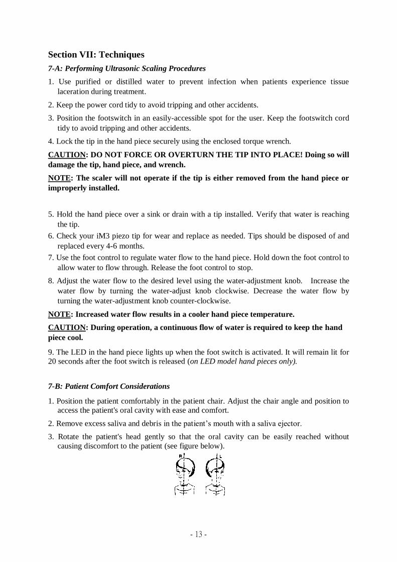
3. Rotate the patient's head gently so that the oral cavity can be easily reached without
causing discomfort to the patient (see figure below).
- 14 -
4. During treatment, try to keep the angle between the surface of the tooth and scaling
insert at 15 degrees. If the patient experiences any discomfort during treatment, follow
the suggestions below:
Increase your manual movement speed of the hand piece on the surface when treating
sensitive areas.
Treat less sensitive areas first, and then return to sensitive areas.
If the problem persists, reduce the power output intensity of the hand piece.
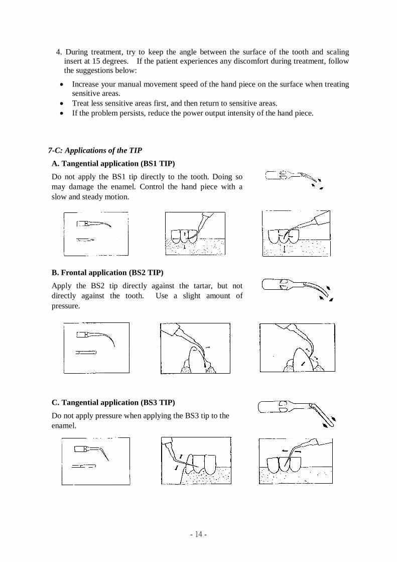
7-C: Applications of the TIP
A. Tangential application (BS1 TIP)
Do not apply the BS1 tip directly to the tooth. Doing so
may damage the enamel. Control the hand piece with a
slow and steady motion.
B. Frontal application (BS2 TIP)
Apply the BS2 tip directly against the tartar, but not
directly against the tooth. Use a slight amount of
pressure.
C. Tangential application (BS3 TIP)
Do not apply pressure when applying the BS3 tip to the
enamel.
- 15 -
Section VIII: System Maintenance
8-A. Hand piece maintenance
1. After each use, the hand piece and tip should be rinsed with clean water for about 20
to 30 seconds.
2. Inspect the hand piece cable daily to ensure it is in good condition.
3. For sterilization of the hand piece, please refer to Section IV.
8-B. TIP maintenance
Worn out tips can adversely affect performance, resulting in insufficient power and
vibration. Check tips regularly for wear and tear and replace as necessary. Tips should
be disposed of and replaced every 4-6 months.
8-C. Main Unit Maintenance
The housing of the iM3 P6, as well as the hand piece cord, should be cleaned and
disinfected (using alcohol or soap and warm water) on a daily basis.
Section IX: Electromagnetic Compatibility
The use of accessories or replacement parts other than those specified or sold by iM3 may
have the consequence of increasing the electromagnetic emissions or decreasing the immunity
of the device.
The device must not be used near other equipment or placed on top of it. If this cannot be
avoided, correct operation of the device in operating conditions must be checked prior to use.
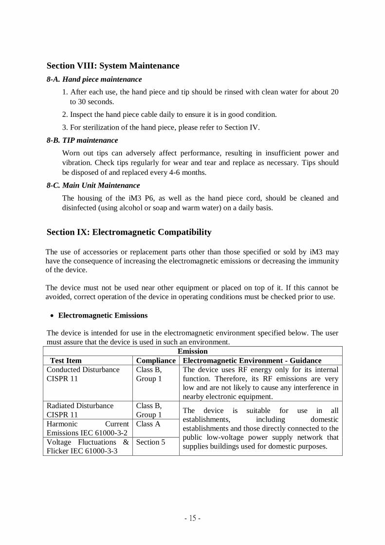
Electromagnetic Emissions
The device is intended for use in the electromagnetic environment specified below. The user
must assure that the device is used in such an environment.
Emission
Test Item
Compliance Electromagnetic Environment - Guidance
Conducted Disturbance
CISPR 11
Class B,
Group 1
The device uses RF energy only for its internal
function. Therefore, its RF emissions are very
low and are not likely to cause any interference in
nearby electronic equipment.
Radiated Disturbance
CISPR 11
Class B,
Group 1 The device is suitable for use in all
establishments, including domestic
establishments and those directly connected to the
public low-voltage power supply network that
supplies buildings used for domestic purposes.
Harmonic Current
Emissions IEC 61000-3-2
Class A
Voltage Fluctuations &
Flicker IEC 61000-3-3
Section 5
- 16 -
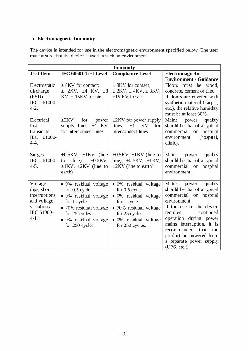
Electromagnetic Immunity
The device is intended for use in the electromagnetic environment specified below. The user
must assure that the device is used in such an environment.
Immunity
Test Item IEC 60601 Test Level Compliance Level Electromagnetic
Environment - Guidance
Electrostatic
discharge
(ESD)
IEC 61000-
4-2.
± 8KV for contact;
± 2KV, ±4 KV, ±8
KV, ± 15KV for air
± 8KV for contact;
± 2KV, ± 4KV, ± 8KV,
±15 KV for air
Floors must be wood,
concrete, cement or tiled.
If floors are covered with
synthetic material (carpet,
etc.), the relative humidity
must be at least 30%.
Electrical
fast
transients
IEC 61000-
4-4.
±2KV for power
supply lines; ±1 KV
for interconnect lines
±2KV for power supply
lines; ±1 KV for
interconnect lines
Mains power quality
should be that of a typical
commercial or hospital
environment (hospital,
clinic).
Surges
IEC 61000-
4-5.
±0.5KV, ±1KV (line
to line); ±0.5KV,
±1KV, ±2KV (line to
earth)
±0.5KV, ±1KV (line to
line); ±0.5KV, ±1KV,
±2KV (line to earth)
Mains power quality
should be that of a typical
commercial or hospital
environment.
Voltage
dips, short
interruptions
and voltage
variations
IEC 61000-
4-11.
0% residual voltage
for 0.5 cycle.
0% residual voltage
for 1 cycle.
70% residual voltage
for 25 cycles.
0% residual voltage
for 250 cycles.
0% residual voltage
for 0.5 cycle.
0% residual voltage
for 1 cycle.
70% residual voltage
for 25 cycles.
0% residual voltage
for 250 cycles.
Mains power quality
should be that of a typical
commercial or hospital
environment.
If the use of the device
requires continued
operation during power
mains interruption, it is
recommended that the
product be powered from
a separate power supply
(UPS, etc.).
- 17 -
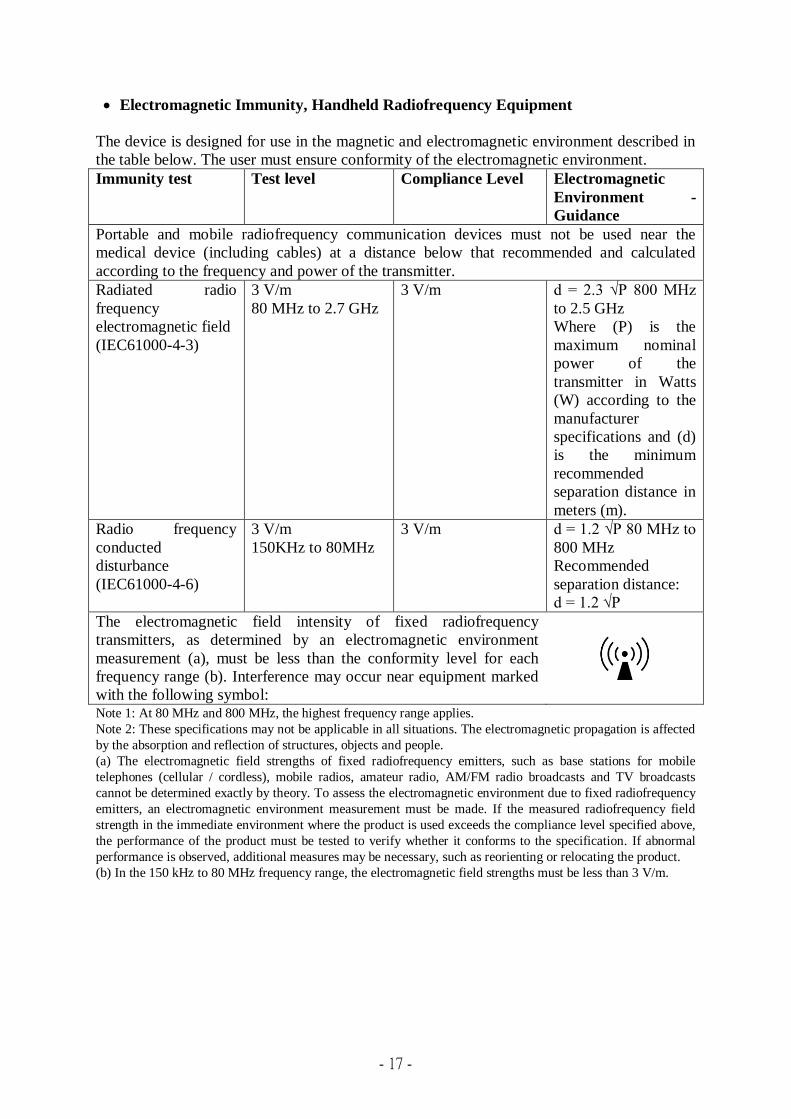
Electromagnetic Immunity, Handheld Radiofrequency Equipment
The device is designed for use in the magnetic and electromagnetic environment described in
the table below. The user must ensure conformity of the electromagnetic environment.
Immunity test Test level Compliance Level Electromagnetic
Environment -
Guidance
Portable and mobile radiofrequency communication devices must not be used near the
medical device (including cables) at a distance below that recommended and calculated
according to the frequency and power of the transmitter.
Radiated radio
frequency
electromagnetic field
(IEC61000-4-3)
3 V/m
80 MHz to 2.7 GHz
3 V/m d = 2.3 √P 800 MHz
to 2.5 GHz
Where (P) is the
maximum nominal
power of the
transmitter in Watts
(W) according to the
manufacturer
specifications and (d)
is the minimum
recommended
separation distance in
meters (m).
Radio frequency
conducted
disturbance
(IEC61000-4-6)
3 V/m
150KHz to 80MHz
3 V/m d = 1.2 √P 80 MHz to
800 MHz
Recommended
separation distance:
d = 1.2 √P
The electromagnetic field intensity of fixed radiofrequency
transmitters, as determined by an electromagnetic environment
measurement (a), must be less than the conformity level for each
frequency range (b). Interference may occur near equipment marked
with the following symbol:
Note 1: At 80 MHz and 800 MHz, the highest frequency range applies.
Note 2: These specifications may not be applicable in all situations. The electromagnetic propagation is affected
by the absorption and reflection of structures, objects and people.
(a) The electromagnetic field strengths of fixed radiofrequency emitters, such as base stations for mobile
telephones (cellular / cordless), mobile radios, amateur radio, AM/FM radio broadcasts and TV broadcasts
cannot be determined exactly by theory. To assess the electromagnetic environment due to fixed radiofrequency
emitters, an electromagnetic environment measurement must be made. If the measured radiofrequency field
strength in the immediate environment where the product is used exceeds the compliance level specified above,
the performance of the product must be tested to verify whether it conforms to the specification. If abnormal
performance is observed, additional measures may be necessary, such as reorienting or relocating the product.
(b) In the 150 kHz to 80 MHz frequency range, the electromagnetic field strengths must be less than 3 V/m.
- 18 -
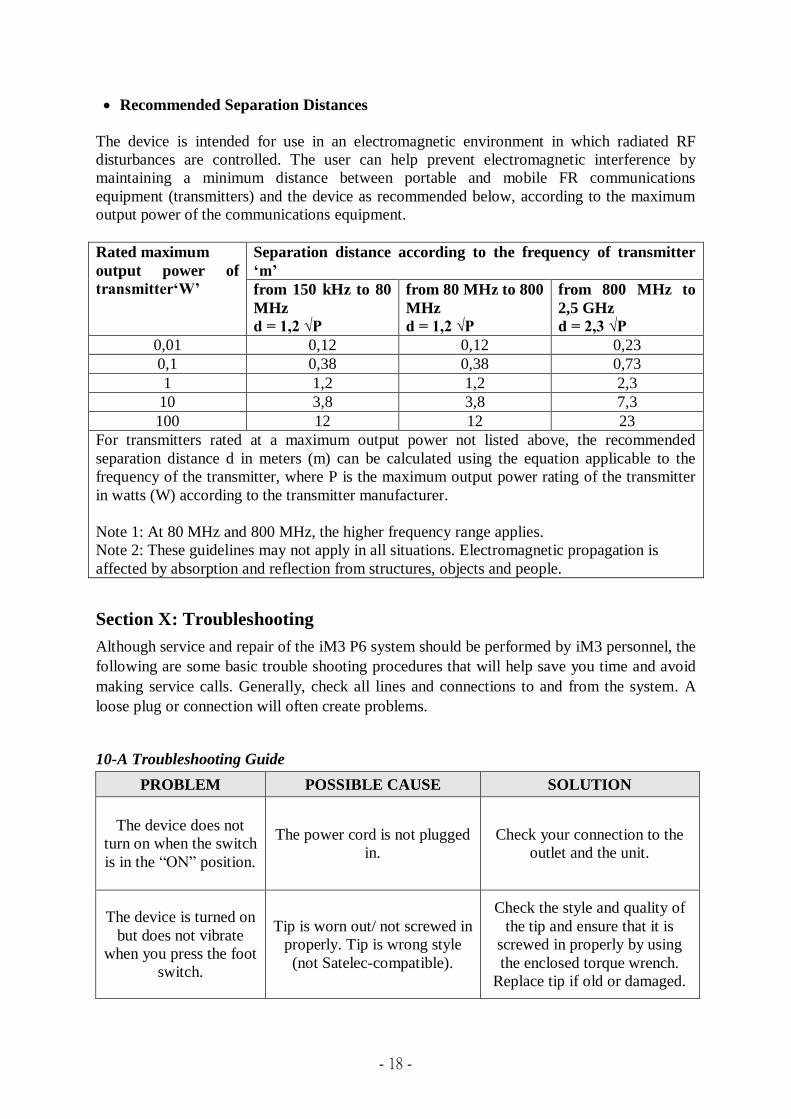
Recommended Separation Distances
The device is intended for use in an electromagnetic environment in which radiated RF
disturbances are controlled. The user can help prevent electromagnetic interference by
maintaining a minimum distance between portable and mobile FR communications
equipment (transmitters) and the device as recommended below, according to the maximum
output power of the communications equipment.
Rated maximum
output power of
transmitter‘W’
Separation distance according to the frequency of transmitter
‘m’
from 150 kHz to 80
MHz
d = 1,2 √P
from 80 MHz to 800
MHz
d = 1,2 √P
from 800 MHz to
2,5 GHz
d = 2,3 √P
0,01 0,12 0,12 0,23
0,1 0,38 0,38 0,73
1 1,2 1,2 2,3
10 3,8 3,8 7,3
100 12 12 23
For transmitters rated at a maximum output power not listed above, the recommended
separation distance d in meters (m) can be calculated using the equation applicable to the
frequency of the transmitter, where P is the maximum output power rating of the transmitter
in watts (W) according to the transmitter manufacturer.
Note 1: At 80 MHz and 800 MHz, the higher frequency range applies.
Note 2: These guidelines may not apply in all situations. Electromagnetic propagation is
affected by absorption and reflection from structures, objects and people.
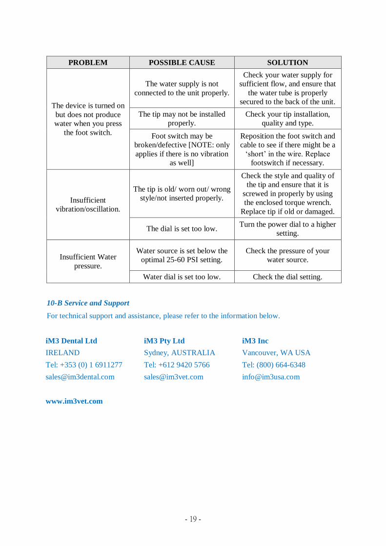
Section X: Troubleshooting
Although service and repair of the iM3 P6 system should be performed by iM3 personnel, the
following are some basic trouble shooting procedures that will help save you time and avoid
making service calls. Generally, check all lines and connections to and from the system. A
loose plug or connection will often create problems.
10-A Troubleshooting Guide
PROBLEM POSSIBLE CAUSE SOLUTION
The device does not
turn on when the switch
is in the “ON” position.
The power cord is not plugged
in.
Check your connection to the
outlet and the unit.
The device is turned on
but does not vibrate
when you press the foot
switch.
Tip is worn out/ not screwed in
properly. Tip is wrong style
(not Satelec-compatible).
Check the style and quality of
the tip and ensure that it is
screwed in properly by using
the enclosed torque wrench.
Replace tip if old or damaged.
- 19 -
PROBLEM POSSIBLE CAUSE SOLUTION
The device is turned on
but does not produce
water when you press
the foot switch.
The water supply is not
connected to the unit properly.
Check your water supply for
sufficient flow, and ensure that
the water tube is properly
secured to the back of the unit.
The tip may not be installed
properly.
Check your tip installation,
quality and type.
Foot switch may be
broken/defective [NOTE: only
applies if there is no vibration
as well]
Reposition the foot switch and
cable to see if there might be a
‘short’ in the wire. Replace
footswitch if necessary.
Insufficient
vibration/oscillation.
The tip is old/ worn out/ wrong
style/not inserted properly.
Check the style and quality of
the tip and ensure that it is
screwed in properly by using
the enclosed torque wrench.
Replace tip if old or damaged.
The dial is set too low. Turn the power dial to a higher
setting.
Insufficient Water
pressure.
Water source is set below the
optimal 25-60 PSI setting.
Check the pressure of your
water source.
Water dial is set too low. Check the dial setting.
10-B Service and Support
For technical support and assistance, please refer to the information below.
iM3 Dental Ltd
IRELAND
Tel: +353 (0) 1 6911277
iM3 Pty Ltd
Sydney, AUSTRALIA
Tel: +612 9420 5766
iM3 Inc
Vancouver, WA USA
Tel: (800) 664-6348
www.im3vet.com
- 20 -
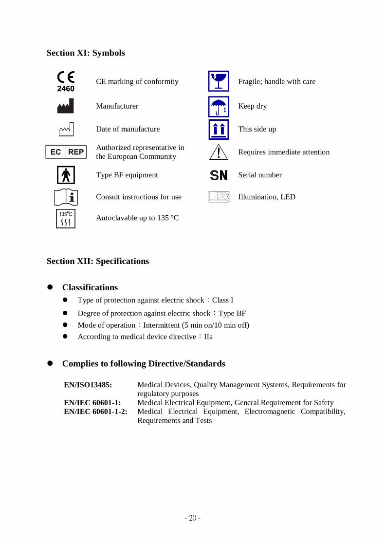
Section XI: Symbols
CE marking of conformity
Fragile; handle with care
Manufacturer
Keep dry
Date of manufacture
This side up
Authorized representative in
the European Community Requires immediate attention
Type BF equipment
Serial number
Consult instructions for use
Illumination, LED
Autoclavable up to 135 °C
Section XII: Specifications
Classifications
Type of protection against electric shock:Class I
Degree of protection against electric shock:Type BF
Mode of operation:Intermittent (5 min on/10 min off)
According to medical device directive:IIa
Complies to following Directive/Standards
EN/ISO13485: Medical Devices, Quality Management Systems, Requirements for
regulatory purposes
EN/IEC 60601-1: Medical Electrical Equipment, General Requirement for Safety
EN/IEC 60601-1-2: Medical Electrical Equipment, Electromagnetic Compatibility,
Requirements and Tests

- 21 -
Specifications
Power supply 115V ±5% ~50/60Hz 28VA
230V ±5% ~50/60Hz 28VA
Working frequency 26KHz ~ 32KHz
Water supply 25~60 PSIG (172~414KPa)
Dimension 19.5 cm(L) x 16 cm(W) x 8.5 cm(H)
Weight 1.3 Kg
Hand piece Cable
Light color(LED)
Luminous Intensity
260 cm
White LED
Min. 30,000 lux
Footswitch Cable 250 cm
Operation environment
Temperature
10℃~40℃
Relative Humidity 15% ~ 85%
Atmospheric pressure 860~1060 hPa
Transport and storage conditions
Temperature
10℃~60℃
Relative Humidity 15% ~ 85%
Section XIII: Disposal
Please follow county and state regulations for disposal of the iM3 P6.

- 22 -
Bonart Co., Ltd.
No.80, Wuxun St., Anle Dist.,
Keelung City, 20446, Taiwan, R.O.C.
Tel: 886-2-22983980
Fax:886-2-22983981
Email:[email protected]
2460
COPYRIGHT© BONART CO., LTD.