ilc e-driven e source - agenda.linearcollider.org
TRANSCRIPT

ILC E-driven e+ Source
T. Omori (KEK)AWLC2020, October 2020, fully virtual on Zoom 1

• E-driven positron source is independent from entire system, thus it has big advantages in commissioning and availability.
• Early commissioning and availability are essential for success of the project.
• The realistic design exist which meets ILC requirements. • It has factor two margin in target destruction limit (70 J/g).• Instantaneous thermal load to the target is similar to that of SLC.
The number of hits per year per spot is about 1/10 of that of the SLC target.
• The design of the ILC positron source based on commercially available components and available products from collaborative institutes has been established.
• Preparation of the E-driven source is in good condition.
Introduction
Nuclear Inst. and Methods in Physics Research, A 953 (2020) 163134https://doi.org/10.1016/j.nima.2019.163134 2

3
Preparation of the E-driven source is in good condition
L-band modulator
S-band modulator
Flux concentrator
Rotation Target
Concept design based on ScandiNova K400-platform
Concept design based on ScandiNova K300-platform
Concept design based on BINP VEPP4 Flux Concentrator
Long term vacuum and rotation test is on going
Capture System
H. Nagoshi, et al., Nuclear Inst. and Methods in Physics Research, A 953 (2020) 163134
Study is on going. Close collaboration with J-Parc.
Maintenance Scheme
Study is on going and shows good performance. Close collaboration with SuperKEKB positron source.
Photo: Pellow vacuum seal.
Photo: Prototpe L-band Acc. Structure for KEKB.
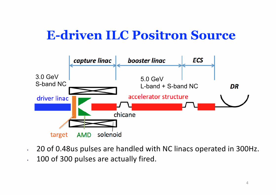
E-driven ILC Positron Source
3.0 GeVS-band NC
5.0 GeVL-band + S-band NC
• 20 of 0.48us pulses are handled with NC linacs operated in 300Hz.• 100 of 300 pulses are actually fired.
4

20 pulses, rep. = 300 Hz• 1 pulse = 2 mini-trains with gaps• 33x2 bunches/pulse, Tb_to_b = 6.15 n sec
DRTb_to_b = 6.15 n sec
1320 bunches/train, rep. = 5 Hz• Tb_to_b = 554 n sec
e+ creation go to main linac
Time remaining for damping = 137 m secWe create 1320 bunches in 63 m sec
Booster Linac5 GeVNC300 Hz
Drive Linac3 GeV NC300 Hz
TargetSlow Rotation
1320 bunches60 mini-trains
Stretching in time to reduce target heat load
E-driven Conventional e+ Source for ILCNormal Conducting Drive and Booster Linacs in 300 Hz operation
5

The beam handling and format
6

● 3.0 GeV Electron beam with 2.0 mm RMS beam size at the target.
● 3.7 nC bunch charge is giving 0.65 A beam loading.
● S-band Photo-cathode RF gun for the beam generation.
● 80 MW klystron-modulator drives 2 of 3m S-band structures.
● The effective input power for each tube is 36 MW.
3 GeV Electron Driver
7310 m

8

ferrofluid
Rotation Target
air vacuum
rotation at 225 rpm
ferromagneticfluid seal
e- beam
Motor
Ion pump
Target disk: Φ = 500 mm- Outer tungsten ring - Inner copper disk :
Water channels inside
BearingFerrofluidrotation vacuum
seal
Shaft: Coaxial water
channels inside
e+ Capture cavity
Bearing
Vacuum chamber
l W-Re 16mm thick.l 5 m/s tangential speed rotation (225 rpm,
0.5m diameter) in vacuum. l Water cooling through channel.l Vacuum seal with ferrofluid.
9

Long Term Vacuum and Rotation Test of the Target Prototype (on going)
The prototype has no target disk, but the design is compatible with the weight and the moment of the real target.
Collaboration with Hiroshima Univ.
Ion pump, vacuum gage, and residual gas analyzer were purchased by Hiroshima.
Vacuum gageResidual gas analyzer
Motor
Ion pump
Bearing Ferrofluidrotation vacuum
seal
Shaft: Coaxial water
channels inside
BearingVacuum chamber
Results : Long term Vacuum and Rotation Test of the Target Prototype・Base pressure of 6x10⁻⁷ Pa : achieved・This is 5 times better than the TDR requirement.・However we observed sudden jump of the pressure・The frequency of the jump was once per several hours and typical height of
the jump was x10 of the base. ・Next step: Two-stage vacuum seal to prevent the jump of the pressure. 10

ILC Flux Concentrator (FC)
e- beam
Similar design to the FC being operation at VEPP5 in BINP.
Pavel V. Martyshkin (BINP)
11

aperture 5.5mm (dia)
Nose type

25 kA5 T
25 micro sec100Hz (300 Hz)13.7 kW (41kW)
140 J/pulse
VEPP 5 FC ILC FC
dynamic force 120kA x 10T=1200 kA*T 25kA x 5T=125 kA*T
F. Emanov at al., RuPAC 2016
Comparison: VEPP FC (in operation) and ILC FC

Energy deposits on target, FC, and capture cavities (with Drive Beam Parameters)
Bunch charge 3.7 nC
If e+/e- yield ratio, 𝜂, equals to be 1.28, electrons of 3.7 nC create positrons of 4.74 nC.This corresponds 3 x 10¹⁰ positrons.
H. Nagoshi, et al., Nuclear Inst. and Methods in Physics Research, A 953 (2020) 16313414

15
The limit of the PEDD (Peak Energy Deposit Density) of W-Re alloy is 70 J/g. It was determined in the experiment at the end-station of the SLAC 2-mile linac. The often quoted 35 J/g is a number that includes a safety factor of 2 .
The value is important because it condition is similar to our condition.
SLAC-CN-128 (1981)
The 35 J/g: PEED

ILC: 33.6 J/gNe-/bunch = 2.3 x 10¹⁰ (x66 bunches gives 33.6 J/g)
PEDDIn View Point of instantaneous damage
SLC: 30.5 J/g Ne-/bunch = 4.2 x 10¹⁰ (The best vale in the SLC history)
16
Comparison of the SLC, KEKB, and ILC targets
Note:The SLC trolling target (rotation target) was used for 6 years, but the real high luminosity came out during the last run (1997 -1998) for 1 year. SLAC-PUB-9724 (2003)
SLAC-PUB-9724 (2003): Description of the last run 1997-1998. Ne- = 4.2 x 1010.PEDD = 30.5 J (scaling from the value in SLAC-PUB-9437)
SLAC-PUB-9437 (2002): PEDD calculation with Ne- = 4.0 x 10¹⁰ . The condition similar to the last run. PEDD = 29 J/g.
Produce Ne+/bunch ewuls to be 3 x 10¹⁰. This value include safety factor of 1.5.
KEKB: 29 J/g Ne-/bunch = 6.25 x 10¹⁰ (x2 bunches gives 29 J/g) achievement
In View Point of PEDD, all the three targets are similar.

ILC (rotation target, circumference = 1500 mm) :1300/66 x 5 Hz x 3600 s/h x 24 h/d x 365 d/y / 1500 mm= 2.1 E+6 hits/year.mm
In view point of Number of hit / year.mm (in the view point of Fatigue); ILC target (E-drivenl) 10 times ease than SLC target.ILC target (E-driven) is 800 times ease than KEKB target
Number of hit / Year.mmIn View Point of Fatigue Effect
Def. of hit, SLC: 1 hit = 1 bunch, KEKB: 1 hit = 2 bunches, ILC: 1 hit = 66 bunches
SLC (rotation target, circumference = 180 mm) : 120 Hz x 3600 s/h x 24 h/d x 365 d/y / 180 mm = 21 E+6 hits/year.mm
17
Note:The SLC trolling target (rotation target) was used for 6 years, but the real high luminosity came out during the last run (1997 -1998) for 1 year. SLAC-PUB-9724 (2003)Therefore, it is considered appropriate to think that "After a year of use, the people opened it and found a lot of cracks on the back (SLAC-PUB-9438).”
KEKB (fixed target, beam size in sigma = 0.426 mm):50 Hz x 5 Hz x 3600 s/h x 24 h/d x 365 d/y / 1 mm= 1580 E+6 hits/year.mm
Comparison of the SLC, KEKB, and ILC targets

l L-band accelerating structures of 2a=60 mm.l The linac is 71 m long and surrounded by 0.5 T solenoid magnets.
l There is a chicane at the down stream of the capture linac to remove electrons.
Positon Capture Linac
l There is a chicane at the down stream of the capture linac to remove electrons.
18

19

• A first half is implemented by L-band acc. and the last half is by S-band.
• 50MW L-band Klystron drives two L-band acc. (2a = 34 mm).• 80MW S-band Klystron drives two S-band acc. (2a = 20 mm).• The gradient at 0.78 A beam loading is assumed.
Positron Booster Linac
l There is a Energy Compensation System (ECS) at the down stream of the booster linac.
20

Simulation with assuming realistic components is on going
21
Coil Current260 AT/cm2
346mm44mm
210m
m
550m
m
355m
m
80m
m
400mm154mm
40mm
890m
m
current density of coil: 260A/cm2Coil length: 400mmSpace between coils: 44mmYoke thickness: 40mm
Coil shape of both end of accelerating tubes are modified to reduce the drop of the magnetic field at intervals of tubes.
Now our solenoid (71 m in total) is divided into many short pieces with spaces in between.
M. Fukuda

22
0deg10deg20deg30deg40deg
Capture linac phase
Target
FC
Distance between Target and FC[mm]
Ne+(DR) Yield(DR)
1.0 12601 1.26
2.0 12472 1.25
3.0 12042 1.20
4.0 11292 1.13
5.0 10646 1.06
Primary e-: 10000
Simulation with assuming realistic components gives us h = 1.25, at target-FC distance of 2 mm.
Scan of distance between Target and FC
Simulation with assuming realistic components is on going M. Fukuda
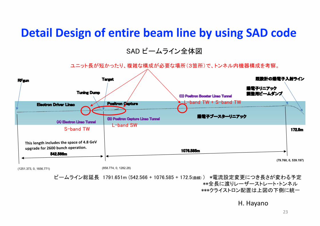
既設計の陽電子入射ラインRFgun
Electron Driver Linac Positron Capture
Target
陽電子ブースターリニアック
Tuning Dump陽電子リニアック
調整用ビームダンプ
(1251.373, 0, 1656.771) (858.774, 0, 1282.28)
(79.760, 0, 539.197)
1076.585m
172.5m
542.566m
ビームライン総延長 1791.651m (542.566 + 1076.585 + 172.5(曲線) ) *電流設定変更につき長さが変わる予定
SAD ビームライン全体図
ユニット長が短かったり、複雑な構成が必要な場所(3箇所)で、トンネル内機器構成を考察。
S-band TWL-band SW
L-band TW + S-band TW
(A) Electron Linac Tunnel(B) Positron Capture Linac Tunnel
(C) Positron Booster Linac Tunnel
**全長に渡りレーザーストレート・トンネル***クライストロン配置は上図の下側に統一
Detail Design of entire beam line by using SAD code
23
H. Hayano
This length includes the space of 4.8 GeV upgrade for 2600 bunch operation.

Total Length
1619 m
71 m
543 m
80 m
925 mInclude a space for 2600 bunch upgrade
24

25
Service Tunnel
E-Driven e+ Source Overall LayoutSection lengths
Tunnel Layouts
Accelerator Tunnel
Unit (m)
Plan View (schematic)
Total 1619 m
71 m543 m 80 m925 m
M. Kuriki
Note: The 545 m includes a space of 4.8 GeV upgrade for 2600 bunch operation.

Electron 3 GeV Driver
target, capture,and chicane Positron Booster ECS
e- GunRF Gun 1S-band Klystron 4 sets(1/set)S-band Modulator 4 sets(1/set)S-band Acc. Tube 1Solenoid 2Q Magnet 4Bending Magnet 5Steering Magnet 5
e- Drive Linac (S) (3.0 GeV)S-band Klystron 21 sets(2/set)S-band Modulator 21 sets(2/set)S-band Acc. Tube 21 sets(4/set)Q Magnet 53Bending Magnet 4Steering Magnet 50
e+ Capture Linac (L)L-band Klystron 22 sets (1/set)L-band Modulator 22 sets (1/set)L-band Acc. Tube 20.5 sets(2/set)Solenoid 71 m in total
Chicane & e+ Booster Linac (L+S)L-band Klystron 32 set(2/set)L-band Modulator 32 set(2/set)L-band Acc. Tube 32 set(4/set)S-band Klystron 27 set(2/set)S-band Modulator 27 set(2/set)S-band Acc. Tube 27 set(4/set)Q Magnet 351Bending Magnet 28Steering Magnet 171
ECS (L)L-band Klystron 1 sets (3/set)L-band Modulator 1 sets(3/set)L-band Acc. Tube 1 set(6/set)Q Magnet 34Bending Magnet 30Steering Magnet 17
Target
Number of Major Components
注:員数見積もりは3 GeV だがトンネル長は 4.8 GeV 対応
26

L-band (50 MW) (average 50 kW) x 99 4.950 MWS-band (80 MW) (average 80 kW) x 100 8.000 MW
Q-magnet (50 T/m, 32 mmf) ( 3.0 kW) x 57 0.171 MWQ-magnet (50 T/m, 50 mmf) (10.0 kW) x 425 4.250 MW
RF
Magnets
Solenoid in the Capture sectionSolenoid (0.5T, total length 71m) 1.420 MW
Bending Magnet (1 T, 3 m) (20.0 kW) x 49 0.980 MWSteering Magnet (30 W) x 263 0.008 MW
Total 19.8 MW
Power Consumption
27

Power Consumption and Cooling Water
Electron 3 GeV Driver
target,capture,and chicane Positron Booster ECS
e- Gun0.4 MW500 ℓ /m
e- Drive Linac (S) (3.0 GeV)3.6 MW4700 ℓ /m
e+ Capture Linac (L)2.5 MW3300 ℓ /m
Chicane & e+ Booster Linac (L+S)12.2 MW16000 ℓ /m
ECS (L)1.1 MW1600 ℓ /m
TargetTarget 1式
Total Power Consumption: 19.8 MWTotal Cooling Water: 25,900 ℓ/min
Note: We assume 1,310ℓ/min/MW is required for cooling. 28

Target Maintenance/Removal OperationWe studied many possibilities.
P. Sievers
J-Parc
Super-KEKBP. Sievers

30
Unit (m)
E-Driven Tunnel Target Section (Upstream of the target)
u To confine the radiation from the target, 2.0 m shield by BC surrounds the target module.
u The used target is stored in the cavern.
u The used target is transported to the cavern by a special wagon (Traverser).
Plan View
Target Maintenance/Removal Operation
M. Kuriki

Pillow SealTarget Maintenance/Removal Operation
S. Makimura, Y. Yamanoi

32
BC(boron-doped concrete)
ターゲットモジュール
BC鉄
Expected Activity in Target Maintenance/Removal Operationu By the front shield plate of
the target module (300mm BC and 200 mm Fe), the dose on front of the module is 50µSv/h.
u By putting 50 mm Fe shield by cask on Traverser, the dose on side of the module is 1 mSv/h.
u There is no shield on backside during the maintenance. The dose is in order of Sv/h. No access.
DOSE-EQ: after 1 year beam and 100 hours cooling (2625Bx, 5Hz)
A. Miyamoto

Separate tunnel for E-driven e+ Source
e- BDS tunnel (L=2.3 km, w =7.5 m)RTML
e-Driven e+ source tunnelaccess/exit
Separate tunnel dedicated for the E-driven e+ source; it will help flexible operation.
33
See, Yokoya’s talk in early morning (US Pacific) on 20-Oct-2020

34
l E-driven ILC positron source is optimized for 250 GeV ILC.l Everything can be ready before the engineering design in the
preparation phase. l E-driven positron source is independent from entire system, thus
it has big advantages in commissioning and availability.l Early commissioning and availability are essential for success of
the project.l Detailed design of entire beam line from stat to end is on going. l Design of tunnel with assuming real site is on going.l Evaluation of radiation dose is on going.l Design of target maintenance scheme is on going.
Summary
We are closing to“READY for CONSTRUCTION”

35
Backups

Comparison of the SLC target (design) and the ILC target : 1
The point of max von Mises stress(between two hits)
SLC (SLAC-PUB-5370 (1991)(surface)
ILC(surface)
Tensile stress 650 MPa 320 MPaCompressive stress 434 MPa (absolute vale) 550 MPa (absolute vale)Von Mises stress (SE) 965 MPa 760 MPaTemperature 370 C 350 CYield Strength 1380 MPa (370C) 1400 MPa (350 C)Comment SE is 70% of the yield strength, it
is OK. No comparison with fatigue stress.
SE is 54% of the yield strength. SE is 1.36 of the fatigue stress.
The point of beam hitThe point of max. temp.
SLC (SLAC-PUB-5370 (1991)(inside)
ILC (inside: 2mm from the surface)
Compressive stress 1240 MPa (absolute vale) 810 MPa (absolute vale = ABS(S3))Von Mises stress 600 MPa 470 MPa
Temperature 650 C 585 CYield Strength 1030 MPa (650C) 1230 MPa (585 C) Comment 1 The paper says “the material is
captured” so we assume not surface.All S1, S2, S3 are negative. Captured by compressive stresses in all directions.
Comment 2 The principal stress with the greatest absolute value. It’s 120% of the yield strength. But OK, because compressive.
36

Schematic of ferrofluid seal
ferrofluid 37