i.l.7418-b 1aooo inst allation instructions … · o plain (10 times interrupting capacity) ......
TRANSCRIPT

INST ALLATION • OPERATION •
I.L.7418-B Filing No. 11000 or 1AOOO
MAINTENANCE
INSTRUCTIONS
..A..M'PG..A..R.D* FOR INDUCTION
AND SYNCHRONOUS MOTORS
With High Intel'l"apting Capacity Cunent Limiting Fuses - NI.:MA Class 1.:2
FIG. 1. Typical Class 11-202-HS4FA Starter
*Trademark
SUPERSEDES I.L 7488-A
GENERAL
This instruction leaflet covers NEMA CLASS
E2 STARTERS having high interrupting capacity, current limiting fuses for control of squirrel cage induction or synchronous motors. The starters can be of the full voltage (Linestart) or reduced voltage type for reversing or non-reversing control. Reduced voltage starters may use autotransformers,
or reactors. The control for the primary of a woundrotor induction motor is basically the same as a full voltage starter for a squirrel cage motor. Synchronous motor starters are similar to squirrel cage induction motor starters, but include devices required for the application of excitation to the synchronous motor field. Starters can include a wide variety of extra features. These instructions, though written to apply specifically to full-voltage, nonreversing starters, are applicable, in general, to the whole line of high voltage starters.
CATALOG CLASSIFICATION
The table on page 2 lists the catalog class numbers of the starters covered by these instructions.
The assignment of class numbers is based on the following table. Each character of the designation describes a feature of the starter or motor to be controlled.
JANUARY, 1965 www . El
ectric
alPar
tMan
uals
. com

AMPGARD ________________________________________________________ _
INTERPRBTATION OF CLASS NUMBBRS 11 Type of Contactor and Voltage
11 . 2 0 2 H S 4 FA H Air Break Contactor, High Voltage (2300 volts and above) a Oil Immersed Contactor, High Voltage (2300 volts and above)
•••• II Type of Bnclosure
SNEMA1
a General Class Number
1 1 Squirrel Cage Magnetic 13 Wound Rotor Magnetic 14 Synchronous Magnetic
II Voltage Application
2 Linestarter 5 Reactor Starter
6 Auto-Transformer Starter
D NEMA 2 A NEMA 3
W NEMA 4 J NEMA 12
Z Other Enclosures to be Specified
II Contactor Size
1- 100 Ampere Contactor 2-200 Ampere Contactor
4-400 Ampere Contactor
II Suffix (when required)
II Speed, Reversing and Non-Reversing FA Front Accessible, 30" Deep RM Rubber Mill Control
o Single Speed, Non-Reversing
1 Single Speed, Reversing 3 Multi-Motor 4 Two-Speed, Single Winding, Non-Reversing 5 Two-Speed, Two Winding, Non-Reversing
6 Two-Speed, Single Winding, Reversing 7 Two Speed, Two Winding, Reversing 9 Multi-Speed (Over Two)
RB Rubber Banbury Control D2 Class 1, Group D, Division 2
a Interrupting Capacity and Disconnects
o Plain (10 times interrupting capacity)
Thus the example above represents a squirrel cage motor starter, full voltage, non-reversing, with current limiting fuses, air break contactor, 400 ampere size, in a front accessible NEMA 1 enclosure.
1 No Disconnects 2 Current Limiting Fuse 3 Non-fusible Disconnect
Table No.1
INTERRUPTING CAPACITY AND MAXIMUM HORSEPOWER RATINGS OF STARTERS
MOTOR VOLTAGE CONTACTOR INTERRUPTING MAXIMUM MOTOR HP AT 60 CYCLES 8 HOUR RATlNG*
80% PF SYN. l00� PF RATING 50 OR 60 CYCLES AND IND. MOTORS SYN. OTORS
2200 to 2400 100 150,000 350 450
200 150,000 700 900 400 150,000 1500 1750
4000 to 4600 100 250,000 625 750 200 250,000 1250 1500 400 250,000 2500 3000
·In terms of the maximum available symmetrical KVA at the starter incoming line terminals.
2 www . El
ectric
alPar
tMan
uals
. com

AMPGARD ________________________________________________________ �I�.L=.�74���B
FIG. 2 Class 1l·202HS4FA Starter showing Control Panel Behind Center Door
DESCRIPTION
General. These starters have a high.voltage air break or oil-immersed, contactor for normal motor load switching. High interrupting capacity, currentlimiting, fuses interrupt fault currents in excess of the contactor rating. A list of the instruction leaflets, for all devices included in a standard starter, is shown on page 10.
Enclosure. The induction and synchronous, full voltage, motor starters of the front accessible type, consist of a single basic structure approximately 38" wide, 30" deep and 90" high. This structure is floor-mounted, free-standing of welded and bolted construction with removable side, rear and top sheets. The general construction, arrangement of devices and the compartmentation for the control devices is shown in Figures 2 and 3. The reversing, reduced voltage and multi-speed starters require an additional structure, and are similar to the starter shown in Figure 6.
Isolating Switch. Standard Ampgard Starters are equipped with an isolating switch. The main power supply to the starter is connected to the line side of the switch. When the switch is in the "OPEN"
position, the load side contacts are connected to a common grounding bar.
The isolating switch is located in the upper section of the starter and is operated by the handle of the upper compartment door. The handle engages the isolating switch operating shaft only when the door is fully closed and the door can be opened only if the isolating switch is open. The handle is shown in Figure 4. The coupling and mechanism for operating the mechancial interlock is shown in Figure 5.
THE ISOLATING SWITCH HAS VERY LIMITED INTERRUPTING CAPACITY. DO NOT OPEN IT WHEN IT IS CONNECTED TO A LOAD OF ANY KIND. It will interrupt single phase control transformer magnetizing currents which do not exceed 0.75 KVA. Any load greater than this may not be interrupted and will become a three-phase to ground fault when the grounding contacts touch the grounding bar.
Main Powel' Fuses. In standard Ampgard Starters, non-disconnecting type fuse mountings are used for the main power fuses. They are located
FIG. 3 Class l4-202·HS4FA Starter Interior with all Doors Open
3 www . El
ectric
alPar
tMan
uals
. com

AMPGARD ________________________________________________________ ___
FIG. 4. Upper Door Handle. Operates Isolating Switch and Mechanical Interlock
FIG. 5. Coupling and Gear for Operating Isolating Switch and Mechanical Interlock
immediately behind the upper compartment door. The upper compartment door can be opened only if the isolating switch is open. However, to insure maximum safety, the position of the isolating switch should be checked visually before contacting any portion of the high volatge circuit. Once this check has been made, the fuses can be safely removed manually without the use of fuse clamps or tools.
4
Low Voltage Compartntent. Control relays, protective relays, and other auxiliary equipment which operates at low voltage, including the field contactor of synchronous motor starters, are mounted in the low voltage compartment. This equipment is front-connected and is mounted on a control panel which may be swung open to obtain access to the high voltage equipment behind it. The mechanical interlock allows the control panel to swing out only when the isolating switch is fully open and it blocks the closing of the isolating switch until the control panel is returned to its normal position.
Main Contactors. The main contactor may be either the oil-immersed or air air break type. It is mounted in the lower part of the structure, as shown in Figure 3. The contactor is interlocked with the isolating switch to prevent the opening of the isolating switch when the contactor is closed. The door of the contactor compartment can be opened only when the isolating switch is fully opened. An electrical interlock opens the closing circuit of the contactor when the isolating switch is open.
Reduced voltage, reversing, dynamic braking, and multi-speed starters require more than one contactor and often other high voltage equipment. Interlocking is provided for equipment in the auxiliary structure similar to that described above for the equipment in the basic structure.
Mechanical Interlock. The mechanical interlock prevents access to the high voltage compartments of the starter when the isolating switch is closed. It allows the isolating switch to be opened only when the contactor is open.
Refer to the paragraphs on isolating switch, main power fuses, low voltage compartment, and main contactor for specific operation of the mechanical interlock in relation to these components. The mechanical interlock functions as follows:
With the handle of the upper compadment door in the "ON" position
A-Isolating switch is closed B-Upper compartment door can not be opened C-�Control panel can not be swung out
D--Lower door can not be opened
E-The contact of the electrical interlock is closed. The main
contactor can be closed by operating the pushbutton or
other master element.
With the isolation switch in the "OPEN" position A-Upper compartment door can be opened or closed
B-Control panel can be swung out.
C-Lower compartment door can be opened or closed.
D-Electric interlock is open and the main contactor coil
can not be energized.
Isolating switch can be closed only when: A-Upper compartment door is closed
B-Control panel is in operating position
C-Lower door is closed
www . El
ectric
alPar
tMan
uals
. com
A�GARD ________________________________________________________ �I�.L�.�7����B
With the handle of the upper compartment door in the "LOCK-OPEN" position:
A-Isolating switch is open B--Upper compartment door can not be opened
C-Control panel can not be swung out
D-Lower door can not be opened
E-Elec!rical interlock is open and the main contactor can
not be dosed
The "LOCK-OPEN" position is used only when a lock is to be used to insure that the starter and its motor cannot be energized.
The isolating switch cannot be opened when the main contactor is closed.
Reduced voltage, reversing, multi-speed, and dynamic braking starters have high voltage equipment mounted in an auxiliary structure adjacent to the basic structure. The door of this structure is interlocked in the same manner as the lower door of the basic unit.
Control Circuit Transformer. Unless specifically ordered otherwise, a 400 VA Control Transformer is furnished. The primary is protected by
1fz Ampere, Type BAL, current· limiting fuses located behind the upper compartment door and connected
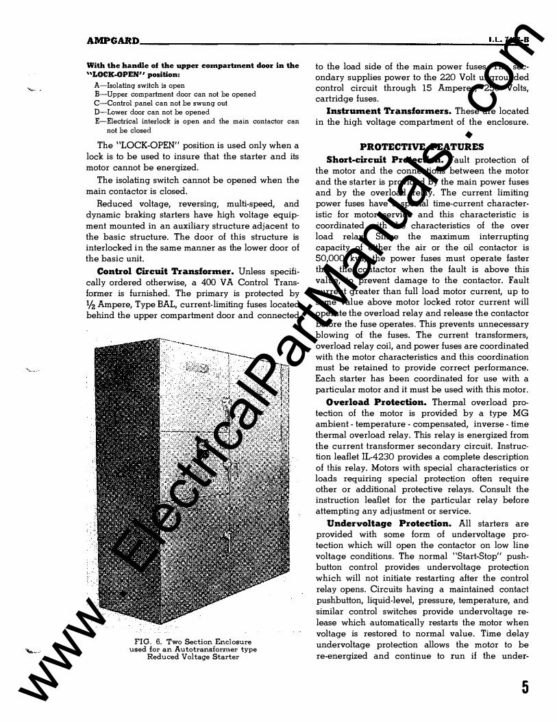
FIG. 6. Two Section Enclosure used for an Autotransformer type
Reduced Voltage Starter
to the load side of the main power fuses. The secondary supplies power to the 220 Volt ungrounded control circuit through 15 Amperes, 250 Volts, cartridge fuses.
Instrument Transformers. These are located in the high voltage compartment of the enclosure.
PROTECTIVE FEATURES
Short-circuit Protection. Fault protection of the motor and the connections between the motor and the starter is provided by the main power fuses and by the overload relay. The current limiting power fuses have a special time-current characteristic for motor service and this characteristic is coordinated with the characteristics of the over load relay. Since the maximum interrupting capacity of either the air or the oil contactor is 50,000 kva, the power fuses must operate faster than the contactor when the fault is above this value, to prevent damage to the contactor. Fault current greater than full load motor current, up to some value above motor locked rotor current will operate the overload relay and release the contactor before the fuse operates. This prevents unnecessary blowing of the fuses. The current transformers, overload relay coil, and power fuses are coordinated with the motor characteristics and this coordination must be retained to provide correct performance. Each starter has been coordinated for use with a particular motor and it must be used with this motor.
Overload Protection. Thermal overload protection of the motor is provided by a type MG ambient · temperature - compensated, inverse · time thermal overload relay, This relay is energized from the current transformer secondary circuit. Instruction leaflet JL·4230 provides a complete description of this relay. Motors with special characteristics or loads requiring special protection often require other or additional protective relays. Consult the instruction leaflet for the particular relay before attempting any adjustment or service.
Under voltage Protection. All starters are provided with some form of undervoltage protection which will open the contactor on low line voltage conditions. The normal "Start-Stop" pushbutton control provides undervoltage protection which will not initiate restarting after the control relay opens. Circuits having a maintained contact pushbutton, liquid-level, pressure, temperature, and similar control switches provide undervoltage release which automatically restarts the motor when voltage is restored to normal value. Time delay undervoltage protection allows the motor to be re-energized and continue to run if the under-
5 www . El
ectric
alPar
tMan
uals
. com

AMPGARD __________________________________________________ ______ _
voltage condition is for a limited time only. If the undervoltage condition continues beyond this limited period, the motor will not restart automatically when the voltage recovers. Modifications of these schemes may be supplied for special applications. It is therefore essential that the diagram packaged with each starter be consulted.
Synchronous Motor Field Application and Protection
Synchronous motor starters include type ASR Slipsyn or Static Slipsyn equipment to automatically apply the motor field when the rotor reaches the proper speed and is in the proper phase position. Refer to the diagram and the corresponding instruction leaflet for complete information.
In addition to the protection described in the preceding paragraphs, synchronous motor starters are equipped with damper winding and pull-out protection. These features are supplied as a part of the field application equipment. The damper winding relay operates from the current induced in the field windings during the starting period. This relay opens the main contactor circuit before the damper winding reaches an excessively high temperature.
The pull-out relay senses an out-of-step (nonsynchronous) conditions and is effective only after the field has been applied. It may be connected to open the main contactor and shut down the motor or open the field contactor and initiate resynchronizing. Refer to the wiring diagram to determine the connection for a particular starler.
INSTALLATION
Receivingl Handling and Storage. The high voltage starters are shipped in assemblies of not more than 3 structures bolted to a wood shipping skid. Heavy box board will enclose the sides, end, and top of the structure. A lifting angle is bolted to each end of the assembly for attaching hooks or a lifting sling so that the complete structure may be lifted by a crane. These lifting angles should be removed when no longer needed. Lifting by crane is preferable, but where crane facilities are not
available, the structure may be moved by use of rollers under the shipping skids. Although the base is of heavy formed sheet steel members, it is recommended that the skids be left in place while moving the assembly on rollers. It is also preferable
to place the structure in position or approximately so, before removing the box board shipping carlon. This gives protection against scratching or similar accidental damage in handling.
6
Upon receipt of the starter, it should have the box board shipping carlon removed to provide inspection against damage in transit. The exterior of the housing should be inspected for damage due to scratches or dents. The doors of the housing should be opened to make sure that none of the equipment has been broken or torn from its mountings due to rough handling in transit. Any indication of damage, should be reported to the carrier at once. If the equipment is to remain in storage or if it might be subjected to excessive dirt, rough handling, or damage due to accidental contact by workmen, it is recommended that the box board covers be replaced around the structures to provide physical protection.
Prior to placing the equipment in service, so that it«ill. �rate heat within the enclosure, it must be maintained in an atmosphere that will not permit sweating and condensation on metal parts. The degree of protection will be dependent on local atmospheric conditions. Space heaters mounted in each structure are recommended when the equipment is in an unheated building in winter. The addition of ventilating fans may be desirable in humid climates in summer. The equipment must be protected from excessive dirt and dust. Storage outdoors, even when protected by a tarpaulin, is inadequate, unless the enclosure is a weather-proof type.
Location and Foundation. The location of the starter should provide protection, accessibility and ventilation. The enclosures are designed for operating in a maximum ambient temperature of 30°C. The starter should be located as near the motor as practical and preferably in sight of the machine operator.
Starters should be installed on a true and level base. The structures should be bolted together. Bolting of the structure to the floor is desirable, but not essential, if the foundation is level and no shims are required to give supporl at the corners. Check the external connection diagram to determine the number of conduits required for cable connections. Check the National Electric Code or other applicable codes to determine conductor and conduit size.
Cable connections. The starters are furnished with provision for a separate supply circuit or for connection to a common bus which will feed two or more starlers. When a common bus is used, it is mounted in a separate enclosure above the starter structure as shown in Fig. No. 7. The supply circuit is connected direct to the bus. When the starter is to be supplied by a separate feeder circuit, the isolating switch cable connections terminate in a line
www . El
ectric
alPar
tMan
uals
. com

AJfPGARD ______________________________________________________ __ �I.�L�.7�4=88�-B
FIG. 7. View showing Left Side and Rear of Unit with Bus Enclosure on Top
enclosure terminal box as shown in Fig. No.8. The supply cable must enter the bottom of the line enclosure and connect to the solderless terminals. There is adequate electrical clearance between the terminals, but they may be taped, if desirable. The cover must be replaced to prevent accidental contact when the supply line is energized. The feeder cable to the motor should be connected to the air contactor as shown in Fig. 8 taking care that the cables do not interfere with the barriers between the contactor poles and that there is ample electrical clearance between the terminals and the front door. The supply cable, the feeder cable to the motor and
any remote control circuits can be supplied to enter the enclosure from either the top or bottom as shown in Fig. 9. Provision for top entrance is included only when requested. Bottom entrance is made between
FIG. 8. View of Contactor Suggested Arrangement of Feeder Cable to Motor
and Method of Splicing Main Power Cables in Line Enclosure. Main Contacts are Inspected and Maintained
with the Arc Chute Hinged Open as Shown.
the left side of the contactor and the structure. The available space is shown on the floor plan drawings furnished with the starters.
Jfakillg c::olltactors ready. The air-break contactors are shipped with the arc boxes or chutes and arc barriers separately packaged. These must be installed as described in I.E. 16-200-1 before the starter is energized. The arc chutes contain ceramic material and are fragile, thus must be protected from rough handling and shock. After installing the arc chutes and barriers, the contactor should be checked to determine that it operates freely. This is especially important for starters having two or more contactors mechanically interlocks. Operation of the contaclor will determine whether the interlocks are free or bind due to misalignment caused by shipping or handling.
Most air-break contactors are equipped with d-c operating coils and have a separate coil to release
the anti-bounce latch. Contactors having a-c operating coils also have the latch, but is actuated by the main operating coil. With either type, the latch must be manually released to allow operation of the magnet armature of the contador. A description of the operation and photographs of the latches are in
7 www . El
ectric
alPar
tMan
uals
. com

AMPGARD' ________________________________________________________ _
INCOMING CABLES TO MAIN
BUS. TOP OR BOTTOM ENTRANCE CONTROL
CONDUIT MOTOR
CONDUIT
POWER
SUPPLY
CONDUIT
FLEXIBLE CONDUIT
FOR CONTROL CIRCUIT
TOP ENTRANCE ONLY
I '""\
I
FLEXIBLE CONDUIT
FOR CONTROL CIRCUIT
TOP ENTRANCE ONLY
:: L
LINE ENCLOSURE
IS OMITTED WHEN
STARTER I S FED
FROM MA IN BUS
���T��7----- ---�� INCOMING CABLES
TO STARTER
TOP ENTRANCE
� _____ � ____ .��� MOTOR CABLES
POWER MOTOR SUPPLY CONDUI T
BOTTOM BOTTOM
ENTRANCE ENTRANCE
TOP ENTRANCE
VIEW FRONT VIEW
FIG. 9. Section Views of Structure Showing Routing of Power and Control Cables
the paragraph titled "Magnetic Latches" of InstrucBook I.E. 16-200-l.
The contactor may be closed manually by reach
ing behind the horizontal magnetic armature and releasing the latch with one hand while moving the front edge of the armature with the other hand.
The contactor and interlocks should operate freely; however, more closing force is required after the
8
contacts touch. The contactor may be operated electrically by removing the control transformer secondary fuses and connecting a separately fused 220 volt supply to the load side of the fuse block. The secondary circuit must be opened by removal of the fuses, to prevent feedback of high voltage
through the control transformer. To provide addi
tional safety from high voltage, the control trans-
www . El
ectric
alPar
tMan
uals
. com

AWoIPGARD ______________________________________________________ �I�.L�.�7"���B
former primary fuses should be removed and the fuse clips short circuited on the transformer side. The isolating switch should be open.
Oil-immersed contactors are shipped dry with the oil in 5 gallon cans, except in cases where the total quantity of oil required, approaches a drum shipment. Before energizing the contactor, it must be filled with oil. The tank must be lowered for filling. Refer to LB. 16-200-2 for instructions on operating the tank lifter. The oil level should be at the mark inside the tank when it is down and at the line shown on the oil gauge when in place. This oil is similar to transformer oil and should be handled with the same care to prevent contamination.
The oil contactor should be operated manually when the tank is down to determine that it operates freely. Electrical operation for test may be obtained
in the same manner as described above for the air contactor.
Start-up Pl'ecautions. Before attempting to put a newly installed starter into service, study, the wiring diagram and available instruction literature. Be sure that:
I-The corresponding starter and motor are connected as shown on the Westinghouse drawings. This is particularly essential in this class of motor starters as the fuse ratings, current transformers, and overload heater elements are based on the characteristics of the particular motor to be controlled.
2-The starter is connected to a suitable power supply with characteristics agreeing with motor and control nameplate markings.
3-The mechanical and electrical interlocks operate freely, are properly adjusted, that all bolts and nuts are tight, and that they will operate to provide the protection intended.
4-The motor and machine it drives are properly lined up, bolted down, lubricated, free of obstructions, and ready to go.
S-Connections are neat, tight, of proper capacity and in agreement with diagram. Devices should be inspected for connections that might have
worked loose in shipment.
6-Main fuses have been installed, arc chutes are
in place on air contactors and oil contactors are
filled with oil of proper grade and to the correct
depth.
7-Equipment has been cleaned of dirt, scraps of wire, tools, temporary bracing and all other
foreign material.
8-All possible safety precautions have been taken and the installation conforms with applicable safety codes.
WoIAIN'TENANCE IN' OPERATING, SERVICING AND ADJUSTING
THE EQUIPWoIENT
Ampgard starters should be operated by authorized personnel only. Personnel authorized to operate the isolating switch and those authorized to inspect, adjust, or replace equipment inside the enclosure should have a complete understanding of the operation and limitations of the starter and must have thorough training in the safety precuations to be followed when working with dangerous voltages.
Before attempting maintenance, consult the specific diagram and the general and specific device instruction leaflets and particularly note the following points:
I-WARNING. All circuits must be de-energized when working on the equipment.
2-The equipment should be kept clean at all times. Maintenance should be competent and systematic. Infrequent operation of the starter should not be used as an excuse to defer inspection and maintenance. However, starters which are used on heavy duty cycles should have more frequent inspection than those which are started only a few times per day.
3-Worn contacts should be replaced before they cause a serious failure. Proper spring pressure should be maintained at all times. In general, a starter will give better service when it is repaired with authentic parts and is carefully maintained in line with Westinghouse recommendations.
4-Do not use emery paper around the electrical apparatus. Sand paper or file, only when absolutely necessary, and use care to avoid embedding metal particles in the insulating material or sand particles in the contact faces.
The controller and the fuses should be inspected after each fault clearing operation as this is the most severe service to which they will be subjected. The high voltage fuses should be checked to make sure that they have not blown before attempting to place
the starter in service. The same type and style
number of high voltage fuses must be used for
replacements in all cases.
Removing the WoIain Contactol'. The high
voltage contactor can be quickly removed and
replaced when necessary, but its removal should seldom be required. All contactor coils and parts
9 www . El
ectric
alPar
tMan
uals
. com

AMPGARD __________________________________________________________ _
subject to wear can be replaced with the contactor in place in the structure.
To remove the contactor:
I-Remove the arc chutes and barriers.
2-Disconnect the motor feeder cables on the front of contactor, the line side cables at the rear and the control cable at the right side.
3-Remove the two machine screws along the left hand side of the base which fastens the starter to the support members. This is most easily accomplished using a 3;"''' socket wrench with 12" extension.
4-Slide the contactor approximately 2 inches to the left, so that the foot on the right of the base is withdrawing from the slot in the right hand
support.
5-Slide the contactor forward and out of the
compartment.
The contactor may be replaced by reversing the procedure outlined above. Make sure that the interlocks are aligned and that all electrical connections are tight.
High Voltage Current Limiting Fuses. The mechanical interlock insures that the high voltage supply to the starter is disconnected by the isolating switch before the door over the fuses can be opened. With the door open, the position of the isolating
switch can be visually checked and the high voltage fuses can be safely removed, manually, without tools.
The high voltage, current limiting, Type BAL fuses, rated 112 ampere for protecting the primary
of the control and potential transformers are mounted in the right hand side of the upper compartment, as shown in Fig. 3. These fuses should rarely require replacement as any fault on the secondary circuit of the transformer will be cleared by the low voltage fuses.
The Type CLS-l and CLS-2 main power fuses used in Ampgard starters are self-protecting. Any fuse which has not operated to interrupt an overcurrent can be safely left in service. Starters manufactured before these fuses were available are equipped with Type BAL-LR fuses. The resistance of BAL-LR fuses should be checked periodically, after every abnormal overcurrent condition, and whenever one or more fuses in a group of three blows; to insure the fuse is in satisfactory operating condition. Information on test procedures and normal resistance values, if required, is included with the instruction book prepared for the particular job.
INQUIRIES
When ordering parts or making any inquiry regarding the starter, include the data shown on the rating nameplate mounted in the lower-left corner of the control panel (see Fig. No. 3). The essential data is stamped on the plate and should be readable even if the wording is illegible. Address all inquiries and requests for instruction leaflets to the nearest Westinghouse Sales Office.
LIST OF PUBLICATIONS APPLYING TO DEVICES USED IN THESE STARTERS
SUBJECT OR DEVICE INSTRUCTION RENEWAL PARTS BOOK NO. DATA NO.
HV Contactor-Air bre ak LB. 16-200-1 16-200Al HV Contactor-Oil immerse d I.B. 16·200·2 (Not Available)
Isolating Switch (Non e) 11·01lA
Overlo a d relay-Type MG I.L. 4230 15·827A17 Control relay-Type BF
Damper prot. relay-Type DP LL. l5·827·DP·l 15-827A12 T iming relay-Type AZ I.L. I5·827·7·AZ 15·827A2
T iming relay-Type AM I.L. 10234 I 5·827A 1 1
Syn . relay-Type ASR LL..l4·000·l l5·827A20 Static slipsyn syn . mot. c ont. LL.·l4·000·2 (Not Ava ilable)
Fi eld Cont.-Type M·221·2H LL. 15·800·M·021/121/221.1 15·801A5 Fi eld Cont.-Type MM·321 I.L. 10248 15·BOIBI
10 www . El
ectric
alPar
tMan
uals
. com

AMPGARD ______________________________________________________ ___
o
MANUFACTURING AND REPAIR DIVISION PLANTS
ATLANTA M & R 1250 Chattahoochee Ave., N.W. P.O. Box 4538 Atlanta, Georgia
BOSTON M & R 235 Old Colony Avenue So. Boston 27, Mass.
CHICAGO M & R 3900 W. 41st Street Chicago 32, Illinois
CLEVELAND M & R 4600 W. 160th Street Cleveland 35, Ohio
CINCINNATI M & R 1050 Laidlaw Avenue Cincinnati 37, Ohio
HOUSTON M & R 5730 Clinton Drive Houston 20, Texas
LOS ANGELES M & R 18020 S. Santa Fe Avenue Compton, California
NEWARK-HILLSIDE M & R 1441 Chestnut Avenue Hillside 5, New Jersey
PHILADELPHIA M & R Erie Avenue & D Street Philadelphia 34, Pa.
WESTINGHOUSE GENERAL CONTROL DIVISION
ELECTRIC •
ST. LOUIS M & R 1601 South Vandeventer Avenue St. Louis 10, Missouri
SEATTLE M & R 3451 East Marginal Way Seattle 4, Washington
SUNNYVALE MFG. DIVISION Hendy Avenue Sunnyvale, California
CORPORATION BUFFALO 5, N. Y.
printed in U.S.A.
11 www . El
ectric
alPar
tMan
uals
. com

www . El
ectric
alPar
tMan
uals
. com