iki t600 chimney · 2 iki t600 chimney installation instructions before installation ‐ check that...
TRANSCRIPT

IKI T600 CHIMNEY
Installation instructions 09/2017

1

2
IKI T600 CHIMNEY INSTALLATION INSTRUCTIONS BEFORE INSTALLATION
‐ Check that all the parts you need are included in the delivery, using the list of parts as reference (pp. 3‐5).
‐ Before piling the stones on the stove and installing the chimney, make sure the stove is horizontally levelled
and aligned with the hole in the ceiling.
‐ The safety distance from the outer surface of the flue pipe to inflammable surfaces in a well‐ventilated space
is 50 mm in each direction. Do not attach any materials to the surface of the flue unless it comes with a class
A1 fire rating. The safety distance from the top of the damper to the ceiling is 40 cm.
‐ The ceiling or wall may have maximum 2 metre overflow after the last support.
‐ The parts for the flue and chimney must be used as they come, and may not be altered or cut. The joints of
the pipe sections are secured with tightening straps.
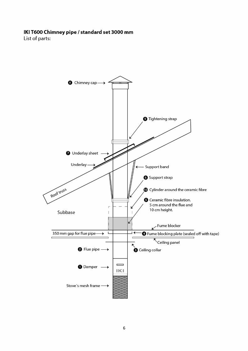
INSTALLATION INSIDE THE SAUNA ROOM (PICTURES ON PAGES 7‐8)
1. Install the damper (part 1) on top of the stove’s mesh frame, fasten securely. Position the damper panel to
the correct direction in the sauna room (Picture 1).
2. Pass the 1‐metre flue pipe (part 2) through the collar (part 3) (Picture 2).
3. Place the 1‐metre flue pipe (part 2) directly on top of the damper (part 1) (Picture 3). The ceiling collar can
simply rest on top of the damper at this stage of installation.
4. Place the tightening strap (part 9) to the joint of the damper (part 1) and the 1‐metre flue pipe (part 2) and
tighten securely (Picture 4). Attn! The joint between the damper section and the flue pipe may not need a
tightening collar if they fit securely as they are.
5. Use the tape provided to secure the fume blocking plate (part 4) to the fume block in the ceiling tightly
(Picture 5). There needs to be a 2‐mm gap between the fume blocking plate and the pipe, which is then taped
shut.
6. Attach the collar to the ceiling with the screws (4 pieces) provided in the installation gear box (Picture 6).
Detach the protective plastic from the collar.
INSTALLATION IN SUBBASE (PICTURES ON PAGES 7‐8)
7. Place the ceramic fibre insulation (part 5) once around the flue pipe. Minimum height 10 cm and minimum
thickness 5 cm (Picture 7). Attn! The flue pipe joint must not be located inside the fibre insulation.
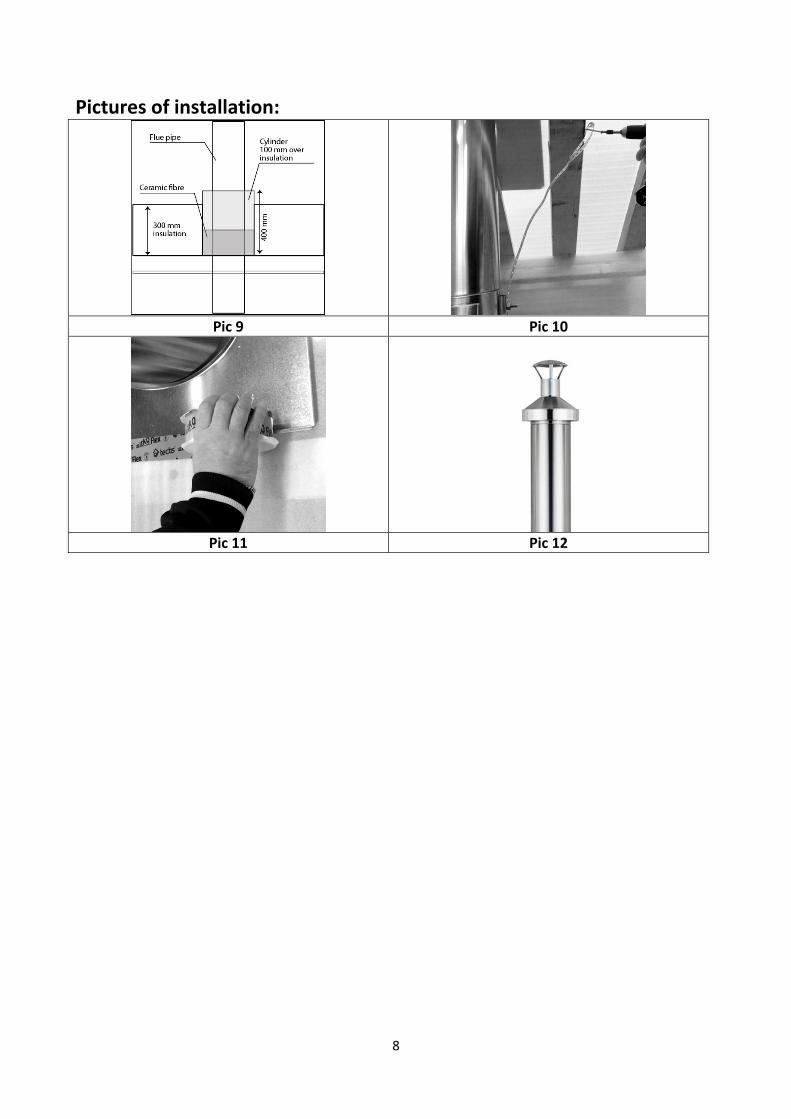
8. Bend the cylinder (part 10) around the fibre insulation (Picture 8). The cylinder needs to be at least 100 mm
higher than the insulation (Picture 9.) The standard cylinder included is 500 mm in height. If your insulation is
more than 400 mm in height, you need to increase the cylinder height by using another (supplementary)
cylinder and tape the two cylinders together.
9. Attach the second 1‐metre flue pipe section (part 2) on and secure the joint with a strap (part 6). Secure
bunched tape on to the strap and attach to roof trusses with screws (Picture 10).
INSTALLATION ON THE ROOF (PICTURES ON PAGES 7‐8)
10. Attach the underlay sheet (part 7) to the underlay leaving a 10 mm air gap from the pipe surface (picture 11).
The gap between the edge of the raised underlay and the chimney pipe is left open for ventilation.
11. Attach the last 1‐metre flue pipe section (part 2) in place on the roof.
12. SUPPLEMENTARY EQUIPMENT: Install the sheet metal set (IKI light or IKI full) around the chimney according
to separate installation instructions. If you want to use different sheet sets with the installation, they need to
be ventilated. It is forbidden to use products not part of the IKI chimney pipe system with this chimney
without the manufacturer’s written consent.
13. Place the rain cap (part 8) on to of the chimney (Picture 12).
3
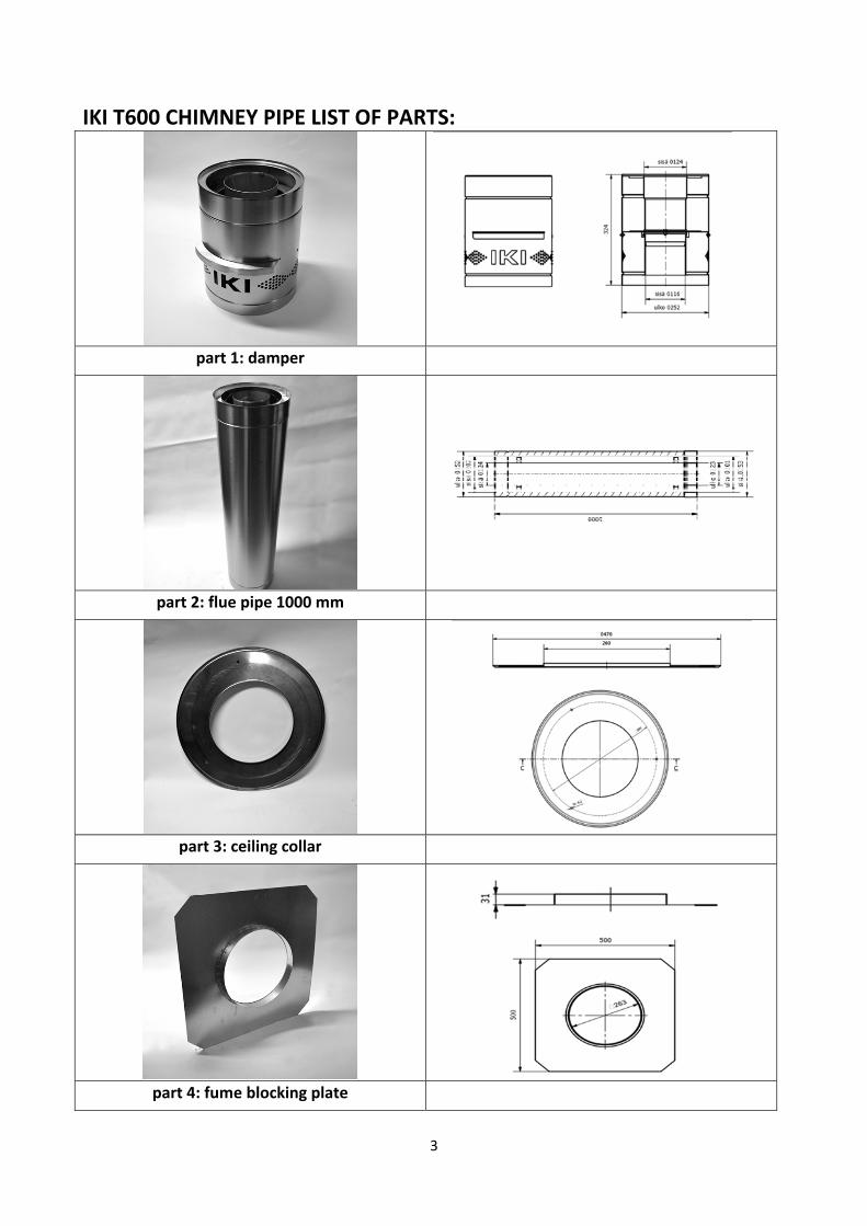
IKI T600 CHIMNEY PIPE LIST OF PARTS:
part 1: damper
part 2: flue pipe 1000 mm
part 3: ceiling collar
part 4: fume blocking plate

4
IKI T600 CHIMNEY PIPE LIST OF PARTS:
part 5: ceramic fibre insulation
part 6: support strap
part 7: underlay sheet
part 8: chimney cap
5
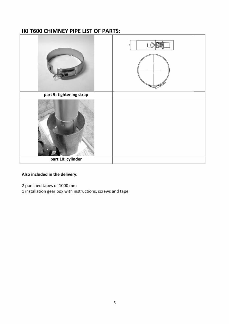
IKI T600 CHIMNEY PIPE LIST OF PARTS:
part 9: tightening strap
part 10: cylinder
Also included in the delivery: 2 punched tapes of 1000 mm 1 installation gear box with instructions, screws and tape
6

7
Pictures of the installation:
Pic 1 Pic 2
Pic 3 Pic 4
Pic 5 Pic 6
Pic 7 Pic 8
8
Pictures of installation:
Pic 9 Pic 10
Pic 11 Pic 12

9
Chimney height on roof top
Instructions for use Chimney details Damper The damper panel needs to be open whenever there is fire burning in the hearth, to not prevent air cooling! Snow barrier There needs to be a snow barrier on the upper side of the chimney to prevent damage to chimney. Sweeping The chimney may only be swept with a stainless steel or fibre brush. Product plate The mechanic will fill in the required information regarding the product to the plate included in the delivery. It should be placed somewhere easily visible. If necessary, the chimney needs to be protected from contact with external forces.
IKI T600 CHIMNEY PIPE CE 1450‐ CPR‐ 0007 EN 1856‐1 T600‐N1‐D‐Vm‐L99080‐G(50) Temperature class T600 Safety distance to inflammable structures 50 mm. Three‐sheathed air‐ventilated steel flue and chimney system. Warranty The manufacturer, Hormex Oy, Harkkoraudantie 6, 00700 Helsinki, issues a 10‐year warranty for materials and production errors for the flue and chimney system. The warranty does not cover for faulty installation.

10

11
Copyright © IKI‐Kiuas Ltd.