iir digital filter design
TRANSCRIPT
1
IIR Digital Filter Design
Standard approach
(1) Convert the digital filter specifications into an analogue prototype lowpass filter specifications
(2) Determine the analogue lowpass filter transfer function
(3) Transform by replacing the complex variable to the digital transfer function
)(sHa
)(zG
)(sHa
2
IIR Digital Filter Design
• This approach has been widely used for the following reasons:
(1) Analogue approximation techniques are highly advanced
(2) They usually yield closed-form solutions
(3) Extensive tables are available for analogue filter design
(4) Very often applications require digital simulation of analogue systems
3
IIR Digital Filter Design
• Let an analogue transfer function be
where the subscript “a” indicates the analogue domain
• A digital transfer function derived from this is denoted as
)(
)()(
sD
sPsH
a
aa
)(
)()(
zD
zPzG
4
IIR Digital Filter Design
• Basic idea behind the conversion of into is to apply a mapping from the s-domain to the z-domain so that essential properties of the analogue frequency response are preserved
• Thus mapping function should be such that
– Imaginary ( ) axis in the s-plane be mapped onto the unit circle of the z-plane
– A stable analogue transfer function be mapped into a stable digital transfer function
)(sHa )(zG
j
5
IIR Digital Filter: The bilinear
transformation
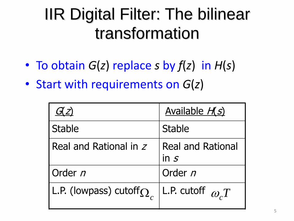
• To obtain G(z) replace s by f(z) in H(s)
• Start with requirements on G(z)
G(z) Available H(s)
Stable Stable
Real and Rational in z Real and Rational in s
Order n Order n
L.P. (lowpass) cutoff L.P. cutoff Tcc
6
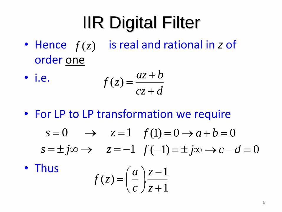
IIR Digital Filter • Hence is real and rational in z of
order one
• i.e.
• For LP to LP transformation we require
• Thus
)(zf
dcz
bazzf
)(
1 0 zs 00)1( baf
1 zjs 0)1( dcjf
1
1.)(
z
z
c
azf
7
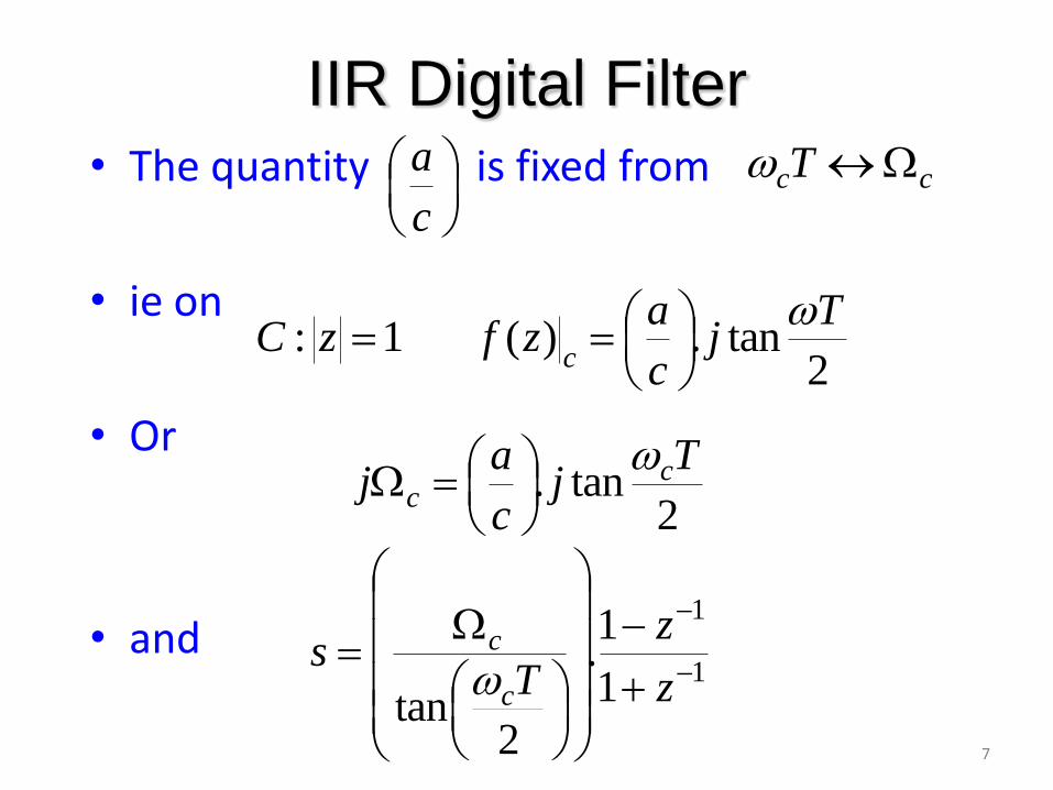
IIR Digital Filter • The quantity is fixed from
• ie on
• Or
• and
c
accT
2tan.)( 1:
Tj
c
azfzC
c
2tan.
Tj
c
aj c
c
1
1
1
1.
2tan
z
z
Ts
c
c
8
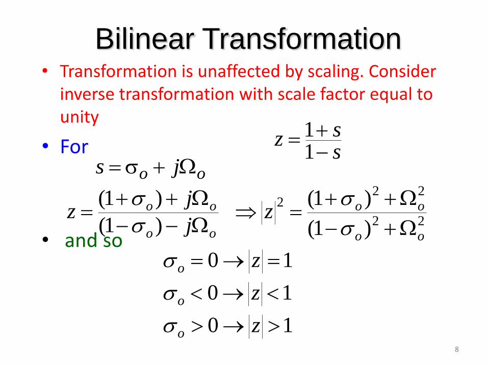
Bilinear Transformation • Transformation is unaffected by scaling. Consider
inverse transformation with scale factor equal to unity
• For
• and so
ssz
11
oo js
22
222
)1(
)1(
)1(
)1(
oo
oo
oo
oo zj
jz
10 zo
10 zo
10 zo
9
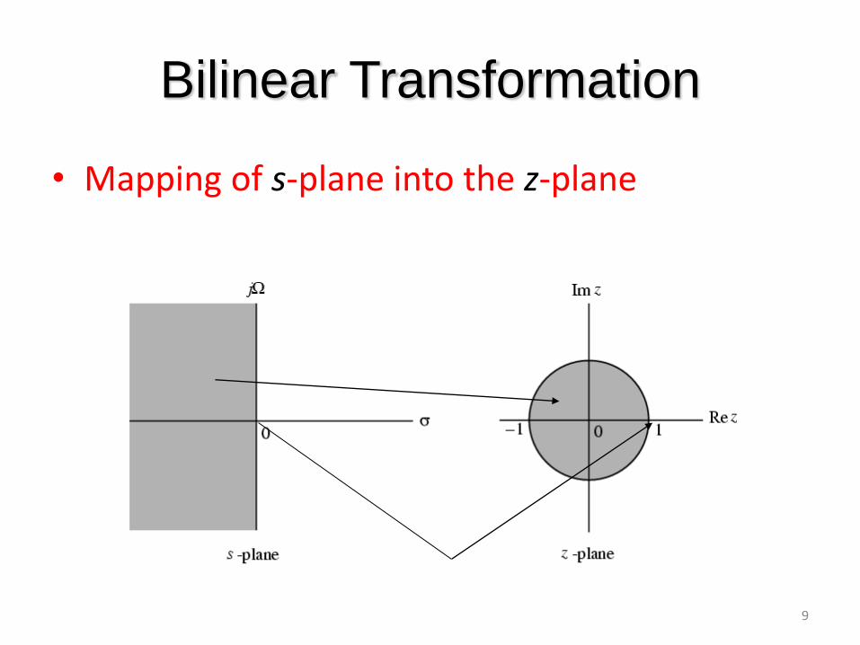
Bilinear Transformation
• Mapping of s-plane into the z-plane
10
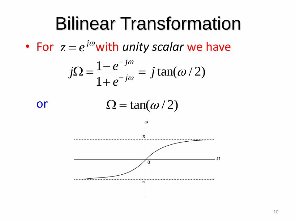
Bilinear Transformation • For with unity scalar we have
or
)2/tan(1
1
je
ejj
j
jez
)2/tan(
11
Bilinear Transformation
• Mapping is highly nonlinear
• Complete negative imaginary axis in the s-plane from to is mapped into the lower half of the unit circle in the z-plane from to
• Complete positive imaginary axis in the s-plane from to is mapped into the upper half of the unit circle in the z-plane from to
0
0
1z 1z
1z 1z
12
Spectral Transformations
• To transform a given lowpass transfer function to another transfer function that may be a lowpass, highpass, bandpass or bandstop filter (solutions given by Constantinides)
• has been used to denote the unit delay in the prototype lowpass filter and to denote the unit delay in the transformed filter to avoid confusion
)(zGL
)ˆ(zGD
1ˆz
1z)(zGL
)ˆ(zGD
13
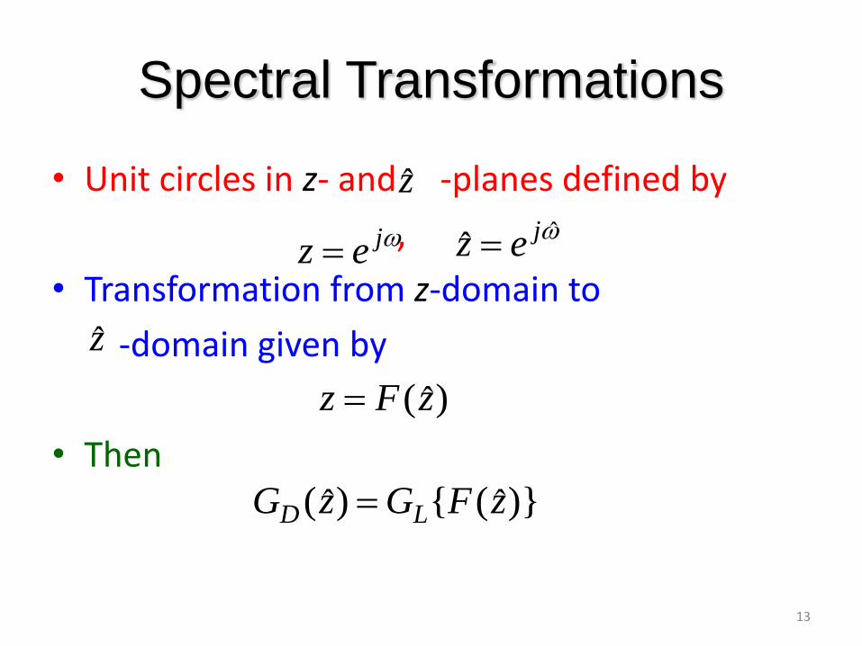
Spectral Transformations
• Unit circles in z- and -planes defined by
,
• Transformation from z-domain to
-domain given by
• Then
z
z
jez
ˆjez
)ˆ(zFz
)}ˆ({)ˆ( zFGzG LD