iiiiiiiieeeiie .iiiieeiiiieee mhhommhmhmhhhhl · aoaioi 558 stevens inst of tech hoboken nj...
TRANSCRIPT

AOAIOI 558 STEVENS INST OF TECH HOBOKEN NJ DAVIDSON LAB F/G 19/3AN EVALUATION OF THE COUPLED LVT CONCEPT.(U)NOV 79 I 0 KAMM, P W BROWN. P M BRADY N0001R-79-C-0356
UNCLASSIFIED SIT-DL-79-9-2082 NL201/10000000I00
mhhommhmhmhhhhl
IIIIIIIIEEEIIE.IIIIEEIIIIEEE

PHOTOGRAPH THIS SHEET
,A
LEVEL eoen. **OR- ,A
DOCUMENT IDENTIFICATION
poj4.. ~S1 vq
DISTRIIBUTION STATEMENT
ACCESSION FORNTis GRAMI
DIC TAB) 0 TUNANNOUNCED 0D IJUSTIFICATION Pr98CT
BY DDISTRIBUT'ION/AVAILABILIT Y CODESDIST AVAIL AND/ORt SPECIAL DATE ACCESSIONED
DIST RIBUTION STAMP
81 7 17 006DATE RECEIVED IN DTIC
PHOTOGRAPH THIS SHEET AND RETURN TO DTIC-DDA-2
DTCFORM 7ADOCUMENT PROCESSING SHEET

R-208
DAVIISON\
LABOR ATo)I
Report Number SIT-DL-79-9-2082
November 1979
AN EVALUATION OF THE COUPLED LVT CONCEPT
by:
Irmin 0. KammPeter W. Brown
Peter M. Brady, Jr.
Prepared for:
David Taylor Naval Ship Researchand Development Center
Code 112Bethesda, MD 20084
Under:
Office of Naval ResearchContract No. NOOO14-79-C-0356
NR 062-636
DISTRIBUTION UNLIMITED

UNCLASSIFIED
PI, I+A1) I ' C I rt ( ),N( QN
REPORT DOCUMENTATION PAGE PFAU1N , <,'. .REPORT NUMBER 2. *,OVT ACCESSION NO.1 3 RECIPILNT'S CATA-G NUMbER
SIT-DL-79-9-2082
4 TITLE (and 1,P+,u.tjlt 5 TYPEL OF REPORT 8 PERI , COVE4CN D
AN EVALUATION OF THE COUPLED LVT CONCEPT FINAL: 12 March 1979to 30 November 1979
6 PERFOR14ING OR3 REPORT NuMiE-LN
7+ AU THORn) 8 CONTRACT OR GRANT NUMBER(.)
I. 0. Kamm, F. W. Brown, P. M. Brady, Jr. N00014-79-C-0356
9 PERFORMING ORGANIZATION NAME AND ADDRESS 10. P;-,) GRAM E, EM, NT. PRO'J;'7. TASKAREA l wORK< UNIT NUMBERS
Stevens Institute of Technology A
Davidson Laboratory, Castle Point StationHoboken, NJ 07037 __
II. CCNTROLLING OFFICE NAME AND ADDRESS 1 17 REPORT DATEDavid Taylor Naval Ship Research and Developmen: November 1979
Center, Code 112 13 NIMBER OF PAGES
Bethesda, MD 20084 16oI4 MONITORiNJ AGENCY NAME A ADDRES(II different Iom ConfIollirn OIIIc.) 15 SECURITY CLASS (of Ihle roport)
Office of Naval Research UNCLASSIFIED800 N. Quincy St.Arlington, VA 22217 SC T N ONLE
16. DISTRIBUTION STATEMENT (ol this Repnrf)
Approved for Publ ic Release, Distribution Unlimited.
17. DISTRIBUTION STATEMENT (of rho abstract entered In Block 20, II diffeet from .raprI)
I8. SUPPLEMENTARY NOTES
19. KEY WORDS (C-tl lnue on rotor,,, aie )1 noroosary ernd identllv by block riuonber)
Linding Vehicles Amphibious Vehicles Hydrodynamic PerformanceCo'jpling Systems Off-road Mobil ity Sea KeepingControl Systems Vehicle PerformanceArticulated Vehicles Military Vehicles
20 A STROCT (Conlnt, on r ,..e *tI. If n- ay jsnd IdenIty by blnk n-.nhr)
The feasibility of coupling a pair of amphibious tracked vehicles has beenstudied, with the objective of improving the land and water performance.
Recommendations are made for a coupling system and its controls and for anarticulated configuration. The advantages in land and water performance, aswell as the drawbacks, are presented in comparison to single vehicles.
The advantages exceed the drawbacks, it is recommended that existing vehicles
be coupled and tested to establish their operational capability.
DD I ,AN ,3 1473 tO!TI N rI NOV I' IS OBSOLETE UNCLASS IF I ED.T/N A'l' CA4"601 .. .......... .. ..... ..
SECUIRITY CLAS3;" IC&1- ;',F r HIS I'liGE (Wh-en ltm~i ,.'l )

STEVENS INSTITUTE: OF TECHNOLOGYDAVIDSON LABORATORYCASTLE POINT STATIONHOBOKEN. NEW JERSEY
REPORT NUMBER SIT-DL-79-9-2082
November 1979
AN EVALUATION OF THE COUPLED LVT CONCEPT
BY:
Irmin 0. KammPeter W. Brown
Peter M. Brady, Jr.
Prepared for:
David Taylor Naval Ship Researchand Development Center
Code 112Bethesda, MD 20084
Under Contract:
Office of Naval ResearchNO00l 4-79-C-0356
NR 062-636
(DL Project No. 4706/058)
APPROVED:
Daniel Savitsky
Deputy Director
Distribution of this report is unlimited.

R -? o82
ABSTRACT
The feasibility of ccupling a pair of amphibious tracked vehicles
has been studied, with the objective of improving thie land and water
performance.
Recommendations are made for a coupling system and its controls
and for an articulated configuration. The advantages in land and
water performance, as well as the drawbacks, are presented in compari-
son to single vehicles.
The advantages exceed the drawbacks, it is recommended that
existing vehicles be coupled and tested to establish their operational
capabil ity.
KEY WORDS
Landing Vehicles Amphibious Vehicles
Coupling Systems Off-road Mobility
Control Systems Vehicle Performance
Articulated Vehicles Military Vehicles
Hydrodynamnic Performance Sea Keeping

R0;'82
TABLE OF CONTENTS
ABSTRACT. .. ............ .................
KEY WORDS. .. .............................
LIST OF TABLES .. .. .......................... iv
LIST OF FIGURES. .. .......................... V
1.1 EXECUTIVE SUMMARY .. .. .....................
2.1 CONCLUSIONS .. .. ........................
2.2 RECOMMENDATIONS. .. ............... ..........
3.1 INTRODUCTION. .. ........................
3.2 BACKGROUND. .. .......................... 6
3.3 OBJECTIVES. .. .......................... 7
4.1 CONSTRAINTS AND ASSUMIPTIONS. .. .............. .... 9
5.1 CONCEPT DESIGN AND ANALYSIS .. .. .............. ....
5.1.1 Coupled Vehicles. .. ................ .... 14
5.1.2 Articulated Vehicles .. .. ................. 16
5.1.3 Quick Disconnect Coupling. .. ............... 18
5.2 CONTROLS .. ............... ............ 19
5.2.1 Background Experience. .. ................. 19
5.2.2 Engine Locntrol .. ..... ................. 23
Coupled V'ehi'1es .. ... .................. 23
Articulated Vehicles .. ... ................ 23
5.2.3 Transmission Range Selection .. .. ............. 23
5.2.4 Brakes. .. ............... ......... 24
5.2.5 Steering in Pitch and Yaw. .. ............... 24
Coupled Vehicles .. .. .................... 4
Articulated Vehicles. .. ............... ... 24
5.2.6 Coupling Connect and Disconnect. .. ........... 25
5.2.7 Water Steering .. .. .................... 25
5.2.8 Miscellaneous. .. ..................... 26
Coupled Vehicles .. ... .................. 2'
Articulated Vehicles .. ... ................ 26

R -? 082
TABLE OF CONTENTS (CONTINUED)
6.1 LAND PERFORMANCE .. .. ...................... 27
6.1.1 Tractive Effort. .. ........... ......... 27
6.1.2 Acceleration. .. ..................... 27
6.1.3 Soft Soil Performance. .. .......... ....... 29
6.1.4 Obstacle Negotiation .. ............ ...... 30
Step Climbing. .. ........... .......... 30
Trench Crossing. .. ............ ........ 31
Climbing of Natural Terrain Feature Obstacles .. .. .... 32
6.1.5 Water Exiting. .. ........... .......... 33
6.1.6 Corridor Turning .. ........... ......... 33
6.1.7 Cross Country Ride .. ......... .......... 35
6.1.8 Land Summary .. .......... ............ 35
6.2 WATER PERFORMANCE .. .......... ............. 36
6.2.1 Model Description. .. ........... ........ 36
6.2.2 Test Program .. ........... ........... 37
6.2.3 Test Results .. ............ .......... 39
6.2.4 Full-Scale Predictions .. .............. ... 39
Single Vehicle in Calm Water .. .......... .... 39
Coupled Vehicle in Calm Water. .. ............. 4o
Seakeeping of Coupled Vehicle. .. .......... ... 41
6.2.5 Hydrodynamic Performance Summary .. ........ .... 43
ACKNOWLEDGEMENTS. .. ......................... 44
REFERENCES. .. ........................ .... 45

R - JOZ
LIST OF TABLES
1. Past Articulated Vehicles ..... .. .............. ..
11. Primary Factors .. ... ..................... 47
Ill. Soft Soil Vehicle Performance Com.parison --
Cone Index .. ............... ......... 48
IV. Soft Soil Vehicle Performance Comparison --
Bekker Values .. ... ..................... 49
V. Lard Performance Summary. .. .................. 50
VI. Hydrodynamic Model Particulars. ... .............. 51
VII. Hydrodynamic Performance Summary. .. .............. 52

R-? 82
LIST OF FIGURES
Figure 1. Concept 1 - Ball Joint .. ................. 53
Figure 2. Concept 2 - Off-Center Ball Joint .. .. .......... 4
Figure 3. Concept 3 - Symmetrical Yaw. .. .............. 55
Figure 4. Concept 4 - Symmetrical Yaw with Pitch Control. ... ..
Figure 5. Concept 5 - Dependent Yaw and Pitch. .. ......... 57
Figure 6. Concept 6 - Dependent Pitch and Yaw with Frame ..........58
Figtire 7. Concept 7 - Yaw -- No Roll .. .............. 59
Figure 8. Concept 8 - Pitch Only .. ............ ..... 0
Figure 9. Concept 9 - Turn Table. .. ................ 1
Figure 10. Concept 10 - Trunnion Mount .. ............... (2
Figure 11. Concept 11 - Trunnion Mount, Internal Coupler .. ......(3
Figure 12. Concept 12 - Split Pitcn and Yaw. .. ............ (4
Figure 13. Articulated Vehicle, Powered through Joint. .. ........5
Figure 14. Schematic Joint Layout, Articulated Vehicle .. ........
Figure 15. Conceptual Powertrain Schematic for theArticulated Vehicle. .. ............ ...... 7
Figure 16. Articulated Vehicle, Floating Trim 15 0 Up .. ....... (8
Figure 17. Coupling Joint. .. .............. ....... 9
Figure 18. Tract ive Effort, Articulated Vehicle. .. ......... 70
Figure 19. Sample Acceleration, Coupled VehicleI Full PowerCompared to One Unit Disabled. .. ............ 71
Figure 20. Sample Dash Time, Coupled Vehicle, Full PowerCompared to One Vehicle Disabled .. ........... 72
Figure 21. Acceleration, Articulated Concept .. ........... 73
Figure 22. Dash Time, Articulated Concept. .. ............ 74
Figure 23. Step Obstacle -- Coupled LVT Compared toCoupled M-113. .. ............. ....... 75
Figure 24. Step Obstacle -- Coupled Compared to Single LVT. ... .. 76
Figure 25. Trench Crossing, Basic Geometry .. ............ 77
Figure 26. Trench Crossing -- Coupled LVT Compared toCoupled M-113. .. ............. ....... 78
Figure 27. Trench Crossing -- Coupled Compared to Single LVT . . . . 79
Figure 28. Water Exit -- Coupled LVT Compared to Coupled M-113 . . . 80
V

R- 082
LIST OF FIGURES (CONTINUED)
Figure 29. Water Exit -- Coupled Cotupared to Single LVT ......... ... 81
Figure 30. Water Exit, Bank Profiles for the CCRV ............. ... 82
Figure 31. Single Vehicle Corridor Clearance Schematic ......... ... 83
Figure 32. Minimum Corridor Width by Geometric Fit,Single Vehicle .......... ..................... 84
Figure 33. Minimum Corridor Width for Geometric Fit,Articulated Vehicle ....... ................... ... 85
Figure 34. Minimum Corridor Width by Articulated Steering ........ 8
Figure 35. Minimum Turning Radius (to the CG) Versus Speed forthe LVTP-7 Vehicle with the FMC HS-400 Transmission. 87
Figure 36. Comparison of the LVTP-7 Operational Area VersusThat of Two LVTP-7 Vehicles Steered by Coupl ing ... 88
Figure 37. Absorbed Power Versus Speed ..... ............... .. 89
Figure 38. 1/8.2 Scale Model LVTP-7 ...... ................. .. 90
Figure 39. Coupled Vehicles at 150 Incidence .... ............ .91
Figure 40. Single Vehicle Calm Water Drag Comparison .......... .. 92
Figure 41. Calm Water Drag of Coupled Vehicles ... ........... .. 93
Figure 42. Trim of Coupled Vehicles ....... ................. 94
Figure 43. Effect of Vehicle Weight on Calm Water Drag
and Trim of Coupled LVT ...... ................. .. 95
Figure 44. Performance of Coupled LVT in Sea State 2 .. ......... 96
Figure 45. Single and Coupled Vehicles in Sea State 2 ......... .. 97
Figure 46. Seakeeping of Coupled LVT in Sea State 2 ............ .98
Figure 47. Ride Quality in Sea State 2 Combat Equipped Loadat 8 MPH .......... ........................ .99
Figure 48. Bow Extension ......... ...................... .100
Figure 49. Coupled Vehicle With Bow Extension in Sea State 2 . ... 101
Figure 50. Seakeeping Performance with Bow Extension at Combat
Equipped Load, Sea State 2 and 3 .... ............ .102
Figure 51. Bending Moment Between Vehicles in Head Seas .......... 103
vi

R- )62
1.1 EXECUTIVE SUMMARY
Basic Study: The Davidson Laboratory, Stevens Institute of Technology,
has completed a study to explore the feasibility and potential gains in land
and water performance that can be expected by tandem 'coupling" of two identi-
cal amphibious landing vehicle assault craft without compromising their ner-
formance when decoupled to again become single vehicles. In addition, a brief
study was also made of the feasibility of ''articulated' amphibious vehicles,
a concept similar to a tractor-trailer system wherein the lead unit contains
the engine and drive mechanisms and the rear unit contains the troops, arm-
ament, etc.
History of Coupled Vehicles: It is shown that coupling pairs of vehicles
has long been recognized as a means for improving their cross-country mobili tv.
They have found acceptance by both commercial users in exploring isolated areas
in Canada and the Alaskan North Slope and by the military where superior surface
mobility was required in snow and ice environments. Since coupled vehicles
also appear to have improved performance in calm and rough water, it was natural
for the U.S. Marine Corps to consider tieir potential in the search for improved
amphibious assault landing craft.
Coupling Systems: The present study considers coupling systems varying
in capability from a simple unpowered ball joint to a powered cone-socket
coupler where relative pitch (4 300) and relative yaw (430o) between vehicles
can be controlled while maintaining relative roll freedom. It is concluded
that this later concept, which consists of a cone socket in the bow of the
rear unit and a penetrating cone in the stern of the forward unit, is most
attractive for the following reasons; it has the minimum system weioht of all
actively coupled concepts (approximately 3800 lbs. for an LVTP-7 vehicle); it
is easily remotely uncoupled on land and in water; it is easily remotely coupled
on land with the potential of remote coupling in calm water and in beam seas;
it has optimum location of the pitch and yaw axis; it has a minimum intrusion
into the stern ramp; it preserves the cargo hatch; it does not compromise
the performance of each unit as a separate vehicle; each vehicle shares in tILw
power supplied to the joint; it allows each vehicle to be identically eouipped
so that they can be either a front or rear unit as necessary. It is expected
that there will be drivers available in both vehicles, although, when coupled,
-l -
R -2 082
control will be by the driver in th, forward or master unit.
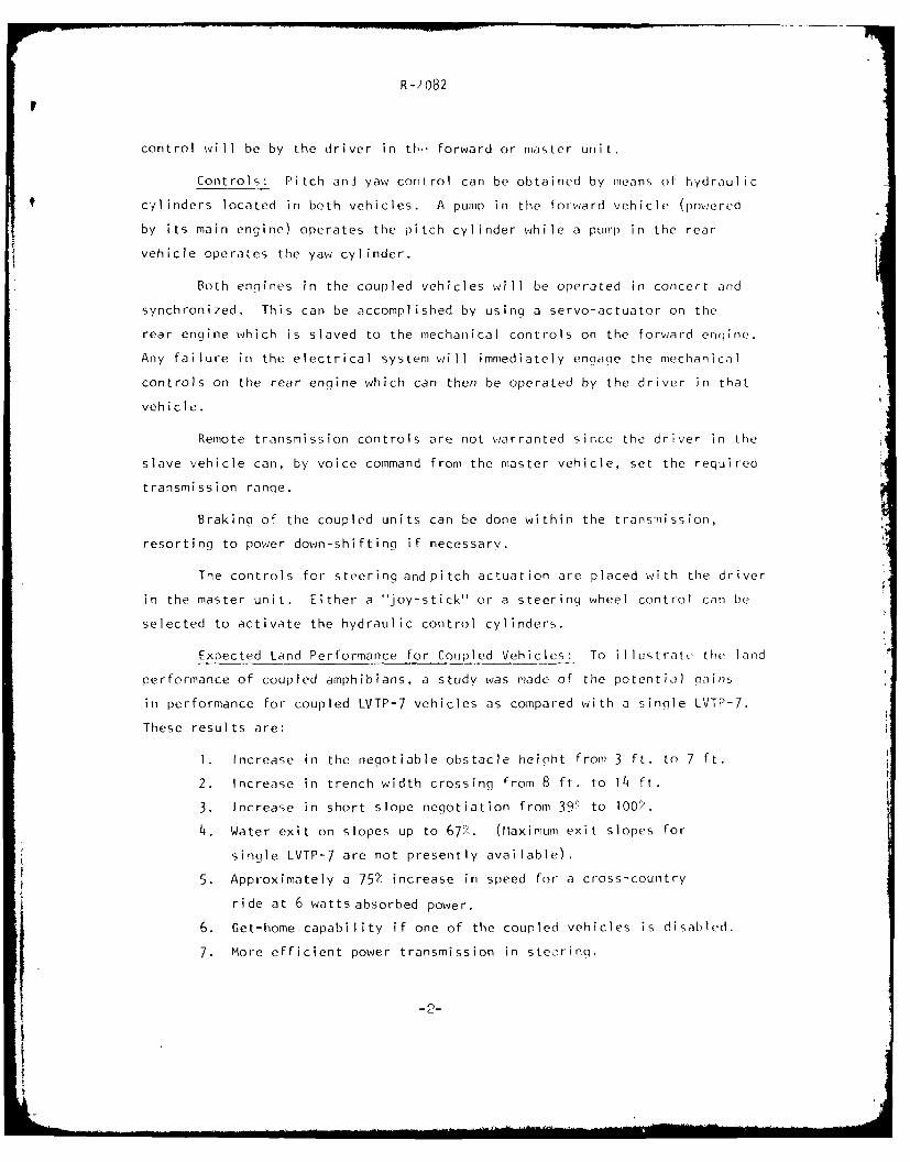
Controls: Pitch anJ yaw control can be obtained by means of hydraulic
cylinders located in both vehicles. A pump in the forward vehicle (powered
by its main engine) operates the pitch cylinder while a pump in the rear
vehicle operates the yaw cylinder.
Both engines in the coupled vehicles will be operated in concert and
synchronized. This can be accomplished by using a servo-actuator on the
rear engine which is slaved to the mechanical controls on the forward engine.
Any failure in the electrical system will immediately engage the mechanical
controls on the rear engine which can then be operated by the driver in that
vehicle.
Remote transmission controls are not warranted since the driver in the
slave vehicle can, by voice command from the master vehicle, set the required
transmission ranqe.
Braking of the coupled units can be done within the transmission,
resorting to power down-shifting if necessary.
The controls for steering andpitch actuation are placed with the driver
in the master unit. Either a ''joy-stick'' or a steering wheel control can be
selected to activate the hydraulic control cylinders.
Expected Land Performance for Coupled Vehicles: To illustrate the land
performance of coupled amphibians, a study was made of the potential gains
in performance for coupled LVTP-7 vehicles as compared with a single LVTP-7.
These results are:
1. Increase in the negotiable obstacle height from 3 ft. to 7 ft.
2. Increase in trench width crossing from 8 ft. to 14 ft.
3. Increase in short slope negotiation from 39> to OO'.
4. Water exit on slopes up to 6P,. (Maximum exit slopes for
single LVTP-7 are not presently available).
5. Approximately a 75 increase in speed for a cross-country
ride at 6 watts absorbed power.
j 6. Get-home capability if one of the coupled vehicles is disabled.
7. More efficient power transmission in steering.
-2-

R-., )82
8. Better performance and steerina in marginal terrain.
Some of the disadvantages as ociated with couplinq are listed
below:
1. Larger turning radius (no pivot turns).
2. Increased target size.
3. Additional hardware and controls results in an increase in:
weiqht
internal occupied space
cost
maintenance and driver training
Expected Water Performance for Coupled Vehicles: Compared to a
single LVTP-7, it is expected that the following gains in water performance
will be achieved by coupling the forward vehicle to have a 150 pitch in-
cidence relative to the rear vehicle.
1. The calm water drag of the coupled vehicle, on a per ton basis,
is 75% that of a single vehicle.
2. There is substantial nose-diving of a single vehicle at speeds
in excess of approximately 7 mph. The coupled vehicle shows
a continuous increase in bow trim with speeds in excess of
7 mph with no tendency to bury the bow at intermediate speeds.
3. Since coupled vehicles reduce the calm-water drag and eliminate
bow burying, speed improvements of nearly 4 mph are possible
depending upon the installed power. Such speed improvement could
not be obtained with the existing LVTP-7, no matter what the power,
because of extensive water over the bow.
4. In head seas of 2.2 ft., significant wave height (Sea State 2),
the coupled vehicle can operate at 10 mph whereas the single
vehicle is limited to speeds of about 6 mph.
5. The acceleration of the coupled vehicles in Sea State 2 attains
their maximum values at a speed of 8 mph. The RMS acceleration
is only 0.08g and the average of the 1/10-highest peak acceleration
is 0.2q at the C.G. of the forward vehicle. The accelerations in
-3-

R-2 082
the single and coupled vi'hicles are similar, but the pitch
motions of the coupled velhicles are nearly 50/ less in the
4 to 6 mph speed range.
6. Either confiquration has accelerations well below the one-hour
exposure 'fatigue decreased proficiency" limit recommended by
the International Standards Organization, and both are below
even the ISO two-hour exposure limit.
Performance of Articulated Vehicles: The articulated vehicle is a
multi-unit vehicle which is designed to operate in unison at all times and
under all conditions. A viable concept which has been developed in this
study consists of a forward section containing the main power plant and
transmission and, possibly, also containing automatic armament and ammunition.
The rear unit contains all personnel, including the driver, and an auxiliary
engine. The articulation joint with powered pitch and yaw articulation
and freedom in roll is contained in a sealed enclosure. The overall length
of the vehicle is 33 ft. (14 ft. forward section and 19 ft. aft section),
the gross weight is estimated to be 54,000 lbs. and there is only one main
engine of 890 GHP which is controlled by the driver. Steering and pitch
control are by either joy-stick or steering wheel directly to the hydraulics
actuating the joint.
The expected performance of an articulated vehicle, compared to a
single LVTP-7, is:
1. Step obstacle height of 4 ft. compared to 3 ft.
2. Trench width crossing of 14 ft. compared to 8 ft.
3. Negotiates a 58 short slope in soft soil compared to 39Z
for a single vehicle.
4. Can water exit on a slope of 67%.
5. Cross-country speed increased nearly 75% for 6-watt ride.
6. Turning radius 33 ft. compared to 15 ft. for single vehicle.
7. Since model tests were not performed, estimates of the water
performance are not available, although they are expected to
substantially exceed those of a single LVTP-7.
-4-

2.1 CONCLUSIONS
Based on the results of the present study, it is concluded that
either coupled or articulated amphibious assault landinq vehicles are
feasible and can easily be adapted to existing landing craft and/or new
designs. The expected improvement in land and water-borne performance
are impressive and are judged to outweigh those disadvantages associated
with coupled units.
2.2 RECOMMENDATIONS
Design, fabricate, and install a suitable coupling system which will
allow a bow-to-stern attachment of two LVTP-7 (or LVTPX-12) vehicles.
Conduct tests on land, in water, and in surf to demonstrate the
expected advantages of coupling and to provide operational evaluation and
experience related to coupled amphibious vehicles.
-5-

3.1 INTRODUCTION
The Davidson Laboratory of Stevens Institute of Technology has
been requested by DTNSRDC, Code 112, to explore the feasibility and
gains in performance that can be made by coupling and articulating
future Marine Corps Landing Vehicles. This is the first step towards
the short range goal which is to demonstrate the added capabilities
(and to measure such performance) with a test vehicle assembled from
two contemporary vehicles. The longer range goal is to apply the
practical and analytic knowledge gained to future vehicles to be
developed by the Marine Corps.
3.2 BACKGROUND
The coupling of pairs of vehicles has long been recognized as
a means of improving their cross-country (off-road) mobility (Reference 1).
Reasons for this improvement in performance include the improved ability
of the coupled vehicles to conform to the terrain, the inter-vehicle
assist provided by active couplina and, for tracked vehicles, reduction
in steering losses. Coupled vehicles have found acceptance where
there has been a need for superior surface mobility by both commercial
users (e.g., the "Muskox" and "Nodwell" vehicles used by oil companies
in exploring isolated parts of Canada and on the Alaskan North Slope)
and the military (e.g., the articulated tracked Snow Vehicle "BV 202"
used by the Swedish Army, the U. S. Army M-561 and the Pole-Cats used
on the Greenland Ice Cap).
The ability of coupled and articulated vehicles to negotiate
terrain impassable to a comparable single vehicle has also been demon-
strated by such prototype systems as the US/Canadian XM-571, the "Jeep
Train" built for TRECOM, the MEXA Vehicles built for the U. S. Army,
the "Twister" designed by Lockheed, and others. The additional
improvement in mobility which can be achieved by articulated vehicles
with active control of the pitch articulation has been demonstrated
in experiments with the three-unit 'Cobra" built by WNRE for the
Land Locomotion Laboratory of the U. S. Army. Table I is a short
historical overview of the characteristics of the more pertinent
articulated vehicles.

R-2 082
The most recent research effort in the area of actively coupled
vehicles was the Cybernetically Coupled Research Vehicle (CCRV) program
(Reference 5). In this program, Iwo existing tracked military vehicles
were coupled with powered articulation which was controlled in pitch
and yaw by a single joy stick incorporating force feedback. The
vehicles used were M-113-Al Armored Personnel Carriers, selected to
demonstrate the feasibility of retrofitting this special-purpose system
onto existing hardware and to allow a direct comparison of the per-
formance of a single unit with that of the coupled system. The CCRV
was shown to be superior to the single M-113 in cross country ride,
soft soil maneuverability and water speed, and far superior in vertical
obstacle negotiation, trench crossing ability, and water egress capa-
b iIi ty.
Much of the knowledge and experience gained with this vehicle
can now be applied directly to tracked amphibious landing craft. How-
ever, the prior studies centered on performance on land, so little
data is available on the effects of articulation in water. It is
the purpose of this study to explore the operational feasibility of
coupling two standard U. S. M~arine Corps amphibious tracked
landing vehicles and to validate techniques to predict the expected
performance of future coupled or articulated vehicles operating on
land and in water.
3.3 OBJECTIVES
The objectives of this program are:
1. Explore, by use of scale models, the gains that can be
made in water performance by vehicle coupling.
2. Estimate the land performance of coupled vehicles using
an extension of existing analysis methods and comparisons
with known vehicles.

R -7082
3. Develop coupling concepts which are suitable for the
U.S. Marine Corps miss ion which can both be demon-
strated for the near termn and be compatible with
contemplated future vehicle developments.
4. Investigate two groups of concept: that of vehicles
which primarily operate as single vehicles but can
be coupled when necessary and that of a multi-unit,
arrangement which always operates as a single
articulated vehicle.

4. CONSTRAINTS AND ASSUMPTIONS
The preservation of the existing operational capabilities of the
vehicles impose certain constrainLs on the coupling systems. In addi-
tion, there are assumptions that can be made based on the expected use
of the coupled vehicle. These constraints and assumptions are not
necessarily the same for both the coupled and the articulated concepts.
For the purpose of this study, the term "Coupled Vehicles" means
two or more individual vehicles which are optimized for operation as
single units but can be coupled together when operational conditions
or mobility requirements dictate it. By contrast, an "Articulated
Vehicle" is one designed to operate as one multi-unit vehicle at all
times under all conditions; it should only be broken apart for ease
of transport, for marriage with another mate of different capabilities
(wreckers, cargo carriers, tankers, etc.) or for survival when the
other unit has been catastrophically disabled.
The constraints and assumptions used in the development of the
concept will be:
For the Coupled Vehicles:
I. Preserve the rear ramp and emergency exits.
2. Preserve the cargo hatch.
3. Be able to uncouple both on land and on water.
4. Assume there will be a co-driver/monitor in the
slave unit.
5. Equip all vehicles identically so that they can beeither a front or a rear unit, interchangeably.
6. Preserve individual vehicle capabilities unimpaired.
For the Articulated Vehicle:
1. Do not exceed 33 ft in overall length.
2. Have an exit ramp for the troop compartment.
3. Have a top cargo hatch for the troop compartment.
-9-

R-: )d2
4. Have an emergency disconnect capability, with either
unit capable of limited individual operation. i
5. Have only one driver.
[-
- 0-

R -.' 182
5.1 CONCEPT DESIGN AND ANALYSIS
The investigation started with the layout of a series of general
concept ideas for the coupling of individual vehicles. The seemingly .arduous development of the concepts served the purpose of providing the
necessary basic configurations and information as input to the hydrodynarnic
scale model test program, to the land performance evaluation and to the
comparison with known vehicles. These concepts progressed from the
simplest coupling arrangement with limited capabilities to the wiore
complex, as the detailed requirements became more clearly defined. The
progression of the coupled concepts is shown in Figures 1 through 12.
The feedback from model experiments and mobility analysis placed emphasis
on the later concept versions, in order to realize the full potential
of the improvements possible in both land and water performance. Using
the primary evaluation factors in Table 11 discussed below, concept #1l2,
shown in Figure 12, was selected as the one which best combines most of
the desirable features with minimum complexity, space, weight and cost.
The primary factors used in the evaluation of each concept layout
are listed in Table 11. They are based on the following arguments:
RANGE OF MlOTION: Experience with existing coupled and articulated
vehicles, and the results of the model studies, show that the
following degrees of freedom in the joint are necessary to
perform the required functions of the vehicle.
Yaw articulation control is necessary for vehicle directional
control. In its simplest form it is the type of steering
that almost all front end loaders use. The military Goer
vehicles are also an example of simple yaw steering. Yaw
articulation of multi-unit tracked vehicles permits the
use of an effectively long vehicle (desirable for mobility)
which can still be steered. Tracked single-fraie vehicles
which have a ground contact length to tread spacing (LIT)
ratio in excess of about 2 to 1 are impossible to steer.
It is expected that yaw control will also be beneficial
in steering the craft in the water-borne mode.

R -2 82
Pitch articulation freedom is ,,ecessary for the individual units to
be able to conform to utidulations in terrain and to negotiate
obstacles. Controlling pitch attitude by powered articulation
permits the crossing of obstacles not otherwise possible, and
produces all the advantages of a long vehicle for ditch crossing
and cross country ride. In the water-borne mode, pitch articula-
tion is most beneficial in reducing hydrodynamic drag and
improving visibility.
Roll freedom is necessary to distribute the ground pressure under the
suspension elements relatively evenly. Experience shows no need
for this motion to be powered and controlled. In the water-borne
moderoll freedom allows the coupled system easily to adjust to t
the irregular wave forms, particularly in oblique seas.
POWER SUPPLY: The power for the articulation should be generated by the
engine of the vehicle on which the joint actuation hardware is
mounted, in order to minimize power transmission problems.
Hydraulic or electric systems and their combinations with mechanical
components are all possible candidates for transmission of power.
Should the coupling be configured such that each vehicle carries
part of the system then each vehicle will power that component
which it carries.
CONTROLS: The preferred location for the control station is in the forward
vehicle, for best visibility. For certain operations the control
from the rear may be of advantage, as when coupling the vehicles.
Transmission of the control command and feedback signals from
one vehicle to the other involves only the risk of the electrical
inter-vehicle signal connection. All controls must be fail-safe
to prevent run-away vehicles and in the sense that limited, or
manually controlled, operation is still possible if the inter-
connect system fails.
REMOTE COUPLING AND UNCOUPLING: This is considered to be an essential
requirement for a combat vehicle. Coupled vehicles are intended
to operate primarily as a single vehicle and should be coupled
-12-

only when the operational requirement dictates it. Subsequently,
they are to be uncoupled again and operate as single vehicles.
Any coupling concept that requires the manual assistance for
coupling or uncoupling from outside of the vehicle is considered
to be unacceptable.
INTERFERENCES WITH EXISTING VEHICLE FEATURES: Vehicle features essential
for its mission should not be interfered with. Such features
include the stern ramp, cargo hatches, personnel exits, and
armament. Its mobility as a single unit, its propulsion elements,
angles of approach and departure, ground clearance and pivot turn
clearance should not be compromised.
SPECIAL STRUCTURE REQUIRED: Special vehicle structure other than that of
the coupling joint itself, will be necessary in the adaptation of
an existing vehicle. This probably would not be necessary in the
development of a new vehicle with coupling in mind at the start
of the design.
GRAITVATION COMPONENTS: The best location for the yaw axis and that for
the pitch axis do not coincide. For the best steering efficiency,
the yaw axis should be at the midpoint between the geometric
center of the tracks of the front and rear units (this is usual~ly
also close to the midpoint between the two centers of gravity).
For best obstacle crossing capability, the pitch axis should be
as close to the leading unit as possible in order to produce the
maximum possible pitch-up attitude of the leading unit for a
given inter-vehicle pitch angle.
FORCE LIMITATION addresses the possibility that a coupling concept may
be limited in the force that can be transmitted by the joint by
reason of its inherent design, not because of the size chosen.
WEIGHT DISTRIBUTION: The added weiaht of the coupling system and its
location on the vehicle will affect the weight distribution.
Excess weight in the bow produces undesirable effects in the
hydrodynamic performance of the single vehicle. A large unbalance
in either the front or rear, will make coupling difficult, if not
impossible in water.
-13-

R-20982
VULNERABILITY pertains to the -dded components and their assemblies.
Exposed components are 'hbviously less desirable than a location
which is protected within the hull.
5.1.1 Coupled Vehicles
Concept I does not provide any powered articulation, it simply
couples the vehicles such as to allow an inter-vehicle assist.
Concepts 2 and 3 provide powered yaw articulation only, with a
2 and 3 point connection not suitable for remote coupling.
Concepts 4 and 5 provide powered yaw and pitch control, with
a three point connection. Concept 4 has independent yaw and pitch,
in concept 5 the two cylinders provide both pitch and yaw, if they
are contracted and extended in unison the vehicles pitch, if one is
contracted while the other is extended the vehicles steer. Combinations
of yaw and pitch are possible within the limits of the geometry.
Concept 6 is based on the same layout as Concept 5 but has a
mounting frame added so that the vehicles can be coupled remotely.
Concept 7 is an attempt to provide yaw articulation at a minimium
effort. Since there is no roll freedom it is doubtful that the hardware
could survive the stresses induced by the roll-motion between vehicles.
Concept 8 provides for pitch control only, yaw control is provided
by track steering. This system is of advantaqe only for simple obstacle
crossing and for pitch attitude control to improve hydrodynamic performance.
Concept 9 utilizes an off-the-shelf turntable assembly normally
used for cranes and backhoes for the yaw articulation joint. It is cheap,
relatively light, can be driven by electromechanical means, and distributes
the load on the vehicle. Pitch articulation is effected with a separate
cylinder. The coupler, of conical shape for ease of connecting, provides
the roll freedom. This arrangement is not yet optimum for remote coupling
because the fixed receptacle is on the rear unit and the moveable parts
are attached to the forward unit. Because the driver of the rear unit has
the visibility to do the coupling-up, he would need to communicate to the
driver in the forward unit how to make the position adjustments with the
R -?082
cone to match-up with the sockel.
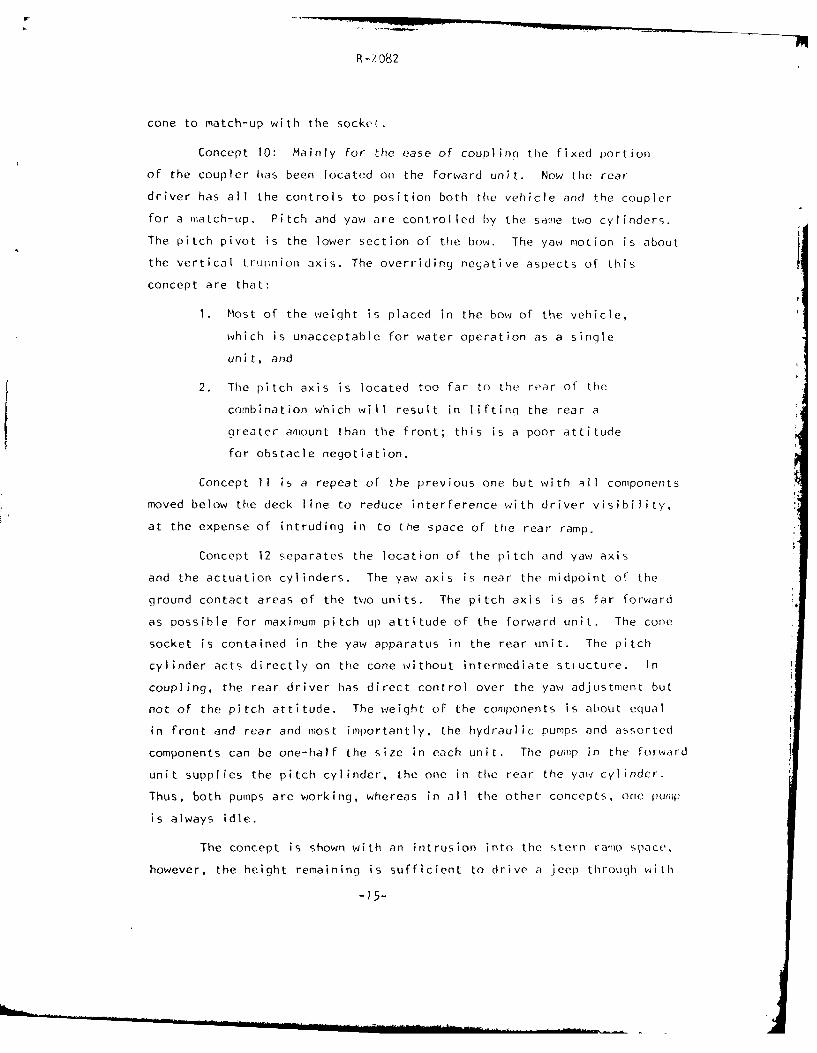
Concept 10: Mainly for the ease of couplinq the fixed portion
of the coupler has been located on the forward unit. Now the rear
driver has all the controls to position both the vehicle and the coupler
for a match-up. Pitch and yaw are controlled by the same two cylinders.
The pitch pivot is the lower section of the bow. The yaw motion is about
the vertical trunnion axis. The overriding negative aspects of this
concept are that:
1. Most of the weight is placed in the bow of the vehicle,
which is unacceptable for water operation as a single
unit, and
2. The pitch axis is located too far to the rear of the
combination which will result in lifting the rear a
greater amount than the front; this is a poor attitude
for obstacle negotiation.
Concept 11 is a repeat of the previous one but with all components
moved below the deck line to reduce interference with driver visibility,
at the expense of intruding in to the space of the rear ramp.
Concept 12 separates the location of the pitch and yaw axis
and the actuation cylinders. The yaw axis is near the midpoint of the
ground contact areas of the two units. The pitch axis is as far forward
as possible for maximum pitch up attitude of the forward unit. The cone
socket is contained in the yaw apparatus in the rear unit. The pitch
cylinder acts directly on the cone without intermediate stiucture. In
coupling, the rear driver has direct control over the yaw adjustment but
not of the pitch attitude. The weight of the components is about equal
in front and rear and most importantly, the hydraulic pumps and assorted
components can be one-half the size in each unit. The pump in the forward
unit supplies the pitch cylinder, the one in the rear the yaw cylinder.
Thus, both pumps are working, whereas in all the other concepts, one pump
is always idle.
The concept is shown with an intrusion into the stern ramp space,
however, the height remaining is sufficient to drive a jeep through with
-15-

R- 082
the windshield lowered. The wl1 o1e assembly can also be moved upward
with a concommittant compromis- in driver visibility.
All features considered, this concept combines the most attractive
features, especially those of minimum system weiqht, power sharing of the
two units, and optiiwil location of the pitch axis and yaw axis. It is
therefore, considered a prime candidate for further consideration. The
coupler is shown in detail in Section 5.1.3.
5.1.2 Articulated Vehicles
As the study progressed, it was expanded to include an arti-
culated vehicle.
By definition, this is a multi-unit vehicle which i- desiqned
to operated in unison at all times, and under all conditions, it is only
to be broken apart for transport or conceivably when a power unit is
used in conjunction with special purpose working units. One very useful
exception for a tactical vehicle may be the ability to jettison a disabled
power unit and for the troop section to be able to reach cover under its
own power.
Only one viable concept, with some minor variations, met all the
constraints imposed on the design. It is shown as Concept 13. As
depicted in Figure 13, it consists of a forward section containinq the
main power plant and transmission, possibly also automatic armament
and ammunition. The rear section contains all personnel, includinq the
driver, and the auxiliary engine.
Its tentative main characteristics are:
length, overall 33 ft
length, forward section 14 ft
lenqth, rear section 19 ft
curb weiqht 54,000 lbs
weight, forward section 15,200 lbs
weight, rear section 38,800 lbs
qround contact pressure 6 psi
turning radius, vehicleclearance (wall to wall) 35 ft
-16-

R-?982
The articulation joint with powered pitch and yaw, and roll
freedom is contained in a sealed enclosure. The driveline passes
through its center. The joint can be similar to one widely employed
in contemporary articulated vehicles and schematically shown in Figure 14.
The heavy load bearing structure is concentrated on either end of the
joint. The track and suspension are simplified because the articulation
permits variable geometry, especially of the angle of approach.
A conceptual powertrain is laid out in Figlure 15, principally
for the performance evaluation of Section 6.1. The 890 GHP main engine
is coupled to a twin shaft powershift transmission. One shaft 'oes to
the lead unit differential, the other through the articulation joints to
the rear differential. Both differentials are open so that the speed
of each track is free to conform to its turning radius, since steering
is done by yaw articulation, with each track supplying the full tractive
effort. The final drives for the front and rear unit are directly
flanged to the joint structure for minimum weight.
The rear unit, which contains the troop compartment, has its own
100 HP auxiliary powerplant. This engine supplies the hydraulic power
for steering and pitch control when articulated, and also to the two
hydraulic motors in the rear section final drive when the troop section
has to be self propelled. In addition, the auxiliary power plant
supplies air conditioning and ventilation for CBR operation, and heat,
electric and hydraulic iower for stand-by use.
The water jets are driven mechanically from a power take off
between main engine and transmission so that the tracks can be selectively
disengaged. This places the water jets in the forward section which is
less efficient than in the rear, but is offset by the weight savings in
the driveline. Deflectors behind the water jets will move in conjunction
with yaw articulation for optimum steerinq effort. Figure 16 shows the
concept in the calculated floating attitude, additional bow up pitch
attitude can be used for bow wave depression. It is recommended that
hydrodynamic model tests be performed, to evaluate the water-borne
oerformance of this unique concept.
-17-

R -:'082
The controls of the main engine and transmission, and conversely
that of yaw and pitch, are eitl,-r direct or remote depending on the
location of the driver. The preferred location of the driver is in the
rear unit for survivability, but in the forward unit he would have better
visibility. Tactics, survivability and crew back-up are additional
considerations. The configuration shown in Figure 13 shows all personnel
contained in the rear unit.N
The articulated vehicle can have three modes of operation:
1. Normal propulsion of both sections from the main engine,
auxiliary power from the small engine in the rear unit.
2. Get home capability while experiencing a main powertrain failure;
both units are connected and steered by articulation, the propulsive
power is supplied by the auxiliary engine.
3. Emergency -- the forward unit is disabled and jettisoned; the rear
unit with troop compartment is driven as a single track steered
unit using the power from the auxiliary engine via hydraulic
motors to each track.
The levels of performance that can be achieved in these three modes are
presented and discussed in Section 6.1.2.
5.1.3 Quick Disconnect Coupling
A. number of quick disconnect couplings were investigated during
the progression of the coupled vehicle concepts. As Concept 12 emerged
as the most advantageous combination, the exact design details for
the coupling joint could also be defined better. Figure 17 shows the
layout of the quick coupling joint as it is used schematically in
Concept 12. The principal size and weight calculations are included
as Appendix A. The cone, its support to the pitch joint, and the pitch
hydraulic cylinder are attached to the stern of the forward unit. The
socket, the yaw joint and the yaw cylinder are mounted in the bow of the
rear unit. The cone is free to rotate in its socket to provide the
freedom in roll. The joint, as laid out in Concept 12, provides for 300
pitch-up, 30 0 pitch-down and ±30 0 in yaw. The force exerted by the pitch
-18-I

R.-2082
actuator is directly applied between the vehicle structure and the
cone structure. The yaw pivot is directly attached to the socket.
The quick connect and disconnect function is performed by the series
of balls arranged circumferentially to engage in the groove in the cone.
The locking sleeve keeps the balls locked into the groove in the position
shown. When the sleeve is slipped forward, the balls are free to dis-
engage the cone. The locking sleeve is remotely actuated. Electrical
(or fiber optics) connection for signal transmission and communications
is made by a concentric ring connector in the tip of the cone.
The funnel shape of the cone allows for some misalignment during
coupling. A similar cone shape connector was successfully used on Jeep
Tra in I I. The Outside diameter of the cone is 20 inches based on the
extremely severe static loading conditions shown in Appendix A.
Dynamic loads, will be limited, to correspond to these loadings, by use
of proper hydraulic relief valujes. Should it be found desirable to use
the coupling concept for water operation only; this diameter can be
reduced to 14 inches.
5.2 CONTROLS
5.2.1 Background Experience
Contemporary articulated vehicles are all powered by a single
engine and transmission located in one of the units (Ref. 1). Generally
the engine is located in the same unit as the driver, thus, no special
control is needed. Power is usually transmitted mechanically to the
multiple elements via a mechanical drive line. Thus, the manipulation
of engine and transmission controls is no different than in a single
vehicle. Braking is usually done on the drive line. In the cases where
the engine is in another unit, simple remote actuators are all that is
needed.
However, in the case where individually powered vehicles are
coupled together and their combined power output is utilized, it
becomes necessary to perform all driver functions from one control
station. Coupled rail-cars, powered trailers for heavy equipment,
earthmovers, etc., are civilian examples of multi-engine ap~plications.

R-2 1)82
The military experimented with ,iulti-element vehicle trains in the 1960's,
when several large ones were built using the locomotive concept with a
single power source for the train. Another approach subsequently taken
was to utilize individually powered units which could be used as a train
or as single units. Stevens Institute investigated this concept by
building two trains comprised of fcur jeeps, considered scaled 'odels of
larger units. The first jeep train was a proof-of-concept exploratory
unit, (Ref. 2), the second a demonstrator of operational capability (Ref.3).
It was expected that the mobility of the train would exceed that of
single units because of the assistance possible between units. But
mathematical analysis and analog computer simulations showed that in-
stabilities could arise from a mismatch of tractive effort in operations
in difficult off-road terrain. Thus in the course of the design of the
first jeep train, an electro-mechanical engine control system was designed
which would allow the exploration of several modes.
The train was equipped with torque converter-automatic transmissions
and an electro-mechanical engine control system which permitted the testing
with simple throttle position control, engine speed control, drawbar force
control or force and position modulated engine control. All brakes were
centrally controlled and actuated by air. The train was fully instru-
mented to permit its evaluation in comparison to the analysis.
In over 300 tests involving all types of terrain and operational
situations it was conclusively proven that none of the highly sophisticated
control systems alleviated all of the less desirable tendencies of the
train, and that driver reactions and reliability favored the simple throttle
position control.
A second generationfour-unit train using a simple master-slave
pneumatic throttle control system was subsequently built as a demonstrator
of operational capability. Any one unit could be a lead unit, only one
driver was required. Each vehicle was equipped with a simple pneumatic
throttle actuator, a torque converter-automatic transmission and pneumatically
actuated brakes. The engine load was synchronized by adjusting all actuators
to the same engine rpm at full throttle against the load of the torque
-20-

R -082
converter at stall. Transmission range to be used was manually
selected before getting undeiway. This train proved in many
demonstrations that the simple master/slave system was successful in
synchronizing the output from all four vehicles in all types, on-and
off-road operation, ranging from extremely slippery terrain to severe
hill climbing and (relatively) high speeds on roads. By being simple
the system also proved to be very reliable.
The experience gained with the controls of the Jeep Train
was then applied to the CCRV (Ref. 4). This vehicle consists of
two standard M-113-Al APC's coupled by a powered pitch and yaw
controlled articulation joint. The purpose was to investigate the
increase possible in mobility and obstacle crossing including the
use of force feedback from the joint to the driver. Each engine was
equipped to be remotely actuated by an electro-mechanical positional
servo, actuating the governor controlled fuel injection pump. The
master unit used its mechanical linkage for actuation. Its position
was signaled to the slave which followed to the same position. The
transmission selector was actuated using the same principle: the
master retained its mechanical linkage; the slave followed by servo.
Both controls were fail-safe so that the engine returned to idle and
the transmission to low-low in case of electrical failure. The enqines
were started individually but could be stopped remotely. Again, in
case of control failure, the slave engine would shut down. Signals
for low oil pressure, no charge, and high temperature in the remote
engine were transmitted to the master control station. The driver
station could be switched from the first to the second unit, hence
the need for remote actuators in each unit.
Deceleration was accomplished by downshifting while underway,
and final stopping by using the brakes of the master unit only. This
arrangement although normally satisfactory, proved to be insufficient
to come to a full stop on very steep downgrades.
Engine load was synchronized by matching engine rpm, at each
position, against the stalled torque converter load. The transmission
-21-

R-282
selector was matched to each of the positions. The coupling system was
actuated by hydraulic cylinders and controlled electronically, which
permitted several variations in control strategy, ard positional and
force feedback.
Control of the articulation motion was done by a simple joy
stick; fore and aft movement provided pitch down and pitch up motion
respectively; side movement produced the appropriate steering motion.
Diagonal motions resulted in any combined pitch and yaw movement
possible within the constraints of joint geometry. This system used
positional control; that is, the vehicle attitude was proportional
to the position of the control stick (such as in the steering of a
car), in contrast to standard hydraulic systems which are flow controlled,
such that the motion continues as long as the signal exists. The
positional system proves to be highly successful and very natural
to operate.
One of the main objectives of this venture was the investigation
of the benefits of a force feedback system in which a proportion of
the intervehicle pitching force was transmitted to the control stick.
This feature provided the driver with a feel of the progress of the
vehicle over an obstacle and was to compensate for the lack of
visibility. Driver reaction to this feature was mixed and its merits
were never clearly established. General-cross country operation war
judged to be just as easy to handle without the force feedback system.
In as much as the coupled vehicles under consideration here
can be considered a direct descendant of the CCRV, it is natural that
its controls should be based directly on the earlier experience.
Notable exceptions, in the interest of simplicity and reliability,
will be:
1. Intervehicle force feedback to the driver will not be used
2. Transmission range selection can be done manually by the
co-driver (in the other vehicle)
3. Vehicle braking to a stand still will be done with the
help of the co-driver.
-22-

R -2 082
4. Engine start-up and shut down, as well as engine
monitoring and other auxiliary functions, can
be performed by the co-driver.
It is therefore recommended that the following controls be
cons idered as the case may apply to either the coupled or articulated
vehicle system.
5.2.2. Engine Control
Coupled Vehicles
adteIn any set of two vehicles coupled together, one will be master
adteother the slave. The driver is located in the master unit; the
extra driver in the slave unit. It is imperative for proper operation
of the coupled vehicles that both engines be operated in concert,
and synchronized. The engine control of the master unit will be actuated
with the standard mechanical linkage. A position pick-up (such as a
potentiometer) transmits that position to a servo-actuator on the slave
unit. This actuation will position the slaved control until the error
signal is removed, i.e., its position is identical to that of the master
un it.
The polarity of the system has to be such that the rack position
goes to idle if there is a failure in the signal line. In the absence
of an electrical signal, the engine of the slave vehicle is controlled
by its mechanical linkage, just as during operation as a single unit.
Articulated Vehicles
There will be only one main engine which will be controlled either
diectly, or remotely, by the driver. The auxiliary engine is envisioned
for emergency propulsion only, not in conjunction with the main engine.
therefore there is no need for a master/slave arrangement.
5.2.3 Transmission Range Selection
Since there is to be a driver in the slave vehcle, remote trans-
mission controls are not warranted. Transmission iange can be selected
manually on voice command. The articulated vehicle has only one transmission.
-23-

R-'8 2
5.2.4 Brakes
Because it is anticipated that the vehicle will be coupled only
under difficult off-road conditions where the rolling resistance is high,
the braking of the combination is done within the transmission, resorting
to power down shifting if necessary. The braking to a standstill can
be done by voice command to the co-driver.
5.2.5 Steering in Pitch and Yaw
Coupled Vehicles:
The controls for steering and pitch actuation must be placed
with the driver in the master unit. The joy-stick control of CCRV was
highly successful; it was the best approach for a vehicle equipped with
brake laterals. However, for vehicles equipped with a steering wheel,
the ,,aw control may be incorporated into the natural steering motion
via an electrical command signal. Depending on the steering characteristics
of the transmission it may be necessary to coordinate the joint steering
command with that of the transmission. The joint will be actuated hydrauli-
cally, pitch and yaw may be interrelated or separate depending on design.
The control signal will be electrical, controlling either flow control
valves or pumnp stroke. The pitch command can he built into a fore-and-aft
motion of the steering column or tilt motion of the wheel (which can be
locked out for single operation). All controls will have positional
feedback.
Articulated Vehicles
Steering and pitch control can be by either steering wheel or
joy-stick linked to the hydraulics actuating the joint. In normal
operation there is no need for interaction with the transmissionbecause of the use of open differentials. Under emergency conditions,
when the forward unit is jettisoned, the articulation joint hydraulics
will supply power to two hydraul ic motors in the final drive of the rear
unit, using the same controls. If the driver is located in the rear
unit, the main engine and transmission have to be controlled remotely
but the articulation controls are directly connected to the hydraulJics.
If the driver is in the forward unit the above is reversed, and a co-driver
-24-

R?-2182
is needed in the rear for emeruiency operation. All articulation joint
controls will have positional feedback.
5.2.6 Coupling Connect and Disconnect
Routine coupling and uncoupling applies only to the coupled
vehicle concept. Connecting the couplinq on land or in water has to beI:I
done by the driver in the rear unit, only he has the proper visibility
to perform this function. Communication during this phase has to be
by radio link since the hardwire connection does not exist until the
vehicles a -e linked up. Differences in elevation of the two mating
parts have to be adjusted by joint motion. Lateral misalignment can
be compensaLed for by steering the single (trailing) vehicle and by the
yaw articulation. This type of linking up has been done successfully
with the CCRV. Coupling under extreme attitudes, such as one vehicle
stuck in a ditch, may well not be possiblE.
Uncoupling of the vehicles will he possible at the option of
each driver and probably at just about any att;tude. The engine control
will return to the mechanical mode and to the fa;l-save position because
the command signal is lost, alerting the co-driver that he is back in
control. The pitch and yaw actuation becbmes inoperative because the
vehicles are disconnected. All other functions, having been performed
by each driver while coupled, remain the same when single.
The articulated vehicle is not intended to be easily, or routinely
coupled and uncoupled in the field. There will be a provision to
forcibly separate the units, in an emergency such as by detonating
links; once that has been done the re-joining of sections is not expected
to be a field operation.
5.2.7 kWater Steering
The CCRV, being assembled of two M-13's which have track
propulsion only, showed that the coupled units being steered by yaw
articulation only had the same maneuverability as a single unit steered
with differential track speed.
-25-

R-2082
In the case of an amphihious vehicle with separate water
propulsion devices it is expected to be of advantaqe to steer with
both yaw articulation and the propulsors. For vehicles with a
cross-drive transmission, this will not require special controls
since the yaw articulation has to be connected into the normal steering
mode, and the land and water mode steering system are interconnected
for singles operation. Coordinating the propulsors with articulation
will also prevent interference of the propulsor stream with the stern
section.
5.2.8 Miscellaneous
Coupled Vehicles
Since there is a co-driver in the slave unit, a number of
functions not critical in their exact timing can be performed by the
co-driver in communication with his master. In this category are:
1. Engine starting and stopping
2. Transmission range shifting
3. Brakeapplication to augment transmission retardation
4. Engage water propulsion
5. Observation of low oil pressure, high temperature, low voltage, etc.
6. Activate bilge pumps
7. Uncoupling or coupling
8. Overriding any automatic function when necessary.
Articulated Vehicles
If the driver is placed in the forward section, then the co-driver
in the troop section is responsible for the monitoring of the auxiliary
engine and the functions it performs. He also communicates to the driver
any observations which might affect the operation of the articulated
vehicle and which cannot be displayed to the driver.
-26-

R-)082
6. -PERFORMANCE EVALUATION
6.1 LAND PERFORMANCE
6.1.1 Tractive Effort
For a track-laying vehicle, the tractive effort versus
speed characteristic presents the maximum force available at the
sprocket from the powertrain (engine/transmission) at a given speed.
If two identical vehicles are coupled, each can produce the same
sprocket torque at a given speed so the shape of the tractive effort
versus speed curve is the same for a single vehicle or the combination,
but the coupled pair has double the tractive effort available (as
well as double the weight of a single unit) (Reference 5).
For the articulated concept, as discussed earlier, a
new powertrain was laid out (Figure 15). The tract ive effort versus
speed graph (Figure 18) for the engine and transmissioni selected
suggests that the manual transmission chosen for simplicitv is not
the optimal choice in this case. In particular, the addition of a
torque converter would increase the tractive force available at
low speeds.
6.1.2 Acceleration
The ability of a vehicle to reach a certain speed and to
cover a certain distance as a function of elapsed time from a standing
start is simulated in the acceleration analysis. The acceleration
graphs present these results for various surfaces. For this analysis,
the rolling resistance (soil motion resistance plus suspension rolling
resistance) is assumed to be a fixed percentage of gross vehicle
weight. The possible difference in soil motion resistance between
a single vehicle and a coupled pair of vehicles, discussed below
under soft soil, was not considered here.
Because of the assumipt ion that the ratio of motion res is-
tance to weight and therefore that of tract ive effort to weight, is
the same for the single and coupled vehicles, there is no difference
-21-

R -?,)82
in the acceleration of the single and the coupled vehicles with full
power. However, the coupled vehicles provide the possibility of
operation with reduced performance even if one of the units is
totally without power. To assess this capability, the acceleration
simulation was run for the coupled vehicles with both vehicles powered
and with only one vehicle of the combination powered. This simulation
was done with five values of the ratio of motion resistance to vehicle
weight and for three vehicles, the LVTP-7, the M1lB-Al and a paper
concept. The three vehicles vary in weight from 22,600 to 52,000
pounds per unit and the concept has a higher power to weight ratio.
The results are presented in Appendix B. Figures 19 and 20 show, as
an example, the comparative performance of coupled P-7's with either
one or two engines operational. In all cases, the performance remain-
ing to the coupled vehicle with one unit disabled is felt to offer a
useful operational capability.
In order to obtain comparable results for the articulated
concept further operational options have to be established: In normal
operat ion, tractive power is provided by the main engine in the front
unit. For the disabled unit performance simulation, it is postulated
that: 1) the main engine is disabled, and that all power is provided
by the 100 HP engine normally used for auxiliary power; and 2) that
the forward unit has been jettisoned and the rear unit only is propelled
by the auxiliary engine, It is further assumed that 20K ,of this power
will still be needed for other purposes and that the emergency power-
t'rain has 80, efficiency. The simulation was run only at a single
value of 90 lb/ton motion resistance since the prior analysis for the
coupled vehicles had shown no qualitative differences in the trend
with change in this parameter. The simulation was performed both
with the two-section articulated vehicle powered by the auxiliary
engine and then with only the rear (personnel) section so powered.
The results are presented in Figures 21 and 22. The degradation in
performance is, of course, considerable but the remaining operational
capacity is still significant in terms of the vehicles' survival.

R-2 182
6.1.3 Soft Soil Performance
Two soil measurement , 'stems are presently in use to assess
vehicle performance in soft soil. One is the Cone Index system, and
the other the Bekker system. Both have been developed primarily for
standard (single unit) tracked vehicles.
To use the Cone Index system, the vehicle cone index (VCI )
is first calculated for each vehicle. VCI I represents the minimum
soil strength (in rating cone index) required for the vehicle to make
one pass through the soil, i.e., if the soil strength (RCI) in a region
does not exceed VCI, the vehicle cannot operate in the region. VCI I
which is primarily a function of average ground contact pressure,
provides a general measure of gross vehicle mobility. In addition,
knowing the VCIl and the soil strength and type in a reqion, one can
calculate the rolling resistance expected in the first pass through
the region.
In the case of the coupled vehicles, this approach must
be taken cautiously. If the coupled vehicle is merely regarded as a
larger and heavier tracked vehicle, a single -jnit and a coupled pair
of identical units have the same VCI 1 Then for any soil, the cone
index system calculation will yield the same resistance to vehicle
weight ratio. However, the real situation is better %1;-wed as identi-
cal vehicles making a first and second pass through the soil. One
should calculate VCI2 (second pass vehicle cone index) for the second
vehicle and a corresponding resistance. The published data which is
the basis for the cone index relationships is primarily the result
of first pass tests. There have been some tests performed to assess
capability to traverse a region 50 times which have resulted in the
equation for VCI 50, the 50-pass vehicle cone index (i.e., the soil
strength required to permit a vehicle to pass over the soil 50 times)
but VCI has not been considered. VCI and VCI are listed in2 1 50
Table III for the single and coupled Mll3 and LVTP-7 and for the
articulated concept. All were calculated as if the multi-unit vehicles
are long single-unit vehicles.
-29-

R-<)82
In an attempt to obta;n some quantification of the dif-
ference in soil motion resistance between a single and coupled vehicle,
the Bekker soil system was used to calculate the sinkage and total
soil motion resistance in selected critical soft soils. As the Bekker
methodology accounts for the difference in compaction from the first
* and the later road wheels, the resulting resistances reflect the
fact that the second unit rides in the rut from the first unit. Oi
the selected soils, decreases in resistance to weight ratio of I0 -
20 7 were predicted for the coupled vehicles over the resistance
ratios for a single vehicle. The results are presented in Table IV.
This agrees with the Drawbar Pull Tests of the CCRV (Reference 5).
6.1.4 Obstacle Negotiation
In many terrains, the major impediment to vehicle travel
comes from the obstacles (natural or man-made) which must be negotiated
or avoided. Since going around impassable obstacles causes an increase
in travel time, improvement in capability to negotiate obstacles can
yield a significant increase in overall mobility.
Coupling vehicles is a way to obtain improved performance,
in this respect, for several reasons. The first can be regarded as a
scale effect. The coupled vehicle is, in effect, a larger vehicle
and in general, the larger the vehicle is the larger the obstacle must
be to stop it. The second reason for improvement in performance comes
from the greater ability of the coupled (or articulated) vehicle to
conform to the surface and utilize its full tractive power. A third
reason is that the intervehicle forces that are exerted will compen-
sate for those that cannot be generated by tractive effort on the
obstacle. We will now briefly examine and quantify this performance
improvement in three situations.
6.1.4.1 Step Climbing
When a tracked vehicle confronts a hard vertical
step (wall) on a hard surface, the limiting factor is the height at
which geometric interference prevents the track from contacting the
-30-
R-?")82
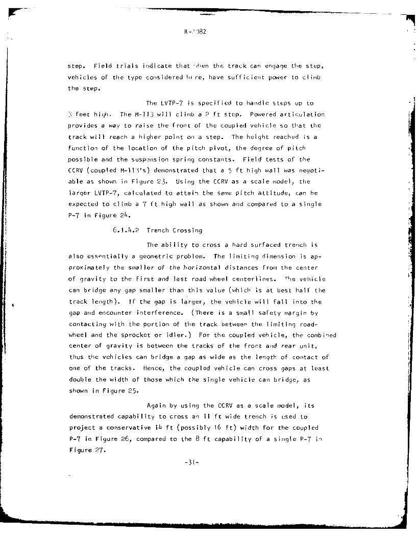
step. Field trials indicate that jhen the track can) engage the step,
vehicles of the type considered h re, have sufficient power to climb
the step.
The LVTP-7 is specified to handle steps up to
i feet high. The M-113 will climb a 2 ft step. Powered articulation
provides a way to raise the front of the coupled vehicle so that the
track will reach a higher point on a step. The height reached is a
function of the location of the pitch pivot, the degree of pitch
possible and the suspe-nsion spring constants. Field tests of the
CCRV (coupled M-113's) demonstrated that a 5 ft high wall was negoti-
able as shown in Figure 23. Using the CCRV as a scale model, the
larger LVTP-7, calculated to attain the same pitch attitude, can be
expected to climb a 7 ft high wall as shown and compared to a single
P-7 in Figure 24.
6.1.4.2 Trench Crossing
The ability to cross a hard surfaced trench is
also essentially a geometric problem. The limiting dimension is ap-
proximately the smaller of the horizontal distances from the center
of gravity to the first and last road wheel centerlines. The vehicle
can bridge any gap smaller than this value (which is at best half the
track length). If the gap is larger, the vehicle will fall into the
gap and encounter interference. (There is a small safety margin by
contacting with the portion of the track between the limiting road-
wheel and the sprocket or idler.) For the coupled vehicle, the combined
center of gravity is between the tracks of the front and rear unit,
thus the vehicles can bridge a gap as wide as the length of contact of
one of the tracks. Hence, the coupled vehicle can cross gaps at least
double the width of those which the single vehicle can bridge, as
shown in Figure 25.
Again by using the CCRV as a scale model, its
demonstrated capability to cross an 11 ft wide trench is used to
project a conservative 14 ft (possibly 16 ft) width for the coupled
P-7 in Figure 26, compared to the 8 ft capability of a single P-7 in
Figure 27.
-31-

R -7'182
6.1.4.3 Climbing of Ilatural Terrain Feature Obstacles
A finely detailed analysis of the motions of and
forces on a vehicle during negotiation of a general obstacle (i.e.,
an obstacle having an arbitrary shape and soil) would require extension
of existing methodology. The most recently developed simulation
obstacle negotiation is that called OBS78B, which is a part of the
NATO Reference Mobility Model, Edition I completed in the Spring of
1979 (Reference 6). In this simulation, all compliance and dynamic
effects are neglected, the obstacles are symmetric trapezoids and
motion resistance is accounted for through a uniform coefficient.
The simulation only deals with single unit tracked vehicles and even
these are modeled as equivalent wheeled vehicles. A validation program
and further development of this simulation are planned. An extension
to articulated tracked vehicles is highly desirable, but some distance
in the future.
Consequently, for this study, a "quick look"
approach was taken for this obstacle negotiation problem. In the
LVA Concept Analysis (Reference 7), the Linear Features/Obstacle
Module was designed to assess the vehicle's capability at those
points in the obstacle negotiation which were judged to be the criti-
cal places. Mission scenarios typical of operational conditions which
would be encountered by this class of vehicle were defined.
Reviewing the results of thce LVA Mobility
Analysis it was observed that all of the NO-GO's identified for the
LVTP-7 had the same cause. This was a lack of sufficient tractive
force to climb the obstacle due to a combination of weak soil and
obstacle geometry (approach slope and obstacle height).
The advantage of coupled vehicles lies in the
capability of the unit which is still (or, again) on level ground to
assist the unit on the slope. If the slope is long enough for both
vehicles to be on it at the same time, there is no benefit to coupling.
-32-

R-) 82
The basic relationships for this analysis are
presented in Appendix C. The results of the analysis comparinq single
and coupled units of P-7 size on an obstacle of a height arbitrarily
chosen as 200 inches are given below:
Limiting Slope (Degrees)
SOlL TYPE f Singlei Coupled
Cohesive c = 3 psi lb.0 28.5
c = 4 psi 23.5 4-.5
Frictional p = 200 15.5 31.0
S= 25 21.5 15.0
6.1.5 Water Exiting
At the present time there is no acceptable analytical pro-
cedure available to calculate the exiting capability of vehicles, let
alone coupled or articulated ones. Therefore, the same procedure
was used as for the obstacles, that is, to compare the coupled vehi-
cles to the known performance of the CCRV of Reference 5. For that
purpose, the floating trim attitude of the coupled P-T models was
measured in the towing tank, and found to be identical to that of the
CCRV. Figure 28 shows the two vehicles in their static floating
attitude against a 340 shore slope which the CCRV was able to negotiate.
In Figure 29 it is clearly evident that the trimmed up P-7 has the
advantage of engaging the shore slope with the front approach slope
of the track, whereas, the single vehicle engages the shore with the
bow section of the hull. It is reasonable to assume that the perfor-
mance of the coupled vehicle will match that of the CCRV whose exiting
performance is known in Figure 30, as reproduced from Reference 5.
6.1.6 Corridor Turning
A computer simulation has been developed by Stevens Institute
of Technology (Reference 8) to evaluate the corridor turninq performance
of a vehicle. Both conventional tracked vehicles and vehicles steered
by articulating can be analyzed. The program simulates a vehicle turninq
in an L-Shape (perpendicular) corridor.
-33-

R -2 982
Figure 31 is a represc-itation of a conventional tracked
vehicle of length 1, and width w, traversing an L-shaped corridor
having street widths of a and b. The vehicle clearance and
minimum clearance radii as well as the path radius of the vehicle
center of gravity are calculated using the geometric fit of the
rectangular shape through the corridor. Figure 32 shows the results
for a single P-7.
The evaluation of a vehicle steered by articulation is
similar to that for the single vehicle. It is based on the geometric
relation of moving a single box shape as shown by the dotted lines
superimposed in Figure 33 through the corridor. The input parameters
are the length of the coupled vehicles, the vehicle width, and the
maximum allowable articulation angle.
An additional constraint is imposed by the geometry of
steering by articulation. Accordingly, the method for calculating
the vehicle clearance radius, the minimum clearance radius and the
corridor width as a function of yaw angle, and vehicle length and
width is shown in Figure 314. It assumes identical box-like vehicles
and a symmetrical relationship.
Some representative comparison values are:
P-7 Coupled P-7
*Vehicle clearance radius 16.5 ft 61 ft
*Minimum corridor width required 16.5 ft 27.5 ft
The limitations on vehicle turning imposed by the trans-
mission are considered next. Figure 35 shows the relationship between
vehicle speed and path radius for the LVTP-7 with the HS-tiOO trans-
mission. Note that while the vehicle can make a pivot turn, it does
such a turn in neutral at zero speed.
Figure 36 shows a combination of the transmniss ion capa-
bilities and the vehicle geometry limitations, defining the areas
of useful operation of the single and the coupled P-7's.
-34

R-:)')82
6.1.7 Cross Country Ride
Cross country veh*cle performance is limited by a variety
of factors. In soft soil, lack of power or the ability to transmit
the power to the soil may be the limiting factoi. In other places
lack of visibility or maneuvering around and among obstacles and
vegetation can be the primary factor. On relatively hard surfaces,
the limiting factor is often the driver's tolerance to his vibrational
environment when the vehicle is operating over continuously rough
ground and/or the driver's tolerance to impacts received while the
vehicle is crossing discrete obstacles. The vehicle/driver/terrain
interaction, together with the related vibrations and impacts at
other locations in the vehicle, are usually referred to as "ride".
Articulation and coupling has long been recognized as a way to
obtain a significantly better ride in tracked Vehicles (Ref. 1). This is
due to the articulated vehicle having greater length than a comparable
single vehicle as well as power absorption in the coupling. This was
also borne out by the ride evaluation test in the CCRV program, which
was condutLed over a single course having an RMS roughness of about
2 inches. Compared at the commonly used power absorption level of
6 watts in the vertical direction at the drivers' seat, the coupled
units could be driven 50 percent faster than the single unit in
rigid mode (length effect) and twice as fast in a limited pitch freedom
mode (combined length and damping effects) (see Figure 37, borrowed
from Reference 5).
Computer programs to predict ride quality exist. They are
time consuming and costly to run. The accuracy of the output is
dependent on the accuracy of input parameters whose values are usually
difficult to obtain. For these reasons, a complete ride analysis was
judged to be beyond the scope of this study.
6.1.8 Land Performance Summary
A summary comparing the known land performance of several
existing vehicles with the projected performance of the concepts is
presented in Table V.
-35-

R-2982
6.2 WATER PERFORMANCE
The behavior of the coupled LVT in calm water and head seas was
determined from sub-scale model tests using 1/8.2-scale models. This
section describes the models used, the test techniques, the results
obtained and discusses the full-scale predicted performance.
In order to give the mcdel study a degree of real ism, the tests
were based on the LVTP-7 amphibious tracked vehicle used by the Marine
Corps. It should be recogni;:ed that the characteristic behaviour of
I ( the coupled LVT is not dependent on the specific vehicle type and as
far as possible the results and conclusions are presented in a form
independent of the specific configuration. The selection of the P-7
for the purpose of making model tests was discussed with and agreed
41 to by DTNSRDC Code 112.
6.2.1 Model Description
Two models of the LVTP-7 were built and one of the pair isS
shown in Figure 38. Each model had an overall length of 38 inches (a
model scale of 1/8.2) and was built to FMC Dwg. No. 4168484. The pine
models incorporated flexible tracks, moveable suspension systems and
individual road wheels which could be adjusted to allow for track
extens ion.
The models were coupled together with a spacing between
them corresponding to 14 inches: hereafter all quantities will be
given in terms of full-size equivalents. The coupled models could be
run free-to-pitch about the main bearing located 56 inches above the
vehicle base line and midway between the two vehicles. The relative
incidence between the coupled vehicles would be fixed by means of a
pair of adjustable tie rods between the lead and trail ing vehicle
located 8.75 ft. above the base line and spaced 5 ft. apart to ,Yllow
for yaw adjustment.
-36-

R-2082
The lead model was equipped with a free-to-trim towing
fitting whose pitch axis was 170 inches aft of the bow and 51.7 inches
above the base line (STA 204 and WL 51.7). Both models had accelero-
meters located at STA 178 on the model centerline to measure the
vehicle acceleration in the rough water tests. In order to measure
the bending moment between the coupled vehicles in waves, the adjustable
coupling was replaced by a strain-gaged beam for a limited series of
tests.
Model particulars are given in Table VI.
6.2.2 Test Program
Tests were conducted in the Davidson Laboratory Tank 3 test
facility, a high speed towing tank 300 ft. in length, 12 ft. wide by
6 ft. deep, equipped with a monorail drive and plunger wave maker.
The test models were ballasted to draft marks corresponding
to the Combat Equipped LVTP-7. This loading was selected as being the
most severe because the associated forward LCG on the current LVTP-7 Al
leads to green water over the bow at intermediate speeds. Tests were
also run at the Combat Loaded Condition:
Condition Wih t lb. "'LCG STA LCG,7L
Coinbat Equipped 42,377 IQ7.8 9 49.3
Combat Loaded 52,377 199.85 53.2
Longitudinal locations on the P-7 are conventionally given
in terms of Stations which are distances aft of the bow in inche, plus
34 inches. Positions as a percentage of the overall length are obtained
by subtracting 34 and dividing by the length of 312 inches.
Tests were run with the single vehicle in calm water over
the speed range of 4 to 9 mph in order to provide correlation between
model and full-scale data. In this as in all the tests, the tracks were
extended and hung in a free catenary taken to be representative of
operating conditions.
-37-

R-2982
The models were then coupled together and a series of calm
water exploratory tests were ron to determine the effects of relative
incidence between the models, locked versus free-to-pitch coupling,
and spacing. The test conditions were selected from the following
matrixi
Load Condition Combat Equipped
Speed, mph 4,5,6,7,8,9,10,11,12,13
Relative Incidence, Deg. Free, 0,2.7,I4,5.5,7,10,15
Inter-Vehicle Spacing, In. 14, 30
Head sea tests in Sea State 2 (significant wave height
2.2 ft.) were then run for the following conditions based on the find-
ings of the calm water exploratory tests:
Load Condition Combat Equipped
Speed, mph 6 and 8
Relative Incidence, Deg. Free, 0, 1O, 15
Inter-Vehicle Spacing, In. 14
On the basis of deck wetting and driver visibility the 15
degree incidence was selected as optimum: in the static condition at
this relative incidence the coupled vehicles floated with the lead
vehiclz at a bow-up trim of 7 degrees and the trailing vehicle in a
bow-down attitdue of 8 degrees, Figure 39. The drag of the coupled
vehicles did not vary with incidence and changes in vehicle spacing
had no significant effect.
With the coupled vehicles at 15 degrees incidence and 14
inches spacing the following conditions were run in calm water and
head seas:
Loading, lb. 42,377 and 52,377
Speed, mph 4, 5, 6, 7, 8, 9, 1O, 11, 12, 13
Significant Wave Height, Ft. 2.2 and 3.3
-38-
____n"

R-7082
In addition, the effect of fitting a bow extension to the
lead vehicle was investigated. Both buoyant and non-buoyant extensions
(5 ft. by 5 ft. in planform) were tried.
6.2.3 Test Results
The measured quantities included the drag, trim and draft
of the lead vehicle in calm water. In the head sea tests these measure-
ments were supplemented by recordings of the accelerations in the lead
and trail ing vehicles at points 46X of the vehicle length behind the
bow of each vehicle.
The test results are discussed 'in the following sections
and are presented graphically in Figures 40 through 51.
In addition to these quantitative results, video tape
recordings were made of the rough water tests, the head and beam sea
coupling experiments were recorded on motion picture film, and still
photographs were taken of representative test conditions.
6.2.4 Full-Scale Predictions
6.2.4.1 Single Vehicle in Calm Water
The model results are expanded to full-scale by
a technique known as Froude Scaling in which velocities are multiplied
by 2.86 (the square-root of the 8.2 scale ratio) and forces are
multiplied by the cube of the scale and by the ratio of the density of
salt water to fresh water, which is the displacement ratio of 566. To
demonstrate the validity of this technique the results are compared
to the full-scale values obtained with the prototype LVTX-12 in Figure
40.
Although the LCG on the prototype LVTX-12 was 6.5
inches further aft than that of the LVTP-7, good agreement was obtained
between the model and full-scale results (Reference 9).
-39-

R -2082
Also showi on this plot is the thrust available
from the jet assuming an installed power loading for the P-7 of 21
Hp/ton, an allowance for auxiliaries of 17.5%~ and an overall propulsive
coefficient of 40% based on the trial results. It is clear that the
P-7 has the power to go faster if it were not for the decrease in trim
above 8 mph. The results of the prototype trials contain the obser-
vation that the speed is limited by the (negative) vehicle trim.
6.2.4.2 Coupled Vehicle in Calm Water
The calm water drag of the coupled vehicle at the
combat equipped weight is shown in Figure 41 and contrasted with that
of the single vehicle.
The relative incidence between the coupled vehicles
has no effect on the drag, so that the incidence may be selected on
the basis of running attitude and water shipped over the bow and on to
the driver's station. Variation in spacing between the vehicles also
had no effect on the drag so that this parameter may be selected to
accommodate the yaw angle necessary to steer the vehicle. The drag of
the coupled vehicle, on a per ton basis, is about 754 that of the single
vehicle due to doubling the length; above 8 mph the c:oupled vehicle
has a speed advantage of 2 mph for the same installed power, since it
does not bury its bow like the single vehicle. Thrust available from
power installations of 20 and 30 Hp/lb. are shown in Figure 41 to
show the increasing speed advantage of the coupled vehicle as the
power increases.
The increase in the running trim of the lead
vehicle as the relative incidence is increased is shown in Figure 42.
L The nose-diving of the single vehicle above 8 mph is obvious in the
trim track at the bottom of the figure. At 15 degrees incidence the
bow-up trim of the coupled vehicle increases wic~h speed with no tendency
to bury the bow at intermediate speeds. Beyond 15 degrees incidence
9: the vision blocks at the driver's station of the trail ing vehicle
-40-

R-2082
would be continually under watr. Therefore the 15 degree incidence
was identified as an appropriate attitude in which to run the main
investigation "ncluding the study of rough water behavior.
The drag of the combat loaded coupled LVT, at 15
degrees incidence, is 7. less than that of the combat equipped vehicle
as shon in Figure 4 3 . The trim of the heavier vehicle is also half
a degree higher, and therefore the bow drier, than at the combat equip-
ped load. Thus, the performance of the combat loaded coupled LVT is
better than that of the combat equipped vehicle, since the drag in
pounds per ton of the heavier vehicle is T/, less and the trim is half
a degree higher. These considerations lead to the choice of the
combat equipped vehicle as the configuration to be used in the pre-
liminary coupling experiments.
The calm water tests showed that coupl ing two LVT
together resulted in significant drag reduction, eliminated bow burying
and thereby opened the way for speed improvements of 2 to 4 mph
depending on the installed power. Speed improvements that could not
be obtained with the basic P-7 no matter what the power because of
water over the bow. These improvements in performance were obtained
with a modest relative incidence of 15 degrees and only got better
as the vehicle weight was increased from combat equipped to combat
loaded.
6.2.4.3 Seakeeping of Coupled Vehicle
The performance of the coupled LVT in head seas
of 2.2 ft. significant wave height (Sea State 2) is shown in Figure 44.
For the coupled vehic'le operation in this sea state reduces the maximum
speed by only 0.5 mph. Compared with the single vehicle in the same
sea state, however, the coupled vehicle can operate at 10 mph whereas
the single vehicle is limited to speeds of about 6 mph. The reason for
this is excessive water over the bow of the single vehicle at speeds
above 6 mph. This situation is illustrated by Figure 45 where the
-41-

R-2)82
single and coupled vehicles in Sea State 2, running at 6 and 10 mph
respectively, are shown. It may be noted that to achieve a speed of
10 mph with the coupled LVT does not require a large power installation:
in fact a power loading of 22.4 Hp/ton as in the current LVTP-7 would
be sufficient. On the other hand, no amount of installed power will
make the single vehicle go faster because of the diving tendency.
The seakeeping behavior of the coupled vehicle is
summarized in Figure 46. The RMS vertical acceleration 9 inches ahead
of the CG of the lead vehicle is shown in the upper graph as a function
of speed. The acceleration at the corresponding point in the trailing
vehicle is 40% less. The accelerations are quite modest and are seen
to reach their maximum at 8 mph where for the combat equipped lead
vehicle the RMS acceleration is 0.08g and the avetage of the 1/10
highest peak acceleration is 0.2g. Increasing the weight from combat
equipped to combat loaded decreases the accelerations and the motions
as shown in the lower plot. Increasing the speed from 6 to 10 mph
reduces the pitching and heaving motions 30%. While the accelerations
in the single and coupled vehicle are similar, the motions of the
coupled vehicle are much smaller in the 4 to 6 mph speed range.
The ride quality in Sea State 2 at 8 mph in the
combat equipped condition, where the coupled vehicle experiences the
largest accelerations, is shown in Figure 47. The lead vehicle of the
coupled LVT shows a peak RMS acceleration at 0.4 Hz that is 157, higher
than the single vehicle; however, operation of the single vehicle at
8 mph is barely practical due to bow burying. Either configuration
is well below the one hour exposure "fatigue decreased proficiency"
limit recommended by the International Standards Organization, and both
are below even the ISO two hour exposure limit.
The tests in waves showed that the coupled LVT
behaved well at speeds up to 10 mph. Above this speed in headseas,
however, considerable water was shipped over the bow. An experiment
-42-

R -2182
was conducted in which a 5 ft. bow extension was fitted as shown in
Figure 48. The non-buoyant extension was very successful in sup-
pressing the baov waves at speeds of 10 and 12 mph as shown in Figure
49. With sufficient power installed this simple bow extension, which
could !asily be folded when not in use, would extend rough water
operation to at least 12 mph. The effect on the seakeeping perfor-
mance is shown in Figure 50 for Sea States 2 and 3 (significant wave
heights of 2.2 and 3.3 ft.). The increase in drag between Sea States
2 and 3 is minor and while the acceleration in Sea State 3 is 50/
greater than in Sea State 2, the 1/10th highest acceleration in Sea
State 3 is still only 0.3g.
The possibility of coupling the two vehicles in
a seaway was examined in a qualitative manner. The uncoupled vehicles
were placed bo4-to-stern in head seas and beam seas and their resulting
motion recorded on color motion picture film. Targets and grids were
mounted on the models to assist in estimating the resulting motions.
It seems unlikely that the vehicles could be coupled in head seas due
to the excessive relative motions. Coupling in beam seas might be
possible and deserves further study if an operational need develops.
In order to determine the bending moment between
the vehicles, and consequently the size of the coupling, the rigid
coupling was replaced by a strain-gage beam that held the models at a
relative incidence of 15 degrees. The models were run in head seas of
State 2 up to 12 mph and time histories of the bending moment were
recorded and analyzed. The mean bending moment is shown in Figure 51
together with the maximum and minimum values. This data was used
to size a "water-only" coupling.
6.2.5 Hydrodynamic Performance Sumar
A summary of the hydrodynamic performance is presented in
Table VII.
-43-

R- 2982
ACKNOWLEDGEMENTS
This study was conducted under the sponsorship of the Department of
the Navy, for David Taylor Naval Ship Research and Development Center, Code 112.
The authors acknowledge the direction and useful guidance received durinq this
project from Messrs. Ed O'Neill and Ernest Wolfe of the Systems Development
Department.
Very appropriately, for an amphibious vehicle investigation, this effort
integrated the capabilities of the Transportation Research Group for the land
mobility studies, and the Marine Development Group for the hydro-dynamic
evaluation, combining the talents of staff members with many years of experience i
ir the several fields involved.
Jan Nazalewicz generated many of the concept designs and performed the
structural analysis. Aldo Sori produced understandable and presentable
figures from 'back-of-the-envelope' sketches. David Sloss organized much of
the land performance evaluation. Dennis Calbeck devised the corridor turning
analysis. Gerald Fridsma and Walter Klosinski conducted the hydro-dynamic
test program. Dr. Robert Ehrlich made his extensive vehicle and mobility
experience available 'n the many review and critique sessions. Mary Ann
McGuire and Anita Giaimo patiently typed the report. Dr. Daniel Savitsky
provided overall management for the project.
Last. but not least, the authors wish to acknowledge that this study
would not have occurred without the pioneering efforts in the development of
articulated tracked vehicles of Clifford J. Nuttall, now at the U. S. Army
Engineers Waterways Experiment Station. Much of this work is contained in
the basis for this study and the authors have benefitted from his advice
during the conduct of this project.
Oar thanks to all.
-44-

R-2 082
REFERENCES
1. C. J. Nuttall. Jr., "Some Notes on the Steering of Tracked Vehicles,''
Journal of Terramechanics, Vol. 1, No. 1, 1964.
2. C. J. Nuttall, Jr. and I. 0. Kamm, ''Control Systems for Highway Trains,''
U. S. Army Transportation Research Camand, TCREC Technical Report
61-128, November 1961.
3. I. 0. Kamm, and R. B. Schwartz, ''Research on a Light-Truck Highway
Train," Davidson Laboratory Report No. SIT-DL-64-9-995, March 19(4.
4. R. R. Beck and I. 0. Kamm, "Cybernetically Coupled Research Vehicle
(An Interim Report)," U. S. Army Tank Automotive Research and
Development Command Technical Report No. 11870 (LL-145), Warren,
Michigan, January 1974.
5. I. 0. Kamm and R. R. Beck, "The Performance of the Coupled M-113Armored Personnel Carriers,'' ISTVS 5th International Conference,
Detroit, MI, Proceedings Vol. I1, June 2-6, 1975.
6. M. P. Jurkat and P. M. Brady, Jr., ''Terrain-Vehicle Interrelationships
(The Underground Guide to the NATO Mobility Model) VOLUME If:
Obstacle Module," Davidson Laboratory Report No. SIT-DL-79-9-2058,
September 1979.
7. D. A. Sloss, Jr., and P. M. Brady. Jr., ''LVA Mobility Model,'' Davidson
Laboratory Report No. SIT-DL-77-9-1972, September 1977.
8. D. Calbeck and D. A. Sloss, Jr.. ''Limits of Turning Performance forTracked Vehicles," Davidson Laboratory Report Number SIT-DL-79-9-
2108, (In preparation).
9. A. M. Woolley, "LVTPX-12 Water Engineer Test, Final Report." West
Coast Branch, Amphibious Vehicle Division Report Number 34-69,
Marine Corps Development and Education Command, Camp Pendleton,
CA 15 February 1969.
-45-

R -2082
' -L-
....._ ,., _ . I...4.
z i i C
mc,, C i ' c L,
-I Li '
m I
-(, L- I ,
-0. '- I I - , -
nI- - IIo
CL I
n I (
Cr ~~ 4 0- ~

-R- -82r -
~ i '; ' C.
(7,7) ,~p a Z t a. ,
-I I,~
tu. ~ : , I . C fl 4 ) 0 0' ,a 0c t . . a a 3 . C . 'I. ' . -
2- Q2
-1 -1 1(41 1 ) o-W
a. o., -f 't -'1C 3 - - 1 t- ,1 11 W(rt >~--. -d L~ C 3
- 47- a /

R - 082
00 C) LN N 0 0 Ur\\,) Uf~-% r 0U -o - -I Cr-- AKbO' CMCM co eDMM C-CM r- - D\UU'
CM ft
C~j L0
0 ' U\- c0h0- -' -MC00 H T C \) \, tLT\) r-\o a
o ,) f 0 u\-- zlCj CJCJ U
U)l00
z z0ULrCM0uC (\~O 0 0--c r--.Lr
O 0 L.- -- (~\ - o~--- oi ~~- I
<r 0 C) CnMr )\L)L\r)C
CO D
C-L L<c 0 1-
-I a) C xOrC M - -r- - ) -\ u-\ OLn )- r'e r~ M M M
0 0 H- _: ' \J\D - , l Nc
L) C .- J 7nH - 0
U) C
C-))
-i M-
-L LU Z U) L) d
< C)-
4- I- -C C
M__ __ _ _ I. C L N j- 0 1 1
4-1 ~LflH W, L 0 L -C
4D w4 j 4) 1- 1 r LA -_:r 0 -
-CN L. D. 0 .Mw041 C 0- 00 0- CMD C-CJE4):
(UdCa U m4)C w C C 0 -0.ci. O cm, -a x -)L\ u 0 - o ~ o'. ddoCi00 u
Q) 0) L- rcc 0 u C U V rn zQ m f z z mz>-J tL ) CL ((o ~ - r) ~ ~ O
< J4- 0,( U0 di nid U di0-~.dd(dd 01 .D 0C ,Cu 6~ L- 00--
< % L U .0) - u U lA 0.-% 0 o.. 0OC)oC) C-)C-
C3 4- X v ___>__m m _____- _1 __\
-48-

R -2082
0 C) LJ\ NM N C) \.0 LJ _;C
NM 2:' L- r- r* LI .- 00
cl
_n c.0C -0 CM -0c -
co- Ln\ -t \0r-_rr--
> C) C MO j4 M
N CM (- \, - t - D
C))
0- LL0
7: w) 0 . - --0 rn N E0 -
00 CM \ CU1\ U'.'4 O U
LL) m , t7 O r
z Q n0 UAN m r
M: tn17 1
E a::
L. XA - C,)CC-) Ne I- U'. -*
0
13)
il
m
U) L ) tn CC) C)
C)) a
a) u. z. . '0LLA XLr_
-CC c - 7 )
00
0~ M I ft
< -L-0 0 L.) u -t c I
f3 C .) CU - ( -I ci) ml (n a)C
tr C 0 - c) 0
C) C) -~ 0) a: C -4090
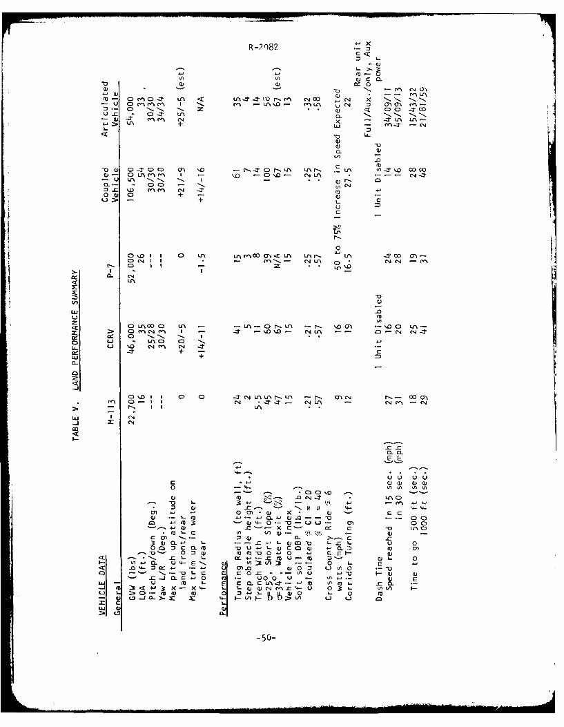
R -2 082
(0
C: -o < C C)' .TcNo
~ m 0 -:r UN Z U'\0-. C
L- i + - - '
-o
-0o CV 0-T~ C> CD m . - r,-:T0 r LA Lr\ r- *LC -a- \'- 00oco0 0A'rMM I - \10 -0\.o- C,4 U, CSj--t
-u Ur\ 11N -.. 11 - V1
'*= 000 % C - 11 "C
0~ 0)C + -- +LC
c
asO I 0 UN N rn 00mO<Lr\ Lir* 14 -TC
r-. 0 II - 'o
LU.
< Col Vr 00 u \ C r n r 1 NU'm .wC
C .. N I%
+wU +M
-J
0. I I -T 0 Lr\LrNr-..Lr\ -r- M 0.C r- - 00 MC1 e'. 0-T cN -t.-- C4 U'\ - CN r~.' - eN
I~ EN
I.--
0 ~~4- nLn Ln
0) -m -0 04L -t C)
-u 1-- oc.a * M 4,
0' M' Q) X . Q - C C(U4, C a-)-C 4---a4 J0 -0 00Cm ~-.4- M Q '- 0 ( - - .- U) C
41 0(U ZU '- XCC w-O 'U IN0~
0)- -- L.- 0L CU COC -u L-.' L- J -0 *am - u 0 s -Q)c a ) n'n.D
L) o -CUCU MU M 4-L 0 4V 0 E CUaL- L.J0 - W 4- I-l?-C to) V m : 0)L 0
0 CL U4 1 j L )-s - 0 L< 04 X . 1 vLU 00 - n0-
L- C c c 0 C . .-. A u 4,a
-C _j CL C 0 -50-0 uL
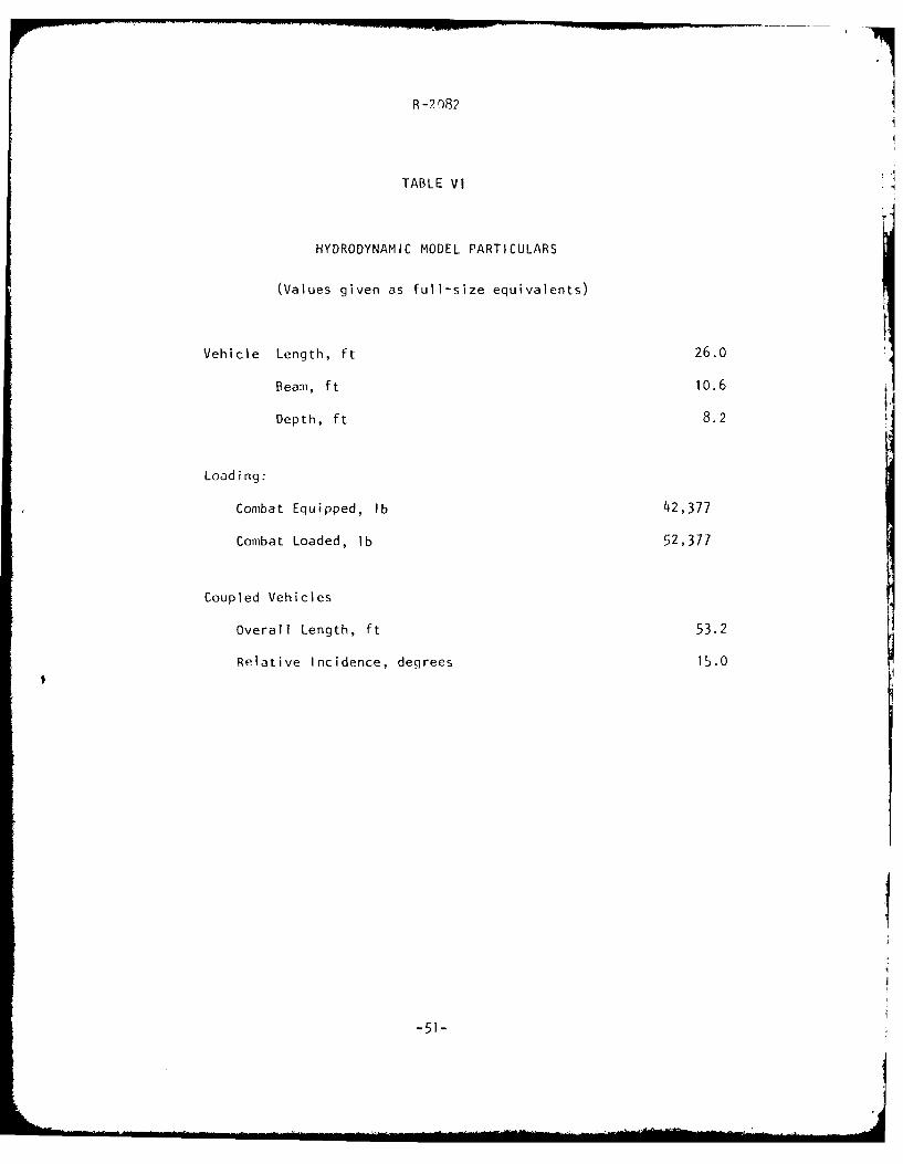
R -2 r82
TABLE VI
HYDRODYNAMIC MODEL PARTICULARS
(Values given as full-size equivalents)
Vehicle Length, ft 26.0
Beam, f t 10.6
Depth, ft 8.2
Loading:
Combat Equipped, lb 42,377
Combat Loaded, lb 52,377
Coupled Vehicles
overall Length, ft 53.2
Relative Incidence, degrees 15.0
Sao"

R -2 082
zI- -~ . C," 4 :
C4
-i cr
0~ CU. C- -. 'L-
- LU
u 04 C-
U
I- 0) r_
C:)
Li Ln
S-52

R-2 082
FORWARD
FREE YAW FREE PITCH FREE ROLL
CONCEPT 1. Ball Joint
FIGURE 1
-53-

R-2 382
9/
FORWARD
ASSYMETRICAL YAW FREE PITCH LIMITED ROLL
CONCEPT 2. off-Center Ball Joint
FIGURE 2
-54-

R-2082
FORWARD
POWERED YAW FREE PITCH FREE ROLL
CONCEPT 3. Symmetrical Yaw
FIGURE 3
-55-

R-2 082
FORWARD
POWERED YAW POWERED PITCH FREE ROLL
CONCEPT 4. Symmetrical Yaw w~ith IndependentPitch Control
FIGURE 4
-56-

(~ R-?982
IL
FORWARD
POWERED YAW/PITCH FREE ROLL
CONCEPT 5. Dependent Yaw and Pitch
FIGURE 5
-57-

R-2 82
_1 FORWARD
POWERED YAW/PITCH FREE ROLL
CONCEPT C. Dependent Pitch and Yaw with
Coupling Frame
FIGURE 6
-58-

R -2 '82
FORWARD
POWERED YAW FREE PITCH FIXED ROLL
CONCEPT 7.yavw -- No Rofl
FIGURE 7
-59-

R-"',82
FREE YAW POWERED PITCH FREE ROLL
CONCEPT 8. Pitch Only
FIGURE 8
-60-

R-7082
< F ORWARD
POWERED YAW POWERED PITCH FREE ROLL
CONCEPT 9. Turn Table
FIGURE 9
-61-

R-20982
FORWARD
POWERED YAW/PITCH FREE ROLL
CONJCEPT 10. Trunnion Mount
FIGURE 10
-62-
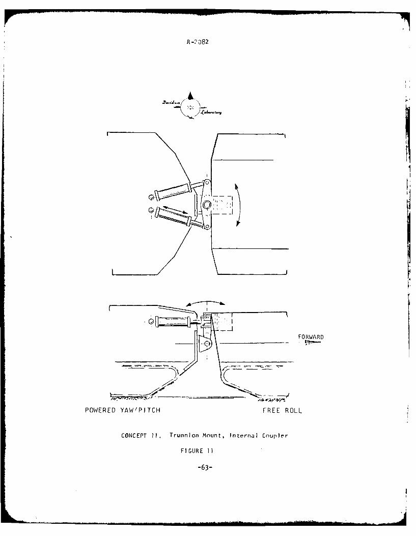
R -2 D82
~0
FORWARD
POWERED YAW'PITCH FREE ROLL
CONCEPT 11. Trunnion Mount, Internal Couple'r
FIGURE 1]
-63-

R.-7082
t
~.1 ~1:JFORWARD
POWERED YAW FREE ROLL POWERED PITCH
CONCEPT 12. Split Pitch and Yaw
FIGURE 12
-64-

R-2082
C)C
0 L LI
Ln
3AMO IVNI
CD
Li C-)I (I)
LiuIu.J /Zcc~I
I DwI
-65-

R 0 )82
AWCYLINDER
7iiPITCH C4j
Q L..L
-6-

R -2 082
FORWARD
LCR-V90 :
890 GHP@ 3200 IPM1
- ] CLUTCH (OIL COOLED)
GEAR RATIOSLOW HIGH
8.62 6.224.67 3.372.46 1.781.38 1.00
VI SPROCKET_VEHICLE -F 9 TE9TEETH
.5 FT. PITCH
YFE CLUTCH DISC_DIFFERENTIAL B-KE
2.974 Hi CV DRIVETHIRU
ARTICULATION
Lu JOINT
DIFFERENTIAL I HP2.974-
L~j 100 HPAUXILIARY U
L ENGINE
FIGURE 15. Conceptual Powertrain Schematic forthe Articulated Vehicle
-67-

R-2082
LU
3 6 N
1~C-9
-68-

R -2 082
7: C)
L) m
L L.) LiLJ(
.4--
-j LA C
LiC.C)
0L Li iL
Hu 0
0V)
*Zu Li-
:D D- 0
U-j
C3 I~cH
F- 0 C
-F :U 4
<.
-69-~

R-2)82
cu 1x
<D ru ICU
Z LA [
Lai
oz x~ V) __
* LU
w 0.(:
C N
CDL LA)
m0 a - w L.0
WI-
zj00
-70-

R -7082
ISl
U)(U -
WW (. -j, (
.I0 C-
w Il
CD I-a Q)
Z:zCD LU2-
4 u. CD
2A 0 0
0 1-EE: 0LL __A_ _ _A_ LD
W 0-
L 0
Ew u
ru 0
CC
w
CA~
U D(A 0 CD
a_ 1% (
t- (n ) U-
-J (n~ o FT 03F -T-TFT- -rTFVFT -TT-TT -
U) U) m aU -
0 J-4 Z: ~ ~ wtzlZ-30aF..
(L)I z

R -M2
Ln (D
ru '
<D u w C 115
oa. -w u
cc) C
an- IL ) 0 -u 0
aa0 I ro
rELA K____ 0__ _ _L. L o j E
WL E 0
C)
LI U
V) 0
- Cr
CL
I-.n
M co0
r-L Z rW Z -n0 - Xo - t .- 4z=u L -
Z -10 C I ILu 0 4
U Xw
I-(~.-74-

R -2 r82
z --
w z0 -
Z cr
LA 0 _- -
0I - ( a
a_ Il 0- C- ~
D) -7:C 4
: zL 0
w1 - 0U::
.r- 4:-'
00u~. ~ C
'.~- :
(D 4-) Lu
N CD
z- D
LUJ
LL CLIL
< (D
aZAJEw n 0 0 !(J.1 LD m cu v-4
0ora. Z wd -
-73.-

R -2 082
ca)
z ry)
-t z 3ra: w -
2- X
0 < -
D 00_0
U-f->zi -u
LLLA
Z:w 0 c(1: <1
_ _ _ co 0N<
C (1)
-' 4LC -
oI-c '0
:00
-4 D
LL. CL LL
*-~I4 Ln LnCL Z:WE: -4
w "Z: 0L) r I-Z A '

R -7 082
-r 'jV I C
rr*p r, CL .
f" co
YO >~~ U
41,k

II*j ~ - 5 4
R-?Q8r
(3T
- JJ1 >.
~f4 ~ 4
...........
-76-'

- .2..
SINGLE VEHICLE
I/
COUPLED VEHICLE
--7 ( - C f --- <
\I
2W
FIGURE 25. Trench Crossing, Basic Geometry
-77-

r ~ 4
i:'~~ j ~1~2 I ~..
* I ~
L C>
~ ~{*~ :~ :~ ~ *
."-*v *~.'*.
k
~: C)0~
~I, 0 (~~)I--J
L (.9LU
.sf
I C,
Ir- -
4 ~u) -I
~
~~ 'j.,
~'
(.. ''1 V' ~
.~ N~I
'*
S ,~ I
-78- -

-r 4 1
K~~O I.-...
1) A
-79-l~iJJ

R-2082 N ~ 1-~
14yf7,~ <L
AIS 4

/;
R-2082 (
r I
( 4.V~ P~)
{igI ( 99
2
.~ I--I
{i~ .. C,
f C
( ;~ ~I'1 :}~, oil'A -'~t~~
(I I LU CC)-uC)
1~C)
rC)
.0
/
A I
r t .j.1 -
'0 '-I
I) A
~

R -082
SITE I
DRF 0GO: BOTH VEHICLESr
SITE 2
1/ 2 40
M-1 13
GO: COUPLED M-113
SITE 3
M- 113 GO: COUPLED M-113
+ 310
W. L.q
M- 113 .GO. COUPLED M-113
FIGURE 30. Water Exit. Bank Profiles for
tile ccRv/
-82-

R-2082
/u
< <
Uu
uC
L))> L
LUL
L
L)L
L-83-

R-2 082
\/ u
c Q)
L0>
NIP

R-98
I7
J LLL
rrx)
-8-o

R-2182
/ cy v2
-Z/2
/W
r/ r
I//"R +
\ /
R = 2 sin ol/2 01 R + D VehicleClearance Radius
W rI-2D I /s a' r = MinimumCOS / I / Clearance Radius
r = R cos /2 R + D - = Corridor WidthIw
r += Path Radius
FIGURE 34
Minimum Corridor Width by Articulated Steerinq
-b56-

AD-AIOI 558 STEVENS INST OF TECH HOBOKEN NJ DAVIDSON LAB F/B 19/3
AN EVALUATION OF THE COUPLED LVT CONCEPT. (U) NNOV 79 1 0 KAMM, P W BROWN, P M BRADY N00014-79-C-0356
UNCLASSIFIED SIT-DL-79-9-2082 NL
2 EEEIIIEEEEEEEEEEEohEEmhhEEIEEIIIIIIIIEEEllElllllhEEEEllIIIIIEIIIEIlIS

R-2 082
30
4C
3111l
20 - __
3C
21JJ
2CLVTP-7
1110 OPERATIONAL N
0 C - 04 \~AREA
0
PATH RADIUS -FEET
FIGURE 35
Minimum turning radius (to the CC) versus speed for theIVTP7 vehicle with the 114C 11S 400 transmission (Note:Converter 1.ock-iip produces constant radius of turn fora given range of spe)CX

R-2082
0[
LLJ LAJ
.30III
S20 I -
OPERATIONAL10 - -... . -AREA :
COUPLEDI LVTP- 7 LVTP-7
OPERATI ONALAREA
0
0 20 40 6n 80 IOn
PATH RADIUS - FEET
FIGURE 36
Operational Area
LVTP-7 compared to coupled concept
-88-

14 -R R-2982
M 113 (STD)-
10
MI 11 (TRAIN) RIGIDBL MODE
010 0 5202
SPE,0P
-89

R-2082 2I
.40~I-
-J
-I
0zkAJ-J
L)U)
co
L~J
LL
~1
-90-

R- ?r)9
V k-,' uCl
u"3
cL-D'-3
LuJ
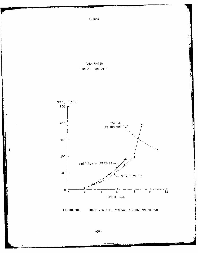
R-)062
CALM WATER
COMBAT EQUIPPED
DRAG, lb/ton
500-
400 Thrus t
21 HP/TON
N
300
200
Full Scale LVTPX-12
+ . Model LVTP-7
0 2 41 6 8 10 12
SPFFD, mph
FIGURE 40. SINGLE VEHICLE CALM WATER DRAG COMPARISON
-92-

R- :'08 2
CALM WATER
COMBAT EQUIPPED
DRAG, lb/ton
500 Thrust
30 HP/lb
400 -
20 HP/lb
300
200 - /
Sinqle-
'"- Coupled at100- / all incidence,
0-~
0 .. ...- . .. . ... .. . . I------ ----- I ... . . . I .. . . ..
0 2 4 6 8 10 12
SPEED, mph
FIGURE 41. CALM WATER DRAG OF COUPLED VEHICLES
-93.
Loom
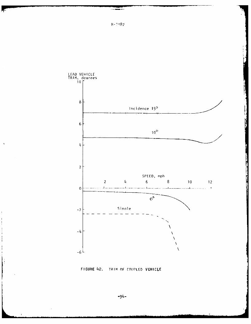
R- 7(82
LEAD VEHICLETRIM, deqrees
10
8
Incidence 150
6
100
4
2
SPEED, mph
2 4 6 8 10 12
0
-2 Sinnle
-4\
-6
FIGURE 42. TRIM OF COUPLED VEHICLE
-94-

R - 9r)82
LEAD VEHICLETr im, degrees
10
9 -Combat Loaded -
Combat Equipped 1
5
DRAG, lb/ton
400
300
200 Combat Equipped --- ',
100-- Combat Loaded
0 2 11 6 - 8- 10 12
FIGURE 43. EFFECT OF VEHICLF WEIGHT ON CALM WATER DRAGAND TRIM OF COUPLED LVT
-95-

R-?)82
ROUGH WATER
COMBAT EQUIPPED
DRAG, lb/ton
500
Thrust
400 2 30 HP/lb
20 HP/1 b
300 / "
200- Single, // 2
~CouplIed
/ .Ca IlmT
/ ' ./
- I20 ingle,. 5Si i l
.ow 1,2i a rg
0 - - - ,
0 2 4 6 8 10 12
SPEED, mph
FIGURE 44. PERFORMANCE OF COUPLED LVT IN SEA STATE 2
-96-

pro-
R-2082
SINGLE AT 6 MPH
COUPLED AT 10 MPH
FIG~URE 4, SINGLE AND COUPLED VEHICLES IN SEA STATE 2-97-

R->' 82
LEAD VEHICLE
RMS ACCELERATION, 9
0.12
Combat Fouipped
Sina le LVT -0.08 . ... .... .
o.o4 Combat Loaded
0 -
O 2 4 6 8 10 12
SIGNIFICANT PITCH
DOUBLE AMPLITUDE, degrees
16
" - Sin le LVT
12
Combat Equipped
8
4 Combat Loaded
0O 2 4 6 8 10 12
SPEED, mph
FIGURE 46. SEAKEEPING OF COUPLED LVT IN SEA STATE 2
-98-

LEAD VEHICLE
RMS ACCELERATION, C-O 1 4 ' , I [ . . . I I
0o.-.4_.o
0.3 -S
/s
0.2 - 'So "
0.1-
.08-
.06-
.0 4 CouDIled LVT
/ 1.03
.02 - \.02-- S irici le
".01\, -- I t
0.1 0.2 0.3 0.4 0.6 o.8 1 2 3 4
FREQUENCY, Hz
FIGURE 47. RIDE QUALITY IN SEA STATE 2 COMBAT EQUIPPED LOAD AT 8 MPH
-99-

1?)'82
LUj
-jLU
zC)
CC
LLJ
-100-

R-2082
10 MPH
12 MPH
F IGUR E 49 COUPLED VEHICLE WITH BOW EXTENSION IN SEA STATE 2

R ?082
PHS ACCELERATION, q
0. 12/ 7
Sea State 3
0.08r
0o --- -- --0 2 4 6 8 10 12
DRAG, lb/ton
500
Thrust 30 HP/lb
400 -
300
Sea S ta te 32<
200 /
100
0 2 4 6 8 10 12
SPEED, mph
FIGURE 50. SEAKEEPING PFRFORMANCE WITH BOW EXTENSIONAT COMBAT EQUIPPED LOAD, SEA STATE 2 & 3COUPLED VEHICLES
-1 02-

( -2082
COUPLED VEHICLES
Soa State 2
Combat Equipped
BendingMoment, ft tons
100-
Bow up
50
Max. - r - -
Mean
Mi.
Bow Down
-100 - . ..
0 2 4 6 8 10 12
Speed, mph
FIGURE 51. BENDING MOMENT BETWEEN VEHICLES IN HEAD SEAS
-103-

R-2082
APPENDIX A
Coupling Joint Calculations

4; R-?082
SECTION MODULUS CALCULATION FOR
TUBULAR CROSS-SECTION
14 4 42 D
FOR: D = 20' (outside diameter)
d = 19.25" (inside diameter)
W 204 - 19.254WL = 32 20.00
WL 111.35 in .
BENDING MOMENT
FOR LAND ML = 4,030,000 lbs.in.
FOR WATER MW = 1,200,000 lbs.in.
STRESS CALCULATION FOR LAND OPERATION
ML 4,030,000.. ... 3,0 = 36,193.15 psiWL 111.35
SECTION MODULUS REQUIRED FOR WATER OPERATION
= 111.35 x -- = 33.16 in.3
L M L 4,030,000
FOR: 14" OD - 13.25," ID Joint
11 14 4 _ 1 3.25 4 3W 4- 1.2 = 53.25 in. available
A-i
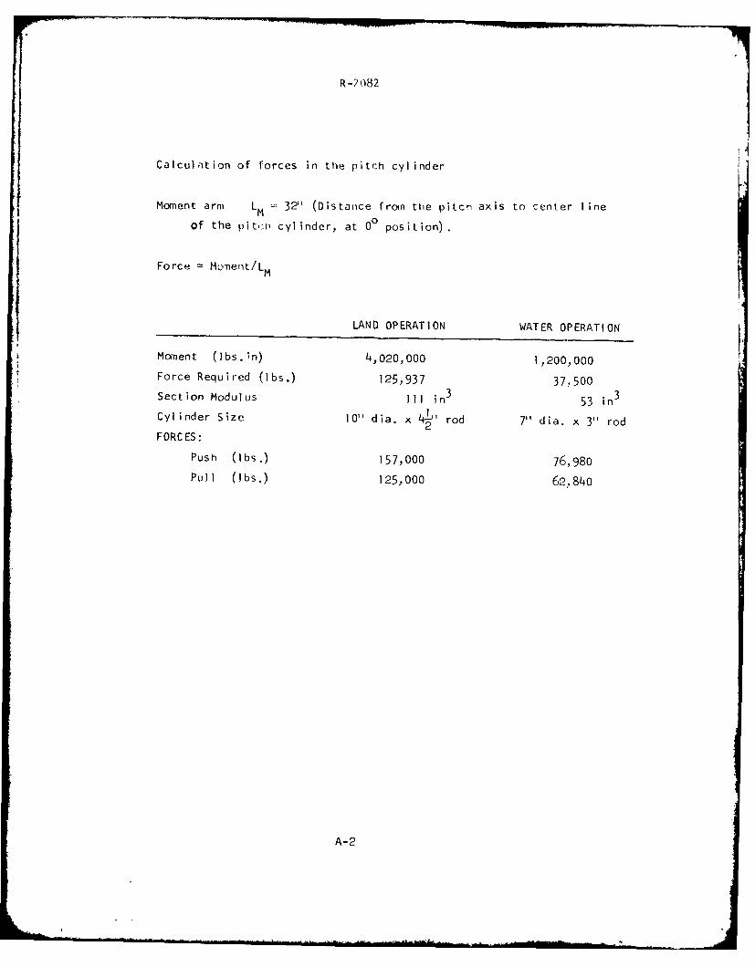
R-2 082
Calculation of forces in the pitch cylinder
Moment arm LM 32'' (Distance from the pitch axis to center ine
of the piti) cylinder, at 00 position).
Force = Monent/LM
LAND OPERATION WATER OPERATION
Moment (lbs.*in) 4,020,000 1 200,000Force Required (lbs.) 125,937 37.500Section Modulus Ill in 3 53 in3
Cylinder Size 10" dia. x 42 rod 7" dia. x 3" rod
FORCES:
Push (lbs.) 157,000 76,980Pull (lbs.) 125,000 620840
A-2

R-2 082
c -Y
-J -'--0 0
- .fl tn! (A-t V0 V0z _0 _ -0 -0: - -o 0- 0-
Q 0D CD b t~0-~
0- C0 00 o: (D U.', ij
cc 0
0o CU C
LU
-C:Q.)
LU Ccc 0 Q)
- 0 L-LL C-) * ~* L- 4.
in a) Ln 41- V) V)n in i-- o -c .-0 (Au -0-j -tLu (a z - 0o - 0 - 0:
Lu 0- C- u 0: L CC) L 0 U\ _LO:r
<o tn 4-1 o- m CD-~ m C tr\n < Co 0 4: o-(\J C) CU
-r I- -T (n 0
C7 - 0)y
-U Cu
< zD
-L (13
>- J >w a- L.
EU F
LJ J U_ _ _ __ _ _V)__ __ _ _
- Lc
-0
a. (u
o 0 Lu 0X: in CL
LuL
) >- -f 0 L.- 0 -j)- CL.-
-Tia Din C) HC) - 0C - LU
LL (.- m: CD -1 DcLu >*- Z0)~~~ -o >--
<c < >- 0X CL. X: I--C
A- 3

R -,'082
-0
U'%'
-4

R -,r)82
Co
0r,
0C0
0
A-

R - o82
CN
Ln
KO
IA-6

R-2082
APPENDIX B
ABSTRACTS
Remote Coupling and Manipulation
Literature Search
'II

A Cum r'i II Lr- o f St r Lc t uI J rits for AsSembl Y. F ielId andF I i grit St,ir at ,ri on Nls l -
8c rig (ji Scat tlIC W~isn (0S 5 G6OAL) I lid Gui i'. I I .R VEOllP3t1 F 0i: 161), I 3E GRA17I1O02 Ju 1 6 3 16 C2;)Peot No): L2-12n9 ll-1-Rev-Lt I,-UMjn t tr) r, 113InIrLJdcJ "e , ,son letter 0 dOated 10 Dec 68. See alIso AD-8359.42L airll A D- flt010 d~LLDi Itr I bUt 1cr11 1imnI t t i onl rio r ioo',d.
At~ra' 0 -,r ot ,a, a C1,1'5; 2 RlurIrC 1 Lo)' ~hcorl t~ir- I I raf - t i cr to ai 1 st trW'i, p ' ol rirlrr~iry (ri CoiC,7CoU I aI(10, 1;;i cri0,11 ~ "C " sel Iect IrIrg al arlt y o f r'ri -II ,) L' If t .i nclIudririq: l, I :,,,I S tacoe A-; 3 n :,tIv arid 5 1, i,,It ,o r I nnsBo u-, t er btar' A ' ',f IriblI y arid S k'lo ir'ait o n j o Ir)t s; and Ra ce.a YJO in tsF. r)i .II t noLn, i fotatfori ) r1r cesign cnrnrider'atioins and
I~tr rg IOr.'t ar in clIud(!o2d to ass;is5t t ,on eqgvner in,,IIi log r I concep t cOiiCe and joot Ify ino its appl icabilIity andfeasibilIity.
Descriotnws : (*Joirnts. -Guided rnrssile crnronnents), Sepan,'atron. PaiylIoad , S toiirrg. Laurv-.r v oh IcIe , , Booster rockets, olc;It edjgu %it S, R 1 10, 'iu mecn.1m I SMrS , Adapters, Ar'mrirg dov i ces ,E -PlIOS IVe 1C t ult or %. Shape d chairoos., IrnOic t fuzes, Nose cones,foa t skhi)eIds., G Iass t ext iIes . Roc ke t erngrr no Cases . Machining,Seals, Discounnect fittings. Guided missile models, Design,Opt imizat ion
Identifiers: Muinuterran. Saturn 5, NTISDODX
AD-845 012/4ST NTIS Prices: PC AOS/MIF A01
CMtfcEC1OR ALICIING DEVICE
lot,,it 0.i onto Hi,AU J uril? P,ir n. Cjarl A.
02t.1("3 Fla: 19A. I 3E ISGRUR40 1618 "mI' 65KP)ii rt11' 18A, .a r I ein I (- f " )Ii Ccrrnnrr , n. loner I- f ('a tc'rfrItj Wa sh i Tic;tn' q .. .20231 . .0 . 2b
r e I v.i , e Ov ,t (It I I i I' r, in n I irin "; s tem". i nn I Locr Ir Isel'i iI in - riIr(,11fl !?vI c,' r)irl iih r'!'r ts tn h, c,-)1 r! o q )f t ,o ig)Ui IIt ', f or, trniii',lf i, riq a hIn or' t on rcdo) trunn urn' I o toanc.tti r' if, Itn a r 1'.n'( t eif'eMIniCO s vs tern. 7.m" cunrr'',tc-a1 1 i in i oi d-v 1' ira t' Ii 5I ) I ' ne d I(Ii he i conij I I a I I f t
Sv~lnrs.Tho ',el f-airlii ig v C ernritS the~ couipIlog of t ,o
silti ri Liii t , an0 n11y Y1i0 Sele Ct I Vel 1y re t ai ned on e i tther t hemiale or fi'rnale port ;.,,i.
DeS:- ripztors: ( - Posi I t 10m1gj -dic I Ma ch i n er' y. Dr scorrIfc tfittinqsl . ( *Dr scnrnnerA f i tt I il' . Pas it i on inq dev ice'5(Michnrfnti-r y )I). Pa tell t s. Design Connp r LPII gS . HandlI Ing,. Dol I es. Bobonhandl irig vehic les. Bonbs, G,r hoists
Patent 3.183.777

R -2 982
N/8 13089'.LASER SPACE RENDEZVOUS AND DOCKING SYSTEM NiT0411 . .STUDY CONTINUATION Final Reporn. Feb 1916 Ju'.1977 INDEXE D KI YI LI '(ON'.I CIHON ,.,, -,
A l , H H,,r.,n u S L r, o d F 'A.'m,,1 ig 30 Jo . . ..
.4.V 1189 ,
Il 1 48 I ,I'' 7 R) 00713 ,'A'I NTIS . ... , . -.- .
%4 1, AW
:,, ,,,I ...... ... . . .... . . . .F
w l, k l
,7 5 S ..i ...* . ... ..s A ,i ...
N 72 246861 ... 'N* w.S s' i Cal IN71 22712 ~. .. ''LONG LIFE SPACE MAINTAINABLE NUCLEAR STAGETHE DYNAMIC RESPONSE OF AXIALLY COUPLED REGULATORS AN[) SHUTOFF VALVES Fi...al R.!portTUREEOROTORS Md' 79jl;' I. .136;; .,
I.
,,, & -Li ,j, o , So V, ,,; i S3 0 0 1 r NA..A ( 14 1231,l P-4 W A 7i1)1)7- Ava I NTIS HC -S1400
70 7P,' SCL 18E
t h .. . ] , . •
tt~ ( , h A " r :,l" I -" " i, : . , , . ' ! b ' I )' If it.. ..
70e 782' TI S~l.. . 'u.li, ... .1 57,
5i , e'.'. '' ' idill! ' "
q, 11-1 '1 ...... . - I- i 1 fll1- -['%, ""(J th
fe. If tiLATC. E CTO UNTNPtTI' I', ' 7 i"'1Il "I. tid T 1 '
11 ( , l m.'i iS l ;
N ASA 22 1 .... ,.37,3 I' . .. '. L.N S E F T D OC K ING A N A L IGN M ENT S STE
lU BO R.'' .S . .... , I'll, 9.l ... i,,.
N 71IIl 2489 ' " . P : LI L )t~ 1.1.d I I( '~~' A : 1 .... J ') ' l ,,1 i l p l I.....
31 7 9133 6 !N 1181 .
N75-1482, 0'n., tI(, l''. I,
l' .'l ','1,, ') S1''' CI le ',' aI,' . I/Stl Pa;.; (.,.,.s 33 ;w.S v' 1' .,, . .l' C' 1lll , l l+ lf• ,)t
SPA CE TL ATMAC TTI DOCKING CONTOL STUDY 0"'. F'll'',t ilAll', I rI 'I i
D o."l 1.' CJfll ll> Ik ilc"t1 1 T t , LIll l lf R ,<t ' % l 15
b%(*' ~ ~ ~ ~ ~ ~ ~ ~ ~ ~ ;% 7 (W . e ,,,- N1
Sr
A ( "' I. . Ii.. I' I ,li r'] Ir li
*
(,'l < 'v I Ill,,t lI l¢, %, rt , !Ii' !liI 1, lpllr(
l'11 4(4" ar (.11 .12-1)578~ i )MS 0 4'S Asl1
'1 'S 1
I"''< 5 .75 tI', ''1 '''i' 'I Il,', .'.' -< I .elt i'-.' %, A , ! i''~ ll l 1
'd 1> ]I LISILII 8 -2 , - I I, Pr( r f * 1 1 1 , L, I A %j I
SPAC TU AU(r l
c
T OM AT11,lll , IC D. OCKII [ING CONTROL ST D , !" l (Ill ; rl i)Jl Of", I Ifl It'lr( pllfllll
lf+lR III
F ... al Rep'ol'+ A * . It 'r h1 " 0 lI I d $~111i
i lhe t<
j1Ll i .3 ! ) 1 1 l, . -1 I 'l ILI I ...... ....* , . l~ ~ J F ' tf
Do'AilA (.R 120578ll~,' tMSC D4 1-2) A - Ilti ',If, Il iildIlk ~ I"
ta.-t A'll h0 ptalI i-~ o It' Of, t ll G
"
-1'.l' I ' .. 4 1t
.. I I -, , t ml a!w l l - ,l - a ,,-1 A , 0, , P a . . i I , ! l l i , i 1 l ' l t r , l t i
I
O f,, I ,I r
ifi'A (tl 1 0 7B L S : 4 )4 ,R I' • l l'l ' h "$ Tlt i,, 1i
* +,. . " , I i . . il+B-2 ,, l I p l

R-2 082
SIDE PULLAWAY DISCO JEC1 APPAPA' US
Po tott Is'I.iq' ,I 1 ' At V ,Force
AU I i l: M C II A c h , C t,.,'1 0 P .03.-1G4 F Id: 1 3 _ USGDTI','i602
2 N , 365M.I 1) t or: 1. 8
A v.i I ab e frorm Cy,-r I o s i(ner o f Patents. -,1rlt . D.C.
20231. S0.'O
Abs, t ract : The dl_-t . c "i t d Iatr t JuS L IS ofuI ar 3 r' ;k t 4'1c l
.i' t 5 i ,1 1 lY ka or C hac Ii iqh . tc iy ri V P3 f
3 '2 ll' O t 0 0 -J e (l' -r I :i t t ' ;t '. o f h ,l, I. 'r e 'I, a t I ns to
f I IQ;it 1h t i t d i),rti r1 S ;1 0 11s o o r' m .r- n cr le l iCk diiS C ( 'C)!) t
(Jv, l rosm the Ii 19 G Sleo t ra t'iierso to tile f Oirw r'd
r'ovc erIt of tie veniobe. One part of the device is attacheot
to tO.e sled ri the tieht hjl f to the apparatus.
Det;ri ptors: D-Discouriect fittInq5. Test vehicles), Patents.
Poc1lot-pripelled slei. Hose couplinOS. Electric connectors,
Opel" t on
Patent 3.215.970
Relno te U r-"arriot Wo rr'k System ( RU I Match ing Latch IDep:ir tmpnt of the Nov Wachgi tori 0 C (110050)
Pat tAUTHOR: Tryroi . P:lI V.Dl1 5I lf2 F ift: 133. 1 A, 90OA CRAI 77013
Fi led 12 da 7¢. pa t l I d 26 Oct 76 5;)
Rolft No: P ,T-sP L-4 2 1 0"' 1:ltI -3 987 741-. .I : L,
Super orl', AD -Lr002 DI:'.
This Gov rrjr,.1rrt-owi(,tl 11 t iortl lval ohI; e fO' ('. . e ;
and . Dor.sIbI v. fors I i L i;,I 1 01. Copy of patrot ovai 1lL IComrrii ssi cer I)i lat cI)t Wa I iIcitoi1. D.C. 20231 10.o 0.
Ah3t,'act : T!-, l ttrlt It " t a doyuce -h v I , , rruuIte
ifi ite''cuifoc t i ) Of fr I IF ' I,( io,-a vehi,-II tfthereJ to -ISO'- ' LI 11(1 'r-"I - 'a 0 kCu-I;' y i. it l; cah ' ":) ICarlir cr 1 c " P Ii veofi ::!, t, I tot h r',rn: t itIe extel c d" h';c', ''
a lr i ,st.','t)l :,l-rI (If, t ho t th I e" cl hide CI rI' d f tinctr, irrIlv ti 11l)(,y alrid 1 k t r e. t' tFth1v,_,-ed Ieti il . DWr'inri theCOll, ' t i n o f t hi t Vter cI er the C;,)m Is C r'!. 0 to ci',.a the
prI'-r aro,'h1 into a IIti 1 1 ' . cirr1 '. C,rr , I e r ,Ii tic SO or1nd
U I1ie, r-;poa vehic 1(. "r'rall l I s are c ,;,-re,; r Ito a n arirl r
Qr'rrtse on the ;Wiod sl. 'uIiy ar a , ,-1 ' of rrpiW ; i flr Ire i rcalSO: rigs rOrchlrtlrICIl Il iY t r' -It , lock the A 'ls in plIce. The
c.,:ot ,on of t1r (ph' ilc,' wor'ki,, oi e a collar- (r'. the Prod
a s ,ceib I y and a ", cove on t ho lat ch i riq ai, omb I y m,akesacci(ental d .11 il .aqom,-ijt near' ly imooss ilb e utlt I I hydraul iC
actija tors a,, i st tihe fni'C o ir' ,'duCOd by the sleeve spr' i rig toOvercome the force exerted by tlre col lar spring to release thepaw I s .
DoS( riptors:- L*nder'wtIr vehilri-,, LatChes. *Patents. Co,,ialICar Ie s. Nlechn icajl cI_ lcr ,. t ler in . Couplings, Releasemechan i Sis . Rpr;ot e (ont ro I Unmlarined
IdeIt if i'ers: PAT-CL-1 14-16. NTISGPN
AD-D003 298/75T NTIS Price: Not available NTIS
B-3

R -2 082
Coupiiinq Device for, NIvnj Vehicles
Na~anlAerorrau11,tiCs. Ind SPIaze Adminlstratioti. Goddard Spacet-liwhIt Center. Gr'eerrelt. Md.
Pa 1, eat Ap:)Ii icat i onAUTHOR: Rudmani. A. A.
E 2 12210 Fidl: 22fl. 22A. Ql4C. gOa STARiGiGF i It- 11 "713 2.3tReoot N'r: ',AT-;WPrL-y:7 436. NASA-C ASE -GSC- 1 ;2322-1Moll i t Or' Iand. I)srb I for for'e i n I a ciens injg. COPY Of alop Ii c i~ COnav a Iab) 10 NT I S.
At,;t rac t :A "& rria Ysten %is 1,,Signed to Capt ura arral/ordQ01p 0c dc V Ce Or, 'eh iCe 10riavinq rtI at iv rf motion wit tir t'5p)ectt o a 11o t he or var o 11C Ie , The r (,: rarr i Stn i OC I dCes ;n o ntbard
Con t "0 1 1 co I ,~'~ b etI,'r'ase-,) OOarlocattod o-t thcreno -, fa1con trol I Ic . roar1, 11 1 1 l; IIto0' Spr'tt'rjj caoa' i d by 00o mov a rig . o'n it ole.The iris wt -rr)ly ti, means Of thie rramipulator -sr -0em c-rCar'clesaprot1P lOcatcd Or, the other mo,1ev g vehiCle whaerouirion the ir is
a-nsorOly as act, vatod ind 011i0c or' [re it' i s e I Paraornt s closearv',U n j' tic, prcoo. thuSC a;ptat'i fig and aiai l)y al Ipa~iirig thteot raar sr'hai w iti the i r iS a-,senrrnI y. AcdI t i )nz; I I , a rotatorasraals s rola for, sciiarrrra the iris asn;eratlv in arranner adapted to engage the riroL3e of a spinning vehicle.
Descriptors: *COUP I irigs. *il-riulator's. -Remote hxldlIi ng .*Rocxet volliclos. -Patent applications. *Spacecraft dlocking,irises (Miechianical apertur'es)
Identifiers: NTISNASA
N78-25429/9ST NTIS Prices: PC A02/MF A01
ID NO. - E 1 0 -1, '1a79 I 4(;179Aat,'uIt lC C000rrla 7 for- Eor'aa"rak G aI.- v 1 2sa rr 17 S,,;,t 4 11)70 1) 170-1 CODEN: RGZIA
IaIirl A,t i,1rrrmacahr' has rl'VeloO6l- a COuJPor with automfaticair aviai 01 -,a ticar~ as1 -jh i ch can mate w ith toe ~ii 5ior Soviet SA- 3 d.."ig~ Trro air arnd electric CorapI rig unitdesct'ihl ,d hirs I poa u
t m 5tVaI-1rot SLaPPOrt which helps toredulce Aoar cr, !sliding parts. The stages in the couplingOpea'atain are explairied.
DESCRIPTORS: (,CARS. *Couplings),CARD ALERT: 682
ID NO.- E172.(g,,Il7 2 r,'l1 7On rma n- nra cI -r aCa (51 'J0aIi rarI f aI I too control of a racrrr are
Aim It .t a: C a,ritrol rar Sparoe '3, Proc 3rd IFAC C(D-f aa'7-&197(). P.A. I-<C p 35-1
DLSaQsnA:,rS VEMICLFS. #Cortro ). AUICZ,,ATIC CON111OI..CAqri ALETil: P1,5. 731
B -4

R-2 082
-ID NO).- E172 YO36130 2301"'0OSY'S tLern Of (1In V'Ii' I P01 l..rI Or uks . I Fltrer Iluse F Iur f ocrorIer
f UP" Lrl t or'sl 1;_I idl I ii Ariif q;rL)-F,-Foorderrr lHed', v 21 it 4 Mar 1971 p 206-U
Th is Itjrl IP dcal 11 ,th thn' di-ve Iopmtrit a nd Ii~.s tat,, (I fetq Inee i nq of a cirInrsrless po,. r trucks systeP. usjing sit- ifltrac topis. fork i f t tiuck5 ciidi (I- f Inor t rn- ci- A ~hif I m )11Cap3ble of revers i I. Autowat iC Coup
1 inq and d .:Coupl ir~q on)
the tractor arid pallet pickup) and depositing on) tne fork lifttruck are possible. Iin German ejith Enualish ihstr,,irt
DESCRIPTORS: (-INDUSTRIAL TRUCKS. *Ciintrol). (TRACTORS.Remort e (,,r)t re l,
CARD ALERt: 663. 691. 731
017S19036*4 Martin Marietta Corp Denver. Colo~ N71 10782'ADOCKING AND RETRIEVAL MECHANISM "", F "-11 . r
cifiJRotwrt Tewell and R-chard A Sperrer /1r NASA Goddard CLACK ATTACH AND RE LEASE FLUIlD COOPI NC
Res Ceiit,, The I Ith Aerospace Mrrch Syrnp Apr 1977 ASSEMBLY Flat.'rtP101 110 refs Tor aearlalriliy sire N78 19026 09 99) (SrIf P i i i , , . 55
.torrtacr NAS8 3 1290) 16 M. 1r F , 3 A; .I ,Avail NTIS HC A I/ MF A01 CSCL 22B N A S 1i. CxI, IF" 1 jl,
A, erryrreer or proiob, Ie rtr hIrrq arrd ret leval rerh aniso, US P-it rir r 3F, 7 1 i* . i.- iORWr wich enairles two SpaCec art to dlock alit be sitiitrirally A k "k .F
P.rrod orr orbrit is deiscribied Thre jo irrng cf two spacecraft or ' iri rDsiticrais orr orit siippo ts Irit are In, ricer) iacti ac tiasi ti S UsCS h int. . 1..
is payload sevicint i~riynrr rs erea ir se'by rr ~ ri i i i .p. . r , .,iongri Spiace systems Aril~rnr,rrres of nre PPM i,, lirtle 1 is a IkliuiF ii 51 . .
nonrmpact dockingt rrreChanrsrr toes nor rerirrer rimract ahsorbrnq r . .... , ,, , . r , . . i:'reChanisms or attituide Stabilqaor orr rr the larger spicecraft iscapable of docking to a iprnng spiacecraft and can spin ti 0,~r~n .. . i i .I i '.. ......arid deploy a spinning spacecraft or payload Author .... i....i... r..i . .~ i , ., i ~
fJ76 21245'. MA,"!r 1,' V i. D,--Srj tr Con tir ' m ' iiIiiii ii ,fi It Jr . fl, 'I I:-.,r iq r niSPACE TUG DOCKING STUDY VOLUME 1. EXECUTIVE ii8SUMMARY Final Renvoir
1AA .l14. 39 Mii R163 'ii 11 A&iC NtIS HC S4 (0 i ip
I,_-OUICK RELEASE SEPARATION MECHANISM Pitt rr
P i .i ..... .rt u n i Ir., iiitnr tio Ni AiA.... tni .nt a....r i I L I S i', r, Ai
is1 t i. ii~iiiiric . ... ti,;i rtis rinli u.F ..i.iir .t... 1, W - t. ...i .... i . . . p
..... .. .. .
...........DUCT COUPLING FOR SINGLE HANDED OPERATION ...... t i ; ... i i, .
kipii~~~~~~~~r~~.i. 8i Pr,.,. iiclrq n /i, I . isP i 551 i*' l oi 'i i '
b73 .01 MI hfiI .. " , ....
j.11 S , t J' (P,~ 3 54i 1 2 ,UJS Pr,,nt /iuil Sr, 3307 F5 A-,. I ) P I W fnr, CSF Cr ( 1 131
A ~ ~ ~ ~ ~ ~ ~~r q,11 Ir, ,,I !! ! "II- I r, I tI ', , i. I '."
-aV - .. I ..... ", W V -5

R -2 982
Aui riat ic kec, jfe Cwit''' Coup ler for, mine Cars.
Fos (er-Mi I I -r, A ;at e- Inc WaIt ham. rMA-.5 . O'pa~u ofMine". washir''Itun. D.C. (142 40)
Fini 1 ct 4 Jun 71-1f;~ Apr- 76AUTHORI: Alki', , )I ,'1, T.: Apun'ck. Anthony A. it,: Lane, AlIan
j .n..Lo rd I Arln J.
*D23 /1IL4 Flo: 8 I. T14 fk GRA1771316 1 ri , 7 6 1 3)PCont inc t 103,16042
At ;~t ract : Tliis r''Partl doscrioeo, the Footer--Mi li, ;:I'adra'i that
dehiqnd.d lued. bkni I t. anid tested an L %r;rt , f't itecant rol mm ii ro ir couot: 1
.'. 1 hi; re. cooupler qi vz, thio rintii,-von
thte Iloc Omo't i ve. t 0 t ",In Smi t tPrak i q intol 1 1(1'Ice to t ilecoun ied Cros. ond to dlet ef'ni ne ifthe trip is intit. . adue to dmra i I ii-n t a1i1 f'UnclWay C3' w ai I I be i'cdo, (d as thre
z ~~~~brakes aro aU t nrit ;a 1' y alpp1 I i d~ i n ary Y OIC~u LIed cir .La.br'ator'y tests desc'Jrdhrrt be nrp~~ on thtecouolIer O t . A,,,) ic.-i LionS inrclIude,. bu t are not i m it ed to, theunit train systemi.
Descrnirtoro': .CoalII rir1iin. , M ine cars . 'R,2mote control.*CouplIi nqs. NMi ne haulIacle . Aut ormat ic cont rolI equ ipmrent, Brak ing
Ident ifiters: NT ISFIIOM
PB-265 558/7S! NTIS Pr'ices: PC A07/MF AOl
B-6

R"?)82
APPENDIX C
ACCELERATION CURVES
Various Coupled Vehicles and Rolling Resistances
The upper curve represents the perfor-
mance with both vehicles powered. The
lower curve represents the performance
with one engine disabled.
Figure C-1 through C-lO Coupled M113-Al
Figure C-l through C-20 Coupled LVTP-7
Figure C-21 through C-30 Coupled LVT-X

ru
IL j C,
E C'
aw(D :> c
'-4 CL. CD-jZ r :
* . 4
XX 2c
C)
______
cu
w00
I--
(.n 0
IV) CU)
~ ~W 0 FT TT--4vVVf
Ul ") z (A
C-'

R -2o82
iL
C4
a. CU
MM-
IF- IA __ __ __ __ _9 Z>O c
cuu
W
- IL
C
w
(tI-
w4.. XX
WxW
I0-. ) x C
C- 2
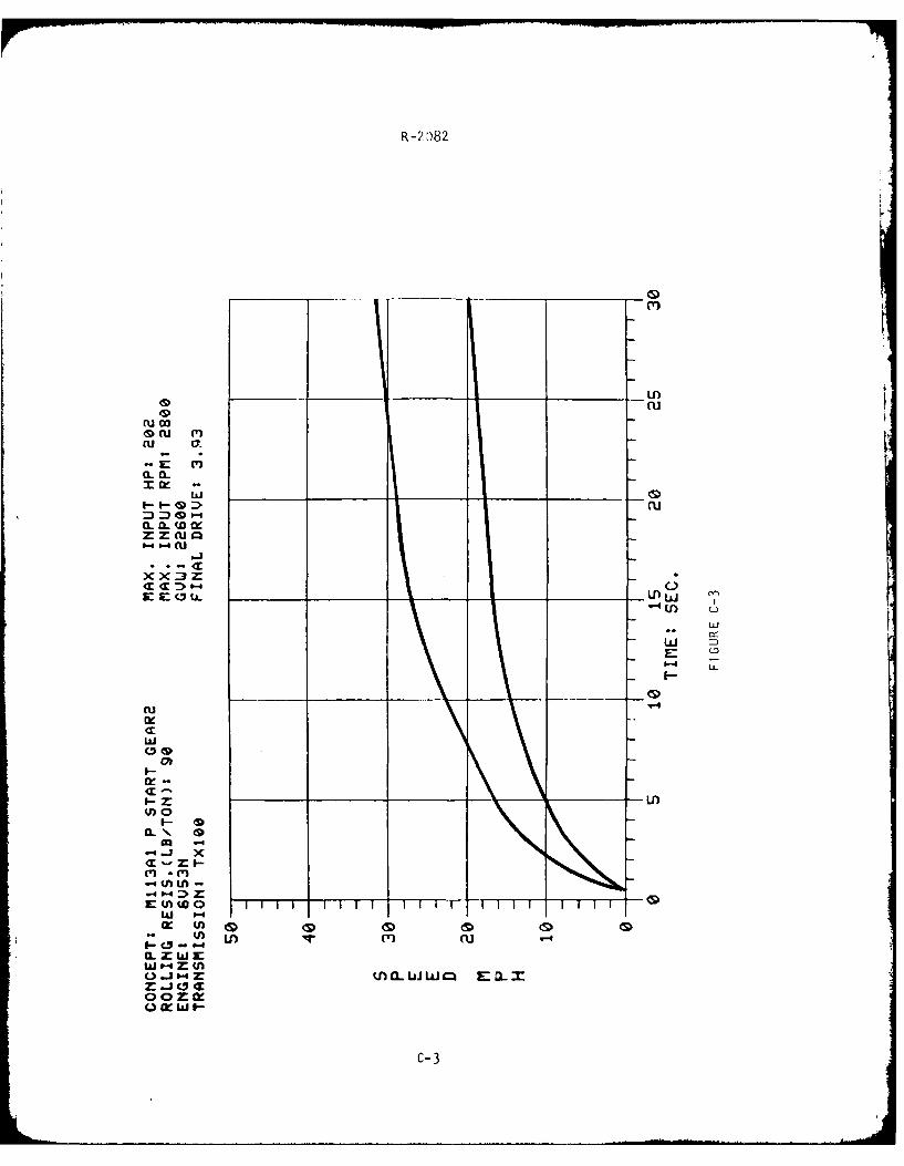
R -2 3)82
____ ___ __ _ ____ U)
CLu
= ru 0
<Cu
x X:3 z
u-J
w
I--zOU
<- r-IM --4J " X:
E: V) W 0 1F FTTF FTFFw
-v U) U)C? -
U.J " =& KCUW E-a
C- 3

R-M 82
X M
-E (D
CUU
C=-
E~U r_0 .)nC
w
cu.Ir-
w
I-I
.4j x
LI#1 ) -
w > X- Cc w I) I i T F
arw 6.4 z "'4Co
0 1- w I.
C-4f

R -2082
CL C,______x___
o
.*-<.tu c
w~~ U:
_ _
znJs
W
10 -4*xw
(ALA
___
__
CV) cuY
CL Z W w
C-5

R-2ci82
______ _____ A
0 CL (
Cu 0)
CL IL
xxIF--4 I. W :>c
CU)
IL
IF- L
(Cu
I- W
I--0fln% *
W4 V) LI)
W ) #A W
S.Lon* U 0 LA
CLI-ZO X W W
c -6

Q U)cu
~cu e'
CLwE C'
CUu
L)
w Cw
LaJA
.
-U)L-U)
Wh
.(i (n
0 V, LA Cu
0 I-4w I
C-7

cucu
XE (Z
a. LQw
~~CU
Cn C DsE~~~ w-0L, A0
W
I-
<r
dno 4
.4J
C - 1-
.4 0-LaJr (A
ooz)
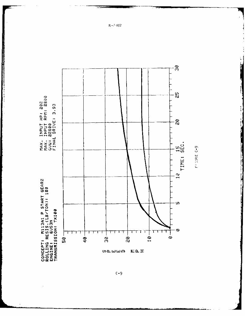
Q(U
Dcu m
XE m
S w r
CL a_: '-4 mZ:Z:(UL Q-(f
- w
(Un
a-
w 0
I- Z:
-3 -C') . C'-.4 V) Lfl-
-n (r) ( U
z - 0 C 1
C-9

R -:1082
ru
ru w<9 lJ (T)
cu O
CL CL
O wL:>ZWQ
M C D 0-4 C
w
IL
ck:
('a
--
-
C') VC) w
(fD
0 (ft == -0 w U.I.*:-'3. U) C
oozmr0 lxw I-
c-10

R 98
EL
~ww
I-- Z( u
D :3 I-I
zx~
u-Ico
IL
ni
w
- nL9
.W XO ( FA ~ -fTm~mFT
0 cc w I-m
C-11

R -:1082
0
ew
11 z~ (UjUN
o.: c
-W -
L)J
ww
I.- I.-
:>_ _ _ _ _ _ _ __ _ _ _ _ _ _
X-ja
IC-1

R=?082
(Vm
i×q- -ac <D c
-j-
X M
I>
04
w
I- LL
(-w
I--
u~fu
-J fl (L 0 wT =iT FT E a-T x T T
0 m w
- W U) ( C- 3
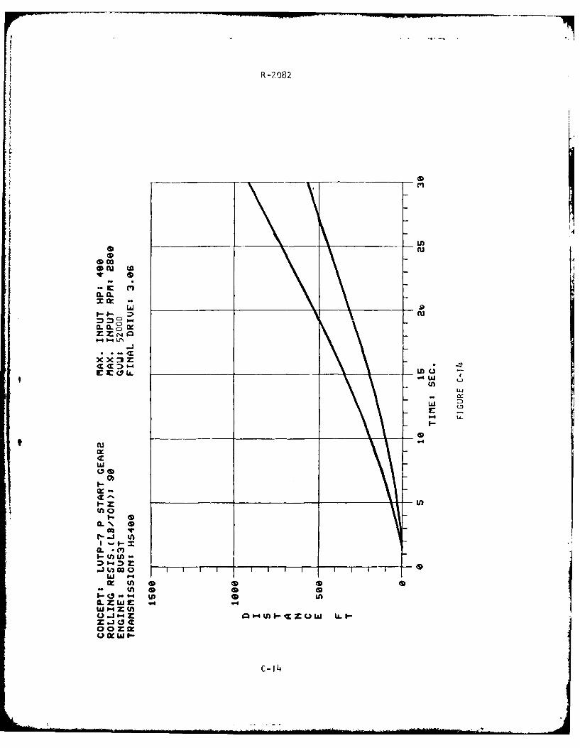
R-2082
ecu u
wF-I--- ru
04La.LfO
*-4 w utn
ww
(S
U~LoI-
0.\ m
V) cor-w
~~~ uw w
oozfeo w I- -
-1

R-20)82
4.u
t9__ __ __ w_ _
C)l
CD i
__ _ __ __ __ _ _IQLAC
<r
CCD
=:, - (Zcu
I--
xx~
CL)
Cu 0-4
Ir CA
I-j 0c
Q ( wI-
L m I- mofl ufl -

R-2082
=)30
0. *Cz .w G
0
E 0 U.XX~Z
_____ ___ fl(.
U
C5..
w '4
I-
:- 0
w "-Ir (A<
(A.'I-win.
l0 0 0U)0 U)w -
a-ZWE ,c-16

R -2 082
_La0 cu
0
X w w- 4u
C Cu
: 1.4U
-JL
W~. s-4
ILZI-
z its c0
~C-17

R -2 082
CK,
w 0
- .:>c
(- . C
a.0 -- ,. 0
-I.
___-__ IQ IA
I--- W:> n x
W 0.4 1
Iin
z -100
IC-1

R-2)82
-~ (Y3
0.0N
t .- cu
C C)a CU. ___ LfW
w
x LiJ
CLL
r- -3U(
I- 0nW m 0 77T- TT--
W " .
I-- Q "-
C-19

R-2 082
C,
cu
-L
CL (L
:3 4 , -.ILC 0a
U'NU
:> 0
f -4-I-
W (D(30O
I-
I--f (nfl
w
<3 - 61 Ln 0CL.ZWE *
U0-~~ L&.I-I
C -20

0-,C82
r,
0_ _ w_ __ __ __n
F- - fu
CLal (L'M
C C I-rY, 8 1
Y4
Ln
ci 1
W -
-J V m n
0-3 " z 0cwl FTFTFVCFFFF FTw -33c
0 0) z 0 0 00 lk ) I- (
3-0C-21

R-21)82
CL.
*c cU.I)J t
F-- CV :D0M0..
CL (L CU
:>C'b-
-IF
I.-u
IU IF-- nC
.j~I (AIx-
z -L0h
C--
I * I

R -:982
(T)
-L C '
XE Ww.OLiJ _ _ _ c
xx~r 0 U. LALL
LF)
I- - M
CD0
~.4
W 0000 0Q " z I q m a.ww w za
oozroK w -
'C-23

R -29082
rd~
wnru m'
-E a
W~~L C_ _ _ _ _
CCu
V4W
Im.
z Lh
I- u
IxnI '
10 CD 0 I)
0 j " z 0"0I-COW I l-Z-Jocoozir
C -24

R-?082
CLuow
.q. c'a. 1L-C
*Z Zo a
1:X ILJ _ _ _ _ _ _ C
I-I-c~~ (
EE(ts 0 19-i th J
x~ m :
((U-4 (
0jOD C
Z.JuOw
0 Im 0 I.-
C-25

R-?082
CLC
0 wU
Inn -'m
a. & Y
-E 01LL
4~W -- W~
-JL
L)
00
W0x
I "
I W E-
W'4ZIn
C-26

S cu
U) ru M
-E
zzIX
E 0 LL Lh wv-4)
Ln W
IX (n
wz WU
C-2

R -2082
S(
r)
w- m q
W4W Cj* (3 a
w
0-4LL
Lfl.4
x0
m00
U - IA S
W~,4 CKZO wL
C -28

R -2 082
* cu
* ~ ~ C ILc,~C:r IX-
zXX3
<rV
CC:> D4
-4-
z -U
0
D X1- (A CK0 Tr--
1lf TF T F FT FFTT FT -
OC Ul mq ~ u-
0-EWE
C -29

R- 082
* Cu
Iw cu (
w~ &,
:3 C,
K a ___0_&L_
Cu
ZZ-4J
~ 1XX2Z
* 0
ECL L __ _ __ _ __ D'4W C.-W
x (T) (
1IF- cul:>4 0 xI.i IA K 0 T-
W_ _ __ _ _ "_ _ __ _ _ I
CK 4D'S
ozm
0-3

R-2082
APPENDIX D
SOFT SOIL -- NATURAL OBSTACLE
CROSSING ANALYSIS

R -2 82
/
\ '"T N
TRACTIVE FORCE
T Force required = R + W sin 8
R = Soil motion resistance RTOW N
W = Weight
8 = Slope angle
N = Normal force = W cos 6
RTOW = Resistance to weight ratio
Available from Soil = A * c + N * tan 0
c = Soil cohesion
0 = Soil friction angle
A = Area of support on ground
The area of support depends on vehicle and obstacle geometry.
For this analysis, it is assumed to be as large as possible, i.e., the
smaller of 2 TL * WID and 2 * BL : WID where:
WID = Width of one track
TL = Length of the track on the ground
BL = Banklength = OBH/sin 8
OBH = Obstacle height
One should note that in the case of the single unit, the forces required
are completely determined in equilibrium.
D-I

R-2082
With coupled vehicles, the first unit can be in this critical
position while the second unit still has capacity to assist. (Of course,
if the obstacle is large enough to contain the entire coupled combination,
the same immobilization will occur.) This situation is pictured below:
R I
W2 .. ~OBH
N 2
In studying this situation, we f irst considered those obstacleswhich had been indicated as NO-GO's in the LVA Scenario I for the P-7.We found that the geometry of the coupled P-7's is such that the center
of gravity would be over the crest, i.e., the size and ability to con-
form to the ground,allow the first unit to attain the top of those
mounds with relative ease. (These mounds were about three (3) feet high.)
We then looked at obstacles which are large enough to support
a single unit on their slope. (As noted before, if both units fit on
the slope immobilization is not affected by coupling. The gain is in
those intermediate in size.) Unlike the case of the single unit where
the desired forces (tractive and normal) are determined by the equilibriumi
equat ion, we now must obtain four (4) forces and have only three (3)
equations from equilibrium.
D- 2

R -9 82
To obtain a fourth relationship, we restricted the study to the
extreme soil types, purely frictional soil (sand), and purely cohesive
soil (clay). In general, the tractive force available from the soil is
a linear combination of the contact area (A) and the normal load (N),
Tractive force available = A * c + N tan 0,
where c and 0 are the soil descriptors. In the case of frictional soil
(c = 0) it is assumed that the tractive forces on the first and second
units will be proportional to the respective normal forces, i.e., T=
kN1 and T2 = kN2 . Then the tractive force is available from the soil if
k < tan 0. For cohesive soil (0 = 0) the assumption is that the tractive
forces will be proportional to the area, T1 = kA, and T2 = kA2 . In this
case the force is available from the soil if k _< c.
The result of the analysis is, for a given soil and obstacle
height, the limiting obstacle approach angle for traction of the vehicle
in this specified critical position. The difference for the single and
coupled vehicle provides an indication of the capability of the second
unit to provide assistance in obstacle climbing. It is, however, merely
a "snap-shot" of one position in the entire traversal. For the table
below, an obstacle height of 200 inches was arbitrarily chosen.
LIMITING SLOPESOIL TYPE SINGLE COUPLED
Cohesive c = 3 psi 14.0 28.5
c = 4 psi 23.5 46.5
Frictional 0 200 15.5 31.0
0=250 21.5 45.0
D-3
