iii. preparation - yanmar.com
TRANSCRIPT

III. PREPARATION
3-1. Fuel Oil
Use well refined diesel light of such as automotive diesel oil.
Keep the fuel oil free of impurities such as dust deposit and water.
Choise of the proper lubricating oil is of vital importance. 1) Crank case &Air filter
Use the engine oil S.A.E No. 10W-No.50 according to atmospheric tem-perature.
2) Transmission, rotary chain case .
Use the gear oil S.A.E. No.90-No.140 according to atmospheric tem-perature.
Notice: When adding lubricating oil if necessary, fill the same brand's one. Otherwise, the lubricating efficiency is getting worse extreamly.
3-2. Lubricating oil
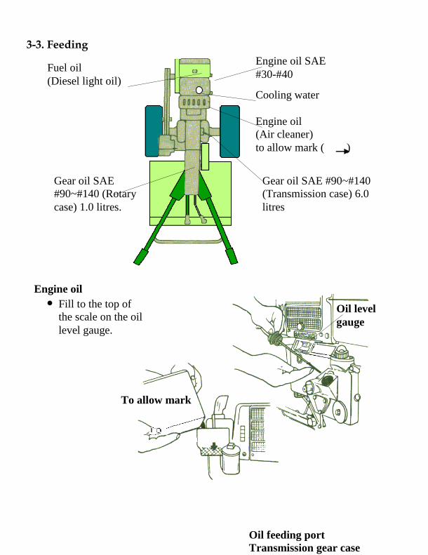
3-3. Feeding
Engine oil SAE
#30-#40
Cooling water
Engine oil
(Air cleaner)
to allow mark ( )
Fuel oil
(Diesel light oil)
Engine oil
Fill to the top of
the scale on the oil
level gauge.
To allow mark
Oil level
gauge
Oil feeding port
Transmission gear case
Gear oil SAE #90 ~ # 140
Gear oil SAE #90~#140
(Transmission case) 6.0
litres
Gear oil SAE
#90~#140 (Rotary
case) 1.0 litres.

Gear oil
Rotary case
Gear Oil SAE
#90~#140
1.0 litres
Grease
Side chain case

Cooling water Pour the water into the top till it overflows. 3-4. Fitting of rotary tines When fitting of the tine is completed, stop the engine and set the rotary change lever to the " N " position. 1) Arrangement of Inner Rotary Tines
Outer Tines Outer Tines Inner Tine
Round cut
mark
Red painted
Rotary bracket fixing bolt
Use of clean water
O : Tine Tip outward (red -painted tine )
1 : Tine Tip inward (yellow-painted tine)
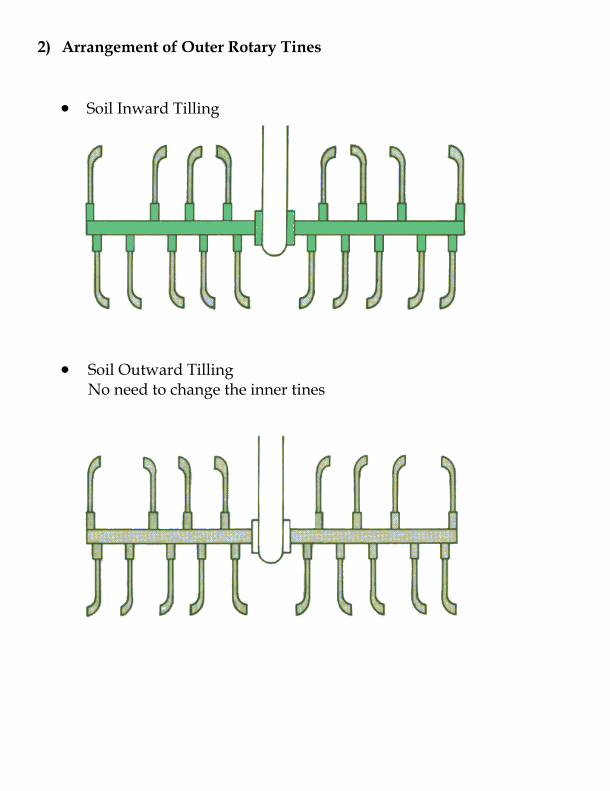
2) Arrangement of Outer Rotary Tines
Soil Inward Tilling
Soil Outward Tilling No need to change the inner tines
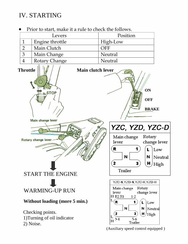
IV. STARTING
Prior to start, make it a rule to check the follows.
Levers Position
1 Engine throttle High-Low
2 Main Clutch OFF
3 Main Change Neutral
4 Rotary Change Neutral
START THE ENGINE
WARMING-UP RUN
Without loading (more 5 min.)
Checking points.
1)Turning of oil indicator
2) Noise.
(Auxiliary speed control equipped )
ON
OFF
BRAKE
Main clutch lever Throttle

V. OPERATION Select the most suitable position for your soil and working condition.
No Contents Position
YZC,YCD, YZC - D
YZCN/H
1 Main change lever Forward 1- 3 Reverse 1
Forward 1- 6 Reverse 1- 2
2 Rotary change lever Low or Hight
3 Side chain case Large or Small
4 Tail wheel adjusting handle & lever Shallow - Deep
5 Rotary Tine Inward or Outward
6 Tread (mm) 6-12 or 5.00-12 (526.708 or 546.688), 2 stage
7 Stand lever Up
1) Main change lever
Auxiliary speed control lever
(Available for - Model YZC-N/H only) 2) Rotary change
lever 3) Side chain
Case
High
Low
Auxiliary speed control lever
(Available for Model YZC-N/H only)
UP
UP SMALL SOIL
LARGE SOIL *Use auxiliary speed control
lever for switching H-L

4) Tail wheel adjusting handle & lever
The adjustment of tilling depth can be done by low-ering or raising the tail wheel by means of the ad-justing handle and the tightening handle.
5) Rotary tine (see page 8) Deep TILLING DEPTH Shallow Notice :
1. Pay attention to the driving with 3rd forward speeds since they are high speed. (On YZC-N ,5 and 6 are high speed positions).
2. When driving downhill, apply the side clutch to opposite to the side to which the tiller tends to curve.
3. Lighting system.
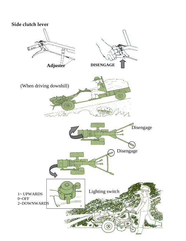
Side clutch lever
DISENGAGE
Adjuster
(When driving downhill)
Disengage
Disengage
Lighting switch 1~ UPWARDS
0~OFF
2~DOWNWARDS
VI. ADJUSTMENTS
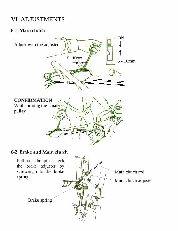
6-1. Main clutch
6-2. Brake and Main clutch
Adjust with the adjuster
5 - 10mm
ON
5 - 10mm
CONFIRMATION
While turning the main
pulley
Main clutch adjuster
Brake spring
Pull out the pin, check
the brake adjuster by
screwing into the brake
spring. Main clutch rod
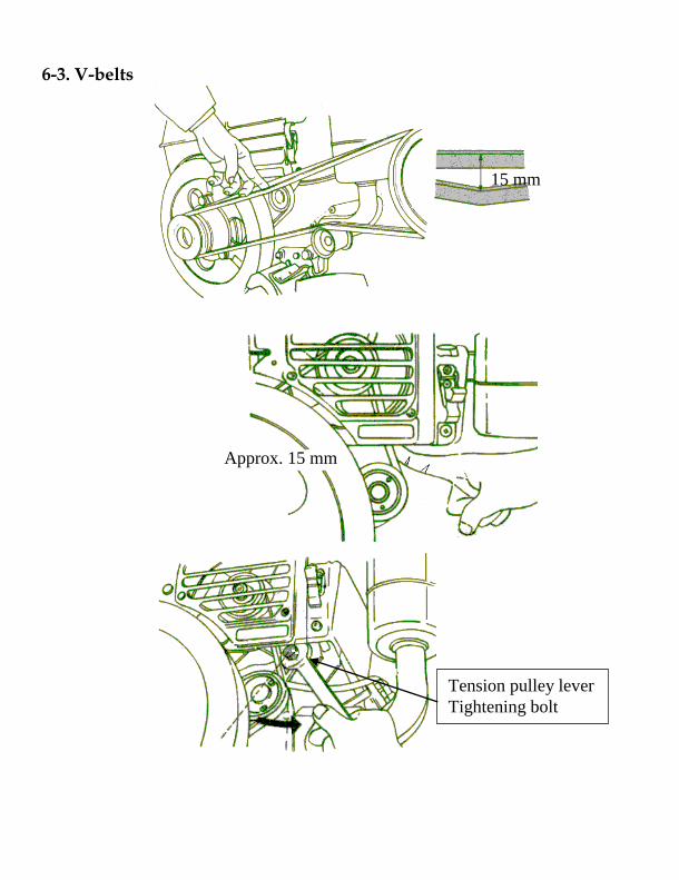
6-3. V-belts
15 mm
Approx. 15 mm
Tension pulley lever
Tightening bolt

6-4. Side Clutches 6-5. Tread
Wheel flange
6-12Tire
(5.00-12 Tire ) (546) (688)
Side Clutch Cable Adjuster
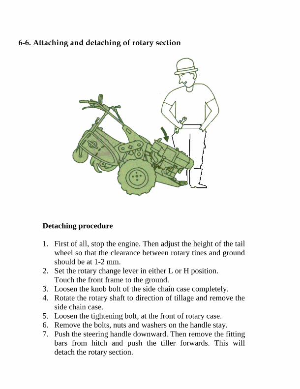
6-6. Attaching and detaching of rotary section
Detaching procedure
1. First of all, stop the engine. Then adjust the height of the tail
wheel so that the clearance between rotary tines and ground
should be at 1-2 mm.
2. Set the rotary change lever in either L or H position.
Touch the front frame to the ground.
3. Loosen the knob bolt of the side chain case completely.
4. Rotate the rotary shaft to direction of tillage and remove the
side chain case.
5. Loosen the tightening bolt, at the front of rotary case.
6. Remove the bolts, nuts and washers on the handle stay.
7. Push the steering handle downward. Then remove the fitting
bars from hitch and push the tiller forwards. This will
detach the rotary section.
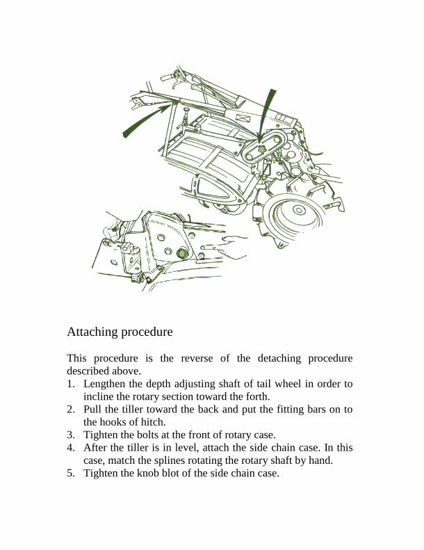
Attaching procedure
This procedure is the reverse of the detaching procedure
described above.
1. Lengthen the depth adjusting shaft of tail wheel in order to
incline the rotary section toward the forth.
2. Pull the tiller toward the back and put the fitting bars on to
the hooks of hitch.
3. Tighten the bolts at the front of rotary case.
4. After the tiller is in level, attach the side chain case. In this
case, match the splines rotating the rotary shaft by hand.
5. Tighten the knob blot of the side chain case.
VII. AFTER OPERATION
7-1. Stopping
Post operation maintenance greatly life of the tiller
Contens Procedure Remarks
Throttle lever Stop Do not use the
decompression lever
Main clutch lever OFF
Main change lever Neutral
Rotary change lever Neutral
Stand Put down
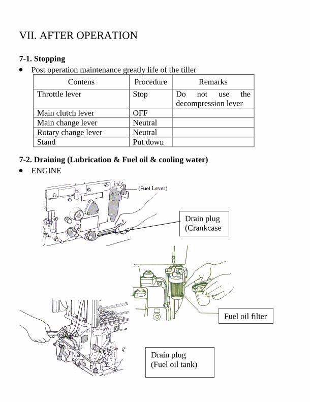
7-2. Draining (Lubrication & Fuel oil & cooling water)
ENGINE
Drain plug
(Crankcase
)
Drain plug
(Fuel oil tank)
Fuel oil filter
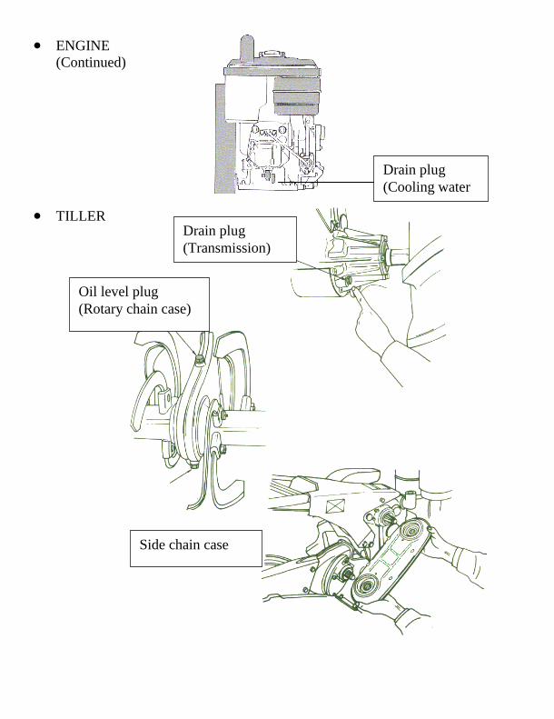
ENGINE
(Continued)
TILLER
Drain plug
(Cooling water
Drain plug
(Transmission)
Oil level plug
(Rotary chain case)
Side chain case
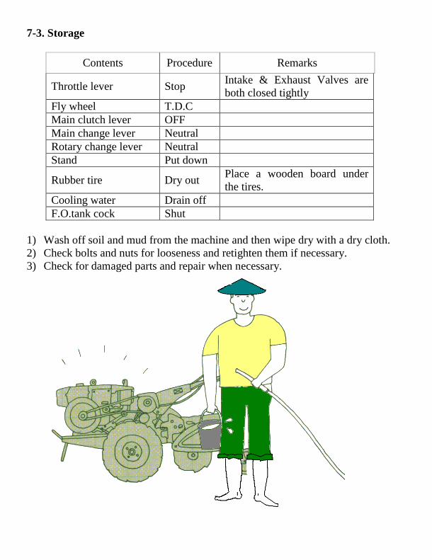
7-3. Storage
Contents Procedure Remarks
Throttle lever Stop Intake & Exhaust Valves are
both closed tightly
Fly wheel T.D.C
Main clutch lever OFF
Main change lever Neutral
Rotary change lever Neutral
Stand Put down
Rubber tire Dry out Place a wooden board under
the tires.
Cooling water Drain off
F.O.tank cock Shut
1) Wash off soil and mud from the machine and then wipe dry with a dry cloth.
2) Check bolts and nuts for looseness and retighten them if necessary.
3) Check for damaged parts and repair when necessary.

VIII. MAINTENANCE
8-1. Engine
Description Daily
Every
100
Hrs
Every
200
Hrs
Every
300
Hrs
Remark
Cooling
Water Checking and feeding
Fuel oil
Checking and feeding
Changing (F.O.tank)
F.O.inlet strainer
cleaning
F.O.outlet strainer
cleaning
Lubricati-
on Oil
Checking and feeding
L.O.intake filter
Checking and feeding
(Crankcase, Air cleaner)
Cleaning of air cleaner
element
Cleaning of oil
circulation indicator
Changing (Crankcase)
Cooling
fan belt Checking and tightening
Others
Checking and tightening
(Major parts)
Adjusting intake &
exhaust valves clearence
Checking
(Fuel injection system)
Should be cleaned often according to the degree of dust deposit.
Renew the lubricating oil of the crank case after first 25 Hrs of Service.
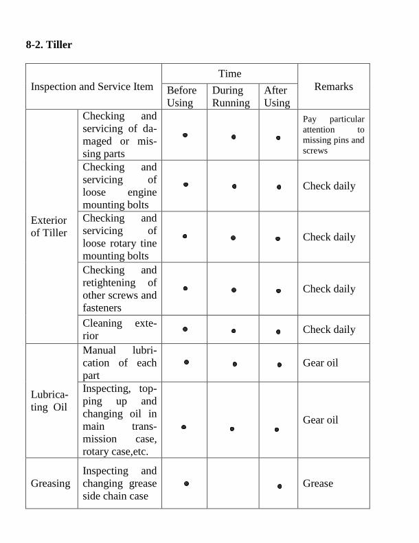
8-2. Tiller
Inspection and Service Item
Time
Remarks Before
Using
During
Running
After
Using
Exterior
of Tiller
Checking and
servicing of da-
maged or mis-
sing parts
Pay particular
attention to
missing pins and
screws
Checking and
servicing of
loose engine
mounting bolts
Check daily
Checking and
servicing of
loose rotary tine
mounting bolts
Check daily
Checking and
retightening of
other screws and
fasteners
Check daily
Cleaning exte-
rior
Check daily
Lubrica-
ting Oil
Manual lubri-
cation of each
part
Gear oil
Inspecting, top-
ping up and
changing oil in
main trans-
mission case,
rotary case,etc.
Gear oil
Greasing
Inspecting and
changing grease
side chain case
Grease
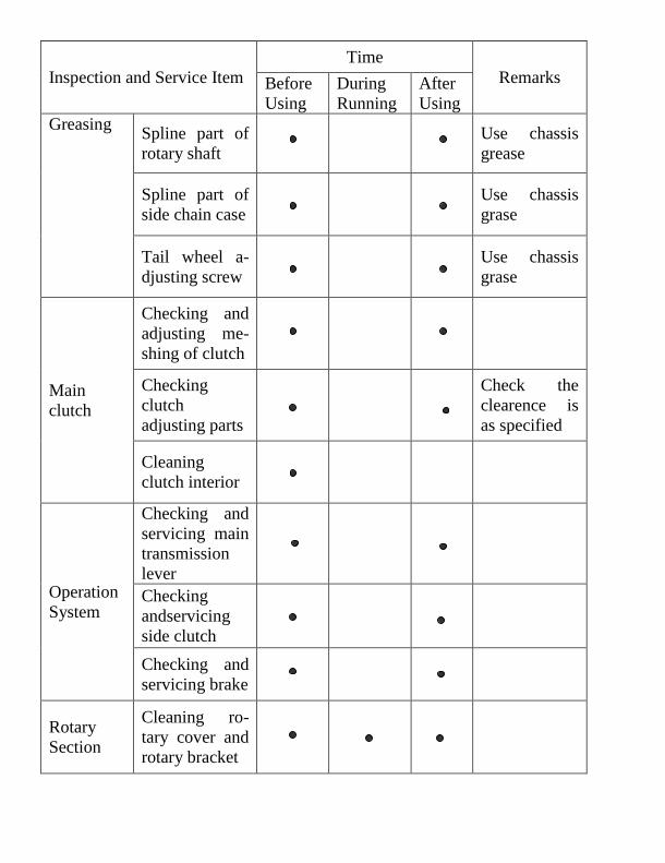
Inspection and Service Item
Time
Remarks Before
Using
During
Running
After
Using
Greasing Spline part of
rotary shaft
Use chassis
grease
Spline part of
side chain case
Use chassis
grase
Tail wheel a-
djusting screw
Use chassis
grase
Main
clutch
Checking and
adjusting me-
shing of clutch
Checking
clutch
adjusting parts
Check the
clearence is
as specified
Cleaning
clutch interior
Operation
System
Checking and
servicing main
transmission
lever
Checking
andservicing
side clutch
Checking and
servicing brake
Rotary
Section
Cleaning ro-
tary cover and
rotary bracket
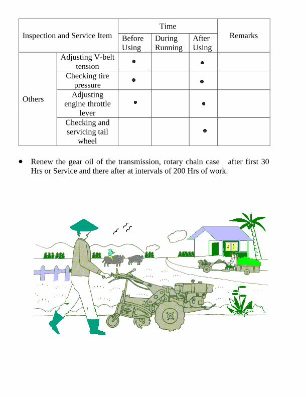
Inspection and Service Item
Time
Remarks Before
Using
During
Running
After
Using
Others
Adjusting V-belt
tension
Checking tire
pressure
Adjusting
engine throttle
lever
Checking and
servicing tail
wheel
Renew the gear oil of the transmission, rotary chain case after first 30
Hrs or Service and there after at intervals of 200 Hrs of work.
