ii71.4.:5a:ciiihgki.::::::ogi6itta:,..4:14:4q64:*v'3vn/vnc 3 76 discharge pressures cast iron...
TRANSCRIPT

.±
ii71.4.:5A:ciiihgki.::::::O
gi6itta:,..4:14:4q64:*V'
I 4 114ii''

This type of pump represents an entirely new concept in centrifugal pump design. Now a rugged centrifugal pump is commercially available as an "in-line" pump for general or any specific service. The INLINER, with pull-from-the-casing design, is a unique departure from standard pump construction and provides advantages that result in lower installation cost, decreased maintenance charges, with maximum saving of space. INLINER pumps are flange-mounted in the piping line. They are driven by standard P-base motors and are available with standard packed box or mechanical seals. Turbine drive is available.
TYPES
The INLINER is available in coupled and non-coupled design as noted below. The letter "C" after pump model indicates the coupled version.
MATERIALS
INLINER pumps are available in various materials including all iron, all iron with bronze impeller, steel, stainless steel, all bronze and nodular iron.
APPLICATION
These pumps are designed to meet the requirements of a wide variety of services and are recom-mended for use in general industry, air conditioning, the chemical and hydrocarbon processing
industries, food industry, petroleum bulk plants, etc.
SIZES
INLINER pumps are built in discharge sizes ranging from 1 to 3 inch, in capacities up to 750 GPM,
and in varying heads up to a maximum of 520 feet. Horsepowers range from 1 1/2 to 100.
The INLINER The couple;rI INLINER
Copyright 1965 by Ingersoll-Rand Company 2 Form 70405-B 3/F/65
4
4
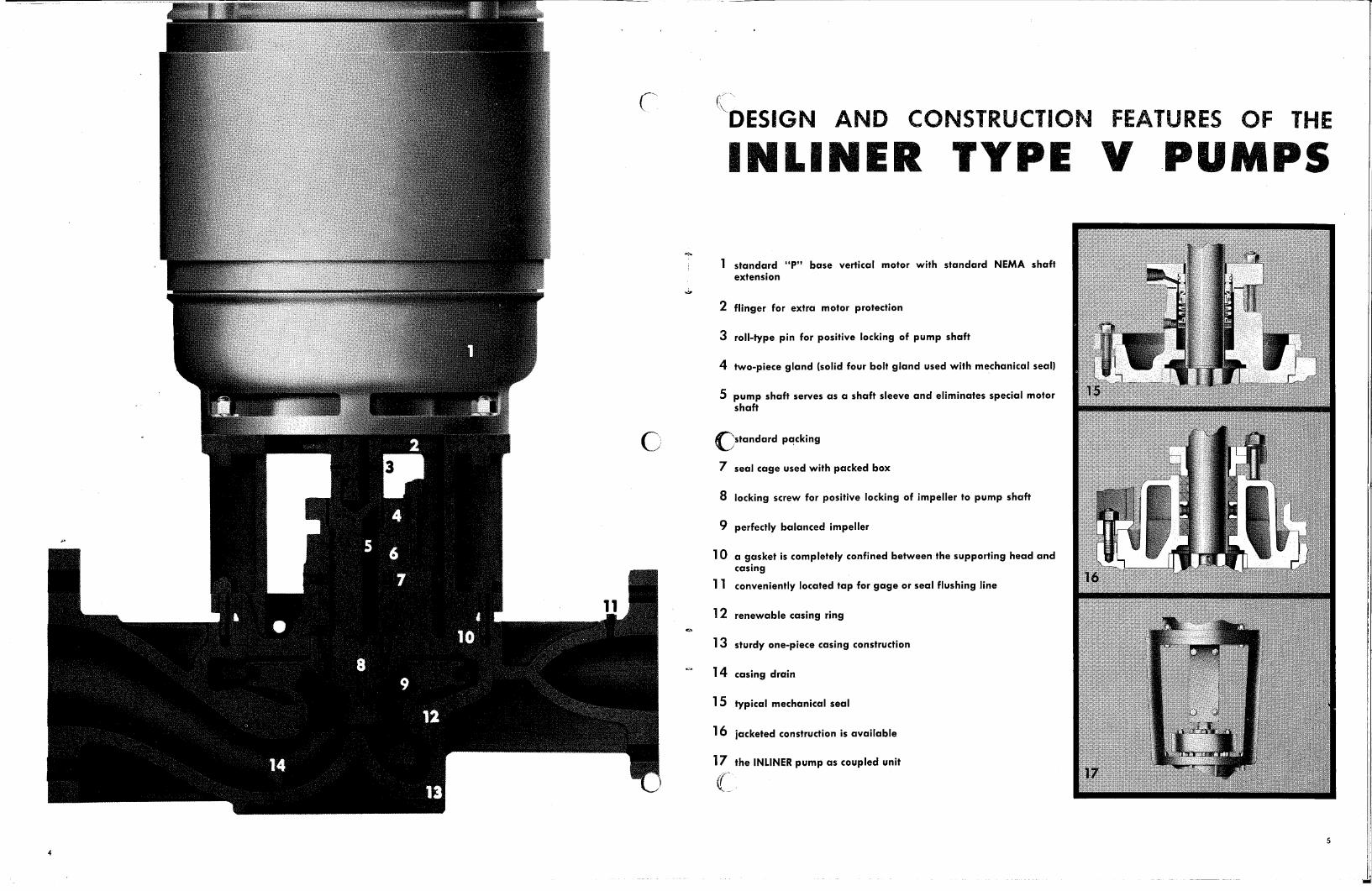
DESIGN AND CONSTRUCTION FEATURES OF THE
INLINER TYPE if PUMPS
1 standard "P" base vertical motor with standard NEMA shaft extension
2 flinger for extra motor protection
3 roll-type pin for positive locking of pump shaft
4 two-piece gland (solid four bolt gland used with mechanical seal)
5 pump shaft serves as a shaft sleeve and eliminates special motor shaft
Cstandard packing
7 seal cage used with packed box
8 locking screw for positive locking of impeller to pump shaft
9 perfectly balanced impeller
1 0 a gasket is completely confined between the supporting head and casing
11 conveniently located tap for gage or seal flushing line
12 renewable casing ring
13 sturdy one-piece casing construction
14 casing drain
15 typical mechanical seal
16 jacketed construction is available
17 the INLINER pump as coupled unit
5
NER PU
Intone
Cotip vailable
asing , !Oed For Extra Strength
pleco or three piece c:onstr uct ,A-th and
dit'etiLiroe [riterrzz al with castm fcr pull-from
LdeSiE ]s- drilledandtaPPed to provIde
for, 4:Lb land cdob t l.rction. Frovisio1 unclozzlas.'
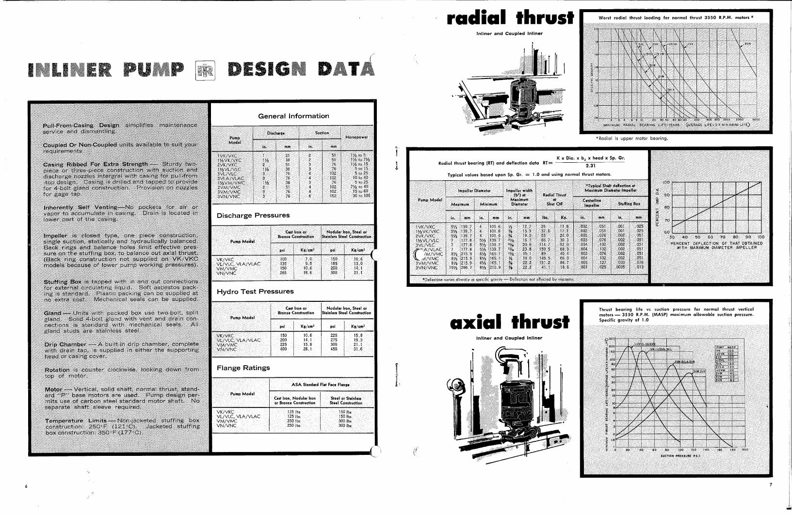
Worst radial thrust looding for normal thrust 3550 R.P otorg *
11111111 1111111111111 UiIi5M 11101 MEI
11M111.11111 11111111111111MMIIIM
is 00
MINtMIJM RADIAL GEARING L FE-YEARS ERAGE LIFE S X MFNIMLII4 LI E
Thrust bearing life vs suction pressure for normal thrust vertical motors - 3550 R.P.M. (MASP) maximum allowable suction pressure. Specific gravity of 1.0
MEM /111M11111111111111111111
. ■-‘ •
11111M1111M01112M 11111111/1111.11111.VAIIIIVAIIMA 1111111■111WAMMIIIII 111/1111111111WAIMMIIIIIMILIII
. /ANIMIIIIIIN'AILWAIII11011111111111112111M■111111
11111M2111111111111ME1111 morarAnlimmimm. crainurnmommalam■
120
200
SUCTION PRESSURE RS,I
100
60
rivic
SillM1113131ff
*Radial is upper motor bearing.
K x Dia_ x by x head x Sp. Gr. Radial thrust bearing (RT) and deflection data RT=
2.31
Typical values based upon Sp. Gr. = 1.0 and using nor al thrust motors.
,
1, Impeller Marotta Impeller width
(b2) at Radial Thrust
Maximum at Centerline Maximum Minimum Diameter Shut Off Impeller Stuffing Box
*Typical- Shaft deflection at Maximum Diameter Impeller
Pump Model
1vx/vKC 11/2VK/VKC 2VK/VKC 11/2V1../VLC 3VL/VLC
C'IA/VLAC /M/VMC
.A/VMC 3VM/VMC 3VN/VNC
radial thrust lnliner and Coupled Inliner
100
1111111111= 80
NIEMEN 60
30 40 50 60 70 80 90 100
PERCENT DEFLECTION OF THAT OBTAINED WITH MAXIMUM DIAMETER IMPELLER
90
70
4 ,101.6 1/2 1 12,7 4 1101.6 ~
15.9 '4 •
34- 19.0 51/2 139.7
16.7 51/2 139.7
20.6 51/2 139.7
"Alp 23.8
61/2 165.1
"42 15,1
61/2 165,1
34
19.0 61/2 165,1
22.2 81/2 215.9
22.2
51/2 139.7 51/2 139.7 51/2 139.7 7
177.8 7
177.8 7 1177,8
81/2 215.9 81/2 215.9 81/2 215.9
101/2 266.7
*Deflection varies directly as spec k gravity - Deflection not affected by viscosity.
axial thrust InlIner and Coupled lnliner
7
26 37,6 53 66.7 -
114.7 150.5 89
145.5 191.2 41.1
11.8 17..1 24.0 30.3 52,0 66.3 40_4 66.0 86 ..7 , 18.6
.002
.002
.003 003
.004
.004
.003
.004
.005
.001
051 051
_076 .076 .102 .102 .076 .102 .127 .025
.001
.001
.002
.002 002
.002
.002
.002
.003 .0005
.025
.025 ,051 .051 .051 .051 .051 .051 .076 .013
-'Stuffi Box is . t`apped with in and , out conneCtionb foe 4rril ,qtrOMatirig liquid. SOft.aibeStos'ryack-ng s standaed ,packing can be supr_)lieci at
no e'xtra'cost. Mechanrcal sealt '''can be Supplied.
nitg with Pa'6ked box use two-lob:It spilt $oiid.4',-Poit'igtand with Vent and.'drein
-,nections:.is standard with, Mechanical Seals All
:gland '.stOcisH0r0:' ttairqe.s.s
6
,r5.0040#,
176.i6 10p,aiii.401 . . in oWerpart of the casing. "
L.. „potTv,,i : . . ;.,i:.910..6d. :,.:1)0,,, :O.6.00,40.e.i.,!doht-tr-1 orl , 10g..10. '..,c,,009k..,tat. ica Ot.J ..:00i .:V liy.01*i.):10 I ly balanced.
r.B .C1':'• 6 rits:..1"6nd balanWiiiliEs...f . fiiiii.H'Offective ores-. .,,,,.. ' H .., ,... ,...... .... ...,,_ Ore ork.. the stuffing boX:Ht0.bAlencei.:014.t axial thrust. ..... ...:,:, .... (Back.' ..r.jpg constr - uctiOn t..1'ot 'supplied on VKNKC mode.10: .,..tecause of lower . pui-rip working pressures).
rip Cham ber r4p'charpoer,:complete OPPlied in' , eithe(the supporting
casing-cover '
Rotation .is counter clockwise , top f rhator.
Motor - Vertical, 'shOet.normal thrstand-
ard , 40"!':base.MOtOrs.are uSed:.::.r,cierfp'pesIgn. per-
rriltS .USeHof ParbOn.,steel.Standard.rnotor shaft. No separate shaft s eeve requtre
...Temperature . .,Limits= onlacketad:.,Stuffih box 25(49F. (121 9C)., 'Jatkited', stuffing
box constr ut lion: 350 9 F (177 9 C)
DESIGN D
General Information
Discharge
Suction Pump Model
1VK/VKC 1 25 2 11/2VK/VKC P12 38 2 2VK/VKC 2 . 51 3 1 1/2VLIVLC 11/2 38 3 3VL/VLC 3 76 4 3VLA/VLA,C 3 76 4 P/2VM/VMC , 11/2 38 3 2VM/VMC 2 51 4 3VM/VMC •3 76 3VN/VNC 3 76
Discharge Pressures
Cast Iron or
Nodular Iron, Steel or Bronze Construction
Stainless Steel Construction
Pump Model
psi
Kg/cm 2
psi Kg/cm 2
VK/VKC
100
7.0
150 10.6 VL/VLC, VLA/VLAC
135
9.5
185 13.0 VM/VMC
150
10.6
200 14.1 VN/VNC
265
18.6
300 21.1
Hydro Test Pressures
Cast Iron or Nodular Iron, Steel or Bronze Construction Stainless Steel Construction
Pump Model
psi Kg/cm 2 psi Kg/cm2
VK/VKC
150 10.6 225 15.8 VL/VLC, VLA/VLAC
200 14.1 275 19.3
VM/VMC VN/VNC 225 15.8 300 21.1
400 28.1 450 31.6
Flange Ratings
ASA Standard Flat Face Flange
Pump Model
Cast Iron, Nodular Iron
Steel or Stainless
or Bronze Construction
Steel Construction
VK/VKC
125 lbs
150 lbs VL/VLC, VLA/VLAC
125 lbs
150 lbs VM/VMC
250 lbs
300 lbs VN/VNC
250 lbs
300 lbs
Horsepower
51 11/2 to 5 51 11/2 to 71/2 76 I 11/2 to 15 76 5 to 15
102 5 to 25 102 10 to 40 76 5 to 25
102 71/2 to 40 102 15 to 60 152 30 to 100

2880 RPM -50 cycle
.100H 20
IIINIM1111■21.111M11111•11
•EMEMPAMME 11111111111111M1 3,111111
urniw M11111111111111 7111111.MJIVAIN
AIIII Amiumurill
0-vg EEN••••.• 4/. MEM TiMe_1111311111/ 1111* MINIMA
Ping11111111 .11tem Aimi■ A ••■■=111NIMEN111111=111111111 MEMOMMEK. 1711=1111111111111111=1101
5 6 7 69 10 15 20 30 40
CUS1C METERS PER HOUR
50 60 70 80 90 100 150
15 20 25 30 40 50 60 70 80 90 100 150 200 250 300 400 500 560 US, GALLONS PER MINUTE
10 15 20 25 30 40 50 60 70 80 90 100 150 200 250 301 400 500 IMPERIAL GALLONS PER MINUTE -
MO 90 80
70
30
250.
200r 60
50
1- 40
- 30 10 < 9 m 8 25
20
15
10 9 8
30
2
1.11.JER TYPE V C VERA GE
15 20 25 30 40 50 200 250 300 05 Get IM 045 PEit S 1 UO1 111 400 600 6D° TOO 8000VOM
'18811811111Fekelle.
3550 RPM - 60 cycle
11111■._ ,mmiummm■=surowimudwhi=mmi ■111111i1111=1 EWINEN111111111M11111111Mill
MEN/1111/11. ELM 11 11111111MIKEINUILYAM
INLINER
COUPLED INLINER
APPROXI. ATE DL ENSIONS iD (EIGHTS OF INLI ER TYPE V
PUrTS Pump Model H.P.
DIMENSIONS ' . !Miner Coupkc1
Wine/ Weight Weight
m in. mm in. mm In. mm Lbs. Kg. Lbs. Kg.
1VK/VKC 13/4 2 3 5
14 356 I 8 I
253/4 I 638 203 253/4 638
253/4 638 I 303/4 765
313/4 313/4 31% 363
811 160 72.6 811 I 165 74.9 811 1 165 74.9 938 205 ; 93
167 172 172 212
75.6 78 78 5. r,
1 1/2VK/VKC
11/2 2 3 151/2 5 71/2
394 81/4 210
253/44 643 25% 643 253/44 643 303/44 770 303/44 770
32.3/4, 32% 323/4 373/4 37 1,4
816 816 816 943 943
165 170 170 210 215
, 74.9 77 . 1
I 77.1 95.3 97.5
172 177 177 217 222
78 80.3 80.3 98.4 100.7
2VIC/VKC
1 1/2 2 3 5 171/2 7%
10 15
445 9 1 229 F
26 26 26 31 31
F 311/2 31 1/2
i 660 660 660 787 787 800 aoo
32'314 323/4 323/4 371 3/44 371 % 383/46 383/4,
833 833 833 960 960 973 973
170 175 175 215 220 310 340
77.1 79,4 79.4 97.5 99.8
140.6 154.2
177 182 182 222 227 317 347
80.3 82,6 82.6 100.7 103 143.8 15.4
13/4 VL/VLC 5 71/2 18 1/2 470
10 15
103/4 257 34 34 341/2 341/2
864 864 876 876
421/4 423/44 423/44 423/44
068 1068 081
1081
300 305 395 425
136 138.3 179.2 192 8
315 320 410 440
142 9 145.2 186 199,6
3V1./VL.0
5 7%
10 15 20 25
21½ 546 103/4 273
I
F 343/44 34% 341 3/44 341 3/44 373/44 3754
875 875 888 888 955 955
421/2 42 1/2 43
I 43 453/4 453/4
080 080 092 092
1159 1159
325 330 420 450 515 540
147.4 149.7 190.5 204 233.6 244.9
340 345 435 465 530 555
154.2 156.5 1973, 210.9 240.4 251.7
11/2 -vtv1 vtoc
5 71/2 10 1520 25
21 534 F
I 11% F 292
343/4 34% 34% 343/4 371/4 371/4
867 867 880 880 947 947
423/44 42% 42, 146 421% 45% 45%
072 072 F 084 084
1151 151
340 345 435 465 530 555
154.2 156.5 197.3 210.9 240.4 251.7
355 360 450 480 545 570
161 163.3 204.1 217.7 247.2 258.6
2VM/VMC
7% 10 15 20 25 30 40
22 I
559 12 305
343/4 353/46 35% 383/44 383/44 403/44 403/44
888 901 I 901 968 968
1022 1022
43 431/2 431/2 463/4 463/4 481/4 481/4 1226
092 105 05
172 72
226
365 455 485 550 575 665 715
165.6 206.4 220 249.5 260.8 301.6 324.3
380 470 500 565 590 680 730
172.4 213.2 226.8 256,3 267.6 308.4 331.1
3VM/VMC
15 20 25 30 40 50 60
24 601 F 123/4 321
351/2 902 383/4 969 381/4 969 401/4 1023 401/4 F 1023 42 1067 42 F 1067
433/44 463/44 463/44 483/44 483/44 503/40, 503/44
106 173 173 227 227 272
1272
500 565 I 590 680 730 900 940
226.8 256.3 267.6 308.4 331.1 408,2 426.4
515 580 605 695 745 915 955
233.6 263.1 272.4 315.3 337.9 414.6 433.2
3VLA/VLAC
10 15 20 25 30 40
23 584 111/2 292 I
351/4 351/4 373/4 373/4 40 40
895 895 962 962
1016 1016
433/44 100 433/44 100 45% I 167 453/4 I 1167 48;16 I 221 485j 1 1221
430 460 525 550
690 640 I2903
195 208.6 238.1 249.5
313
445 475 540 565 655 705,
201.8 215.5 244. 9 256.3 297.1 319.8
, /N ,VNC
30 40 50 I 60 75
100
281/2 724
1
16% 416
421/2 421/2 441/4 441/4 483/4 483/4
1080 1080 1125 1125 1236 1236
513/44 j 513/44 I 529.4 523/4 57344 573/44
297 1297 1341 341 453
1453
855 905
1075 1115 1265 1345
387.8 410,5 487.6 505,7 573.8 610,1
880 930
1100 1140 1290 1370
399.2 421.8 498.9 517.1 585.1 621,4
8 9

At work in a large chemical plant.
'An Milner on hot water circulation in a large winery.
Flexibility in mounting can be noted in this installation
near the ceiling. lrr,et is closeup of pump.
On boiler feed service in a large rnnnery —
note ease of checking on seal c - rack g.
On generol wilier serv-
ice in a power generat-
ing station.
.800
Four Irdinerb on chrinticol tronsfer service.
Installed on cooling
tower service for hot.l
air conditioning system
10 11
IV
P fEcIrPv.re :A:0P? tlfg..N.15
:MIP tlialInCel,
.N.S.'.- ..t, 2-ag.
Itgr.A.7,.... . tv-
3. ilVt::4;4" - V''' .! IL :i...gg',1.1.-
. :.....0.:k U.tc. • 'ft • L AwARA, ,! c 4,.. • i.0.101.7474,41:k..•
. v.._ A-0.-cl. •0:.icl.. •••:.tiotkarOup, ,
..th.t..n.-.7.0: :-Nry..•• :?:!Pot.AiiRi. Li.41.. • ril:gan's lq■pt! -
•
.11...:zi.::•:).(!•=: ic....?€• -: ,
i..t41N. 4 • TU..
f.10
61 Ir.rd , S.4 F'Yot rrt;
• :'•ejWit• :
•
1.1:1 ' •
'n