ii. system components autonomous robotic follower · pdf file ·...
TRANSCRIPT
Autonomous Robotic Follower
with License Plate Recognition
Capability
Khanh Le, Luis Sosa, Bryan Diaz,
Victor Salomon
Dept. of Electrical Engineering and Computer
Science, University of Central Florida, Orlando,
Florida, 32816-2450
Abstract — A computer vision based robotic follower system
implementation is presented, and this robotic following mechanism is triggered by the use of an Automatic License Plate Recognition (ALPR) algorithm. The robot is trained at
the moment of the event to use a tracking algorithm, this system tracks a lead vehicle using a sequence of images captured on video. On this paper the focus is a low cost, single
board computer implementation, simulating the functioning as closely as possible of a regular motor vehicle.
Index Terms — ALPR, Computer Vision, Autonomous Following, Single Board Computer, License Plate Recognition.
I. INTRODUCTION
As the computing technologies advance and become
more cost effective we see more of these applied to
different areas in our daily lives, one of which is the safety
of the population in general. Because of this we see
applications of computer vision such as in the case of facial
image recognition or Automatic License Plate Recognition
(ALPR). These solutions are implemented in systems used
for applications such as automatic toll payments or access
control for residential or industrial areas.
This paper proposes a different application, using a
ALPR algorithm a robot detects a license plate number, this
extracted license plate number is then compared to a
database simulating that which a law enforcement officer
would have available, if the number extracted is matched to
a license plate number which is black listed for any given
reason, the robot will train itself to follow the said license
plate. The system design is shown in Figure 1, the main
element in the system is the single board computer, a
Raspberry Pi 2 Model B, which provides a low cost
platform to perform the processing needed for the computer
vision is processed, as well as running the other processes
involved in the testing case scenario.
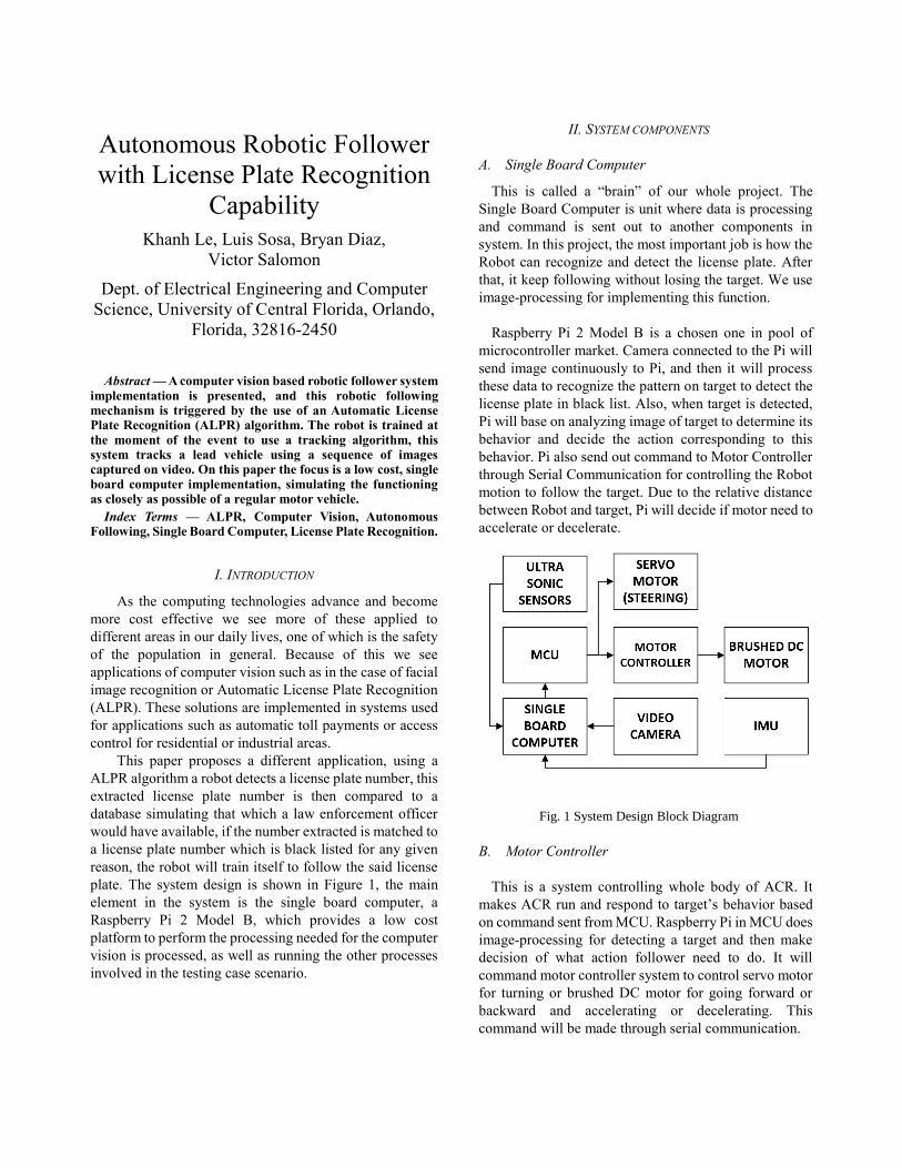
II. SYSTEM COMPONENTS
A. Single Board Computer
This is called a “brain” of our whole project. The
Single Board Computer is unit where data is processing
and command is sent out to another components in
system. In this project, the most important job is how the
Robot can recognize and detect the license plate. After
that, it keep following without losing the target. We use
image-processing for implementing this function.
Raspberry Pi 2 Model B is a chosen one in pool of
microcontroller market. Camera connected to the Pi will
send image continuously to Pi, and then it will process
these data to recognize the pattern on target to detect the
license plate in black list. Also, when target is detected,
Pi will base on analyzing image of target to determine its
behavior and decide the action corresponding to this
behavior. Pi also send out command to Motor Controller
through Serial Communication for controlling the Robot
motion to follow the target. Due to the relative distance
between Robot and target, Pi will decide if motor need to
accelerate or decelerate.
Fig. 1 System Design Block Diagram
B. Motor Controller
This is a system controlling whole body of ACR. It
makes ACR run and respond to target’s behavior based
on command sent from MCU. Raspberry Pi in MCU does
image-processing for detecting a target and then make
decision of what action follower need to do. It will
command motor controller system to control servo motor
for turning or brushed DC motor for going forward or
backward and accelerating or decelerating. This
command will be made through serial communication.

This system has its own micro-controller which is
separated from MCU, which makes designing hardware
and programming to be easier. The micro-controller
communicates with servo motor directly through I/O pins
but controls the brushed DC motor by using H-Bridge as
middle guy.
C. Ultra Sonic Sensors
This type of sensors use ultra-sonic waves to
determine a given distance. One of the biggest
advantages compared to other sensors which have similar
capabilities is that this type of sensor can be used inside
or outside building because the sunlight does not affect
its operation as it does for infrared sensors, and because
of this reason, an ultrasonic sensor is relatively more
accurate.
The ultrasonic sensor has an output which emits an
ultrasonic signal and an input which receives it after this
bounces on a surface. Based on the time passed between
signal sent out and the return echo received, the distance
can be calculated, providing a high rate of accuracy, with
ranges of operation ranging from 10cm to more than
80cm.
D. Inertia Measuring Unit (IMU)
This inertial measurement unit (IMU) is a
component of navigational equipment, and it is usually
composed by a combination of accelerometers,
gyroscopes, magnetometers and sometimes other
electrical sensors inertial measurement units can measure
orientation, acceleration rates, and rotational changes.
These are often produced in different styles with
differing levels accuracy which is measured in degrees of
freedom.
The inertial measurement unit can also be used to
measure gravitational forces which are commonly called
g-forces and by measuring the various forces and keeping
track of them, the inertial measurement unit is able to
produce a linear record of these measurements, which are
then processed and the data that results is used to
calculate the inertial measurement unit’s position based
on reported velocity, direction, and time elapsed. This
data can be directly overlaid onto an electronic mapping
system that can tell the inertial measurement unit its
location and orientation with respect to a point, which
can be useful to detect a possible accident of the motor
vehicle, adding an extra safety measure to our system.
E. Power Supply
The power supply it is a very important part of the
project. It is what gives life and energy needed for the
systems to perform effectively. If the power is not
supplied efficiently, malfunctions in the subsystem may
arise. In Figure 2, a high level diagram of the power
supply system is represented.
Fig. 2 High Level Diagram of power system
1. Main DC source
The system Main DC source consists of a rechargeable
battery. This battery is responsible of supplying enough
power for the system to work efficiently. Three different
voltage regulators will be in charge of stepping down the
voltage accordingly to the need of each load
Main Dc Source consists of a rechargeable battery.
There were several requirements needed to be taken into
account in the selection of the battery. First, the battery
must be able to last at least 30 minutes at full load. Also, it
must be small and lightweight, the latter especially
important, because the performance of the ACR car might
be affected if the weight increases. After much
consideration and research, the battery chemistry selected
for the project was the Lithium Polymer Ion battery. This
battery chemistry provides a lightweight design, with
improved safety to overcharging and has a low probability
of electrolyte leakage which can negatively affect the
performance of the battery.
2. Voltage Regulators
The second part of the power supply diagram are the
voltage regulators. There were to main technologies to be
consider for our project, linear vs switching voltage
Main DC Source
Voltage Regulator
Motor
Voltage Regulator
Raspberry Pi
Camera
Voltage Regulator
MCU
Sensors
Servo Motor
(Steering)

regulators. Table #1 shows the difference between the two
technologies.
Features Linear
Voltage
Regulator
Switching
Voltage
Regulator
Function Step down
only, output
voltage must
be less than
input voltage
Steps up or Steps
Down the
voltage, can
produce multiple
outputs.
Size Small to
medium in
portable
design, may
be even larger
if heat sink is
needed
Large than linear
at low power, but
smaller in the
case where linear
requires a heat
sink
Efficiency Low to
medium
High
Noise Low Medium to high
due to ripple
effect
Output
Ripple
Very small
almost
negligible
Large
Waste
Heat
High, when
load and
voltage
difference is
high
Low, most
components will
run cool for low
power levels
Table #1.Linear Voltage Regulator Vs Switching Voltage
Regulator
The ACR car uses switching voltage regulators. Based on
the research, switching regulators are more effective and
highly efficient, in stepping down a voltage, when the
difference between the two voltages is large. Having a high
efficient regulator is necessary in our design because our
main source of power is a battery. It is necessary that the
power supplied to the system is not wasted in the form of
heat.
III. HARDWARE DETAILS
A. Image-Processing:
We are using the raspberry Pi 2 model for image
processing. There are a number of advantages of using the
Pi which is why we chose it. It has an operating system
which makes it much easier to use for the image processing
libraries. It has multiple USBs which is good because the
camera is a USB camera, we can also connect a keyboard
and a mouse to make it easier to interact with the Pi. It also
has a HDMI port so we can connect it to a monitor and see
what’s happening. Since image processing is very
performance intense we decided to buy two heat sinks and
one little fan for the main Pi processor. With the heat sinks
and the fan we are now able to overclock the Pi to
1000MHz and 500MHz for SDRAM which would make
the image processing a little faster.
B. Motor controller system
This system is composed of MSP430, Pololu motor
driver, Brushed DC motor, servo motor and voltage
level shifter between 3.3V and 5V.
1. MSP430G2553:
We pick MSP430g2553 to be this system
controller because we are familiar to this micro-
controller during Embedded System courses. Besides
that, it has same voltage level with Raspberry Pi
which is a whole project’s brain. MSP430 is able to
communicate with Raspberry Pi through Serial Port
by connecting directly TX pin on Pi to RX pin (Pin
1.1) of MSP430.
Fig. 3: MSP430 connection.
We only use MSP430 chip, not a whole launch pad,
for this project. In order to power it without the
board, we need to connect Vcc (Pin1) and Reset
(Pin16) to 3.3V. Besides that, pin20 is required to be
connected to ground. We are not going to use all the
pins of MSP430. This table #2 below shows the pins
used for connection with another components in
system.
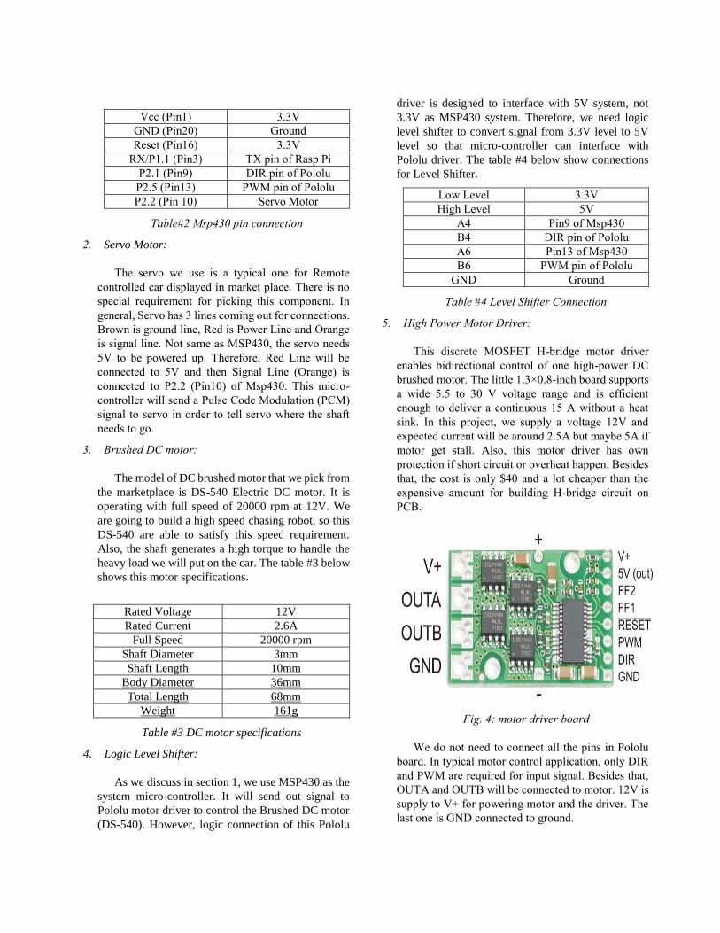
Vcc (Pin1) 3.3V
GND (Pin20) Ground
Reset (Pin16) 3.3V
RX/P1.1 (Pin3) TX pin of Rasp Pi
P2.1 (Pin9) DIR pin of Pololu
P2.5 (Pin13) PWM pin of Pololu
P2.2 (Pin 10) Servo Motor
Table#2 Msp430 pin connection
2. Servo Motor:
The servo we use is a typical one for Remote
controlled car displayed in market place. There is no
special requirement for picking this component. In
general, Servo has 3 lines coming out for connections.
Brown is ground line, Red is Power Line and Orange
is signal line. Not same as MSP430, the servo needs
5V to be powered up. Therefore, Red Line will be
connected to 5V and then Signal Line (Orange) is
connected to P2.2 (Pin10) of Msp430. This micro-
controller will send a Pulse Code Modulation (PCM)
signal to servo in order to tell servo where the shaft
needs to go.
3. Brushed DC motor:
The model of DC brushed motor that we pick from
the marketplace is DS-540 Electric DC motor. It is
operating with full speed of 20000 rpm at 12V. We
are going to build a high speed chasing robot, so this
DS-540 are able to satisfy this speed requirement.
Also, the shaft generates a high torque to handle the
heavy load we will put on the car. The table #3 below
shows this motor specifications.
Rated Voltage 12V
Rated Current 2.6A
Full Speed 20000 rpm
Shaft Diameter 3mm
Shaft Length 10mm
Body Diameter 36mm
Total Length 68mm
Weight 161g
Table #3 DC motor specifications
4. Logic Level Shifter:
As we discuss in section 1, we use MSP430 as the
system micro-controller. It will send out signal to
Pololu motor driver to control the Brushed DC motor
(DS-540). However, logic connection of this Pololu
driver is designed to interface with 5V system, not
3.3V as MSP430 system. Therefore, we need logic
level shifter to convert signal from 3.3V level to 5V
level so that micro-controller can interface with
Pololu driver. The table #4 below show connections
for Level Shifter.
Low Level 3.3V
High Level 5V
A4 Pin9 of Msp430
B4 DIR pin of Pololu
A6 Pin13 of Msp430
B6 PWM pin of Pololu
GND Ground
Table #4 Level Shifter Connection
5. High Power Motor Driver:
This discrete MOSFET H-bridge motor driver
enables bidirectional control of one high-power DC
brushed motor. The little 1.3×0.8-inch board supports
a wide 5.5 to 30 V voltage range and is efficient
enough to deliver a continuous 15 A without a heat
sink. In this project, we supply a voltage 12V and
expected current will be around 2.5A but maybe 5A if
motor get stall. Also, this motor driver has own
protection if short circuit or overheat happen. Besides
that, the cost is only $40 and a lot cheaper than the
expensive amount for building H-bridge circuit on
PCB.
Fig. 4: motor driver board
We do not need to connect all the pins in Pololu
board. In typical motor control application, only DIR
and PWM are required for input signal. Besides that,
OUTA and OUTB will be connected to motor. 12V is
supply to V+ for powering motor and the driver. The
last one is GND connected to ground.

The operation of Pololu motor driver is really
simple to understand. DIR pin is low or high, which
determine the direction of motor (backward or
forward). Also, the PWM signal input through PWM
pin will control speed of the motor.
C. Ultra Sonic Sensor
The function of the ultra-sonic sensor is to prevent any
the robot to incur in any accidents, these sensors will be
placed around the robot in strategic locations such as the
front that the sides, in Figure 5 we see the placement chosen
for the robot, the front sensor, or sensor 1 is used to avoid
crashing with any obstacles in front of the robot, such as in
the case where the robot is autonomously following a target
Fig 5. Placement of Ultrasonic Sensors
On the sides we have sensors 2 and 3, which are used to
avoid crashing to obstacles when following a target which
is turning, if an obstacle is detected the turning will be
delayed for as long as there is no longer an obstacle which
would be an issue for the presented situation.
D. Inertia Measuring Unit (IMU)
This device will be used for two functions, first
measuring the speed of the robot, and also determining
whether there robot is in a situation which requires turning
off the different components of the system. The Razor IMU
board was selected, it contains three sensors an MEMS
triple-axis gyroscope (ITG-3200), triple-axis accelerometer
(ADXL345), and a triple-axis digital magnetometer
(HMC5883L), and this provides us with up to nine (9)
degrees of freedom. This board also has an MCU on-board,
an Atmel ATmega328 MCU, which will perform will
perform the processing related to the IMU.
Because the accelerometer in the IMU measures
acceleration and not speed a calculation to in order
determine such parameter is needed. In order to get speed,
the acceleration data has to be integrated over time, and
since this device is operating the discrete domain, an
approximation can be made and can be related by the
following equation where ‘a’ is acceleration, ‘V’ is
velocity, and ‘T’ is the sampling period.
V[n+1] = V[n] + T*a[n] (1)
Every time the data is sampled equation (1) will be
evaluated, and thus the velocity at the given time will be
evaluated and potentially displayed. Because of the nature
of this device, it important to note that the orientation in
which the IMU with respect to the vehicle, another factor is
also that the device is electromagnetic fields, so the IMU
must be placed away from certain components such as the
motors, as they might cause interference with the
magnetometer on board.
E. Power Supply
In order to design an effective power supply certain
parameters must be met for the effective design of the
system.
This table #5 provides the specific power values the
power supply system must supply, in order to provide
each subsystem the power needed to effectively work.
Items Input Voltage
(volts)
Input
current (A)
Raspberry Pi 5 2
Msp430 3.3 0.5e-3
Motor 3.6-12 Up to 6 amps
Servo ( Steering) 5 0.500
(2) Sensors 5 0.500
IMU 3.3 .215
Table #5: Voltage required for each component
1. Main DC Source:
The rechargeable battery selected to power the system
is a 14.8 Volts Lithium Polymer Ion battery. The battery
provides 5000mAh with a maximum discharge rate of 125
Amps. It only has 4 small cells, making the battery
lightweight and efficient.
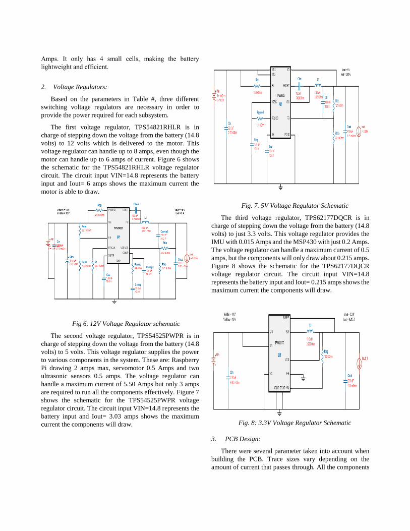
2. Voltage Regulators:
Based on the parameters in Table #, three different
switching voltage regulators are necessary in order to
provide the power required for each subsystem.
The first voltage regulator, TPS54821RHLR is in
charge of stepping down the voltage from the battery (14.8
volts) to 12 volts which is delivered to the motor. This
voltage regulator can handle up to 8 amps, even though the
motor can handle up to 6 amps of current. Figure 6 shows
the schematic for the TPS54821RHLR voltage regulator
circuit. The circuit input VIN=14.8 represents the battery
input and Iout= 6 amps shows the maximum current the
motor is able to draw.
Fig 6. 12V Voltage Regulator schematic
The second voltage regulator, TPS54525PWPR is in
charge of stepping down the voltage from the battery (14.8
volts) to 5 volts. This voltage regulator supplies the power
to various components in the system. These are: Raspberry
Pi drawing 2 amps max, servomotor 0.5 Amps and two
ultrasonic sensors 0.5 amps. The voltage regulator can
handle a maximum current of 5.50 Amps but only 3 amps
are required to run all the components effectively. Figure 7
shows the schematic for the TPS54525PWPR voltage
regulator circuit. The circuit input VIN=14.8 represents the
battery input and Iout= 3.03 amps shows the maximum
current the components will draw.
Fig. 7. 5V Voltage Regulator Schematic
The third voltage regulator, TPS62177DQCR is in
charge of stepping down the voltage from the battery (14.8
volts) to just 3.3 volts. This voltage regulator provides the
IMU with 0.015 Amps and the MSP430 with just 0.2 Amps.
The voltage regulator can handle a maximum current of 0.5
amps, but the components will only draw about 0.215 amps.
Figure 8 shows the schematic for the TPS62177DQCR
voltage regulator circuit. The circuit input VIN=14.8
represents the battery input and Iout= 0.215 amps shows the
maximum current the components will draw.
Fig. 8: 3.3V Voltage Regulator Schematic
3. PCB Design:
There were several parameter taken into account when
building the PCB. Trace sizes vary depending on the
amount of current that passes through. All the components
in the PCB are surface mount. Sizes of each components
vary from 402mm to 805mm.
F. Double-side plated through hole
This board is used for professional and secure purpose.
Our project has three different board for each function of
operation, but they are required to put on same platform for
organizing. Moreover, this is high speed chasing car, so all
connections need to be secured when moving fast. We will
put all the pins needed for connection to this board and do
soldering. Therefore, there is no wire connection will be
loose when the following car is chasing the target, even if
the collision happens.
IV. SOFTWARE DETAILS
For the software we are using different libraries to
detect a license plate and be able to track it. For the tracking
library we are using OpenCV version 2.9.10 which is one
of the best open source libraries for computer vision in the
internet. For detecting the license plate letters we use a
library called OpenALPR which has as dependency
Leptonica and Tesseract-OCR libraries. The Leptonica
library is used to do image manipulations like rotation,
scaling, convolution, grayscale morphology, etc. tesseract-
ocr is the one in charge of character recognition which it
does with the help of Leptonica. OpenALPR which is the
main library that we are using, goes thru multiple steps to
finally detect the license plate. The first phase is detection
which happens only once for each image. This uses the LBP
algorithm (which is generally used for face detection) to
find the possible license plate regions (x, y, width, height).
Once the region (or regions in the case of multiple license
plates on the same image) is detected it goes to the later
pipeline phases for further processing. The detection phase
is usually the most processing-intensive phase. Next in the
pipeline is binarization which creates multiple binary
images for each plate region. Multiple images are used
because it gives the best possible chance of finding all the
characters. If we just take a single binary image then we
may miss characters if the image is too dark or too light for
example. Next we have the character analysis phase which
attempts to find character-sized regions in the pate region.
It does this by first finding all connected blobs in the license
plate region. Then it looks for blobs that are roughly the
width and height of a license plate character and have
tops/bottoms that are in a straight line with other blobs of
similar width/height. This is done multiple times in the
region. It starts by looking for small characters then
gradually looks for larger characters. The next phase is the
one that finds the edges of the license plate. The next phase
is deskew which is use to eliminate any rotation or skew in
the image. After all that comes the character segmentation
phase which tries to isolate all the characters that make up
the plate image and then the OCR analyzes each character
independently and computes all possible characters and
their confidences.
After the OpenALPR detects a license plate it will pass
the coordinates to Consensus-based Matching and Tracking
of Keypoints algorithm (written by Nebehay Georg and
Pflugfelder Roman) so that the card could track the license
plate while the cars are in motion. This algorithm works by
breaking down the object of interest into tiny parts, known
as keypoints. In each frame the algorithm tries to find those
keypoints that were already there in the initial selection of
the object of interest.
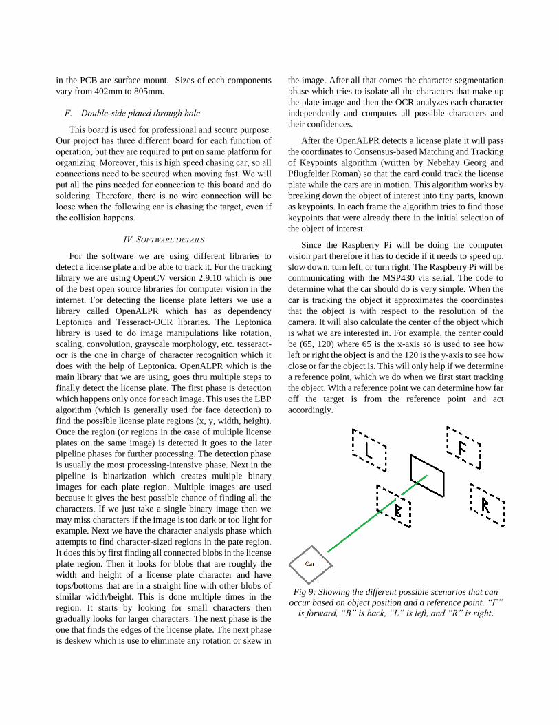
Since the Raspberry Pi will be doing the computer
vision part therefore it has to decide if it needs to speed up,
slow down, turn left, or turn right. The Raspberry Pi will be
communicating with the MSP430 via serial. The code to
determine what the car should do is very simple. When the
car is tracking the object it approximates the coordinates
that the object is with respect to the resolution of the
camera. It will also calculate the center of the object which
is what we are interested in. For example, the center could
be (65, 120) where 65 is the x-axis so is used to see how
left or right the object is and the 120 is the y-axis to see how
close or far the object is. This will only help if we determine
a reference point, which we do when we first start tracking
the object. With a reference point we can determine how far
off the target is from the reference point and act
accordingly.
Fig 9: Showing the different possible scenarios that can
occur based on object position and a reference point. “F”
is forward, “B” is back, “L” is left, and “R” is right.
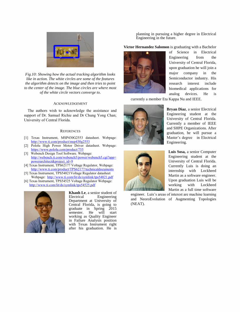
Fig.10: Showing how the actual tracking algorithm looks
like in action. The white circles are some of the features
the algorithm detects on the image and then tries to point
to the center of the image. The blue circles are where most
of the white circle vectors converge to.
ACKNOWLEDGEMENT
The authors wish to acknowledge the assistance and
support of Dr. Samuel Richie and Dr Chung Yong Chan;
University of Central Florida.
REFERENCES
[1] Texas Instrument, MSP430G2553 datasheet. Webpage: http://www.ti.com/product/msp430g2553
[2] Pololu High Power Motor Driver datasheet. Webpage: https://www.pololu.com/product/755
[3] Webench Design Tool Software. Webpage: http://webench.ti.com/webench5/power/webench5.cgi?app=powerarchitect&project_id=9
[4] Texas Instrument, TPS62177 Voltage Regulator, Webpage: http://www.ti.com/product/TPS62177/technicaldocuments
[5] Texas Instrument, TPS54821Voltage Regulator datasheet Webpage: http://www.ti.com/lit/ds/symlink/tps54821.pdf
[6] Texas Instrument, TPS54525 Voltage Regulator Webpage: http://www.ti.com/lit/ds/symlink/tps54525.pdf
Khanh Le, a senior student of Electrical Engineering Department at University of Central Florida, is going to graduate in Spring 2015 semester. He will start working as Quality Engineer in Failure Analysis position with Texas Instrument right after his graduation. He is
planning in pursuing a higher degree in Electrical Engineering in the future.
Victor Hernandez Salomon is graduating with a Bachelor
of Science in Electrical
Engineering from the
University of Central Florida,
upon graduation he will join a
major company in the
Semiconductor industry. His
research interest include
biomedical applications for
analog devices. He is
currently a member Eta Kappa Nu and IEEE.
Bryan Diaz, a senior Electrical
Engineering student at the
University of Central Florida.
Currently a member of IEEE
and SHPE Organizations. After
graduation, he will pursue a
Master’s degree in Electrical
Engineering.
Luis Sosa, a senior Computer
Engineering student at the
University of Central Florida.
Currently Luis is doing an
internship with Lockheed
Martin as a software engineer.
Upon graduation Luis will be
working with Lockheed
Martin as a full time software
engineer. Luis’s areas of interest are machine learning
and NeoroEvolution of Augmenting Topologies
(NEAT).