ihe radiology (rad) technical framework volume 1 ihe rad tf-1
TRANSCRIPT
Copyright © 2018: IHE International, Inc.
Integrating the Healthcare Enterprise
IHE Radiology (RAD) 5
Technical Framework
Volume 1 10
IHE RAD TF-1 Integration Profiles
15
Revision 17.0 – Final Text 20
July 27, 2018
Please verify you have the most recent version of this document, which is published here. 25
IHE Radiology Technical Framework, Volume 1 (RAD TF-1): Integration Profiles ______________________________________________________________________________
____________________________________________________________________________ 2
Rev. 17.0 – Final Text 2018-07-27 Copyright © 2018: IHE International, Inc.
CONTENTS 1 Introduction .............................................................................................................................. 11 30
1.1 Overview of Technical Framework .................................................................................. 11 1.2 Overview of Volume 1...................................................................................................... 12 1.3 Audience ........................................................................................................................... 12 1.4 Relationship to Standards ................................................................................................. 12 1.5 Relationship to Real-world Architectures ......................................................................... 13 35 1.6 Conventions ...................................................................................................................... 14
1.6.1 Actor and Transaction Diagrams and Tables ............................................................. 14 1.6.2 Process Flow Diagrams ............................................................................................. 14 1.6.3 Normative versus informative contents of the Technical Framework ....................... 15 1.6.4 Technical Framework Referencing ............................................................................ 15 40
1.7 Scope Additions for 2016 – 2017 ..................................................................................... 15 1.8 Comments ......................................................................................................................... 15 1.9 Copyright Permission........................................................................................................ 16 1.10 IHE Radiology Technical Framework Development and Maintenance Process .............. 16
2 Integration Profiles ................................................................................................................... 20 45 2.1 Integration Profiles Overview ........................................................................................... 25
2.1.1 Scheduled Workflow (SWF) ..................................................................................... 26 2.1.2 Patient Information Reconciliation (PIR) .................................................................. 26 2.1.3 Consistent Presentation of Images (CPI) ................................................................... 26 2.1.4 Presentation of Grouped Procedures (PGP) .............................................................. 26 50 2.1.5 Access to Radiology Information (ARI) .................................................................... 27 2.1.6 Key Image Note (KIN) .............................................................................................. 27 2.1.7 Simple Image and Numeric Report (SINR) ............................................................... 27 2.1.8 Basic Security (SEC) - DEPRECATED .................................................................... 27 2.1.9 Charge Posting (CHG) ............................................................................................... 27 55 2.1.10 Post-Processing Workflow (PWF) ..................................................................... 28 2.1.11 Reporting Workflow (RWF) .............................................................................. 28 2.1.12 Evidence Documents (ED) ................................................................................. 28 2.1.13 Portable Data for Imaging (PDI) ........................................................................ 28 2.1.14 NM Image (NMI) ............................................................................................... 28 60 2.1.15 Teaching File and Clinical Trial Export (TCE) .................................................. 29 2.1.16 Cross-Enterprise Document Sharing for Imaging (XDS-I.b) ............................. 29 2.1.17 Mammography Image (MAMMO) .................................................................... 29 2.1.18 Image Fusion (FUS) ........................................................................................... 29 2.1.19 Import Reconciliation Workflow (IRWF) .......................................................... 29 65 2.1.20 Radiation Exposure Monitoring (REM) ............................................................. 30 2.1.21 Mammography Acquisition Workflow (MAWF) .............................................. 30 2.1.22 MR Diffusion Imaging (DIFF) ........................................................................... 30 2.1.23 CT/MR Perfusion Imaging with Contrast (PERF) ............................................. 30 2.1.24 Basic Image Review (BIR) ................................................................................. 30 70
IHE Radiology Technical Framework, Volume 1 (RAD TF-1): Integration Profiles ______________________________________________________________________________
____________________________________________________________________________ 3
Rev. 17.0 – Final Text 2018-07-27 Copyright © 2018: IHE International, Inc.
2.1.25 Chest X-Ray CAD Display (CXCAD) ............................................................... 30 2.1.26 Imaging Object Change Management (IOCM) .................................................. 30 2.1.27 Cross-Community Access for Imaging (XCA-I) ............................................... 31 2.1.28 Post Acquisition Workflow (PAWF) ................................................................. 31 2.1.29 Cross-Enterprise Reliable Document Interchange – Imaging (XDR-I) ............. 31 75 2.1.30 Stereotactic Mammography Image (SMI) .......................................................... 31 2.1.31 Management of Radiology Report Templates (MRRT) ..................................... 31 2.1.32 Scheduled Workflow.b (SWF.b) ........................................................................ 31 2.1.33 Invoke Image Display (IID) ............................................................................... 31 2.1.34 Intentionally Left Blank ..................................................................................... 31 80 2.1.35 Digital Breast Tomosynthesis (DBT) ................................................................. 31 2.1.36 Web-based Image Capture (WIC) ...................................................................... 32 2.1.37 Clinical Decision Support – Order Accountable Tracking (CDS-OAT) ............ 32 2.1.38 Radiation Exposure Monitoring – Nuclear Medicine (REM-NM) .................... 32 2.1.39 Cross-Enterprise Remote Read Workflow Definition (XRR-WD) .................... 32 85 2.1.40 Intentionally Left Blank ..................................................................................... 32 2.1.41 Standardized Operational Log Events (SOLE) .................................................. 32 2.1.42 Management of Acquisition Protocols (MAP) ................................................... 32 2.1.43 Results Distribution (RD) ................................................................................... 32
2.2 Options to other Domains’ Profiles .................................................................................. 32 90 2.2.1 ITI-Audit Trail and Node Authentication .................................................................. 32
2.3 Actor Descriptions ............................................................................................................ 33 2.4 Transaction Descriptions .................................................................................................. 36 2.5 Product Implementations .................................................................................................. 40
3 Scheduled Workflow (SWF) .................................................................................................... 44 95 3.1 Actors/Transactions .......................................................................................................... 45 3.2 Scheduled Workflow Integration Profile Options ............................................................ 47
3.2.1 HL7 v2.5.1 Option ..................................................................................................... 49 3.3 Scheduled Workflow Process Flow .................................................................................. 49
3.3.1 Administrative and Procedure Performance Process Flow ....................................... 49 100 3.3.2 Patient Update Flow .................................................................................................. 52 3.3.3 Order Change Flow .................................................................................................... 55 3.3.4 Exception Management Workflow ............................................................................ 59 3.3.5 Implicit Post-Processing ............................................................................................ 64 3.3.6 Departmental Appointment Booking ......................................................................... 69 105
3.4 Data Model for Scheduled Workflow ............................................................................... 70 3.4.1 Model of the Real World ........................................................................................... 70 3.4.2 Scheduled Workflow Concepts in Practice ............................................................... 73 3.4.3 Scheduled Workflow Information Model .................................................................. 77
4 Patient Information Reconciliation (PIR) ................................................................................ 80 110 4.1 Actors/Transactions .......................................................................................................... 81 4.2 Patient Information Reconciliation Integration Profile Options ....................................... 83
4.2.1 HL7 v2.5.1 Option ..................................................................................................... 84 4.3 Unidentified Patient Image Acquisition and Reconciliation ............................................ 84
IHE Radiology Technical Framework, Volume 1 (RAD TF-1): Integration Profiles ______________________________________________________________________________
____________________________________________________________________________ 4
Rev. 17.0 – Final Text 2018-07-27 Copyright © 2018: IHE International, Inc.
4.3.1 Patient Information Reconciliation during Image Acquisition .................................. 85 115 4.4 Use Cases .......................................................................................................................... 86
4.4.1 Case 1: Unidentified Patient Registered at ADT and Ordered at the Order Placer ... 86 4.4.2 Case 2: Unidentified Patient Registered at ADT and Ordered at Department System
Scheduler/Order Filler ............................................................................................... 88 4.4.3 Case 3: Unidentified Patient Registered at ADT but Completed at Modality Prior to 120
Order .......................................................................................................................... 89 4.4.4 Case 4: Unidentified Patient Assigned Temporary Departmental ID and Scheduled at
DSS/Order Filler ........................................................................................................ 91 4.4.5 Case 5: Image Acquisition Completed Without Scheduling at Department System
Scheduler/Order Filler ............................................................................................... 92 125 4.4.6 Case 6: Patient Information Reconciliation During Image Acquisition .................... 95
5 Consistent Presentation of Images (CPI) ................................................................................. 97 5.1 Actors/Transactions .......................................................................................................... 97 5.2 Consistent Presentation of Images Integration Profile Options ........................................ 99 5.3 Consistent Presentation of Images Process Flow............................................................ 100 130
6 Presentation of Grouped Procedures (PGP) ........................................................................... 103 6.1 Actors/Transactions ........................................................................................................ 103 6.2 Presentation of Grouped Procedures Integration Profile Options................................... 104 6.3 Presentation of Group Procedures Process Flow ............................................................ 105
7 Access to Radiology Information (ARI) ................................................................................ 108 135 7.1 Actors/Transactions ........................................................................................................ 108 7.2 Access to Radiology Information Integration Profile Options ....................................... 109 7.3 Multiple Sources Option ................................................................................................. 110
7.3.1 Requirements for the Multiple Sources Option ....................................................... 110 8 Key Image Note (KIN)........................................................................................................... 112 140
8.1 Actors/Transactions ........................................................................................................ 112 8.2 Key Image Notes Integration Profile Options ................................................................ 113 8.3 Key Image Note Pattern .................................................................................................. 114
9 Simple Image and Numeric Report (SINR) ........................................................................... 115 9.1 Actors/Transactions ........................................................................................................ 115 145 9.2 Simple Image and Numeric Report Integration Profile Options .................................... 116 9.3 Diagnostic Report Process Flow ..................................................................................... 117 9.4 Diagnostic Reporting Use Cases ..................................................................................... 119
9.4.1 Simple Image Report ............................................................................................... 119 9.4.2 Simple Image and Numeric Report ......................................................................... 120 150 9.4.3 Observation Context ................................................................................................ 121
10 Basic Security (SEC) - DEPRECATED ................................................................................ 122 11 Charge Posting (CHG) ........................................................................................................... 123
11.1 Actors/Transactions ........................................................................................................ 124 11.2 Charge Posting Integration Profile Options .................................................................... 125 155 11.3 Charge Posting Process Flow.......................................................................................... 127
11.3.1 Use Cases .......................................................................................................... 128 11.3.2 Technical Billing .............................................................................................. 128
IHE Radiology Technical Framework, Volume 1 (RAD TF-1): Integration Profiles ______________________________________________________________________________
____________________________________________________________________________ 5
Rev. 17.0 – Final Text 2018-07-27 Copyright © 2018: IHE International, Inc.
11.3.3 Professional Billing .......................................................................................... 128 11.4 Data Model for Charge Posting ...................................................................................... 129 160
11.4.1 Model of the Real World .................................................................................. 129 12 Post-Processing Workflow (PWF) ......................................................................................... 131
12.1 Actors/Transactions ........................................................................................................ 131 12.2 Post-Processing Workflow Integration Profile Options ................................................. 133 12.3 Implementation Issues .................................................................................................... 134 165
12.3.1 Actor Grouping Clarification ........................................................................... 134 12.3.2 Input Availability .............................................................................................. 135 12.3.3 Evidence Creators in Scheduled Workflow vs. Post-Processing Workflow .... 136
12.4 Post-Processing Process Flow ........................................................................................ 136 12.4.1 Computer Aided Detection Use Case ............................................................... 136 170 12.4.2 3D Reconstruction Use Case ............................................................................ 137 12.4.3 Post-Processing Process Flow Diagrams .......................................................... 137
13 Reporting Workflow (RWF) .................................................................................................. 141 13.1 Actors/Transactions ........................................................................................................ 141
13.1.1 Actor Grouping Clarification ........................................................................... 143 175 13.1.2 Input Availability .............................................................................................. 144
13.2 Reporting Workflow Integration Profile Options ........................................................... 144 13.2.1 HL7 v2.5.1 Option ............................................................................................ 145
13.3 Reporting Tasks .............................................................................................................. 145 13.4 Diagnostic Reporting Use Cases ..................................................................................... 149 180
13.4.1 Use case 1: Predefined Report .......................................................................... 149 13.4.2 Use case 2: Workitem Deferred ....................................................................... 150 13.4.3 Use case 3: Direct Report Creation .................................................................. 151 13.4.4 Use case 4: Interpretation and Dictation .......................................................... 152 13.4.5 Use case 5: Transcription ................................................................................. 154 185 13.4.6 Use case 6: Partial completion ......................................................................... 155 13.4.7 Use case 7: Verification .................................................................................... 156 13.4.8 Use case 8: Double reading .............................................................................. 157 13.4.9 Use case 9: Comparison ................................................................................... 158 13.4.10 Use case 10: Review ......................................................................................... 159 190 13.4.11 Use case 11: Over Read .................................................................................... 159
14 Evidence Documents (ED) ..................................................................................................... 160 14.1 Actors/Transactions ........................................................................................................ 160 14.2 Evidence Documents Integration Profile Options .......................................................... 161 14.3 Evidence Document Process Flow.................................................................................. 162 195
15 Portable Data for Imaging Integration Profile (PDI) ............................................................. 165 15.1 Actors/ Transactions ....................................................................................................... 165 15.2 Portable Data for Imaging Integration Profile Options................................................... 167 15.3 Portable Data for Imaging Process Flow ........................................................................ 167
15.3.1 Use Cases .......................................................................................................... 168 200 15.3.2 Process Flow Description ................................................................................. 169
15.4 Media Content ................................................................................................................. 172
IHE Radiology Technical Framework, Volume 1 (RAD TF-1): Integration Profiles ______________________________________________________________________________
____________________________________________________________________________ 6
Rev. 17.0 – Final Text 2018-07-27 Copyright © 2018: IHE International, Inc.
15.4.1 DICOM Content ............................................................................................... 172 15.4.2 Web Content Option ......................................................................................... 172 15.4.3 Other Content ................................................................................................... 172 205 15.4.4 Media Type (CD, DVD and USB) ................................................................... 173
15.5 Security and Privacy Aspects .......................................................................................... 173 16 NM Image Integration Profile ................................................................................................ 175
16.1 Actors/ Transactions ....................................................................................................... 175 16.2 NM Image Integration Profile Options ........................................................................... 177 210 16.3 NM Image Process Flow ................................................................................................. 178
17 Teaching File and Clinical Trial Export (TCE) ..................................................................... 179 17.1 Actors/Transactions ........................................................................................................ 179 17.2 Teaching File and Clinical Trial Export Integration Profile Options ............................. 180
17.2.1 De-identify Pixel Data Option .......................................................................... 181 215 17.2.2 Remap Identifiers Option ................................................................................. 181 17.2.3 Additional Teaching File Information Option .................................................. 182 17.2.4 Delay for Reason Option .................................................................................. 182
17.3 Implementation Issues .................................................................................................... 182 17.4 Teaching File and Clinical Trial Export Integration Profile Process Flow .................... 183 220
17.4.1 Teaching File Use Cases .................................................................................. 185 17.4.2 Clinical Trial Use Cases ................................................................................... 189 17.4.3 Research Collection Use Cases ........................................................................ 190 17.4.4 Publication Authoring Use Cases ..................................................................... 190
18 Cross-Enterprise Document Sharing for Imaging (XDS-I.b) Integration Profile .................. 191 225 18.1 Actors/ Transactions ....................................................................................................... 192 18.2 Integration Profile Options ............................................................................................. 194
18.2.1 Set of DICOM Instances Option ...................................................................... 195 18.2.2 PDF Report Option ........................................................................................... 195 18.2.3 CDA Wrapped Text Report Option .................................................................. 195 230 18.2.4 CDA Imaging Report with Structured Headings Option ................................. 195
18.3 Image Information Sharing Process Flow....................................................................... 195 18.3.1 Overview of Imaging Information Sharing Use Cases ..................................... 195 18.3.2 Assumptions ..................................................................................................... 196 18.3.3 Use cases .......................................................................................................... 197 235 18.3.4 Queries .............................................................................................................. 206
18.4 Consumer Processing ...................................................................................................... 206 18.4.1 Consumer Processing – Set of DICOM Instances ............................................ 206
18.5 Patient Information Reconciliation ................................................................................. 206 18.6 Security considerations ................................................................................................... 207 240
19 Mammography Image Integration Profile .............................................................................. 208 19.1 Actors/ Transactions ....................................................................................................... 208 19.2 Mammography Image Integration Profile Options ......................................................... 210 19.3 Mammography Image Profile Process Flow ................................................................... 211
20 Image Fusion (FUS) ............................................................................................................... 212 245 21 Import Reconciliation Workflow (IRWF) ............................................................................. 213
IHE Radiology Technical Framework, Volume 1 (RAD TF-1): Integration Profiles ______________________________________________________________________________
____________________________________________________________________________ 7
Rev. 17.0 – Final Text 2018-07-27 Copyright © 2018: IHE International, Inc.
21.1 Actors/Transactions ........................................................................................................ 213 21.2 Import Reconciliation Workflow Integration Profile Options ........................................ 215
21.2.1 Scheduled Import Option ................................................................................. 216 21.2.2 Unscheduled Import Option ............................................................................. 216 250
21.3 Integration Workflow Process Flow ............................................................................... 216 21.3.1 Import Process Flow ......................................................................................... 217 21.3.2 Import Exception Management Workflow ....................................................... 222
22 Radiation Exposure Monitoring (REM) Integration Profile .................................................. 223 22.1 Actors/ Transactions....................................................................................................... 224 255 22.2 Radiation Exposure Monitoring Integration Profile Options ......................................... 226 22.3 Radiation Exposure Monitoring Process Flow .............................................................. 226
22.3.1 General Case .......................................................................................................... 227 22.3.2 Real-World Use Cases ........................................................................................... 228 22.3.3 Example REM Profile Deployments ................................................................ 231 260
22.4 Radiation Exposure Monitoring Profile Security Considerations .................................. 232 22.5 Relation to Other Profiles............................................................................................... 233
22.5.1 Radiology Profiles .................................................................................................. 233 22.5.2 ITI Profiles ............................................................................................................. 233
23 Mammography Acquisition Workflow (MAWF) .................................................................. 234 265 24 MR Diffusion Imaging (DIFF) .............................................................................................. 234 25 CT/MR Perfusion Imaging with Contrast (PERF) ................................................................. 234 26 Basic Image Review (BIR) .................................................................................................... 234 27 Chest X-Ray CAD Display (CXCAD) .................................................................................. 234 28 Imaging Object Change Management (IOCM)...................................................................... 235 270
28.1 Actors/ Transactions ....................................................................................................... 235 28.2 Imaging Object Change Management Integration Profile Options ................................ 237 28.3 Imaging Object Change Management Integration Profile Actor Groupings and Profile
Interactions ...................................................................................................................... 237 28.4 Imaging Object Change Management Process Flow ...................................................... 238 275
28.4.1 Use Case: Data Retention Expiration ............................................................... 239 28.4.2 Use Case: Image Rejection for Quality Reasons .............................................. 240 28.4.3 Use Case: Image Correction for Patient Safety Reasons .................................. 241 28.4.4 Use Case: Object Correction due to Modality Worklist Selection Error ......... 243
28.5 Imaging Object Change Management Security Considerations ..................................... 248 280 29 Cross-Community Access for Imaging (XCA-I) ................................................................... 250
29.1 Actors/ Transactions ....................................................................................................... 250 29.1.1 Actor Requirements .......................................................................................... 252
29.2 XCA-I Profile Options .................................................................................................... 252 29.3 XCA-I Process Flow ....................................................................................................... 252 285
29.3.1 Use Case – Image set sharing between communities ....................................... 252 29.3.2 Detailed Interactions ......................................................................................... 253 29.3.3 Actor Grouping Considerations ........................................................................ 256
29.4 XCA-I Security Considerations ...................................................................................... 257 29.4.1 XCA Risk Assessment ..................................................................................... 257 290

IHE Radiology Technical Framework, Volume 1 (RAD TF-1): Integration Profiles ______________________________________________________________________________
____________________________________________________________________________ 8
Rev. 17.0 – Final Text 2018-07-27 Copyright © 2018: IHE International, Inc.
29.4.2 Requirements/Recommendations ..................................................................... 257 29.4.3 Policy Choices .................................................................................................. 258
30 Post Acquisition Workflow (PAWF) ..................................................................................... 258 31 Cross-Enterprise Reliable Document Interchange – Imaging (XDR-I) ................................. 258 32 Stereotactic Mammography Image (SMI) ............................................................................. 258 295 33 Management of Radiology Report Templates (MRRT) ........................................................ 258 34 Scheduled Workflow.b (SWF.b) ............................................................................................ 258 35 Invoke Image Display (IID) ................................................................................................... 259 36 Temporarily left blank............................................................................................................ 259 37 Digital Breast Tomosynthesis (DBT) .................................................................................... 260 300
37.1 DBT Actors, Transactions, and Content Modules ......................................................... 260 37.1.1 Actor Descriptions and Actor Profile Requirements .............................................. 262
37.2 DBT Actor Options ........................................................................................................ 263 37.2.1 Key Images Option ................................................................................................. 263 37.2.2 Partial View Option ................................................................................................ 264 305 37.2.3 For Presentation Breast Projection X-Ray Images Option ..................................... 264 37.2.4 For Processing Breast Projection X-Ray Images Option ....................................... 264 37.2.5 User Annotation Option ......................................................................................... 264 37.2.6 Media Creation Option ........................................................................................... 265
37.3 DBT Required Actor Groupings .................................................................................... 265 310 37.4 DBT Overview ............................................................................................................... 266
37.4.1 Concepts ................................................................................................................. 266 37.4.2 Use Cases ............................................................................................................... 266
37.5 DBT Security Considerations ........................................................................................ 274 37.6 DBT Cross Profile Considerations ................................................................................. 274 315
38 Web-based Image Capture (WIC) .......................................................................................... 275 39 Clinical Decision Support – Order Accountable Tracking (CDS-OAT) ............................... 275 40 Radiation Exposure Monitoring – Nuclear Medicine (REM-NM) ........................................ 275 41 Cross-Enterprise Remove Reading Workflow Definition - (XRR-WD) ............................... 275 42 Intentionally Left Blank ......................................................................................................... 275 320 43 Standardized Operational Log Events (SOLE) ...................................................................... 275 44 Management of Acquisition Protocols (MAP) ...................................................................... 275 45 Results Distribution (RD) ...................................................................................................... 275 Appendix A: Clarification of Accession Number and Requested Procedure ID ................... 277
A.1 Structure of an Order for Imaging Service ..................................................................... 277 325 Appendix B: Topics for Standards Corrections or Supplements ........................................... 279
B.1 HL7 Topics ..................................................................................................................... 279 B.1.1 Version 2.5 ............................................................................................................... 279 B.1.2 HL7 Conformance ................................................................................................... 279
B.2 DICOM Topics ............................................................................................................... 279 330 Appendix C: Overview of the Information Exchange between Department System
Scheduler/Order Filler and Image Manager ........................................................................... 280 C.1 Exchange of Patient Information .................................................................................... 280 C.2 Exchange of Visit and Order Information ...................................................................... 280
IHE Radiology Technical Framework, Volume 1 (RAD TF-1): Integration Profiles ______________________________________________________________________________
____________________________________________________________________________ 9
Rev. 17.0 – Final Text 2018-07-27 Copyright © 2018: IHE International, Inc.
C.3 Exchange of Procedure Information ............................................................................... 281 335 Appendix D: IHE Integration Statements .............................................................................. 282
D.1 Structure and Content of an IHE Integration Statement ................................................. 282 D.2 Format of an IHE Integration Statement ......................................................................... 283
Appendix E: Nuclear Medicine ............................................................................................. 285 E.1 Introduction ..................................................................................................................... 285 340 E.2 NM Workflow Overview ................................................................................................ 285
E.2.1 Injection Steps ......................................................................................................... 286 E.2.2 Time Separated Acquisitions ................................................................................... 286 E.2.3 Reconstruction as a Separate Operation .................................................................. 286 E.2.4 Acquisition Post-Processing .................................................................................... 287 345 E.2.5 Clinical Post Processing .......................................................................................... 287 E.2.6 Display and Reviewing ............................................................................................ 288 E.2.7 Workflow Chaining ................................................................................................. 288
E.3 NM Worklists.................................................................................................................. 288 E.3.1 NM Worklist Guidelines .......................................................................................... 288 350 E.3.2 NM Worklist Examples ........................................................................................... 291
E.4 NM Data.......................................................................................................................... 294 E.4.1 Study UIDs and Series UIDs ................................................................................... 295 E.4.2 NM Image IOD: Multi-Frames and Vectors ........................................................... 296 E.4.3 Typical NM Data Dimensions ................................................................................. 296 355
E.5 NM Display ..................................................................................................................... 298 E.5.1 NM Intensity and Color Mapping ............................................................................ 298 E.5.2 NM Image Resizing ................................................................................................. 299 E.5.3 NM Display Examples ............................................................................................. 301
Appendix F: Security Environment Considerations .............................................................. 306 360 Appendix G: Patient Information Reconciliation for XDS-I.b (INFORMATIVE) ............... 308
G.1 Context and Assumptions ............................................................................................... 308 G.1.1 XDS Affinity Domain Assumptions ........................................................................ 308 G.1.2 Metadata in the Document Registry ........................................................................ 309 G.1.3 Patient Identity Management in the XDS Registry ................................................. 309 365 G.1.4 Expected Implementation Models for Patient Identity Management ...................... 309
G.2 Patient Information Reconciliation (PIR) in an Affinity Domain .................................. 310 G.2.1 Patient Merge within XAD Patient Identity Domain .............................................. 310 G.2.2 Local Domain Patient Update - XAD Domain Patient ID does not change ............ 311 G.2.3 Local Domain Patient Update - XAD Domain Patient Merge ................................ 312 370 G.2.4 Local Domain Patient Merge – XAD Domain Patient ID does not change ............ 313 G.2.5 Local Domain Patient Merge – XAD Domain Patient Merge ................................. 314
Appendix H: Security considerations for XDS-I.b (informative) .......................................... 317 Appendix I: Appendix I – Deployment of Dose Registries .................................................. 323
I.1 Dose Registry Deployment Issues .................................................................................. 323 375 I.1.1 Code Set Management ............................................................................................. 323 I.1.2 Configuration of Secure FTP (Submit Dose Information Transaction – RAD-63) . 323 I.1.3 Alternative Transport Mechanisms .......................................................................... 324

IHE Radiology Technical Framework, Volume 1 (RAD TF-1): Integration Profiles ______________________________________________________________________________
____________________________________________________________________________ 10
Rev. 17.0 – Final Text 2018-07-27 Copyright © 2018: IHE International, Inc.
I.1.4 Encapsulated Dose Registry Submission ................................................................. 324 I.2 Real-World Projects ........................................................................................................ 325 380 I.3 Dose Monitoring Regulations ......................................................................................... 326
GLOSSARY ............................................................................................................................... 328
IHE Radiology Technical Framework, Volume 1 (RAD TF-1): Integration Profiles ______________________________________________________________________________
____________________________________________________________________________ 11
Rev. 17.0 – Final Text 2018-07-27 Copyright © 2018: IHE International, Inc.
1 Introduction 385
Integrating the Healthcare Enterprise (IHE) is an initiative promoting the use of standards to achieve interoperability of health information technology (HIT) systems and effective use of electronic health records (EHRs). IHE provides a forum for volunteer committees of care providers, HIT experts and other stakeholders in several clinical and operational domains to reach consensus on standards-based solutions to critical interoperability issues. IHE publishes the 390 implementation guides they produce (called IHE profiles), first to gather public comment and then for trial implementation by HIT vendors and other system developers. IHE provides a process for developers to test their implementations of IHE profiles, including regular testing events called Connectathons. After a committee determines that a profile has undergone sufficient successful testing and deployment in real-world care settings, it is 395 incorporated in the appropriate IHE Technical Framework, of which the present document is a volume. The Technical Frameworks provide a unique resource for developers and users of HIT systems: a set of proven, standards-based solutions to address common interoperability issues and support the convenient and secure use of EHRs. Purchasers can specify conformance with appropriate IHE profiles as a requirement in requests 400 for proposal. Vendors who have successfully implemented IHE profiles in their products can publish conformance statements (called IHE Integration Statements) in the IHE Product Registry (http://product-registry.ihe.net). The current versions of this and all IHE Technical Framework documents are available at http://www.ihe.net/Technical_Frameworks/. Comments on this document may be submitted at 405 http://www.ihe.net/Radiology_Public_Comments. IHE domain committees are responsible for developing and publishing Technical Framework documents. This document is published by the IHE Radiology committees. Information on the activities of this domain, including its committee rosters and how to participate, is available at http://wiki.ihe.net/index.php?title=Domains. 410 General information about IHE, including its governance structure, sponsorship, member organizations and work process, is available at www.ihe.net.
1.1 Overview of Technical Framework This document, the IHE Radiology Technical Framework, defines specific implementations of established standards to achieve integration goals that promote appropriate sharing of medical 415 information to support optimal patient care. It is expanded annually, after a period of public review, and maintained regularly through the identification and correction of errata. The latest version of the document is always available via the Internet at http://www.ihe.net/Technical_Frameworks. The IHE Radiology Technical Framework identifies a subset of the functional components of the 420 healthcare enterprise, called IHE actors, and specifies their interactions in terms of a set of coordinated, standards-based transactions. It describes this body of transactions in progressively

IHE Radiology Technical Framework, Volume 1 (RAD TF-1): Integration Profiles ______________________________________________________________________________
____________________________________________________________________________ 12
Rev. 17.0 – Final Text 2018-07-27 Copyright © 2018: IHE International, Inc.
greater depth. The present volume provides a high-level view of IHE functionality, showing the transactions organized into functional units called Integration Profiles that highlight their capacity to address specific clinical needs. The subsequent volumes, 2 and 3, provide detailed 425 technical descriptions of each IHE transaction. The other domains within the IHE initiative also produce Technical Frameworks within their respective areas that together form the IHE Technical Framework. All published IHE Technical Frameworks are available at http://www.ihe.net/Technical_Frameworks. Where applicable, references are made to other technical frameworks. For the conventions on 430 referencing other frameworks, see Section 1.6.4 within this volume.
1.2 Overview of Volume 1 The remainder of Section 1 further describes the general nature, purpose and function of the Technical Framework. Section 2 introduces the concept of IHE Integration Profiles that make up the Technical Framework. 435 Section 3 and the subsequent sections of this volume provide detailed documentation on each integration profile, including the clinical problem it is intended to address and the IHE actors and transactions it comprises. The appendices following the main body of the document provide detailed discussion of specific issues related to the integration profiles and a glossary of terms and acronyms used. 440
1.3 Audience The intended audience of this document is:
• Technical staff of vendors participating in the IHE initiative
• IT departments of healthcare institutions
• Experts involved in standards development 445
• Anyone interested in the technical aspects of integrating healthcare information systems
1.4 Relationship to Standards The IHE Technical Framework identifies functional components of a distributed healthcare environment (referred to as IHE actors), solely from the point of view of their interactions in the healthcare enterprise. At its current level of development, it defines a coordinated set of 450 transactions based on the HL7®1 and DICOM®2 standards. As the scope of the IHE initiative expands, transactions based on other standards will be included as required.
1 HL7 is the registered trademark of Health Level Seven International. 2 DICOM is the registered trademark of the National Electrical Manufacturers Association for its standards publications relating to digital communications of medical information.
IHE Radiology Technical Framework, Volume 1 (RAD TF-1): Integration Profiles ______________________________________________________________________________
____________________________________________________________________________ 13
Rev. 17.0 – Final Text 2018-07-27 Copyright © 2018: IHE International, Inc.
In some cases, IHE recommends selection of specific options supported by these standards; however, IHE does not introduce technical choices that contradict conformance to these standards. If errors in or extensions to existing standards are identified, IHE’s policy is to report 455 them to the appropriate standards bodies for resolution within their conformance and standards evolution strategy. IHE is therefore an implementation framework, not a standard. Referencing IHE as a standard is inappropriate. Conformance claims by product must still be made in direct reference to specific standards. In addition, vendors who have implemented IHE integration capabilities shall use an 460 IHE Integration Statement to describe the conformance of their product to the specifications in the IHE Technical Framework. The purpose of an IHE Integration Statement is to communicate to the users of the corresponding product the IHE capabilities it has been designed to support. Vendors publishing IHE Integration Statements accept full responsibility for their content. By comparing the IHE Integration Statements from different implementations, a user familiar with 465 the IHE concepts of actors and integration profiles should be able to determine whether and to what extent communications might be supported between products. See Appendix D for the format of such IHE Integration Statements. IHE encourages implementers to ensure that products implemented in accordance with the IHE Technical Framework also meet the full requirements of the standards underlying IHE, allowing the products to interact, although possibly at a lower 470 level of integration, with products that have been implemented in conformance with those standards, but not in full accordance with the IHE Technical Framework.
1.5 Relationship to Real-world Architectures The IHE actors and transactions described in the IHE Technical Framework are abstractions of the real-world healthcare information system environment. While some of the transactions are 475 traditionally performed by specific product categories (e.g., HIS, Electronic Patient Record, RIS, PACS, Clinical Information Systems or imaging modalities), the IHE Technical Framework intentionally avoids associating functions or actors with such product categories. For each actor, the IHE Technical Framework defines only those functions associated with integrating information systems. The IHE definition of an actor should therefore not be taken as the 480 complete definition of any product that might implement it, nor should the framework itself be taken to comprehensively describe the architecture of a healthcare information system. The reason for defining actors and transactions is to provide a basis for defining the interactions among functional components of the healthcare information system environment. In situations where a single physical product implements multiple functions, only the interfaces between the 485 product and external functions in the environment are considered to be significant by the IHE initiative. Therefore, the IHE initiative takes no position as to the relative merits of an integrated environment based on a single, all-encompassing information system versus one based on multiple systems that together achieve the same end. To illustrate most dramatically the possibilities of the IHE Technical Framework, however, the IHE demonstrations emphasize the 490 integration of multiple vendors’ systems based on the IHE Technical Framework.
IHE Radiology Technical Framework, Volume 1 (RAD TF-1): Integration Profiles ______________________________________________________________________________
____________________________________________________________________________ 14
Rev. 17.0 – Final Text 2018-07-27 Copyright © 2018: IHE International, Inc.
1.6 Conventions This document has adopted the following conventions for representing the framework concepts and specifying how the standards upon which the IHE Technical Framework is based should be applied. 495
1.6.1 Actor and Transaction Diagrams and Tables Each integration profile is a representation of a real-world capability that is supported by a set of actors that interact through transactions. Actors are information systems or components of information systems that produce, manage, or act on categories of information required by operational activities in the enterprise. Transactions are interactions between actors that transfer 500 the required information through standards-based messages. The tables of actors and transactions indicate which transactions each actor in a given profile must support. The convention used in these diagrams is that the arrow indicating the direction for the transaction points from the initiator of the transaction to the destination. In some cases, a profile is dependent on a pre-requisite profile in order to function properly and 505 be useful. For example, Presentation of Grouped Procedures depends on both Scheduled Workflow and Consistent Presentation of Images being implemented as pre-requisites. These dependencies can be found by locating the desired profile in Table 2-1 and seeing which profiles are listed as required pre-requisites. An actor must implement all required transactions in the pre-requisite profiles in addition to 510 those in the desired profile. In some cases, the pre-requisite is that the actor selects any one of a given set of profiles to satisfy the pre-requisite. For example, Post-processing depends on any one of the content profiles being supported.
1.6.2 Process Flow Diagrams The descriptions of integration profiles that follow include Process Flow Diagrams that illustrate 515 how the profile functions as a sequence of transactions between relevant actors. These diagrams are intended to provide a “big picture” so the transactions can be seen in the context of the overall workflow. Certain transactions and activities not defined in detail by IHE are shown in these diagrams in italics to provide additional context on where the relevant IHE transactions fit into the broader scheme of healthcare information systems. 520 These diagrams are not intended to present the only possible scenario. Often other actor groupings are possible, and complementary transactions from other profiles may be interspersed. In some cases the sequence of transactions may be flexible. Where this is the case there will generally be a note pointing out the possibility of variations. The convention used in these diagrams is that the arrow on the line for the transaction points 525 from the initiator of the transaction to the destination.
IHE Radiology Technical Framework, Volume 1 (RAD TF-1): Integration Profiles ______________________________________________________________________________
____________________________________________________________________________ 15
Rev. 17.0 – Final Text 2018-07-27 Copyright © 2018: IHE International, Inc.
1.6.3 Normative versus informative contents of the Technical Framework Most parts of the Technical Framework describe required or optional characteristics of integration profiles, Actors and Transactions: these are normative. For a better understanding of the text, there also exist illustrating parts in the Technical Framework that are informative and 530 non-normative. According to IETF RFC2119, certain words indicate whether a specific content of the Technical Framework is normative: either required (e.g., “must”, “required”, “shall”) or optional (e.g., “may”, “recommended”). Informative content does not contain these key words.
1.6.4 Technical Framework Referencing 535 When references are made to a section within the same Technical Framework volume, a section number is used by itself. When references are made to other volumes or to a Technical Framework in another domain, the following format is used: <domain designator> TF-<volume number>: <section number>, where <domain designator> is a short designator for the IHE domain (ITI = IT Infrastructure, RAD = 540 Radiology) <volume number> is the applicable volume within the given Technical Framework (e.g., 1, 2, 3), and <section number> is the applicable section number. For example: ITI TF-1: 3.1 refers to Section 3.1 in volume 1 of the IHE IT Infrastructure 545 Technical Framework, RAD TF-3: 4.33 refers to Section 4.33 in volume 3 of the IHE Radiology Technical Framework. When references are made to specific transactions (transaction numbers) the following format is used: <domain designator>-<transaction number> 550 For example RAD-4 refers to transaction number 4 (Procedure Scheduled) in the Radiology Technical Framework.
1.7 Scope Additions for 2017 – 2018 This document refers to Year 20 of the IHE initiative in the Radiology Domain. This year’s update incorporates Final Text Change Proposals. 555
1.8 Comments HIMSS and RSNA welcome comments on this document and the IHE initiative. They should be submitted at http://www.ihe.net/Radiology_Public_Comments or to:
Chris Carr IHE Radiology Secretary 560 820 Jorie Boulevard
IHE Radiology Technical Framework, Volume 1 (RAD TF-1): Integration Profiles ______________________________________________________________________________
____________________________________________________________________________ 16
Rev. 17.0 – Final Text 2018-07-27 Copyright © 2018: IHE International, Inc.
Oak Brook, IL 60523 Email: [email protected]
1.9 Copyright Permission Health Level Seven, Inc. has granted permission to the IHE to reproduce tables from the HL7 565 standard. The HL7 tables in this document are copyrighted by Health Level Seven, Inc. All rights reserved. The National Electrical Manufacturers Association (NEMA) has granted permission to the IHE to incorporate portions of the DICOM standard. Material drawn from these documents is credited where used. 570
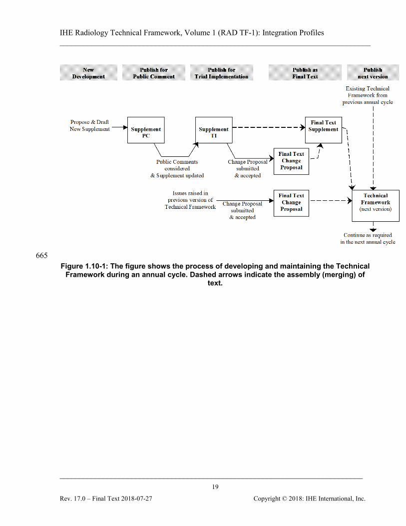
1.10 IHE Radiology Technical Framework Development and Maintenance Process
The Technical Framework is being continuously extended and maintained by the IHE Technical Committees. The Development and Maintenance Process of the Framework follows a number of principles to ensure stability of the specification both vendors and users may rely upon in 575 specifying, developing and acquiring IHE compatible products. The process is intended to address the need for extensions, clarifications and corrections while maintaining backward compatibility of framework definitions as to support implementations claiming conformance to any previously defined integration profile and its actors. To maintain stability of the IHE Technical Framework, modifications occur in a regular annual 580 cycle (Figure 1.10-1) according to one of two controlled paths:
1. New Development – Extending the Existing Technical Framework Each year, new functionality to be developed is identified by the IHE Planning Committee. The Technical Committee performs the necessary analysis and design work and generates new text for the Technical Framework. 585 Generally, new functionality is published in the form of a supplement. The scope of a supplement is to make one of the following additions to the Technical Framework:
• A new Integration Profile, usually including the introduction of new actors and transactions.
• New actors in an existing Integration Profile: These may be either actors previously 590 defined elsewhere in the Technical Framework, or new ones not yet defined. Transactions identifying the new actor’s responsibilities in this profile are identified or defined and may be designated as required or optional. To avoid causing compatibility problems for systems that have already implemented that profile, no new required transactions are added for existing actors in the profile. 595
• New options in an existing Integration Profile: These usually add optional transactions for existing actors in the profiles, or add optional features within existing transactions.
IHE Radiology Technical Framework, Volume 1 (RAD TF-1): Integration Profiles ______________________________________________________________________________
____________________________________________________________________________ 17
Rev. 17.0 – Final Text 2018-07-27 Copyright © 2018: IHE International, Inc.
• Major conceptual changes: They do not change the behavior of existing Integration Profiles but may imply changes or additions to actors or transactions in the future. 600
The publication process consists of certain phases and is clearly indicated on each document. First, the text is published for Public Comment (with a “PC” designation). During the Public Comment period (typically 30 days), the text and a comment submission facility are available on the IHE Website. Following this period, the Technical Committee will 605 review the comments. Updated text of supplements is then published for Trial Implementation (with a “TI” designation), based on the modifications resulting from the comments received. After trial implementations have been judged to have sufficiently exercised the new functionality (e.g., due to experience from the Connectathon), and the text is considered 610 sufficiently stable, the new text will be published as Final Text (with a “FT” designation). Final Text Supplements will be merged at the end of the annual development cycle with the current version of the Technical Framework resulting in a new version of the Technical Framework with an increased version number.
2. Maintenance of existing Technical Framework content 615 Despite the best efforts of the Technical Committee, a published current version of the Technical Framework or Trial Implementation documents may contain text that is incorrect, incomplete or unclear. Such issues are handled as Change Proposals and cover:
• Corrections: technical issues causing non-interoperability of implementations are fixed without introducing changes in functionality of a stable Integration Profile. 620
• Clarifications: text that can be misunderstood or is ambiguous is made easier to understand or disambiguated, without introducing any technical changes.
The publication process is the same for both Corrections and Clarifications, and addresses both changes to Trial Implementations and changes to a current version of the Technical Framework. 625 A Submitted Change Proposal results from issues raised by users, vendors or Technical Committee members, e.g., from experiences with Trial Implementation or Final Text Integration Profiles or at a Connectathon. The resulting Change Proposal document should explicitly state: 1. the parts of the Technical Framework requested to be changed, 630 2. a problem description, 3. a rationale why the change is considered necessary, 4. and a solution or approach to the problem. The Technical Committee regularly considers Change Proposals which are then either accepted or rejected. 635 A Rejected Change Proposal is published with a rationale from the Technical Committee explaining why the change is not appropriate.
IHE Radiology Technical Framework, Volume 1 (RAD TF-1): Integration Profiles ______________________________________________________________________________
____________________________________________________________________________ 18
Rev. 17.0 – Final Text 2018-07-27 Copyright © 2018: IHE International, Inc.
An Accepted Change Proposal is assigned to a member of the Technical Committee as a work item for further investigation with the goal to produce adequate clarifications or corrections. The resulting text will again be reviewed by the Technical Committee before 640 being approved. Once approved, a Final Text Change Proposal is published by the Technical Committee, and then is to be considered as effective. It will be merged into the next version of the Technical Framework at the end of the annual development cycle. Submitting a Change Proposal to a Final Text Change Proposal or a Final Text 645 Supplement is not possible.
The current version of the Technical Framework is considered the primary reference document. Final Text Supplements and Final Text Change Proposals from the current annual cycle complement this document. Past Final Text documents are retained to provide convenient summaries of differences to prior versions of the Technical Framework or Trial Implementation 650 versions of Supplements. During the annual development and maintenance cycle, it is recommended to use Technical Framework documents for implementations as follows:
• Product Implementations Products implemented based on Trial Implementation text are expected to review the 655 subsequent Final Text and update their products as necessary. Further, it is expected that vendors will monitor Final Text Change Proposals and make any corrections relevant to their product in a timely fashion.
• Connectathon Implementations Testing at the Connectathon will be based on the current version of the Technical 660 Framework for the appropriate IHE Domain, plus any relevant Supplements for Trial Implementation and Final Text Change Proposals.
IHE Radiology Technical Framework, Volume 1 (RAD TF-1): Integration Profiles ______________________________________________________________________________
____________________________________________________________________________ 19
Rev. 17.0 – Final Text 2018-07-27 Copyright © 2018: IHE International, Inc.
665 Figure 1.10-1: The figure shows the process of developing and maintaining the Technical
Framework during an annual cycle. Dashed arrows indicate the assembly (merging) of text.
IHE Radiology Technical Framework, Volume 1 (RAD TF-1): Integration Profiles ______________________________________________________________________________
____________________________________________________________________________ 20
Rev. 17.0 – Final Text 2018-07-27 Copyright © 2018: IHE International, Inc.
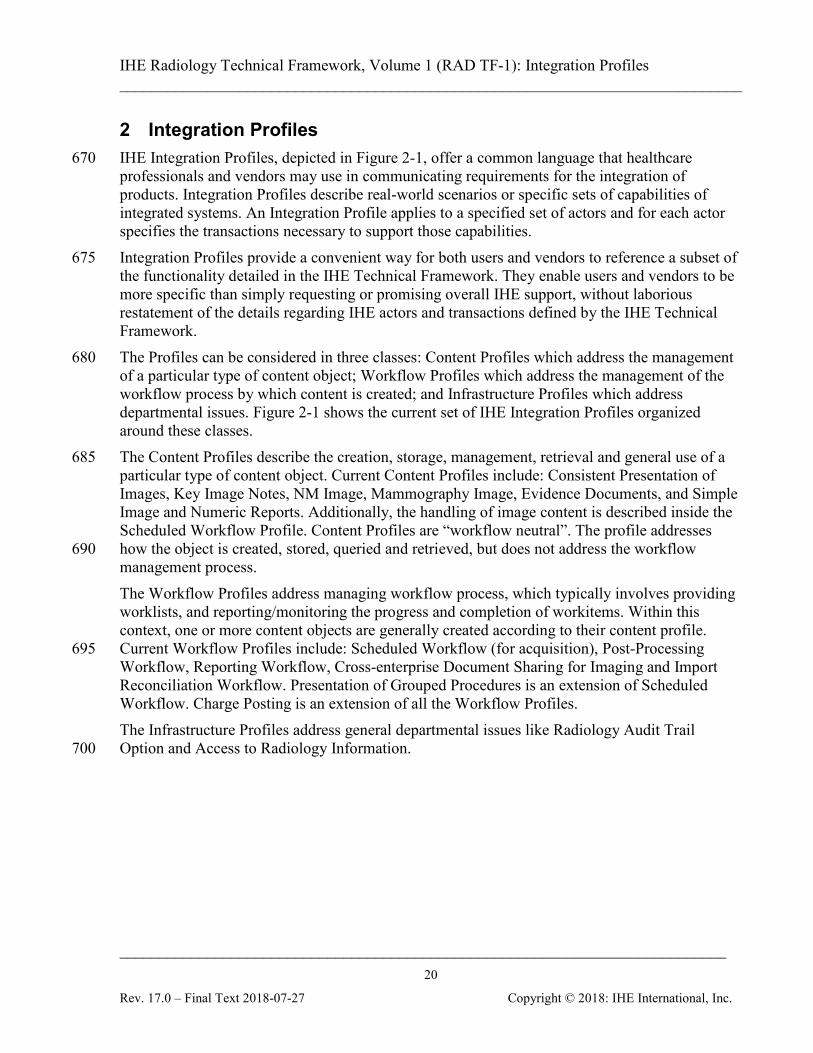
2 Integration Profiles IHE Integration Profiles, depicted in Figure 2-1, offer a common language that healthcare 670 professionals and vendors may use in communicating requirements for the integration of products. Integration Profiles describe real-world scenarios or specific sets of capabilities of integrated systems. An Integration Profile applies to a specified set of actors and for each actor specifies the transactions necessary to support those capabilities. Integration Profiles provide a convenient way for both users and vendors to reference a subset of 675 the functionality detailed in the IHE Technical Framework. They enable users and vendors to be more specific than simply requesting or promising overall IHE support, without laborious restatement of the details regarding IHE actors and transactions defined by the IHE Technical Framework. The Profiles can be considered in three classes: Content Profiles which address the management 680 of a particular type of content object; Workflow Profiles which address the management of the workflow process by which content is created; and Infrastructure Profiles which address departmental issues. Figure 2-1 shows the current set of IHE Integration Profiles organized around these classes. The Content Profiles describe the creation, storage, management, retrieval and general use of a 685 particular type of content object. Current Content Profiles include: Consistent Presentation of Images, Key Image Notes, NM Image, Mammography Image, Evidence Documents, and Simple Image and Numeric Reports. Additionally, the handling of image content is described inside the Scheduled Workflow Profile. Content Profiles are “workflow neutral”. The profile addresses how the object is created, stored, queried and retrieved, but does not address the workflow 690 management process. The Workflow Profiles address managing workflow process, which typically involves providing worklists, and reporting/monitoring the progress and completion of workitems. Within this context, one or more content objects are generally created according to their content profile. Current Workflow Profiles include: Scheduled Workflow (for acquisition), Post-Processing 695 Workflow, Reporting Workflow, Cross-enterprise Document Sharing for Imaging and Import Reconciliation Workflow. Presentation of Grouped Procedures is an extension of Scheduled Workflow. Charge Posting is an extension of all the Workflow Profiles. The Infrastructure Profiles address general departmental issues like Radiology Audit Trail Option and Access to Radiology Information. 700

IHE Radiology Technical Framework, Volume 1 (RAD TF-1): Integration Profiles ______________________________________________________________________________
____________________________________________________________________________ 21
Rev. 17.0 – Final Text 2018-07-27 Copyright © 2018: IHE International, Inc.
create, store,
manage, retrieve &
use images
manage worklists,
track status, perform &
notify acquisition
related steps,
Patient Information
Reconciliation Reconcile
worklists, status, and data objects for unknown patients and demographics
changes
Access to Radiology Information Consistent access to images and reports
Consistent Presentation
of Images Create, store,
manage, retrieve & use objects for hardcopy and
softcopy grayscale presentation states
Key Image Notes
Create, store, manage, retrieve & use objects to flag significant
images
Simple Image and Numeric
Reports Create, store,
manage, retrieve & use simple
diagnostic reports with
optional image
Scheduled Workflow Admit, order, schedule,
Presentation of Grouped
Procedures Manage individual procedure image subsets from a multi-procedure acquisition for
viewing & reporting
Charge Posting Collect and post timely
billable procedure details
Other Radiology Relevant Profiles: ITI ATNA – Radiology Audit Trail Opton, ITI RID, ITI PIX
Reporting Workflow
Manage worklists, track status, perform
& notify diagnostic
reporting steps
Evidence Documents
Create, store, manage,
retrieve & use objects to
record study evidence
Manage worklists, track status, perform & notify image processing &
CAD steps
Post-Processing Workflow
NM Image
Create, store, manage,
retrieve & use NM image
objects
Mammo Image
Create, store, manage,
retrieve & use Mammo image
objects
Import Reconciliation
Workflow Reconcile imported
data objects
Cross-Enterprise Document Sharing for Imaging Consistent sharing of images and radiology reports across
enterprise boundaries
Teaching File & Clinical
Trial Export Identify,
anonymize & store objects for teaching
files or clinical trials
Radiation Exposure
Monitoring Create, store,
manage, retrieve & use radiation dose SR object
Consistent query and retrieve mechanism for imaging information across communities
Cross-Community Access for Imaging
Portable Data for Imaging Consistent access to images and reports on CD, DVD or USB Media
Digital Breast Tomosynthesis
Create, store, manage, retrieve &
use DBT image objects
Imaging Object Change Management Consistent mechanism to communication changes in an imaging study
Figure 2-1: IHE Integration Profiles
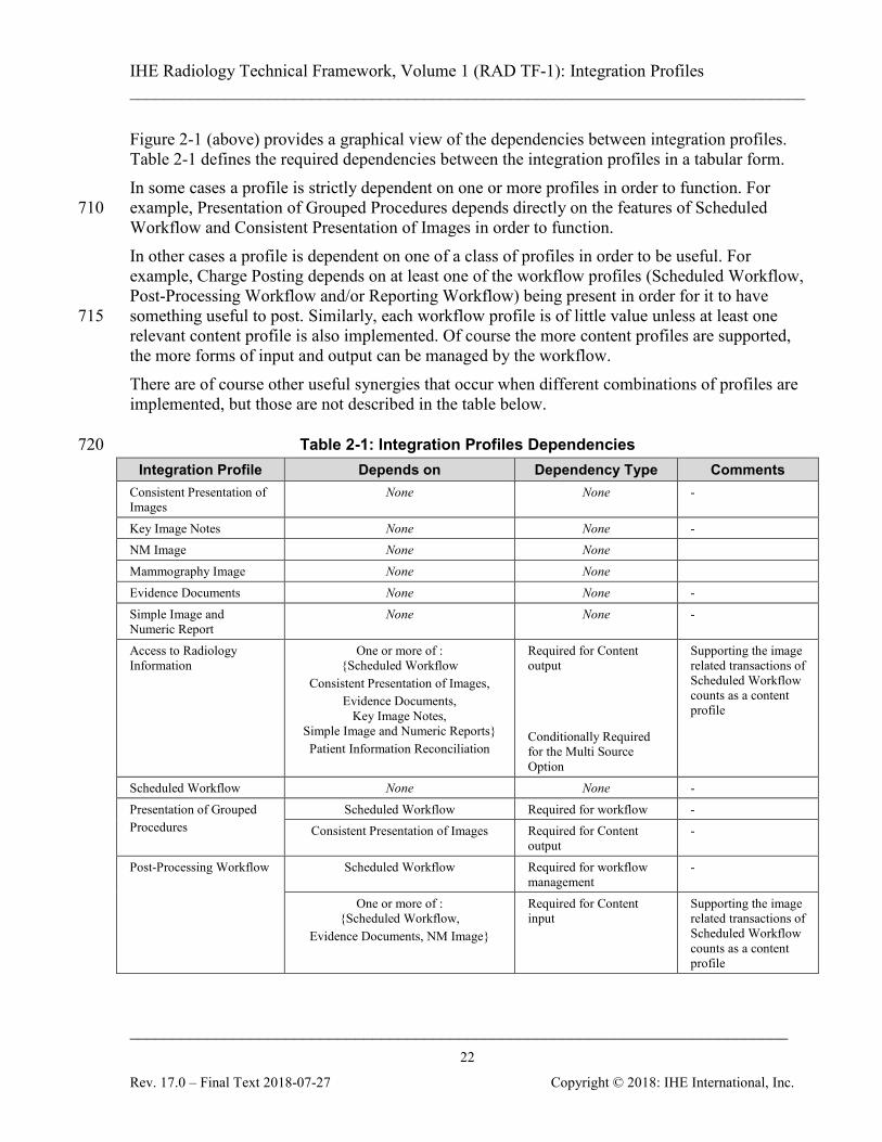
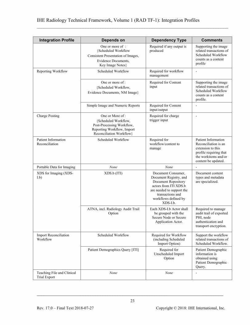
Dependencies among Integration Profiles In general, IHE Integration Profiles do not operate independently. Objects that serve as useful 705 input to one profile may have been produced as a result of implementing another profile.
IHE Radiology Technical Framework, Volume 1 (RAD TF-1): Integration Profiles ______________________________________________________________________________
____________________________________________________________________________ 22
Rev. 17.0 – Final Text 2018-07-27 Copyright © 2018: IHE International, Inc.
Figure 2-1 (above) provides a graphical view of the dependencies between integration profiles. Table 2-1 defines the required dependencies between the integration profiles in a tabular form. In some cases a profile is strictly dependent on one or more profiles in order to function. For example, Presentation of Grouped Procedures depends directly on the features of Scheduled 710 Workflow and Consistent Presentation of Images in order to function. In other cases a profile is dependent on one of a class of profiles in order to be useful. For example, Charge Posting depends on at least one of the workflow profiles (Scheduled Workflow, Post-Processing Workflow and/or Reporting Workflow) being present in order for it to have something useful to post. Similarly, each workflow profile is of little value unless at least one 715 relevant content profile is also implemented. Of course the more content profiles are supported, the more forms of input and output can be managed by the workflow. There are of course other useful synergies that occur when different combinations of profiles are implemented, but those are not described in the table below.
Table 2-1: Integration Profiles Dependencies 720 Integration Profile Depends on Dependency Type Comments
Consistent Presentation of Images
None None -
Key Image Notes None None - NM Image None None Mammography Image None None Evidence Documents None None - Simple Image and Numeric Report
None None -
Access to Radiology Information
One or more of : {Scheduled Workflow
Consistent Presentation of Images, Evidence Documents,
Key Image Notes, Simple Image and Numeric Reports} Patient Information Reconciliation
Required for Content output Conditionally Required for the Multi Source Option
Supporting the image related transactions of Scheduled Workflow counts as a content profile
Scheduled Workflow None None - Presentation of Grouped Procedures
Scheduled Workflow Required for workflow - Consistent Presentation of Images Required for Content
output -
Post-Processing Workflow Scheduled Workflow
Required for workflow management
-
One or more of : {Scheduled Workflow,
Evidence Documents, NM Image}
Required for Content input
Supporting the image related transactions of Scheduled Workflow counts as a content profile
IHE Radiology Technical Framework, Volume 1 (RAD TF-1): Integration Profiles ______________________________________________________________________________
____________________________________________________________________________ 23
Rev. 17.0 – Final Text 2018-07-27 Copyright © 2018: IHE International, Inc.
Integration Profile Depends on Dependency Type Comments One or more of :
{Scheduled Workflow Consistent Presentation of Images,
Evidence Documents, Key Image Notes}
Required if any output is produced
Supporting the image related transactions of Scheduled Workflow counts as a content profile
Reporting Workflow Scheduled Workflow
Required for workflow management
-
One or more of : {Scheduled Workflow,
Evidence Documents, NM Image}
Required for Content input
Supporting the image related transactions of Scheduled Workflow counts as a content profile.
Simple Image and Numeric Reports Required for Content input/output
-
Charge Posting One or More of : {Scheduled Workflow,
Post-Processing Workflow, Reporting Workflow, Import Reconciliation Workflow}
Required for charge trigger input
-
Patient Information Reconciliation
Scheduled Workflow Required for workflow/content to manage
Patient Information Reconciliation is an extension to this profile requiring that the workitems and/or content be updated.
Portable Data for Imaging None None - XDS for Imaging (XDS-I.b)
XDS.b (ITI) Document Consumer, Document Registry, and Document Repository actors from ITI XDS.b
are needed to support the transactions and
workflows defined by XDS-I.b.
Document content types and metadata are specialized.
ATNA, incl. Radiology Audit Trail Option
Each XDS-I.b Actor shall be grouped with the
Secure Node or Secure Application Actor.
Required to manage audit trail of exported PHI, node authentication and transport encryption.
Import Reconciliation Workflow
Scheduled Workflow Required for Workflow (including Scheduled
Import Option)
Support the workflow related transactions of Scheduled Workflow.
Patient Demographics Query [ITI] Required for Unscheduled Import
Option
Patient Demographic information is obtained using Patient Demographic Query.
Teaching File and Clinical Trial Export
None None -
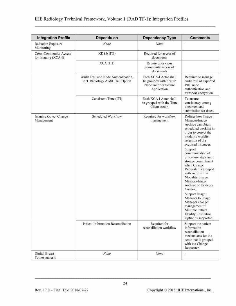
IHE Radiology Technical Framework, Volume 1 (RAD TF-1): Integration Profiles ______________________________________________________________________________
____________________________________________________________________________ 24
Rev. 17.0 – Final Text 2018-07-27 Copyright © 2018: IHE International, Inc.
Integration Profile Depends on Dependency Type Comments Radiation Exposure Monitoring
None None -
Cross-Community Access for Imaging (XCA-I)
XDS.b (ITI) Required for access of documents
XCA (ITI) Required for cross community access of
documents
Audit Trail and Node Authentication, incl. Radiology Audit Trail Option
Each XCA-I Actor shall be grouped with Secure Node Actor or Secure
Application
Required to manage audit trail of exported PHI, node authentication and transport encryption.
Consistent Time (ITI) Each XCA-I Actor shall be grouped with the Time
Client Actor.
To ensure consistency among document and submission set dates.
Imaging Object Change Management
Scheduled Workflow
Required for workflow management
Defines how Image Manager/Image Archive can obtain scheduled worklist in order to correct the modality worklist selection of the acquired instances. Support communication of procedure steps and storage commitment when Change Requester is grouped with Acquisition Modality, Image Manager/Image Archive or Evidence Creator. Support Image Manager to Image Manager change management if Multiple Patient Identity Resolution Option is supported.
Patient Information Reconciliation Required for reconciliation workflow
Support the patient information reconciliation mechanisms for the actor that is grouped with the Change Requester.
Digital Breast Tomosynthesis
None None -
IHE Radiology Technical Framework, Volume 1 (RAD TF-1): Integration Profiles ______________________________________________________________________________
____________________________________________________________________________ 25
Rev. 17.0 – Final Text 2018-07-27 Copyright © 2018: IHE International, Inc.
Vendor products support an Integration Profile by implementing the appropriate actor-transactions as outlined in the Integration Profile in Sections 3-40. A product may implement more than one actor and more than one Integration Profile. An actor must implement all required transactions in the pre-requisite profiles in addition to 725 those in the desired profile. In some cases, the pre-requisite is that the actor selects any one of a given set of profiles to satisfy the pre-requisite. For example, Post-processing depends on any one of the content profiles being supported. Actors (see Section 2.3) are information systems or components of information systems that produce, manage, or act on information associated with operational activities in the enterprise. 730 Transactions (see Section 2.4) are interactions between actors that transfer the required information through standards-based messages.
2.1 Integration Profiles Overview In this document, each IHE Integration Profile is defined by:
• The IHE actors involved 735
• The specific set of IHE Transactions required for each IHE actor. These requirements are presented in the form of a table of transactions required for each actor supporting the Integration Profile. Actors supporting multiple Integration Profiles are required to support all the required transactions of each Integration Profile supported. When an Integration Profile depends upon another Integration Profile, all transactions required for the dependent 740 Integration Profile have been included in the table. As mentioned earlier, there is a class of Profiles that deal primarily with data content. Most types of content belong to the family of Evidence Objects. Currently this means Images, Presentation States, Key Image Notes and Evidence Documents. Evidence Objects are generated as a result of performing procedure steps on systems in the radiology department. These objects are used by 745 the Radiologist in the process of creating a Radiological Diagnostic Report and are managed inside the Radiology Department. Evidence Documents represent the uninterpreted information that is primarily managed and used inside Radiology, although distribution outside Radiology is not precluded. In contrast, the diagnostic reports described in the Simple Image and Numeric Reports Profile represent the interpreted information which is the primary output of the 750 Radiology department and are available for wide distribution. Note that IHE Integration Profiles are not statements of conformance to standards, and IHE is not a certifying body. Users should continue to request that vendors provide statements of their conformance to relevant standards, such as DICOM and HL7. Standards conformance is a prerequisite for vendors adopting IHE Integration Profiles. 755 Also note that there are critical needs for any successful integration project that IHE cannot address. Successfully integrating systems still requires a project plan that minimizes disruptions and describes fail-safe strategies, specific and mutually understood performance expectations,
IHE Radiology Technical Framework, Volume 1 (RAD TF-1): Integration Profiles ______________________________________________________________________________
____________________________________________________________________________ 26
Rev. 17.0 – Final Text 2018-07-27 Copyright © 2018: IHE International, Inc.
well-defined user interface requirements, clearly identified systems limitations, detailed cost objectives, plans for maintenance and support, etc. 760
2.1.1 Scheduled Workflow (SWF) The Scheduled Workflow Integration Profile establishes the continuity and integrity of basic departmental imaging data acquired in an environment where examinations are generally being ordered. It specifies a number of transactions that maintain the consistency of patient and ordering information as well as defining the scheduling and imaging acquisition procedure steps. 765 This profile also makes it possible to determine whether images and other evidence objects associated with a particular performed procedure step have been stored (archived) and are available to enable subsequent workflow steps, such as reporting. It may also provide central coordination of the completion of processing and reporting steps as well as notification of appointments to the Order Placer. 770
2.1.2 Patient Information Reconciliation (PIR) The Patient Information Reconciliation Integration Profile extends the Scheduled Workflow Integration Profile by offering the means to match images, diagnostic reports, and other evidence objects acquired for a misidentified or unidentified patient (for example, during a trauma case) with the patient’s record. In the example of the trauma case, this integration profile 775 allows subsequent reconciliation of the patient record with images that are acquired (either without a prior registration or under a generic registration) before the patient’s identity could be determined. Thus images, diagnostic reports and other evidence objects can be acquired and interpreted immediately and later, when the patient’s official registration and order information is entered into the ADT, Order Placer and Order Filler Systems, this information is matched with 780 the acquired image set, greatly simplifying these exception-handling situations.
2.1.3 Consistent Presentation of Images (CPI) The Consistent Presentation of Images Integration Profile specifies a number of transactions that maintain the consistency of presentation for grayscale images and their presentation state information (including user annotations, shutters, flip/rotate, display area, and zoom). It also 785 defines a standard contrast curve, the Grayscale Standard Display Function, against which different types of display and hardcopy output devices can be calibrated. It thus supports hardcopy, softcopy and mixed environments.
2.1.4 Presentation of Grouped Procedures (PGP) The Presentation of Grouped Procedures Integration Profile (PGP) addresses what is sometimes 790 referred to as the linked studies problem: viewing image subsets resulting from a single acquisition with each image subset related to a different requested procedure (e.g., CT chest, abdomen and pelvis). It provides a mechanism for facilitating workflow when viewing images and reporting on individual requested procedures that an operator has grouped (often for the sake of acquisition efficiency and patient comfort). A single acquired image set is produced, but the 795 combined use of the scheduled workflow transactions and the consistent presentation of images
IHE Radiology Technical Framework, Volume 1 (RAD TF-1): Integration Profiles ______________________________________________________________________________
____________________________________________________________________________ 27
Rev. 17.0 – Final Text 2018-07-27 Copyright © 2018: IHE International, Inc.
allow separate viewing and interpretation of the image subsets related to each of the requested procedures.
2.1.5 Access to Radiology Information (ARI) The Access to Radiology Information Integration Profile specifies a number of query 800 transactions providing access to radiology information, including images and related reports, in a DICOM format as they were acquired or created. Such access is useful both to the radiology department and to other departments such as pathology, surgery and oncology.
2.1.6 Key Image Note (KIN) The Key Image Note Integration Profile specifies transactions that allow a user to mark one or 805 more images in a study as significant by attaching to them a note managed together with the study. This note includes a title stating the purpose of marking the images and a user comment field. Physicians may attach Key Image Notes to images for a variety of purposes: referring physician access, teaching files selection, consultation with other departments, and image quality issues, etc. 810
2.1.7 Simple Image and Numeric Report (SINR) The Simple Image and Numeric Report Integration Profile facilitates the growing use of digital dictation, voice recognition, and specialized reporting packages, by separating the functions of reporting into discrete actors for creation, management, storage and viewing. Separating these functions while defining transactions to exchange the reports between them enables a vendor to 815 include one or more of these functions in an actual system.
2.1.8 Basic Security (SEC) - DEPRECATED This profile has been superseded by the ITI Audit Trail and Node Authentication (ATNA) Integration Profile and the Radiology Audit Trail Option on ATNA. See Sections 2.2.1 and 10 for details on backward compatibility of this option and the Basic Security Profile. 820
2.1.9 Charge Posting (CHG) The Charge Posting Integration Profile specifies the exchange of information from the Department System Scheduler/Order Filler Actor to the Charge Processor Actor regarding charges associated with particular procedures, as well as communication between the ADT/Patient Registration and Charge Processor Actors about patient demographics, accounts, 825 insurance, and guarantors. The Charge Posted Transaction contains all of the required procedure data to generate a claim. Currently, these interfaces contain fixed field formatted or HL7-style data. The goal of including this transaction in the Radiology Technical Framework is to standardize the Charge Posted Transaction to a Charge Processor, thus reducing system interface installation time between clinical systems and Charge Processors. Additionally, the Charge 830 Posted Transaction reduces the need of the billing system to have knowledge of the radiology internals. The result is that the Charge Processor will receive more complete, timely and accurate data.
IHE Radiology Technical Framework, Volume 1 (RAD TF-1): Integration Profiles ______________________________________________________________________________
____________________________________________________________________________ 28
Rev. 17.0 – Final Text 2018-07-27 Copyright © 2018: IHE International, Inc.
2.1.10 Post-Processing Workflow (PWF) The Post-Processing Workflow Integration Profile addresses the need to schedule, distribute and 835 track the status of typical post-processing workflow steps, such as Computer-Aided Detection or Image Processing. Worklists for each of these tasks are generated and can be queried, workitems can be selected and the resulting status returned from the system performing the work to the system managing the work. IMPORTANT NOTE: As of June 2012, IHE introduces a new Trial Implementation Profile: Post-Acquisition Workflow (PAWF). The use cases addressed 840 are largely the same as PWF, but the underlying mechanisms are improved. The PWF Profile documented in this section has been deprecated by the Radiology Domain and is now replaced by PAWF. When the PAWF Profile becomes Final Text, the contents of Section 10 will be removed. In the interim, new implementations should be based on PAWF, found at http://ihe.net/Technical_Frameworks/#radiology. 845
2.1.11 Reporting Workflow (RWF) The Reporting Workflow Profile addresses the need to schedule, distribute and track the status of the reporting workflow tasks such as interpretation, transcription and verification. Worklists for each of these tasks are generated and can be queried; workitems can be selected and the resulting status returned from the system performing the work to the system managing the work. 850
2.1.12 Evidence Documents (ED) The Evidence Documents Profile defines interoperable ways for observations, measurements, results and other procedure details recorded in the course of carrying out a procedure step to be output by devices, such as acquisition systems and other workstations; to be stored and managed by archival systems; and to be retrieved and presented by display and reporting systems. This 855 allows detailed non-image information, such as measurements, CAD results, procedure logs, etc. to be made available as input to the process of generating a diagnostic report. The Evidence Documents may be used either as additional evidence for the reporting physician or in some cases for selected items in the Evidence Document to be included in the diagnostic report.
2.1.13 Portable Data for Imaging (PDI) 860 The Portable Data for Imaging Integration Profile specifies actors and transactions that allow users to distribute imaging related information on interchange media. The intent of this profile is to provide reliable interchange of evidence objects and diagnostic reports for import, display or print by a receiving actor. The CD format with uncompressed content was chosen as the baseline. Options for the support of DVD media and USB, JPEG and JPEG 2000 lossless and 865 lossy compression on CD, DVD and USB media are also defined.
2.1.14 NM Image (NMI) The NM Image Integration Profile specifies how Acquisition Modalities and workstations should store NM Images and how Image Displays should retrieve and make use of them. It defines the basic display capabilities Image Displays are expected to provide, and also how result screens, 870
IHE Radiology Technical Framework, Volume 1 (RAD TF-1): Integration Profiles ______________________________________________________________________________
____________________________________________________________________________ 29
Rev. 17.0 – Final Text 2018-07-27 Copyright © 2018: IHE International, Inc.
both static and dynamic, such as those created by NM Cardiac Processing Packages, should be stored using DICOM objects that can be displayed on general purpose Image Display systems.
2.1.15 Teaching File and Clinical Trial Export (TCE) The Teaching File and Clinical Trial Export Profile addresses the need to select DICOM instances, series or studies (which may contain images, key image notes, reports, evidence 875 documents and presentation states) that need to be exported for teaching files or clinical trials. It defines an actor for making the Export Selection, which would typically be grouped with an Image Display or Acquisition Modality, and an actor for processing the selection, which is required to support a configurable means of de-identifying the exported instances. Additional options are provided for de-identification of pixel data, remapping of identifiers to 880 pseudonymous values, export of additional teaching file information, and delaying export for a variety of reasons.
2.1.16 Cross-Enterprise Document Sharing for Imaging (XDS-I.b) The Cross-Enterprise Document Sharing for Imaging (XDS-I.b) Integration Profile specifies actors and transactions that allow users to share imaging information across enterprises. This 885 profile depends on the IHE IT Infrastructure Cross-Enterprise Document Sharing (XDS.b) Profile. Cross-Enterprise Document Sharing for Imaging (XDS-I.b) defines the information to be shared such as sets of DICOM instances (including images, evidence documents, and presentation states), diagnostic imaging reports provided in a ready-for-display format. Since the XDS-I.b Profile depends on and extends the IT Infrastructure XDS.b Profile including 890 the use of terms defined in XDS (e.g., XDS Affinity Domain, submission set, etc.) the reader of XDS-I.b is expected to have read and understood the XDS Profile.
2.1.17 Mammography Image (MAMMO) The Mammography Image Profile specifies how DICOM Mammography images and evidence objects are created, exchanged and used. It describes how Acquisition Modalities transfer Full 895 Field Digital Mammography (FFDM) Images, how CAD systems act as Evidence Creators, and how Image Displays should retrieve and make use of images and CAD results. It defines the basic display capabilities Image Displays are expected to provide, and which attributes should be used to implement those capabilities.
2.1.18 Image Fusion (FUS) 900 This section intentionally, temporarily left blank.
2.1.19 Import Reconciliation Workflow (IRWF) The Import Reconciliation Workflow Integration Profile (IRWF) specifies how data Importers obtain local demographics, coerce patient and procedure attribute values in the imported data and report progress/status of the importation process. The Profile complements the Scheduled 905 Workflow Profile by using the existing workflow mechanisms for notification and storage of
IHE Radiology Technical Framework, Volume 1 (RAD TF-1): Integration Profiles ______________________________________________________________________________
____________________________________________________________________________ 30
Rev. 17.0 – Final Text 2018-07-27 Copyright © 2018: IHE International, Inc.
imported Evidence Objects. IMPORTANT NOTE: As of June 2012, IHE introduces an updated Import Reconciliation Profile (IRWF.b) for Trial Implementation. In addition to the original use cases, several new use cases are addressed, and the underlying mechanisms are improved. The IRWF Profile documented in this section has been deprecated by the Radiology 910 Domain and is now replaced by the IRWF.b. When that supplement becomes Final Text, the contents of Section 21 will be removed. In the interim, new implementations should be based on IRWF.b, found at http://www.ihe.net/Technical_Frameworks/#radiology.
2.1.20 Radiation Exposure Monitoring (REM) The Radiation Exposure Monitoring Integration Profile specifies communications between 915 systems generating reports of irradiation events (generally acquisition modalities and workstations) and systems which receive, store, or process those reports (generally local dose information management systems and/or national/regional dose registries). It defines how DICOM SR objects for CT and projection X-ray dose objects are created, stored, queried, retrieved, de-identified, and may be processed and displayed. 920
2.1.21 Mammography Acquisition Workflow (MAWF) This section intentionally, temporarily left blank.
2.1.22 MR Diffusion Imaging (DIFF) This section intentionally, temporarily left blank.
2.1.23 CT/MR Perfusion Imaging with Contrast (PERF) 925 This section intentionally, temporarily left blank.
2.1.24 Basic Image Review (BIR) This section intentionally, temporarily left blank.
2.1.25 Chest X-Ray CAD Display (CXCAD) This section intentionally, temporarily left blank. 930
2.1.26 Imaging Object Change Management (IOCM) The Imaging Object Change Management Integration Profile (IOCM) specifies how one actor communicates local changes applied on existing imaging objects to other actors that manage copies of the modified imaging objects in their own local systems. The supported changes include (1) object rejection due to quality or patient safety reasons, (2) correction of incorrect 935 modality worklist entry selection, and (3) expiration of objects due to data retention requirements. It defines how changes are captured and how to communicate these changes.
IHE Radiology Technical Framework, Volume 1 (RAD TF-1): Integration Profiles ______________________________________________________________________________
____________________________________________________________________________ 31
Rev. 17.0 – Final Text 2018-07-27 Copyright © 2018: IHE International, Inc.
2.1.27 Cross-Community Access for Imaging (XCA-I) The Cross-Community Access for Imaging (XCA-I) Integration Profile specifies actors and transactions to query and retrieve patient-relevant medical imaging data being held by other 940 communities. Within a community, a group of facilities/enterprises shares clinical information via an established mechanism such as XDS-I (in which case the community can be referred to as an XDS Affinity Domain). This profile addresses sharing between such communities. The XCA-I Profile extends the IT Infrastructure XCA Profile. XCA provides access to 945 Diagnostic reports and Imaging Manifests. XCA-I provides access to the imaging objects referenced in the Manifests. The reader of XCA-I is expected to have read and understood the XCA Profile, including the meaning of terms such as Community, homeCommunityId, etc.
2.1.28 Post Acquisition Workflow (PAWF) This section intentionally, temporarily left blank. 950
2.1.29 Cross-Enterprise Reliable Document Interchange – Imaging (XDR-I) This section intentionally, temporarily left blank.
2.1.30 Stereotactic Mammography Image (SMI) This section intentionally, temporarily left blank.
2.1.31 Management of Radiology Report Templates (MRRT) 955 This section intentionally, temporarily left blank.
2.1.32 Scheduled Workflow.b (SWF.b) This section intentionally, temporarily left blank.
2.1.33 Invoke Image Display (IID) This section intentionally, temporarily left blank. 960
2.1.34 Intentionally Left Blank This section is intentionally left blank.
2.1.35 Digital Breast Tomosynthesis (DBT) The Digital Breast Tomosynthesis (DBT) Profile specifies the creation, exchange and use of DBT images. It defines basic display capabilities that Image Displays are expected to provide, 965 especially simultaneous review of DBT and conventional 2D mammography images (FFDM). The Digital Breast Tomosynthesis Profile is designed to provide faithful storage and retrieval of DBT images. Furthermore, sufficient display functionality to allow adequate review of current
IHE Radiology Technical Framework, Volume 1 (RAD TF-1): Integration Profiles ______________________________________________________________________________
____________________________________________________________________________ 32
Rev. 17.0 – Final Text 2018-07-27 Copyright © 2018: IHE International, Inc.
and prior studies consisting of DBT and/or conventional 2D mammography images is defined. The support for CAD is out of the scope for this profile. 970
2.1.36 Web-based Image Capture (WIC) This section intentionally, temporarily left blank.
2.1.37 Clinical Decision Support – Order Accountable Tracking (CDS-OAT) This section intentionally, temporarily left blank.
2.1.38 Radiation Exposure Monitoring – Nuclear Medicine (REM-NM) 975 This section intentionally, temporarily left blank.
2.1.39 Cross-Enterprise Remote Read Workflow Definition (XRR-WD) This section intentionally, temporarily left blank.
2.1.40 Web-based Image Access (WIA) This section intentionally, temporarily left blank. 980
2.1.41 Standardized Operational Log Events (SOLE) This section intentionally, temporarily left blank.
2.1.42 Management of Acquisition Protocols (MAP) This section intentionally, temporarily left blank.
2.1.43 Results Distribution (RD) 985 This section intentionally, temporarily left blank.
2.1.44 Intentionally Left Blank This section is intentionally left blank.
2.1.45 Encounter-based Imaging Workflow (EBIW) This section intentionally, temporarily left blank. 990
2.2 Options to other Domains’ Profiles
2.2.1 ITI-Audit Trail and Node Authentication The Radiology Audit Trail Option is an option on the ITI Audit Trail and Node Authentication (ATNA) Profile. The ITI-ATNA Profile provides security and privacy mechanisms like a common audit trail and authentication for distributed applications. Refer to the ATNA Profile 995 (ITI TF-1: 9) for the full definition of this profile.
IHE Radiology Technical Framework, Volume 1 (RAD TF-1): Integration Profiles ______________________________________________________________________________
____________________________________________________________________________ 33
Rev. 17.0 – Final Text 2018-07-27 Copyright © 2018: IHE International, Inc.
The Radiology Audit Trail Option deals largely with the details of the Record Audit Event transaction in the IHE ITI Technical Framework. It defines audit events on IHE Radiology transactions for a Secure Node. This option does not extend the Authenticate Node transaction in the ATNA Profile. 1000
2.3 Actor Descriptions Actors are information systems or components of information systems that produce, manage, or act on information associated with operational activities in the enterprise. The following are the actors defined by IHE and referenced throughout the rest of this document. It is acknowledged that some of the terms used as modifiers for the actor names are not used 1005 consistently (e.g., Evidence Creator, Image Display). At this point, the benefit in doing extensive renaming to gain consistency is outweighed by the risk of introducing significant confusion that would result from renaming many of the existing actors. Therefore the actor names will remain as defined below. Acquisition Modality – A system that acquires and creates medical images while a patient is 1010 present, e.g., a Computed Tomography scanner or Nuclear Medicine camera. A modality may also create other evidence objects such as Grayscale Softcopy Presentation States for the consistent viewing of images or Evidence Documents containing measurements. A modality may also create and store Dose SRs. ADT Patient Registration – A system responsible for adding and/or updating patient 1015 demographic and encounter information. In particular, it registers a new patient with the Order Placer and Department System. Charge Processor – Receives the posted charges and serves as a component of the financial system. Further definition of this actor is beyond current IHE scope. Change Requester – A system that communicates changes to an Image Manager / Archive, 1020 indicating that certain imaging instances should be deleted. In addition, it may also send new versions of these imaging instances containing corrected information. Department System Scheduler/Order Filler – A department-based information system (for instance, Radiology or Laboratory) that provides functions related to the management of orders received from external systems or through the department system’s user interface. Upon a 1025 defined workflow action, makes procedures available for charge posting. The action/event that actually causes charges to post is defined by the actor. Display – Primary description for this actor can be found in ITI TF-1: Appendix A. The required capabilities for its use within the Radiology Technical Framework add the ability to view "web-viewable" diagnostic and therapeutic imaging information on interchange media. 1030 Document Consumer – The Document Consumer Actor queries a Document Registry Actor for documents meeting certain criteria, and retrieves selected documents from one or more Document Repository Actors. Document Registry – The Document Registry Actor maintains meta-data about each registered document in a document entry. This includes a link to the Document Repository where the actual 1035 document is stored. The Document Registry responds to queries from Document Consumer
IHE Radiology Technical Framework, Volume 1 (RAD TF-1): Integration Profiles ______________________________________________________________________________
____________________________________________________________________________ 34
Rev. 17.0 – Final Text 2018-07-27 Copyright © 2018: IHE International, Inc.
Actors about documents meeting specific criteria. It also enforces some healthcare specific technical policies at the time of document registration. Document Repository – The Document Repository Actor persistently stores documents. It assigns and maintains a unique identifier for each document, to allow Document Consumers to 1040 retrieve them. Dose Information Consumer – Responsible for supplemental handling of irradiation events, generally on an individual basis (e.g., display, analysis, or further processing). Dose Information Reporter – Responsible for the aggregation, analysis, reporting and business logic related to irradiation events, which may include meeting facility obligations to de-identify 1045 and submit data to various dose registries. Dose Registry – Collates information about irradiation events from a number of facilities, generally to perform analysis. Enterprise Report Repository – A system that receives Structured Report Export Transactions from the Report Manager and stores them. 1050 Evidence Creator – A system that creates additional evidence objects such as images, presentation states, Key Image Notes, and/or Evidence Documents and transmits them to an Image Archive. It also makes requests for storage commitment to the Image Manager for the data previously transmitted. It may also retrieve worklist entries for post-processing steps from the Post-Processing Manager and provide notification of completion of the step, allowing the 1055 enterprise to track the status of post-processing work. Export Manager – A system that can de-identify and pseudonymize the attributes, and optionally the pixel data, of a selected list of instances, before exporting them. Export Selector – A system that allows a user to select one or more instances, series or studies for export, for a specific purpose, with a specific disposition, optionally with the inclusion of 1060 additional information. External Report Repository Access – A system that performs retrieval of clinical reports containing information generated outside the imaging department and presented as DICOM Structured Reporting Objects. Image Archive – A system that provides long term storage of evidence objects such as images, 1065 presentation states, Key Image Notes, Evidence Documents and Dose SR. Image Display – A part of a system that can access imaging evidence objects (images, Presentation States, Key Image Notes, Evidence Documents) through network query/retrieve or reading interchange media and allow the user to view these objects. Image Manager – A system that provides functions related to safe storage and management of 1070 evidence objects. It supplies availability information for those objects to the Department System Scheduler. It also accepts/commits dose data and supports query/retrieve. Imaging Document Consumer – The Imaging Document Consumer Actor parses an imaging manifest document that is retrieved by the Document Consumer Actor from the Document Repository Actor, and retrieves DICOM SOP Instances referenced within that manifest from the 1075 Imaging Document Source Actor.
IHE Radiology Technical Framework, Volume 1 (RAD TF-1): Integration Profiles ______________________________________________________________________________
____________________________________________________________________________ 35
Rev. 17.0 – Final Text 2018-07-27 Copyright © 2018: IHE International, Inc.
Imaging Document Source – The Imaging Document Source Actor is the producer and publisher of imaging documents. It is responsible for providing imaging documents and meta-data to the Document Repository Actor, which subsequently registers the imaging documents with the Document Registry Actor. It also supports the retrieval services for DICOM SOP 1080 Instances referenced in a published imaging manifest document. Importer – A system that imports evidence objects such as images, presentation states, Key Image Notes or Evidence Documents from hardcopy or digital media. Master Patient Index (MPI) – A system that maintains unique enterprise-wide identifiers for patients. Note that this is not supported in the current scope of the IHE Technical Framework 1085 Order Placer – A hospital or enterprise-wide system that generates orders for various departments and distributes those orders to the correct department. Patient Demographics Supplier – A repository of patient information that can be searched on demographic related fields. This actor is defined in the ITI Technical Framework. Performed Procedure Step Manager – A system that re-distributes the Modality Performed 1090 Procedure Step information from the Acquisition Modality or Evidence Creator to the Department System Scheduler/Order Filler, Image Manager and Report Manager. Portable Media Creator – This actor assembles the content of the media and writes it to the physical medium. Portable Media Importer – This actor reads the DICOM information contained on the media, 1095 and allows the user to select DICOM instances, reconcile key patient and study attributes, and store these instances. The actor grouped with the Media Importer can then process the instances. Post-Processing Manager – A system that provides functions related to post-processing worklist management. This involves the ability to schedule post-processing worklist items (scheduled procedure steps), provide worklist items to post-processing worklist clients, and 1100 update the status of scheduled and performed procedure steps as received from post-processing worklist clients. Print Composer – A system that generates DICOM print requests to the Print Server. Print requests include presentation state information in the form of Presentation Look-Up Tables (Presentation LUTs). It may also read the DICOM information contained on interchange media. 1105 Print Server – A system that accepts and processes DICOM print requests as a DICOM Print SCP and performs image rendering on hardcopy media. The system must support pixel rendering according to the DICOM Grayscale Standard Display Function. Receiver – A system that can receive exported instances over the network, whose behavior is otherwise unspecified unless grouped with other actors. 1110 Report Creator – A system that generates and transmits draft (and optionally, final) diagnostic reports, presenting them as DICOM Structured Reporting Objects. It may also retrieve worklist entries for reporting steps from the Report Manager and provide notification of completion of the step, allowing the enterprise to track the status of an awaited report. Report Manager – A system that provides management and short-term storage of DICOM 1115 Structured Report objects during the reporting process then distributes text or structured reports to report repositories. It also manages the worklists and status of reporting.
IHE Radiology Technical Framework, Volume 1 (RAD TF-1): Integration Profiles ______________________________________________________________________________
____________________________________________________________________________ 36
Rev. 17.0 – Final Text 2018-07-27 Copyright © 2018: IHE International, Inc.
Report Reader – A part of a system that can access reports through network query/retrieve or reading interchange media and allow the user to view reports presented as DICOM Structured Reporting Objects. 1120 Report Repository – A system that provides long-term storage of diagnostic reports and their retrieval as DICOM Structured Reporting Objects. Initiating Imaging Gateway – The Initiating Imaging Gateway Actor proxies Imaging Document Set Retrieve requests from an Image Document Consumer to a Responding Imaging Gateway with a Cross Gateway Retrieve Imaging Document Set transaction. 1125 Responding Imaging Gateway – The responding Imaging Gateway proxies Cross Gateway Retrieve Imaging Document Set requests from an Initiating Imaging Gateway to an Imaging Document Source with an Image Document Set Retrieve request.
2.4 Transaction Descriptions Transactions are interactions between actors that transfer the required information through 1130 standards-based messages. The following are the transactions defined by IHE and referenced throughout the rest of this document. 1. Patient Registration – The ADT system registers and/or admits a patient and forwards the
information to other information systems. 2. Placer Order Management – The Order Placer informs the Order Filler of the initiation or 1135
cancellation of an order. The Placer/Filler Order Management transaction will sometimes be referred to as “-New” when a new order is being initiated, or as “-Cancel” when an existing order is canceled.
3. Filler Order Management – The Order Filler informs the Order Placer of the initiation, cancellation, or change in the status of an order. The Placer/Filler Order Management 1140 transaction will sometimes be referred to as “-New” when a new order is being initiated, or as “-Cancel” when an existing order is canceled.
4. Procedure Scheduled – Schedule information is sent from the Department System Scheduler/Order Filler to the Image Manager and to the Report Manager.
5. Query Modality Worklist – In response to a query (with optional filtering) a list of 1145 Scheduled Procedure Steps with selected demographic and order information is returned.
6. Modality Procedure Step In Progress – An Acquisition Modality notifies the Performed Procedure Step Manager of the start of a new Procedure Step and the PPS Manager informs the Department System, Image Manager and the Report Manager.
7. Modality Procedure Step Completed – An Acquisition Modality notifies the Performed 1150 Procedure Step Manager of the completion of a Procedure Step and the PPS Manager informs the Department System, Image Manager and the Report Manager.
8. Modality Images Stored – An Acquisition Modality sends acquired or generated images to the Image Archive.
9. Modality Presentation State Stored – An Acquisition Modality requests that the Image 1155 Archive store a Grayscale Softcopy Presentation State (GSPS) for the acquired or generated images.
IHE Radiology Technical Framework, Volume 1 (RAD TF-1): Integration Profiles ______________________________________________________________________________
____________________________________________________________________________ 37
Rev. 17.0 – Final Text 2018-07-27 Copyright © 2018: IHE International, Inc.
10. Storage Commitment – Request and receive from an actor which has stored DICOM objects (such as images or Evidence Documents) confirmation of receipt and ownership for the specified objects, generally to allow the requesting actor to safely delete those objects. 1160
11. Images Availability Query – The Department System Scheduler/Order Filler and Report Manager asks the Image Manager if a particular image or image series is available.
12. Patient Update – The ADT Patient Registration System informs the Order Placer and the Department System Scheduler/Order Filler of new information for a particular patient. The Department System Scheduler may then further inform the Image Manager and Report 1165 Manager.
13. Procedure Update – The Department System Scheduler/Order Filler sends the Image Manager and Report Manager updated order or procedure information.
14. Query Images – An Image Display queries the Image Archive for a list of entries representing images by patient, study, series, or instance. 1170
15. Query Presentation States – An Image Display queries the Image Archive for a list of entries representing image Grayscale Softcopy Presentation States (GSPS) by patient, study, series, or instance.
16. Retrieve Images – An Image Display or an Imaging Document Consumer requests and retrieves a particular image or set of images from the Image Archive or an Imaging 1175 Document Source, respectively.
17. Retrieve Presentation States – An Image Display or an Imaging Document Consumer requests and retrieves the Grayscale Softcopy Presentation State (GSPS) information for a particular image or image set.
18. Creator Images Stored – An Evidence Creator sends new images to the Image Archive. 1180 19. Creator Presentation State Stored – An Evidence Creator requests that the Image Archive
store the created Grayscale Softcopy Presentation State objects. 20. Creator Procedure Step In Progress – An Evidence Creator notifies the Performed
Procedure Step Manager of the start of a new Procedure Step and the PPS Manager informs the Department System and Image Manager. 1185
21. Creator Procedure Step Completed – An Evidence Creator notifies the Performed Procedure Step Manager of the completion of a Procedure Step and the PPS Manager informs the Department System and Image Manager.
22. Intentionally unassigned 23. Print Request with Presentation LUT – A Print Composer sends a print request to the Print 1190
Server specifying Presentation LUT information. 24. Report Submission – A Report Creator sends a draft or final diagnostic report to the Report
Manager. 25. Report Issuing – A Report Manager sends a draft or final diagnostic report to the Report
Repository. 1195 26. Query Reports – A Report Reader provides a set of criteria to select the list of entries
representing diagnostic reports by patient, study, series, or instance known by the Report Repository or External Report Repository Access.
27. Retrieve Reports – A Report Reader or an Imaging Document Consumer requests and retrieves a diagnostic report from the Report Repository, External Report Repository Access 1200 or an Imaging Document Source.
IHE Radiology Technical Framework, Volume 1 (RAD TF-1): Integration Profiles ______________________________________________________________________________
____________________________________________________________________________ 38
Rev. 17.0 – Final Text 2018-07-27 Copyright © 2018: IHE International, Inc.
28. Structured Report Export – A Report Manager composes an HL7 Result transaction by mapping from DICOM SR and transmits it to the Enterprise Report Repository for storage.
29. Key Image Note Stored – An Acquisition Modality or an Evidence Creator sends a Key Image Note to the Image Archive 1205
30. Query Key Image Notes – An Image Display queries the Image Archive for a list of entries representing Key Image Notes by patient, study, series, or instance.
31. Retrieve Key Image Note – An Image Display or an Imaging Document Consumer requests and retrieves a Key Image Note from the Image Archive or an Imaging Document Source, respectively. 1210
32. Authenticate Node [DEPRECATED] – This transaction is identical to, and has been superseded by the Authenticate Node [ITI-19] transaction as part of the ITI Audit Trail and Node Authentication Profile (ITI TF-1: 3.19).
33. Maintain Time [DEPRECATED] – This transaction identical to, and has been superseded by the Maintain Time as part of the ITI Consistent Time Profile (ITI TF-2a: 3.1). 1215
34. Record Audit Event [DEPRECATED] – This transaction has been superseded by the Record Audit Event as part of the ITI Audit Trail and Node Authentication Profile (ITI TF-2a: 3.20).
35. Charge Posted - The Department System Scheduler/Order Filler sends descriptions of potential procedure and material charges. 1220
36. Account Management – The ADT Patient Registration Actor informs the Charge Processor about creation, modification and ending of the patient’s account.
37. Query Post-Processing Worklist – Based on a query from a worklist client (Evidence Creator), a worklist is generated by the worklist manager (Post-Processing Manager) containing either Post-Processing or Computer Aided Detection (CAD) workitems that 1225 satisfy the query. Workitems are returned in the form of a list of General Purpose Scheduled Procedure Steps.
38. Workitem Claimed – A worklist client (Evidence Creator, Report Creator) notifies the worklist provider (Post-Processing Manager, Report Manager) that it has claimed the workitem. 1230
39. Workitem PPS In Progress – A worklist client (Evidence Creator, Report Creator) notifies the worklist provider (Post-Processing Manager, Report Manager) that it has started work (i.e., created a General Purpose Performed Procedure Step).
40. Workitem PPS Completed – A worklist client (Evidence Creator, Report Creator) notifies the worklist provider (Post-Processing Manager, Report Manager) of the completion of a 1235 General Purpose Performed Procedure Step.
41. Workitem Completed – A worklist client (Evidence Creator, Report Creator) notifies the worklist provider (Post-Processing Manager, Report Manager) that it has finished the workitem (i.e., completed a General Purpose Scheduled Procedure Step).
42. Performed Work Status Update – The worklist provider informs other interested actors of 1240 the on-going status and completion of performed work.
43. Evidence Document Stored – A source actor of Evidence Documents (Acquisition Modality or Evidence Creator) sends recorded, measured or derived diagnostic evidence in the form of a DICOM Structured Report to the Image Archive.
IHE Radiology Technical Framework, Volume 1 (RAD TF-1): Integration Profiles ______________________________________________________________________________
____________________________________________________________________________ 39
Rev. 17.0 – Final Text 2018-07-27 Copyright © 2018: IHE International, Inc.
44. Query Evidence Documents – A user of Evidence Documents (Image Display, Report 1245 Creator or Report Reader) queries the Image Archive for a list of entries representing Evidence Documents.
45. Retrieve Evidence Documents – A user of Evidence Documents (Image Display, Report Creator or Report Reader) or an Imaging Document Consumer requests and retrieves an Evidence Document from the Image Archive or an Imaging Document Source, respectively. 1250
46. Query Reporting Worklist – Based on a query from a Report Creator worklist client, a worklist is generated by the Report Manager containing reporting task workitems that satisfy the query. Workitems are returned in the form of a list of General Purpose Scheduled Procedure Steps.
47. Distribute Imaging Information on Media – A source actor (Portable Media Creator) 1255 writes image data, other evidence objects and reports onto a piece of interchange media. The media is physically transported to another actor (Portable Media Importer, Image Display, Report Reader, Display or Print Composer) which then imports, displays or prints the evidence objects and reports. The media can also be provided to a patient or a referring physician for web-based viewing. 1260
48. Appointment Notification – The Department System Scheduler/Order Filler sends the Order Placer Actor the date and time of the appointment(s) related to one or more Scheduled Procedure Step(s).
49. Instance Availability Notification – The Image Manager/Image Archive notifies interested workflow actors (such as the Department System Scheduler/Order Filler, Post-Processing 1265 Manager and Report Manager) about the availability status of instances at specified storage locations.
50. Store Instances – An Export Selector sends to an Export Manager instances that are to be de-identified, pseudonymized and exported.
51. Store Export Selection – An Export Selector sends to an Export Manager an instance of a 1270 Key Object Selection Document that references a list of instances that are to be de-identified, pseudonymized and exported.
52. Store Additional Teaching File Information – An Export Selector sends to an Export Manager instances containing additional information about the instances that are to be exported. 1275
53. Export Instances – An Export Manager sends to a Receiver instances that have been exported.
54. Provide and Register Imaging Document Set [DEPRECATED] - This transaction has been deprecated and is superseded by the Provide and Register Imaging Document Set – MTOM/XOP Transaction (RAD TF-3: 4.68) as part of the Cross-Enterprise Document 1280 Sharing for Imaging (XDS-I.b) Profile.
55. WADO Retrieve – A WADO Retrieve transaction is issued by an Imaging Document Consumer to an Imaging Document Source to retrieve DICOM objects over HTTP/HTTPS protocol [RAD-55].
56. Intentionally, temporarily Left Blank 1285 57. Intentionally, temporarily Left Blank 58. Intentionally, temporarily Left Blank
IHE Radiology Technical Framework, Volume 1 (RAD TF-1): Integration Profiles ______________________________________________________________________________
____________________________________________________________________________ 40
Rev. 17.0 – Final Text 2018-07-27 Copyright © 2018: IHE International, Inc.
59. Import Procedure Step In Progress – The Performed Procedure Step Manager receives progress notification of an importation Procedure Step and in turn notifies the Order Filler, Image Manager and the Report Manager. 1290
60. Import Procedure Step Completed – The Performed Procedure Step Manager receives completion notification of an importation Procedure Step and in turn notifies the Order Filler, Image Manager and the Report Manager.
61. Imported Objects Stored – A system importing DICOM Objects or digitized hardcopy sends imported DICOM Composite Objects to the Image Archive. 1295
62. Store Dose Information – Send details of Irradiation Events encoded in DICOM SR using DICOM Store.
63. Submit Dose Information – Send details of Irradiation Events encoded in DICOM SR using secure FTP.
64. Query Dose Information – Obtain a list of references to Dose objects matching a given 1300 filter.
65. Retrieve Dose Information – Obtain specific Dose objects containing descriptions of Irradiation Events.
66. Rejection Note Stored – Create and send a manifest referencing images that are rejected for quality or patient safety reasons, rejected for incorrect modality worklist selection, or deleted 1305 due to data retention expiration. The manifest can be used to hide or provide rejected images later in routine use, based on specific configuration.
67. Intentionally, temporarily Left Blank 68. Provide and Register Imaging Document Set – MTOM/XOP – An Imaging Document
Source Actor uses the Provide and Register Imaging Document Set Transaction to submit 1310 documents with associated metadata to a Document Repository. [RAD-68] specializes [ITI-41].
69. Retrieve Imaging Document Set – An Imaging Document Consumer Actor uses this Transaction to issue a web service request to retrieve a set of DICOM instances. [RAD-69] specializes [ITI-43]. 1315
70. Intentionally, temporarily Left Blank 71. Intentionally, temporarily Left Blank 72. Intentionally, temporarily Left Blank 73. Intentionally, temporarily Left Blank 74. Replacement Instances Stored – A Change Requester send new updated instances with 1320
corrected header information to an Image Manager/Image Archive. 75. Cross Gateway Retrieve Imaging Document Set – An Initiating Imaging Gateway sends a
request for an Imaging Document Set to a Responding Imaging Gateway.
2.5 Product Implementations Developers have a number of options in implementing IHE actors and transactions in product 1325 implementations. The decisions cover four levels of optionality:
• For a system, select which actors it will incorporate. (Multiple actors per system is acceptable).

IHE Radiology Technical Framework, Volume 1 (RAD TF-1): Integration Profiles ______________________________________________________________________________
____________________________________________________________________________ 41
Rev. 17.0 – Final Text 2018-07-27 Copyright © 2018: IHE International, Inc.
• For each actor, select which Integration Profiles it will participate in.
• For each actor-profile, select which optional transactions will be implemented. All 1330 required transactions must be implemented for the profile to be supported. (Refer to the Integration Profile Tables in Sections 3 and later.)
• Finally, for each transaction, select which optional features will be supported. (Refer to the transaction descriptions in RAD TF Volume 2 and Volume 3)
Implementers should provide a statement describing which IHE actors, IHE Integration Profiles, 1335 optional transactions and optional features are incorporated in a given product. The recommended form for such a statement is defined in Appendix D. In general, a product implementation may incorporate any single actor or combination of actors. However, in the cases specified below, the implementation of one actor requires the implementation of one or more additional actors: 1340
• The Image Archive in any Radiology profile shall be grouped with the Image Manager, and the Image Manager shall be grouped with the Image Archive.
• The Image Manager participating in Scheduled Workflow or Reporting Workflow Integration Profiles shall be grouped with a Performed Procedure Step Manager. The grouped Performed Procedure Step Manager shall be capable of being disabled via 1345 configuration.
• The Department System Scheduler/Order Filler participating in any of the following profiles, Scheduled Workflow, Patient Information Reconciliation, Charge Posting, Presentation of Grouped Procedures, Import Reconciliation Workflow, or Reporting Workflow, shall be grouped with a Performed Procedure Step Manager. The grouped 1350 Performed Procedure Step Manager shall be capable of being disabled via configuration.
• The Print Composer in any Radiology profile shall be grouped with an Image Manager, an Acquisition Modality, an Image Display or an Evidence Creator.
• The Evidence Creator participating in Post-Processing Workflow shall be grouped with an Image Display from one or more Radiology profiles. 1355
• A Radiology Profile Actor which is grouped with a Secure Node Actor or Secure Application Actor of the ITI Audit Trail and Node Authentication Integration Profile (ITI TF-1: 9.4) shall support the applicable Radiology events and semantics defined in RAD TF-3: 5.1.
• The Post-Processing Manager in the Post-Processing Workflow Profile shall be grouped 1360 with either an Image Manager or a Department System Scheduler.
• The Portable Media Importer in the Portable Data for Imaging Profile shall be grouped with at least one of the following actors from one or more Radiology profiles in order to perform import of the supported evidence objects and/or Diagnostic Reports:
• Evidence Creator (Evidence Documents) 1365
IHE Radiology Technical Framework, Volume 1 (RAD TF-1): Integration Profiles ______________________________________________________________________________
____________________________________________________________________________ 42
Rev. 17.0 – Final Text 2018-07-27 Copyright © 2018: IHE International, Inc.
• Acquisition Modality (Images, Key Image Notes, Evidence Documents)
• Image Manager/Image Archive (Images, Presentation States, Key Image Notes, Evidence Documents)
• Report Creator (Diagnostic Reports)
• Report Manager (Diagnostic Reports) 1370
• Report Repository (Diagnostic Reports)
• Importer
• The Imaging Document Consumer shall be grouped with an ITI XDS.b Document Consumer, thereby supporting the Document Consumer’s transactions for querying a Document Registry and retrieving from a Document Repository as defined in the ITI 1375 XDS.b Profile.
• The Importer Actor in the Import Reconciliation Workflow Profile is generic in terms of not defining a specific transport mechanism for the Evidence Objects it imports. It may be necessary for the Importer to be grouped with additional Actors to support specific transport mechanisms. For example, to support import from PDI Media, the Importer 1380 Actor must be grouped with the Portable Media Importer Actor.
• The Change Requester is generic in terms of not defining a specific mechanism for obtaining the original instances that it requests changes to. It shall be grouped with at least one of the following actors in order to obtain the original instances:
• Evidence Creator 1385
• Acquisition Modality
• Image Manager/Image Archive When multiple actors are grouped in a single product implementation, all transactions originating or terminating with each of the supported actors shall be supported (i.e., the IHE transactions shall be offered on an external product interface). The exceptions to this rule are any transactions 1390 defined between actors in the required groupings defined above. For example, the Procedure Step In Progress/Completed transaction does not need to be supported between the Performed Procedure Step Manager and the Image Manager when these are grouped together in a single system. On the other hand, the Report Submission Transaction must be supported even by an implementation that groups the Report Creator and the Report 1395 Manager. When two or more actors are grouped together, internal communication between actors is assumed to be sufficient to allow the necessary information flow to support their functionality; for example, the Image Manager provides necessary information updates to the Image Archive to support its Query/Retrieve functionality. The exact mechanisms of such internal communication 1400 are outside the scope of the IHE Technical Framework.
IHE Radiology Technical Framework, Volume 1 (RAD TF-1): Integration Profiles ______________________________________________________________________________
____________________________________________________________________________ 43
Rev. 17.0 – Final Text 2018-07-27 Copyright © 2018: IHE International, Inc.
The following examples describe which actor’s typical systems might be expected to support. This is not intended to be a requirement, but rather to provide some examples to aid understanding.
• A modality system, such as an MRI scanner and console or Ultrasound system might 1405 typically include an Acquisition Modality Actor and a Print Composer Actor.
• An imaging workstation, such as a post-processing workstation or advanced review station might typically include an Image Display Actor, an Evidence Creator Actor and a Print Composer Actor.
• A HIS registration and order entry system might typically include the ADT Patient 1410 Registration Actor and an Order Placer Actor.
• A departmental RIS system might typically include a Department System Scheduler Actor, an Order Filler Actor, a Performed Procedure Step Manager Actor, a Report Manager Actor and a Report Reader Actor.
• An Ultrasound system that generates echo report measurements would likely include an 1415 Acquisition Modality Actor that supports both the Scheduled Workflow Profiles and the Evidence Documents Profile.
When an implementation has an actor supporting multiple integration profiles, the actor is required to support logical cross-behaviors/ transactions. For example, if an Evidence Creator supports the Post-Processing Workflow and Evidence Documents Profiles, then the actor must 1420 generate PPS messages when creating evidence documents. If an Image Display supports the Simple Image and Numeric Reports and Consistent Presentation of Images Profiles, then the actor must make use of any GSPS referenced by the Simple Image and Numeric Report when rendering the relevant images. If an implementation supports the Consistent Presentation of Images Integration Profile with 1425 both an Image Display and a Print Composer, both actors shall support calibration against the Grayscale Softcopy Display Function, in a consistent manner across both actors. In addition, the combined actors must perform the image data manipulations necessary to match the presentation of the Hardcopy with the Softcopy presentations. If an implementation includes a Print Composer in combination with an Image Manager, 1430 Acquisition Modality, or Evidence Creator (and not an Image Display), then it is recommended but not required that the Print Composer calibrate its display system. In addition the Print Composer must be able to perform the image data manipulations specified by the Grayscale Softcopy Presentation State that is related to the image.
IHE Radiology Technical Framework, Volume 1 (RAD TF-1): Integration Profiles ______________________________________________________________________________
____________________________________________________________________________ 44
Rev. 17.0 – Final Text 2018-07-27 Copyright © 2018: IHE International, Inc.
3 Scheduled Workflow (SWF) 1435
The Scheduled Workflow Integration Profile establishes the continuity and integrity of basic departmental imaging data. It specifies a number of transactions that maintain the consistency of patient and ordering information as well as providing the scheduling and imaging acquisition procedure steps. This profile also makes it possible to determine whether images and other evidence objects associated with a particular performed procedure step have been stored 1440 (archived) and are available to enable subsequent workflow steps, such as reporting. It may also provide central coordination of the completion of processing and reporting steps as well as notification of appointments to the Order Placer.
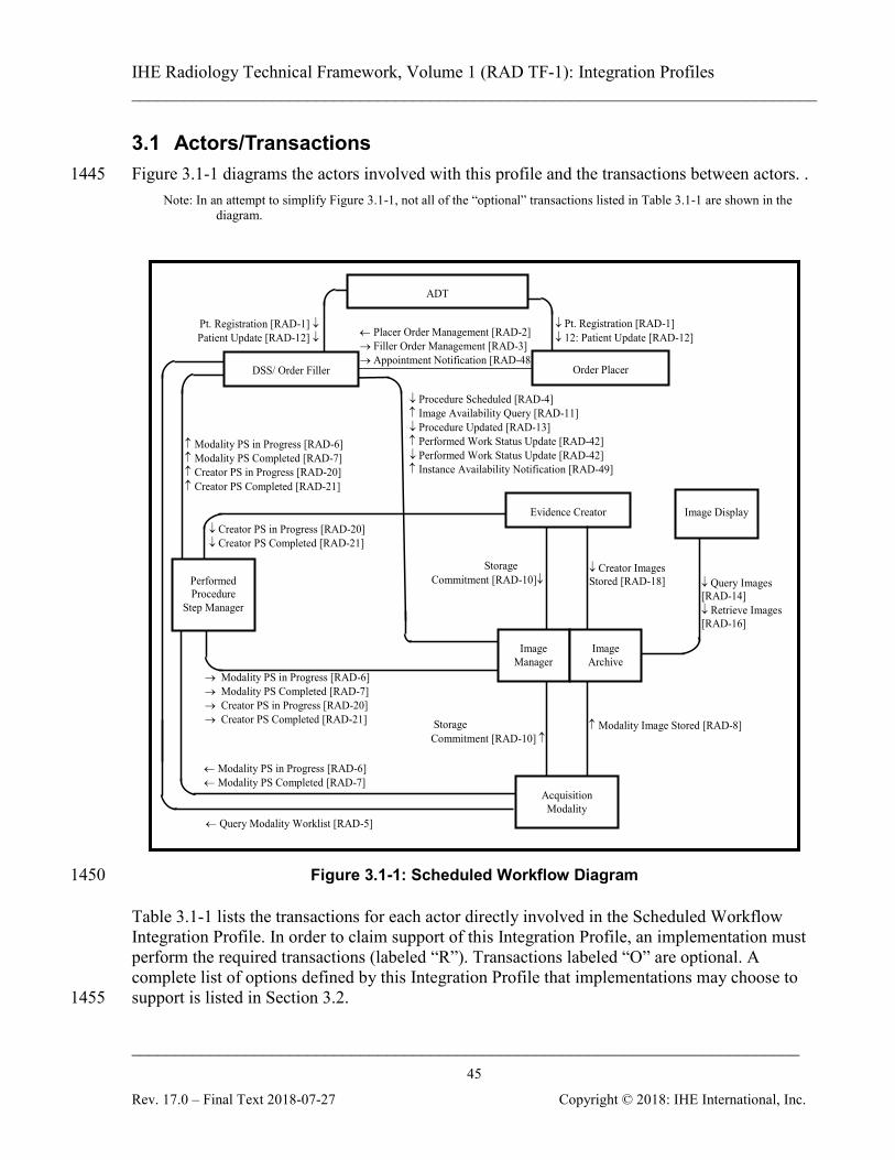
IHE Radiology Technical Framework, Volume 1 (RAD TF-1): Integration Profiles ______________________________________________________________________________
____________________________________________________________________________ 45
Rev. 17.0 – Final Text 2018-07-27 Copyright © 2018: IHE International, Inc.
3.1 Actors/Transactions Figure 3.1-1 diagrams the actors involved with this profile and the transactions between actors. . 1445
Note: In an attempt to simplify Figure 3.1-1, not all of the “optional” transactions listed in Table 3.1-1 are shown in the diagram.
↓ Pt. Registration [RAD-1] ↓ 12: Patient Update [RAD-12]
Pt. Registration [RAD-1] ↓ Patient Update [RAD-12] ↓ ← Placer Order Management [RAD-2]
→ Filler Order Management [RAD-3] → Appointment Notification [RAD-48]
ADT
↓ Query Images [RAD-14] ↓ Retrieve Images [RAD-16]
Image Display
Storage Commitment [RAD-10]↓
↑ Modality Image Stored [RAD-8] Storage Commitment [RAD-10] ↑
↓ Creator Images Stored [RAD-18]
↓ Procedure Scheduled [RAD-4] ↑ Image Availability Query [RAD-11] ↓ Procedure Updated [RAD-13] ↑ Performed Work Status Update [RAD-42] ↓ Performed Work Status Update [RAD-42] ↑ Instance Availability Notification [RAD-49]
← Query Modality Worklist [RAD-5]
Evidence Creator
Performed Procedure
Step Manager
↑ Modality PS in Progress [RAD-6] ↑ Modality PS Completed [RAD-7] ↑ Creator PS in Progress [RAD-20] ↑ Creator PS Completed [RAD-21]
→ Modality PS in Progress [RAD-6] → Modality PS Completed [RAD-7] → Creator PS in Progress [RAD-20] → Creator PS Completed [RAD-21]
← Modality PS in Progress [RAD-6] ← Modality PS Completed [RAD-7]
↓ Creator PS in Progress [RAD-20] ↓ Creator PS Completed [RAD-21]
Order Placer
Acquisition Modality
Image Manager
Image Archive
DSS/ Order Filler
Figure 3.1-1: Scheduled Workflow Diagram 1450
Table 3.1-1 lists the transactions for each actor directly involved in the Scheduled Workflow Integration Profile. In order to claim support of this Integration Profile, an implementation must perform the required transactions (labeled “R”). Transactions labeled “O” are optional. A complete list of options defined by this Integration Profile that implementations may choose to support is listed in Section 3.2. 1455
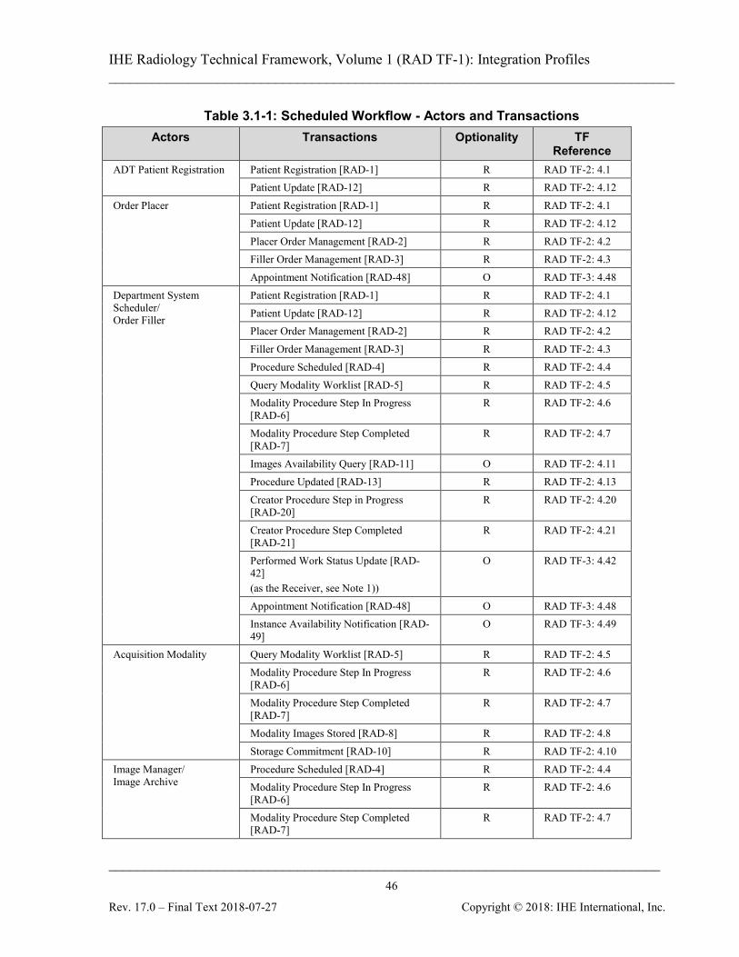
IHE Radiology Technical Framework, Volume 1 (RAD TF-1): Integration Profiles ______________________________________________________________________________
____________________________________________________________________________ 46
Rev. 17.0 – Final Text 2018-07-27 Copyright © 2018: IHE International, Inc.
Table 3.1-1: Scheduled Workflow - Actors and Transactions Actors Transactions Optionality TF
Reference ADT Patient Registration Patient Registration [RAD-1] R RAD TF-2: 4.1
Patient Update [RAD-12] R RAD TF-2: 4.12 Order Placer Patient Registration [RAD-1] R RAD TF-2: 4.1
Patient Update [RAD-12] R RAD TF-2: 4.12 Placer Order Management [RAD-2] R RAD TF-2: 4.2 Filler Order Management [RAD-3] R RAD TF-2: 4.3 Appointment Notification [RAD-48] O RAD TF-3: 4.48
Department System Scheduler/ Order Filler
Patient Registration [RAD-1] R RAD TF-2: 4.1 Patient Update [RAD-12] R RAD TF-2: 4.12 Placer Order Management [RAD-2] R RAD TF-2: 4.2 Filler Order Management [RAD-3] R RAD TF-2: 4.3 Procedure Scheduled [RAD-4] R RAD TF-2: 4.4 Query Modality Worklist [RAD-5] R RAD TF-2: 4.5 Modality Procedure Step In Progress [RAD-6]
R RAD TF-2: 4.6
Modality Procedure Step Completed [RAD-7]
R RAD TF-2: 4.7
Images Availability Query [RAD-11] O RAD TF-2: 4.11 Procedure Updated [RAD-13] R RAD TF-2: 4.13 Creator Procedure Step in Progress [RAD-20]
R RAD TF-2: 4.20
Creator Procedure Step Completed [RAD-21]
R RAD TF-2: 4.21
Performed Work Status Update [RAD-42] (as the Receiver, see Note 1))
O RAD TF-3: 4.42
Appointment Notification [RAD-48] O RAD TF-3: 4.48 Instance Availability Notification [RAD-49]
O RAD TF-3: 4.49
Acquisition Modality Query Modality Worklist [RAD-5] R RAD TF-2: 4.5 Modality Procedure Step In Progress [RAD-6]
R RAD TF-2: 4.6
Modality Procedure Step Completed [RAD-7]
R RAD TF-2: 4.7
Modality Images Stored [RAD-8] R RAD TF-2: 4.8 Storage Commitment [RAD-10] R RAD TF-2: 4.10
Image Manager/ Image Archive
Procedure Scheduled [RAD-4] R RAD TF-2: 4.4 Modality Procedure Step In Progress [RAD-6]
R RAD TF-2: 4.6
Modality Procedure Step Completed [RAD-7]
R RAD TF-2: 4.7
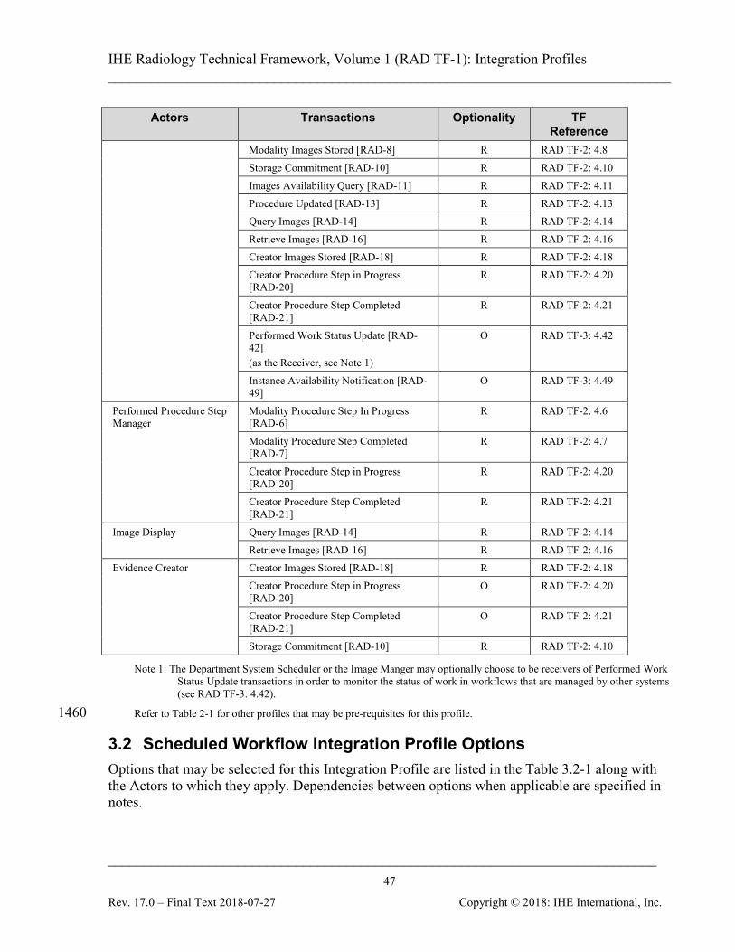
IHE Radiology Technical Framework, Volume 1 (RAD TF-1): Integration Profiles ______________________________________________________________________________
____________________________________________________________________________ 47
Rev. 17.0 – Final Text 2018-07-27 Copyright © 2018: IHE International, Inc.
Actors Transactions Optionality TF Reference
Modality Images Stored [RAD-8] R RAD TF-2: 4.8 Storage Commitment [RAD-10] R RAD TF-2: 4.10 Images Availability Query [RAD-11] R RAD TF-2: 4.11 Procedure Updated [RAD-13] R RAD TF-2: 4.13 Query Images [RAD-14] R RAD TF-2: 4.14 Retrieve Images [RAD-16] R RAD TF-2: 4.16 Creator Images Stored [RAD-18] R RAD TF-2: 4.18 Creator Procedure Step in Progress [RAD-20]
R RAD TF-2: 4.20
Creator Procedure Step Completed [RAD-21]
R RAD TF-2: 4.21
Performed Work Status Update [RAD-42] (as the Receiver, see Note 1)
O RAD TF-3: 4.42
Instance Availability Notification [RAD-49]
O RAD TF-3: 4.49
Performed Procedure Step Manager
Modality Procedure Step In Progress [RAD-6]
R RAD TF-2: 4.6
Modality Procedure Step Completed [RAD-7]
R RAD TF-2: 4.7
Creator Procedure Step in Progress [RAD-20]
R RAD TF-2: 4.20
Creator Procedure Step Completed [RAD-21]
R RAD TF-2: 4.21
Image Display Query Images [RAD-14] R RAD TF-2: 4.14 Retrieve Images [RAD-16] R RAD TF-2: 4.16
Evidence Creator Creator Images Stored [RAD-18] R RAD TF-2: 4.18 Creator Procedure Step in Progress [RAD-20]
O RAD TF-2: 4.20
Creator Procedure Step Completed [RAD-21]
O RAD TF-2: 4.21
Storage Commitment [RAD-10] R RAD TF-2: 4.10
Note 1: The Department System Scheduler or the Image Manger may optionally choose to be receivers of Performed Work Status Update transactions in order to monitor the status of work in workflows that are managed by other systems (see RAD TF-3: 4.42).
Refer to Table 2-1 for other profiles that may be pre-requisites for this profile. 1460
3.2 Scheduled Workflow Integration Profile Options Options that may be selected for this Integration Profile are listed in the Table 3.2-1 along with the Actors to which they apply. Dependencies between options when applicable are specified in notes.
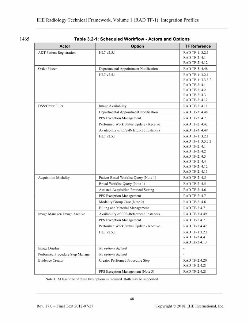
IHE Radiology Technical Framework, Volume 1 (RAD TF-1): Integration Profiles ______________________________________________________________________________
____________________________________________________________________________ 48
Rev. 17.0 – Final Text 2018-07-27 Copyright © 2018: IHE International, Inc.
Table 3.2-1: Scheduled Workflow - Actors and Options 1465 Actor Option TF Reference
ADT Patient Registration HL7 v2.5.1 RAD TF-1: 3.2.1 RAD TF-2: 4.1 RAD TF-2: 4.12
Order Placer Departmental Appointment Notification RAD TF-3: 4.48 HL7 v2.5.1 RAD TF-1: 3.2.1
RAD TF-1: 3.3.3.2 RAD TF-2: 4.1 RAD TF-2: 4.2 RAD TF-2: 4.3 RAD TF-2: 4.12
DSS/Order Filler Image Availability RAD TF-2: 4.11 Departmental Appointment Notification RAD TF-3: 4.48 PPS Exception Management RAD TF-2: 4.7 Performed Work Status Update - Receive RAD TF-2: 4.42 Availability of PPS-Referenced Instances RAD TF-3: 4.49 HL7 v2.5.1 RAD TF-1: 3.2.1
RAD TF-1: 3.3.3.2 RAD TF-2: 4.1 RAD TF-2: 4.2 RAD TF-2: 4.3 RAD TF-2: 4.4 RAD TF-2: 4.12 RAD TF-2: 4.13
Acquisition Modality Patient Based Worklist Query (Note 1) RAD TF-2: 4.5 Broad Worklist Query (Note 1) RAD TF-2: 4.5 Assisted Acquisition Protocol Setting RAD TF-2: 4.6 PPS Exception Management RAD TF-2: 4.7 Modality Group Case (Note 2) RAD TF-2:.4.6 Billing and Material Management RAD TF-2:4.7
Image Manager/ Image Archive Availability of PPS-Referenced Instances RAD TF-3:4.49 PPS Exception Management RAD TF-2:4.7 Performed Work Status Update - Receive RAD TF-2:4.42 HL7 v2.5.1 RAD TF-1:3.2.1
RAD TF-2:4.4 RAD TF-2:4.13
Image Display No options defined - Performed Procedure Step Manager No options defined - Evidence Creator Creator Performed Procedure Step RAD TF-2:4.20
RAD TF-2:4.21 PPS Exception Management (Note 3) RAD TF-2:4.21
Note 1: At least one of these two options is required. Both may be supported.

IHE Radiology Technical Framework, Volume 1 (RAD TF-1): Integration Profiles ______________________________________________________________________________
____________________________________________________________________________ 49
Rev. 17.0 – Final Text 2018-07-27 Copyright © 2018: IHE International, Inc.
Note 2: When a modality claims support for the Modality Group Case Option, it is required to support all three grouping scenarios described in RAD TF-2: 4.6.4.1.2.3.4.
Note 3: An Evidence Creator claiming the PPS Exception Management Option shall also support the Creator Performed Procedure Step Option. 1470
The Evidence Creator, Acquisition Modality and Image Manager/ Image Archive will likely support a variety of DICOM SOP Classes. It is expected that this level of optionality will be documented by a reference in the IHE Integration Statement (see Appendix D).
3.2.1 HL7 v2.5.1 Option The HL7 v2.5.1 Option requires actors to support HL7 v2.5.1 in addition to HL7 v2.3.1 in the 1475 transactions referenced in Table 3.2-1. The actor shall permit configuration for each system that it communicates with using the referenced transactions whether HL7 v2.3.1 or HL7 v2.5.1 is used. It is possible that the actor may receive HL7 v2.3.1 messages and send HL7 v2.5.1 messages or vice versa. The specifications in the HL7 v2.5.1 Option maintain semantic equivalency with HL7 v2.3.1 1480 implementations and the field correspondences are summarized in RAD TF-2: Appendix E.
3.3 Scheduled Workflow Process Flow This section describes the process and information flow of patient care as it is defined in the Radiology Technical Framework under “normal” circumstances. It covers transactions [RAD-1] through [RAD-12] and transaction [RAD-23], which reflect a typical patient encounter from 1485 registration/admission through the performance of an ordered procedure. See appendix C for an overview of the information exchange between the Department System Scheduler/Order Filler and Image Manager. To support the Scheduled Workflow Profile, an actor that claims support of other content profiles (Consistent Presentation of Images, Key Image Notes or Evidence Documents) is 1490 required to support the relevant storage, query and retrieve transactions and manage creation of those objects in the same way images are supported. The following diagrams will mostly show the management of images.
3.3.1 Administrative and Procedure Performance Process Flow This case covers both inpatient and outpatient procedures. The patient may be new or known to 1495 the current healthcare facility. The following sequence of steps describes the typical process flow when a request is made to perform an imaging procedure on a patient.
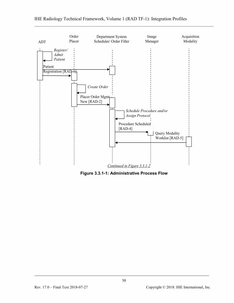
IHE Radiology Technical Framework, Volume 1 (RAD TF-1): Integration Profiles ______________________________________________________________________________
____________________________________________________________________________ 50
Rev. 17.0 – Final Text 2018-07-27 Copyright © 2018: IHE International, Inc.
Query Modality Worklist [RAD-5]
ADT Order Placer
Image Manager
Acquisition Modality
Placer Order Mgmt – New [RAD-2]
Department System Scheduler/ Order Filler
Procedure Scheduled [RAD-4]
Register/Admit Patient
Create Order
Schedule Procedure and/or Assign Protocol
Continued in Figure 3.3.1-2
Patient Registration [RAD-1]
Figure 3.3.1-1: Administrative Process Flow
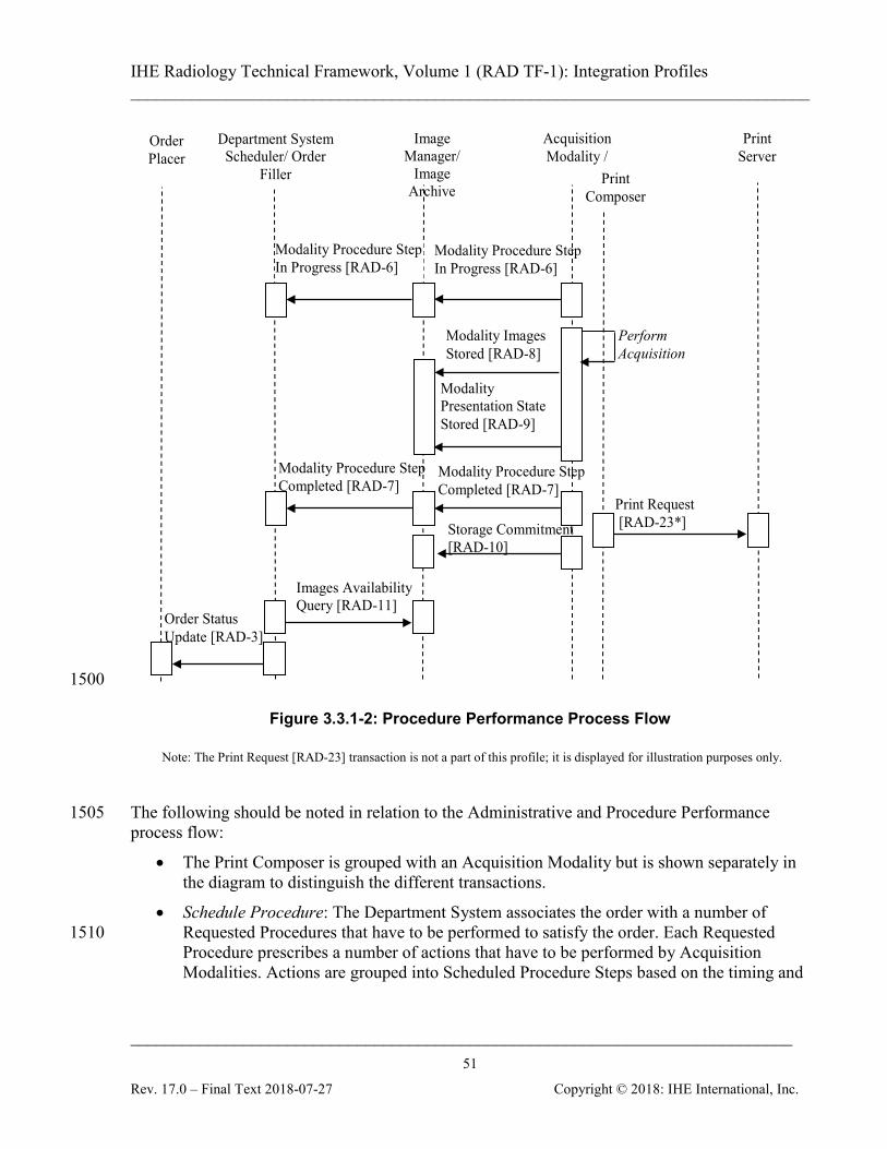
IHE Radiology Technical Framework, Volume 1 (RAD TF-1): Integration Profiles ______________________________________________________________________________
____________________________________________________________________________ 51
Rev. 17.0 – Final Text 2018-07-27 Copyright © 2018: IHE International, Inc.
Image Manager/
Image Archive
Acquisition Modality /
Department System Scheduler/ Order
Filler
Modality Procedure Step Completed [RAD-7]
Perform Acquisition
Modality Images Stored [RAD-8]
Modality Presentation State Stored [RAD-9]
Storage Commitment [RAD-10]
Modality Procedure Step In Progress [RAD-6]
Images Availability Query [RAD-11]
Modality Procedure Step Completed [RAD-7]
Modality Procedure Step In Progress [RAD-6]
Print Composer
Print Request [RAD-23*]
Print Server
Order Placer
Order Status Update [RAD-3]
1500
Figure 3.3.1-2: Procedure Performance Process Flow
Note: The Print Request [RAD-23] transaction is not a part of this profile; it is displayed for illustration purposes only.
The following should be noted in relation to the Administrative and Procedure Performance 1505 process flow:
• The Print Composer is grouped with an Acquisition Modality but is shown separately in the diagram to distinguish the different transactions.
• Schedule Procedure: The Department System associates the order with a number of Requested Procedures that have to be performed to satisfy the order. Each Requested 1510 Procedure prescribes a number of actions that have to be performed by Acquisition Modalities. Actions are grouped into Scheduled Procedure Steps based on the timing and

IHE Radiology Technical Framework, Volume 1 (RAD TF-1): Integration Profiles ______________________________________________________________________________
____________________________________________________________________________ 52
Rev. 17.0 – Final Text 2018-07-27 Copyright © 2018: IHE International, Inc.
ordering. Scheduled Procedure Steps are scheduled, i.e., assigned a time slot and performing resource (modality).
• Protocol Assigned: The radiologist determines the protocol (i.e., settings and conditions 1515 to be used in performing the Scheduled Procedure Steps); in particular, the ordered list of codes identifying the protocol for each of the steps. This may happen prior to, simultaneous with, or subsequent to the Schedule Procedure process step.
• The diagram above shows one particular sequencing of the Modality Procedure Step Completed [RAD-7] transaction. This transaction may occur at any point following the 1520 creation of an image and/or Presentation State (GSPS) objects. This means it can occur before images and/or GSPS are stored, after storage, after printing (as in this example), or even after storage commitment. The Radiology Technical Framework does not specify the timing of this transaction in relation to other transactions.
• The diagram above shows the managed creation of images. The equivalent flow applies 1525 to other Evidence Documents that the actor supports.
3.3.2 Patient Update Flow This case covers the situation where patient information updates are introduced into the system at the various stages of the normal process flow. Such updates will cause additional transactions to occur to assure synchronization of information between interested actors. Only the affected parts 1530 of the normal flow diagram are presented below. All subsequent process steps will progress according to the normal flow diagram.
3.3.2.1 Patient Update before Procedure Scheduling If patient information is changed before the corresponding procedure(s) are scheduled by the Department System Scheduler/Order Filler, the Patient Registration steps are altered as presented 1535 in the Figures 3.3.2.1-1 and 3.3.2.1-2.

IHE Radiology Technical Framework, Volume 1 (RAD TF-1): Integration Profiles ______________________________________________________________________________
____________________________________________________________________________ 53
Rev. 17.0 – Final Text 2018-07-27 Copyright © 2018: IHE International, Inc.
ADT
Order Placer
Image Manager
Acquisition Modality
Placer Order Mgmt – New [RAD-2]
Department System Scheduler/ Order Filler
Register/ Admit Patient
Create Order
Modify Patient
Patient Registration [RAD-1]
Patient Update [RAD-12]
Figure 3.3.2.1-1: Patient Update before Order Entry
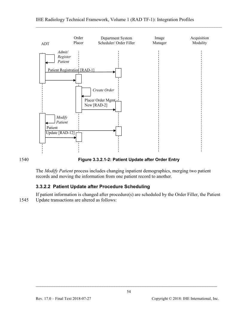
IHE Radiology Technical Framework, Volume 1 (RAD TF-1): Integration Profiles ______________________________________________________________________________
____________________________________________________________________________ 54
Rev. 17.0 – Final Text 2018-07-27 Copyright © 2018: IHE International, Inc.
ADT
Order Placer
Image Manager
Acquisition Modality
Placer Order Mgmt – New [RAD-2]
Department System Scheduler/ Order Filler
Admit/ Register Patient
Create Order
Modify Patient
Patient Update [RAD-12]
Patient Registration [RAD-1]
Figure 3.3.2.1-2: Patient Update after Order Entry 1540
The Modify Patient process includes changing inpatient demographics, merging two patient records and moving the information from one patient record to another.
3.3.2.2 Patient Update after Procedure Scheduling If patient information is changed after procedure(s) are scheduled by the Order Filler, the Patient Update transactions are altered as follows: 1545
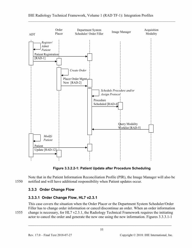
IHE Radiology Technical Framework, Volume 1 (RAD TF-1): Integration Profiles ______________________________________________________________________________
____________________________________________________________________________ 55
Rev. 17.0 – Final Text 2018-07-27 Copyright © 2018: IHE International, Inc.
Query Modality Worklist [RAD-5]
ADT Order Placer Image Manager Acquisition
Modality
Placer Order Mgmt – New [RAD-2]
Department System Scheduler/ Order Filler
Procedure Scheduled [RAD-4]
Register/Admit Patient
Create Order
Schedule Procedure and/or Assign Protocol
Patient Update [RAD-12]
Modify Patient
Patient Registration [RAD-1]
Figure 3.3.2.2-1: Patient Update after Procedure Scheduling
Note that in the Patient Information Reconciliation Profile (PIR), the Image Manager will also be notified and will have additional responsibility when Patient updates occur. 1550
3.3.3 Order Change Flow
3.3.3.1 Order Change Flow, HL7 v2.3.1 This case covers the situation when the Order Placer or the Department System Scheduler/Order Filler has to change order information or cancel/discontinue an order. When an order information change is necessary, for HL7 v2.3.1, the Radiology Technical Framework requires the initiating 1555 actor to cancel the order and generate the new one using the new information. Figures 3.3.3.1-1
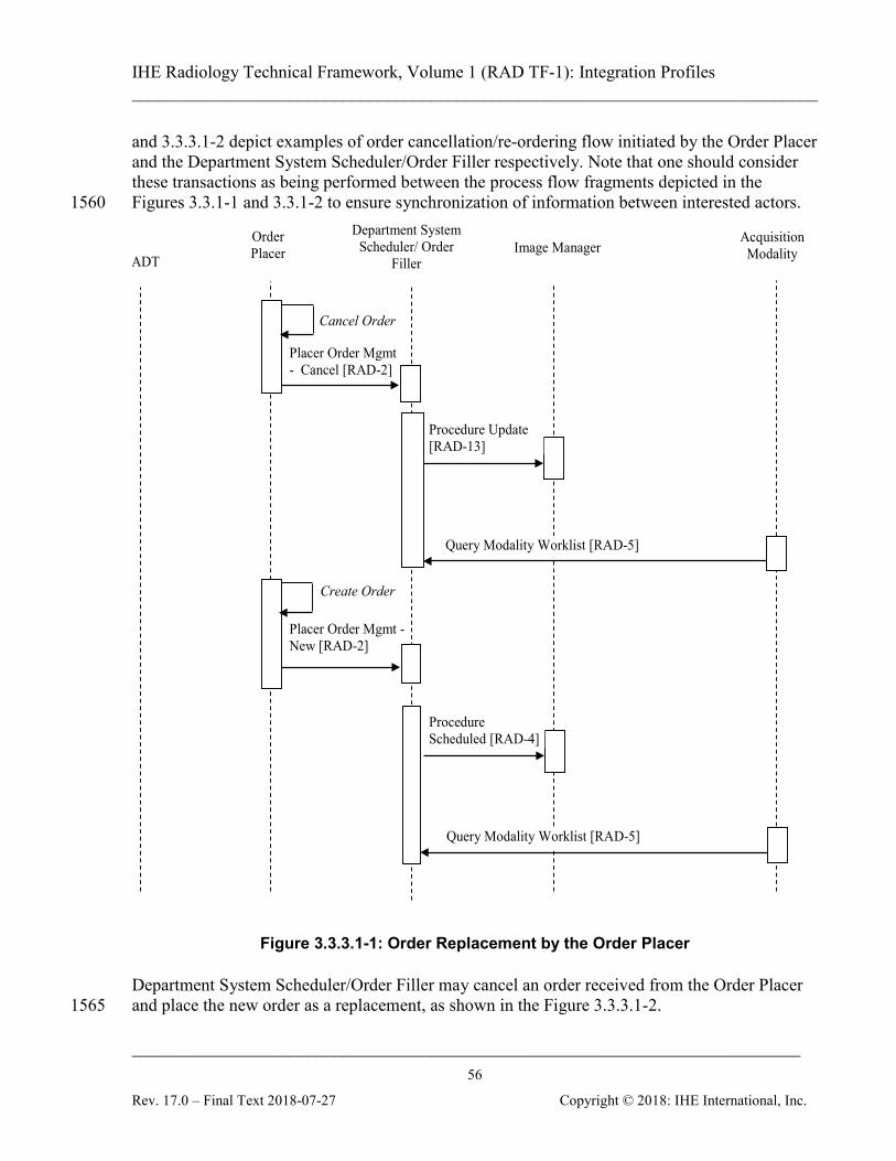
IHE Radiology Technical Framework, Volume 1 (RAD TF-1): Integration Profiles ______________________________________________________________________________
____________________________________________________________________________ 56
Rev. 17.0 – Final Text 2018-07-27 Copyright © 2018: IHE International, Inc.
and 3.3.3.1-2 depict examples of order cancellation/re-ordering flow initiated by the Order Placer and the Department System Scheduler/Order Filler respectively. Note that one should consider these transactions as being performed between the process flow fragments depicted in the Figures 3.3.1-1 and 3.3.1-2 to ensure synchronization of information between interested actors. 1560
Query Modality Worklist [RAD-5]
ADT
Order Placer Image Manager
Acquisition Modality
Placer Order Mgmt - Cancel [RAD-2]
Department System Scheduler/ Order
Filler
Procedure Update [RAD-13]
Cancel Order
Query Modality Worklist [RAD-5]
Procedure Scheduled [RAD-4]
Create Order
Placer Order Mgmt - New [RAD-2]
Figure 3.3.3.1-1: Order Replacement by the Order Placer
Department System Scheduler/Order Filler may cancel an order received from the Order Placer and place the new order as a replacement, as shown in the Figure 3.3.3.1-2. 1565
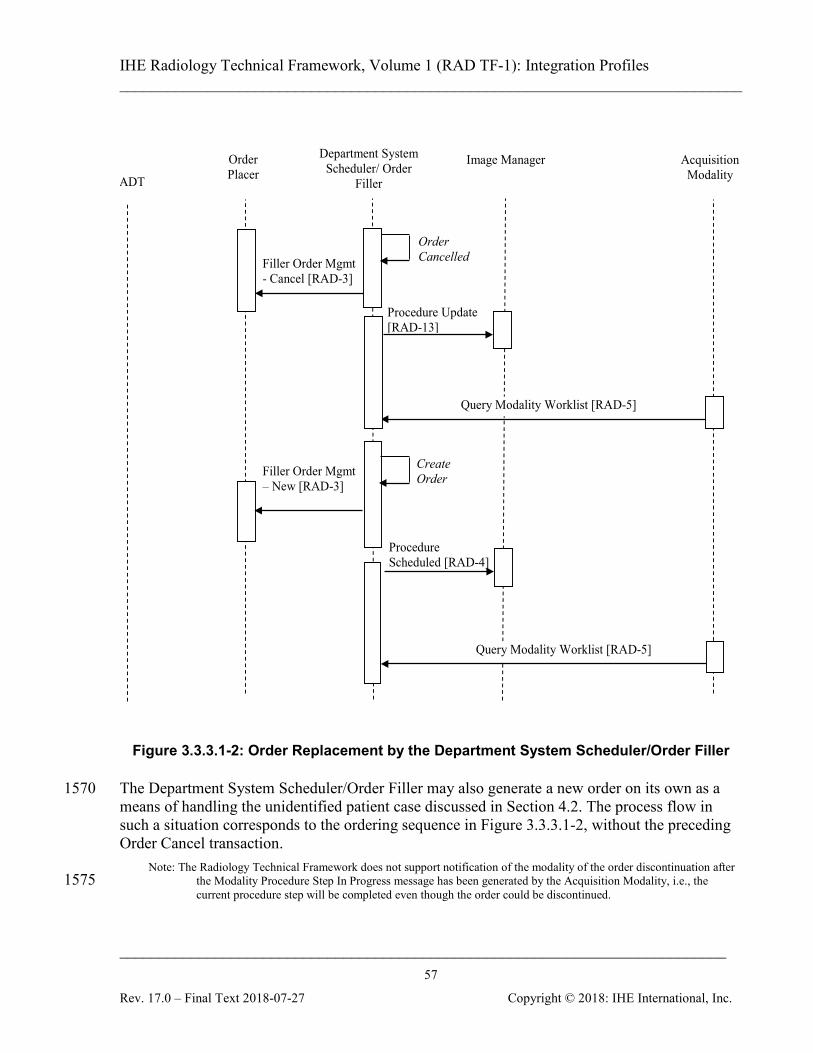
IHE Radiology Technical Framework, Volume 1 (RAD TF-1): Integration Profiles ______________________________________________________________________________
____________________________________________________________________________ 57
Rev. 17.0 – Final Text 2018-07-27 Copyright © 2018: IHE International, Inc.
Query Modality Worklist [RAD-5]
ADT
Order Placer
Image Manager Acquisition Modality
Department System Scheduler/ Order
Filler
Procedure Update [RAD-13]
Filler Order Mgmt - Cancel [RAD-3]
Procedure Scheduled [RAD-4]
Order Cancelled
Filler Order Mgmt – New [RAD-3]
Create Order
Query Modality Worklist [RAD-5]
Figure 3.3.3.1-2: Order Replacement by the Department System Scheduler/Order Filler
The Department System Scheduler/Order Filler may also generate a new order on its own as a 1570 means of handling the unidentified patient case discussed in Section 4.2. The process flow in such a situation corresponds to the ordering sequence in Figure 3.3.3.1-2, without the preceding Order Cancel transaction.
Note: The Radiology Technical Framework does not support notification of the modality of the order discontinuation after the Modality Procedure Step In Progress message has been generated by the Acquisition Modality, i.e., the 1575 current procedure step will be completed even though the order could be discontinued.
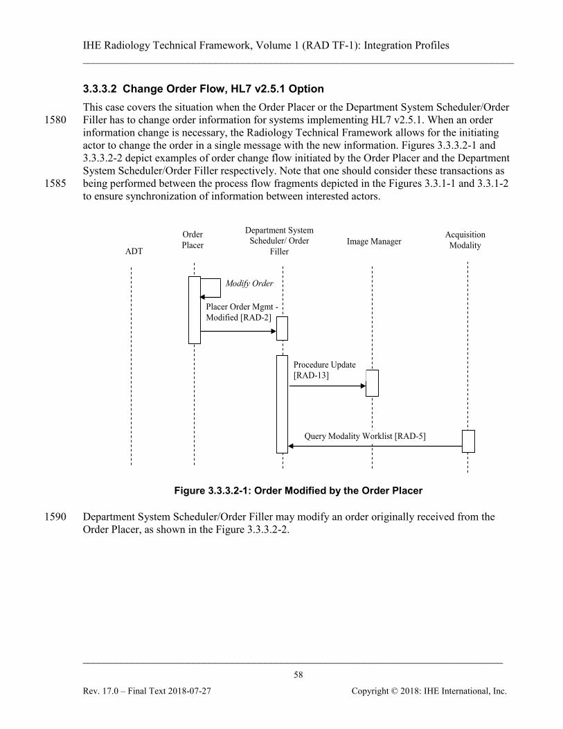
IHE Radiology Technical Framework, Volume 1 (RAD TF-1): Integration Profiles ______________________________________________________________________________
____________________________________________________________________________ 58
Rev. 17.0 – Final Text 2018-07-27 Copyright © 2018: IHE International, Inc.
3.3.3.2 Change Order Flow, HL7 v2.5.1 Option This case covers the situation when the Order Placer or the Department System Scheduler/Order Filler has to change order information for systems implementing HL7 v2.5.1. When an order 1580 information change is necessary, the Radiology Technical Framework allows for the initiating actor to change the order in a single message with the new information. Figures 3.3.3.2-1 and 3.3.3.2-2 depict examples of order change flow initiated by the Order Placer and the Department System Scheduler/Order Filler respectively. Note that one should consider these transactions as being performed between the process flow fragments depicted in the Figures 3.3.1-1 and 3.3.1-2 1585 to ensure synchronization of information between interested actors.
Figure 3.3.3.2-1: Order Modified by the Order Placer
Department System Scheduler/Order Filler may modify an order originally received from the 1590 Order Placer, as shown in the Figure 3.3.3.2-2.
Order Placer Image Manager
Acquisition Modality
Department System Scheduler/ Order
Filler
Query Modality Worklist [RAD-5]
Procedure Update [RAD-13]
Modify Order
Placer Order Mgmt - Modified [RAD-2]
ADT
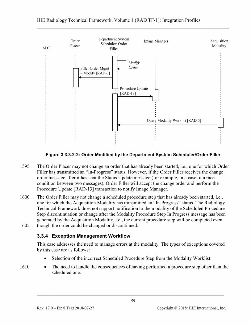
IHE Radiology Technical Framework, Volume 1 (RAD TF-1): Integration Profiles ______________________________________________________________________________
____________________________________________________________________________ 59
Rev. 17.0 – Final Text 2018-07-27 Copyright © 2018: IHE International, Inc.
Figure 3.3.3.2-2: Order Modified by the Department System Scheduler/Order Filler
The Order Placer may not change an order that has already been started, i.e., one for which Order 1595 Filler has transmitted an “In-Progress” status. However, if the Order Filler receives the change order message after it has sent the Status Update message (for example, in a case of a race condition between two messages), Order Filler will accept the change order and perform the Procedure Update [RAD-13] transaction to notify Image Manager. The Order Filler may not change a scheduled procedure step that has already been started, i.e., 1600 one for which the Acquisition Modality has transmitted an “In-Progress” status. The Radiology Technical Framework does not support notification to the modality of the Scheduled Procedure Step discontinuation or change after the Modality Procedure Step In Progress message has been generated by the Acquisition Modality, i.e., the current procedure step will be completed even though the order could be changed or discontinued. 1605
3.3.4 Exception Management Workflow This case addresses the need to manage errors at the modality. The types of exceptions covered by this case are as follows:
• Selection of the incorrect Scheduled Procedure Step from the Modality Worklist.
• The need to handle the consequences of having performed a procedure step other than the 1610 scheduled one.
ADT
Order Placer
Image Manager Acquisition Modality
Department System Scheduler/ Order
Filler
Procedure Update [RAD-13]
Filler Order Mgmt – Modify [RAD-3]
Modify Order
Query Modality Worklist [RAD-5]
IHE Radiology Technical Framework, Volume 1 (RAD TF-1): Integration Profiles ______________________________________________________________________________
____________________________________________________________________________ 60
Rev. 17.0 – Final Text 2018-07-27 Copyright © 2018: IHE International, Inc.
Some of these exception cases are addressed using required functionality for IHE actors in the Scheduled Workflow Profile and are described first in this section. Other exception cases are listed separately in this section and this Exception Management Workflow is supported by the PPS EXCEPTION MANAGEMENT Option or other options in the Scheduled Workflow 1615 Integration Profile. The following numbered items list exception cases that shall be supported by the actors listed in each item. In the course of the scheduled workflow, such exceptions may occur at different times: 1. Before the Modality Procedure Step in Progress transaction is issued, the
Operator/Radiologist changes the order on the Department System Scheduler which then 1620 provides the Modality Worklist as defined by the Scheduled Workflow Integration Profile (see the Order Change flow described in Section 3.3.3). This will ensure that the most recent Worklist Information is used by the Modality. This case does not require the PPS EXCEPTION MANAGEMENT OPTION. The Acquisition Modality shall be able to process new worklist information that results from this order change; when or how the modality re-1625 queries the Department System Scheduler is not specified by this framework.
2. After the Modality Procedure Step in Progress transaction has been issued, but before the Modality Procedure Step Completed transaction is issued, the Operator/Radiologist may discontinue the PPS. In this case any images that may have been acquired are part of the discontinued PPS and they shall be Storage Committed. This case is supported by 1630 Abandoned case (see RAD TF-2: 4.6.4.1.2.3.5) of the Scheduled Workflow Integration Profile. See the end of this section for discussion of this case and PPS EXCEPTION MANAGEMENT Option.
3. After the Modality Procedure Step Completed transaction has been issued, the Operator/Radiologist may notice or become aware that an incorrect worklist entry selection 1635 was made. Whether this occurs before the Requested Procedure is read or afterwards, the modality is not responsible for performing the necessary corrections. Rather the Image Manager and the Department Scheduler Actors must make such corrections (see RAD TF-2: 4.7.4.1.3.1). The Image Manager and the Order Filler may also offer a correction capability to recover the erroneous instances. IHE does not provide a mechanism to propagate 1640 automatically this correction between the Image Manager/Image Archive and the Department System Scheduler/Order Filler.
These next cases are optional for Acquisition Modalities and deal with using a different protocol at the modality as was scheduled by the Department System Scheduler/ Order Filler. 1. After the Modality Procedure Step in Progress transaction has been issued, but before the 1645
Modality Procedure Step Completed transaction is issued, the Operator/Radiologist may decide to modify the “in progress” Performed Procedure Step from what was intended by the Requested Procedure and Scheduled Procedure Step selected. In the Scheduled Workflow Integration Profile, the Acquisition Modality Actor notifies the PPS Manager (and in turn the Image Manager and the Department System Scheduler) by returning a Procedure Code 1650 Sequence of zero length. In addition, if the ASSISTED ACQUISITION PROTOCOL SETTING Option is supported by the Acquisition Modality, it can indicate this change by
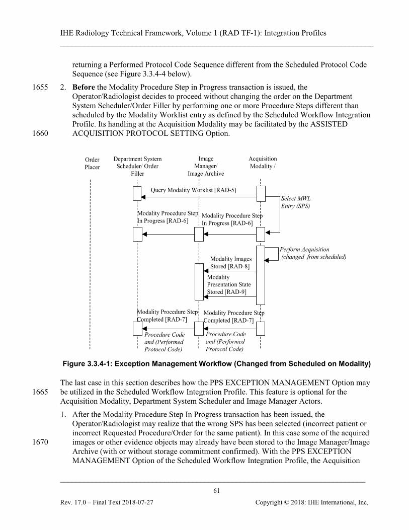
IHE Radiology Technical Framework, Volume 1 (RAD TF-1): Integration Profiles ______________________________________________________________________________
____________________________________________________________________________ 61
Rev. 17.0 – Final Text 2018-07-27 Copyright © 2018: IHE International, Inc.
returning a Performed Protocol Code Sequence different from the Scheduled Protocol Code Sequence (see Figure 3.3.4-4 below).
2. Before the Modality Procedure Step in Progress transaction is issued, the 1655 Operator/Radiologist decides to proceed without changing the order on the Department System Scheduler/Order Filler by performing one or more Procedure Steps different than scheduled by the Modality Worklist entry as defined by the Scheduled Workflow Integration Profile. Its handling at the Acquisition Modality may be facilitated by the ASSISTED ACQUISITION PROTOCOL SETTING Option. 1660
Image
Manager/ Image Archive
Acquisition Modality /
Department System Scheduler/ Order
Filler
Modality Procedure Step Completed [RAD-7]
Perform Acquisition (changed from scheduled) Modality Images
Stored [RAD-8]
Modality Presentation State Stored [RAD-9]
Modality Procedure Step In Progress [RAD-6]
Order Placer
Query Modality Worklist [RAD-5] Select MWL Entry (SPS)
Procedure Code and (Performed Protocol Code)
Procedure Code and (Performed Protocol Code)
Modality Procedure Step In Progress [RAD-6]
Modality Procedure Step Completed [RAD-7]
Figure 3.3.4-1: Exception Management Workflow (Changed from Scheduled on Modality)
The last case in this section describes how the PPS EXCEPTION MANAGEMENT Option may be utilized in the Scheduled Workflow Integration Profile. This feature is optional for the 1665 Acquisition Modality, Department System Scheduler and Image Manager Actors. 1. After the Modality Procedure Step In Progress transaction has been issued, the
Operator/Radiologist may realize that the wrong SPS has been selected (incorrect patient or incorrect Requested Procedure/Order for the same patient). In this case some of the acquired images or other evidence objects may already have been stored to the Image Manager/Image 1670 Archive (with or without storage commitment confirmed). With the PPS EXCEPTION MANAGEMENT Option of the Scheduled Workflow Integration Profile, the Acquisition
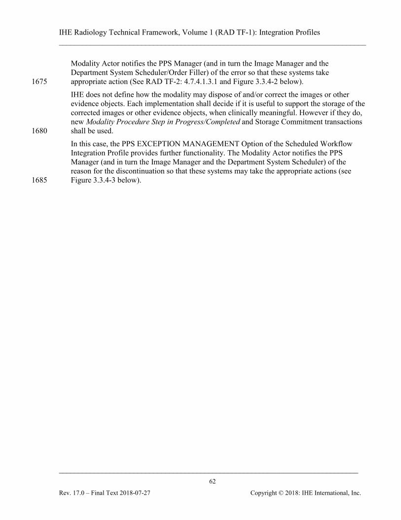
IHE Radiology Technical Framework, Volume 1 (RAD TF-1): Integration Profiles ______________________________________________________________________________
____________________________________________________________________________ 62
Rev. 17.0 – Final Text 2018-07-27 Copyright © 2018: IHE International, Inc.
Modality Actor notifies the PPS Manager (and in turn the Image Manager and the Department System Scheduler/Order Filler) of the error so that these systems take appropriate action (See RAD TF-2: 4.7.4.1.3.1 and Figure 3.3.4-2 below). 1675 IHE does not define how the modality may dispose of and/or correct the images or other evidence objects. Each implementation shall decide if it is useful to support the storage of the corrected images or other evidence objects, when clinically meaningful. However if they do, new Modality Procedure Step in Progress/Completed and Storage Commitment transactions shall be used. 1680 In this case, the PPS EXCEPTION MANAGEMENT Option of the Scheduled Workflow Integration Profile provides further functionality. The Modality Actor notifies the PPS Manager (and in turn the Image Manager and the Department System Scheduler) of the reason for the discontinuation so that these systems may take the appropriate actions (see Figure 3.3.4-3 below). 1685
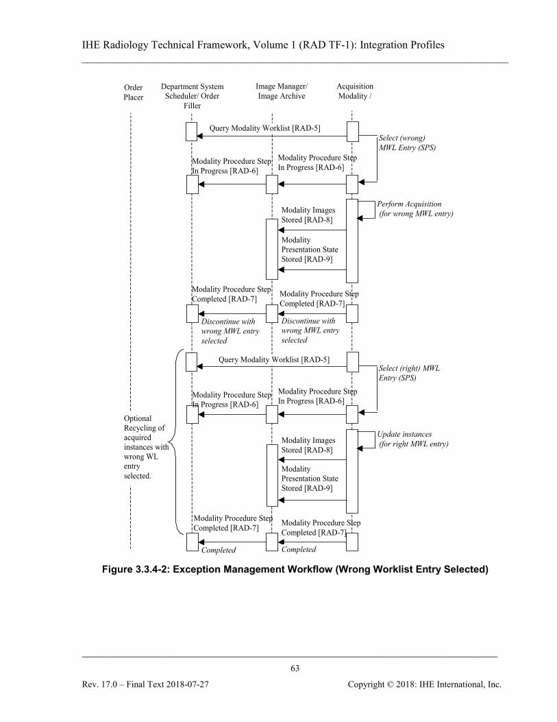
IHE Radiology Technical Framework, Volume 1 (RAD TF-1): Integration Profiles ______________________________________________________________________________
____________________________________________________________________________ 63
Rev. 17.0 – Final Text 2018-07-27 Copyright © 2018: IHE International, Inc.
Image Manager/ Image Archive
Acquisition Modality /
Department System Scheduler/ Order
Filler
Perform Acquisition (for wrong MWL entry) Modality Images
Stored [RAD-8]
Modality Presentation State Stored [RAD-9]
Modality Procedure Step Completed [RAD-7]
Modality Procedure Step In Progress [RAD-6]
Order Placer
Query Modality Worklist [RAD-5] Select (wrong) MWL Entry (SPS)
Discontinue with wrong MWL entry selected
Discontinue with wrong MWL entry selected
Update instances (for right MWL entry) Modality Images
Stored [RAD-8]
Modality Presentation State Stored [RAD-9]
Select (right) MWL Entry (SPS)
Completed Completed
Optional Recycling of acquired instances with wrong WL entry selected.
Modality Procedure Step In Progress [RAD-6]
Modality Procedure Step Completed [RAD-7]
Query Modality Worklist [RAD-5]
Modality Procedure Step In Progress [RAD-6]
Modality Procedure Step In Progress [RAD-6]
Modality Procedure Step Completed [RAD-7]
Modality Procedure Step Completed [RAD-7]
Figure 3.3.4-2: Exception Management Workflow (Wrong Worklist Entry Selected)
IHE Radiology Technical Framework, Volume 1 (RAD TF-1): Integration Profiles ______________________________________________________________________________
____________________________________________________________________________ 64
Rev. 17.0 – Final Text 2018-07-27 Copyright © 2018: IHE International, Inc.
Image Manager/
Image Archive
Acquisition Modality /
Department System Scheduler/ Order
Filler
Modality Procedure Step Completed [RAD-7]
Perform Acquisition (PPS Discontinued) Modality Images
Stored [RAD-8]
Modality Presentation State Stored [RAD-9]
Modality Procedure Step In Progress [RAD-6]
Order Placer
Query Modality Worklist [RAD-5] Select MWL Entry (SPS)
Reason for Discontinue
Reason for Discontinue
Modality Procedure Step In Progress [RAD-6]
Modality Procedure Step Completed [RAD-7]
Figure 3.3.4-3: Exception Management Workflow (Discontinued with a Reason) 1690
3.3.5 Implicit Post-Processing This case addresses image post-processing tasks performed as an implicit part of the Scheduled Workflow. In general, post-processing tasks scheduled and managed explicitly using post processing worklists are addressed by the Post-Processing Workflow Integration Profile (see Section 12 for 1695 further details on that profile). However, at some sites, post-processing tasks performed on the acquisition system or adjacent workstations are implied by the information in the acquisition worklist. In such cases, the post-processing is managed by the technician simply carrying out the steps following acquisition. Technicians may be instructed that certain post-processing should always be performed for 1700 certain acquisitions, or alternatively, different protocol codes may be provided in the acquisition worklist to indicate intended post-processing. In either case, no worklist is used on the post-processing Evidence Creator. In the case of this “implicit post-processing workflow”, the Evidence Creator may obtain source images and other evidence objects necessary for post-processing by receiving them from the 1705 Acquisition Modality Actor (either pulled or pushed via some non-IHE defined mechanism) or by being grouped with an Image Display Actor (giving the system query/retrieve capabilities).
IHE Radiology Technical Framework, Volume 1 (RAD TF-1): Integration Profiles ______________________________________________________________________________
____________________________________________________________________________ 65
Rev. 17.0 – Final Text 2018-07-27 Copyright © 2018: IHE International, Inc.
Based on the information contained in the images, the Evidence Creator can send status messages and store its results according to the IHE transactions as shown in the following use cases. 1710 The following sequence of steps describes the typical process flow when the Evidence Creator receives the images from an Acquisition Modality via some non-IHE means.
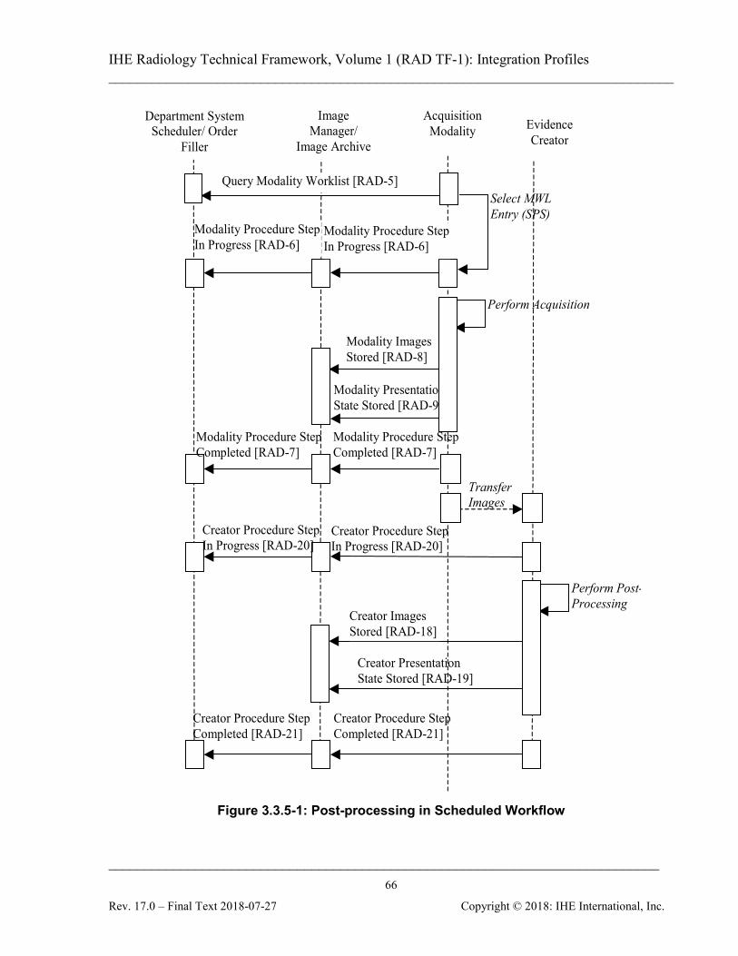
IHE Radiology Technical Framework, Volume 1 (RAD TF-1): Integration Profiles ______________________________________________________________________________
____________________________________________________________________________ 66
Rev. 17.0 – Final Text 2018-07-27 Copyright © 2018: IHE International, Inc.
Image Manager/
Image Archive
Department System Scheduler/ Order
Filler
Perform Acquisition
Modality Images Stored [RAD-8]
Modality Presentation State Stored [RAD-9]
Modality Procedure Step In Progress [RAD-6]
Modality Procedure Step Completed [RAD-7]
Query Modality Worklist [RAD-5] Select MWL Entry (SPS)
Evidence Creator
Perform Post-Processing
Creator Images Stored [RAD-18]
Creator Presentation State Stored [RAD-19]
Creator Procedure Step Completed [RAD-21]
Creator Procedure Step In Progress [RAD-20]
Acquisition Modality
Transfer Images
Modality Procedure Step In Progress [RAD-6]
Modality Procedure Step Completed [RAD-7]
Creator Procedure Step In Progress [RAD-20]
Creator Procedure Step Completed [RAD-21]
Figure 3.3.5-1: Post-processing in Scheduled Workflow
IHE Radiology Technical Framework, Volume 1 (RAD TF-1): Integration Profiles ______________________________________________________________________________
____________________________________________________________________________ 67
Rev. 17.0 – Final Text 2018-07-27 Copyright © 2018: IHE International, Inc.
Note: The Modality Presentation State Stored [RAD-9] and Creator Presentation State Stored [RAD-19] transactions are 1715 not a part of this profile; they are displayed for illustration purposes only.
The following should be noted in relation to the Post-Processing process flow in Scheduled Workflow as described above:
• The images for post-processing are transferred from the Acquisition Modality to the 1720 Evidence Creator by means that are out of scope of the Radiology Technical Framework.
• Perform Post-Processing: The Evidence Creator uses the source images and/or other evidence objects it receives from the Acquisition Modality to perform post-processing tasks and generate new set(s) of images and/or other evidence documents. It uses information from the source images to populate the newly created objects and the Creator 1725 Performed Procedure Step Messages.
The following sequence of steps describes the typical process flow when Evidence Creator is grouped with Image Display.
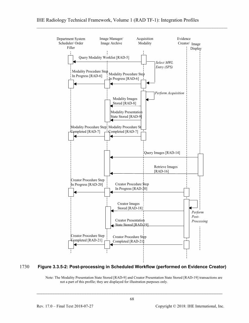
IHE Radiology Technical Framework, Volume 1 (RAD TF-1): Integration Profiles ______________________________________________________________________________
____________________________________________________________________________ 68
Rev. 17.0 – Final Text 2018-07-27 Copyright © 2018: IHE International, Inc.
Image Manager/ Image Archive
Acquisition Modality
Department System Scheduler/ Order
Filler
Perform Acquisition Modality Images
Stored [RAD-8]
Modality Procedure Step In Progress [RAD-6]
Modality Procedure Step Completed [RAD-7]
Query Modality Worklist [RAD-5] Select MWL Entry (SPS)
Evidence Creator/
Perform Post-Processing
Creator Images Stored [RAD-18]
Creator Presentation State Stored [RAD-19]
Creator Procedure Step In Progress [RAD-20]
Query Images [RAD-14]
Retrieve Images [RAD-16]
Modality Presentation State Stored [RAD-9]
Image Display
Modality Procedure Step In Progress [RAD-6]
Modality Procedure Step Completed [RAD-7]
Creator Procedure Step In Progress [RAD-20]
Creator Procedure Step Completed [RAD-21]
Creator Procedure Step Completed [RAD-21]
Figure 3.3.5-2: Post-processing in Scheduled Workflow (performed on Evidence Creator) 1730
Note: The Modality Presentation State Stored [RAD-9] and Creator Presentation State Stored [RAD-19] transactions are not a part of this profile; they are displayed for illustration purposes only.
IHE Radiology Technical Framework, Volume 1 (RAD TF-1): Integration Profiles ______________________________________________________________________________
____________________________________________________________________________ 69
Rev. 17.0 – Final Text 2018-07-27 Copyright © 2018: IHE International, Inc.
The following should be noted in relation to the Post-Processing process flow on the independent workstation:
• The Evidence Creator is grouped with the Image Display and the images for post-1735 processing are retrieved from the Image Archive where the Acquisition Modality has transferred them.
• Perform Post-Processing: The Evidence Creator uses the source images and/or other evidence objects it receives from the Image Archive to perform post-processing tasks and generate new set(s) of images and/or other evidence documents. It uses information from 1740 the source images to populate the newly created objects and the Creator Performed Procedure Step Messages.
3.3.6 Departmental Appointment Booking This case addresses the use of the Departmental Appointment Notification Option by the Order Placer and Order Filler Actors. 1745 Order Fillers that support this option shall have ability to be configured so that the Appointment Notification transaction is not sent when connected to an Order Placer that does not support the Departmental Appointment Notification Option. In the IHE Scheduled Workflow Integration Profile, the scheduling needed to perform an Order is managed by the Departmental System Scheduler/Order Filler. The Order Placer may request 1750 along with an Order a preferred date and time for this Order, but it is the Order Filler that sets, updates and possibly cancels the appointment(s) for examinations. When a new Order is placed by the Order Placer or the Order Filler, an Appointment Notification (New Bookings) is sent to the Order Placer. This Appointment Notification (New Bookings) may include several appointments bookings in case some of the Scheduled Procedure Steps require separate 1755 appointments. Equally, one or more Scheduled Procedure Steps may be scheduled during the same appointment booking. If any changes to some of these appointments are made by the Order Filler, it issues an Appointment Notification (Reschedule Bookings) to inform the Order Placer of the change. If that appointment is cancelled by the Order Filler, it issues an Appointment Notification (Cancel 1760 Bookings) to the Order Placer. This Departmental Appointment Notification Option allows the Order Placer to remain aware of any scheduling changes that may be made by the Order Filler, but not to request an appointment change. For such a change, it may be necessary to use means not defined in this Integration Profile (e.g., a phone call to the person entering orders on the Order Filler) that an appointment 1765 booking has to be changed.
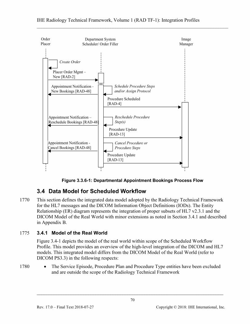
IHE Radiology Technical Framework, Volume 1 (RAD TF-1): Integration Profiles ______________________________________________________________________________
____________________________________________________________________________ 70
Rev. 17.0 – Final Text 2018-07-27 Copyright © 2018: IHE International, Inc.
Order Placer
Image Manager
Placer Order Mgmt – New [RAD-2]
Department System Scheduler/ Order Filler
Procedure Scheduled [RAD-4]
Create Order
Schedule Procedure Steps and/or Assign Protocol
Appointment Notification - New Bookings [RAD-48]
Appointment Notification – Reschedule Bookings [RAD-48]
Reschedule Procedure Step(s)
Cancel Procedure or Procedure Steps
Appointment Notification - Cancel Bookings [RAD-48]
Procedure Update [RAD-13]
Procedure Update [RAD-13]
Figure 3.3.6-1: Departmental Appointment Bookings Process Flow
3.4 Data Model for Scheduled Workflow This section defines the integrated data model adopted by the Radiology Technical Framework 1770 for the HL7 messages and the DICOM Information Object Definitions (IODs). The Entity Relationship (ER) diagram represents the integration of proper subsets of HL7 v2.3.1 and the DICOM Model of the Real World with minor extensions as noted in Section 3.4.1 and described in Appendix B.
3.4.1 Model of the Real World 1775 Figure 3.4-1 depicts the model of the real world within scope of the Scheduled Workflow Profile. This model provides an overview of the high-level integration of the DICOM and HL7 models. This integrated model differs from the DICOM Model of the Real World (refer to DICOM PS3.3) in the following respects:
• The Service Episode, Procedure Plan and Procedure Type entities have been excluded 1780 and are outside the scope of the Radiology Technical Framework
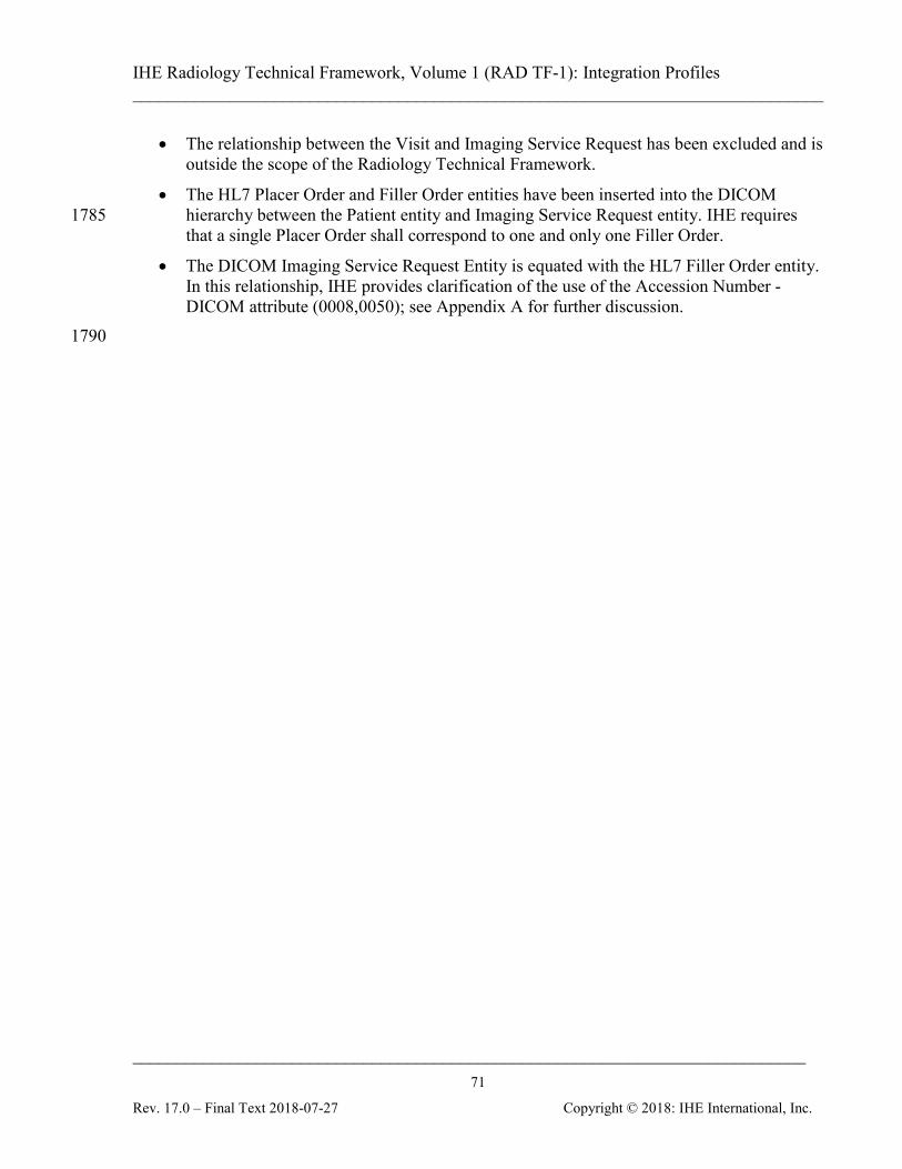
IHE Radiology Technical Framework, Volume 1 (RAD TF-1): Integration Profiles ______________________________________________________________________________
____________________________________________________________________________ 71
Rev. 17.0 – Final Text 2018-07-27 Copyright © 2018: IHE International, Inc.
• The relationship between the Visit and Imaging Service Request has been excluded and is outside the scope of the Radiology Technical Framework.
• The HL7 Placer Order and Filler Order entities have been inserted into the DICOM hierarchy between the Patient entity and Imaging Service Request entity. IHE requires 1785 that a single Placer Order shall correspond to one and only one Filler Order.
• The DICOM Imaging Service Request Entity is equated with the HL7 Filler Order entity. In this relationship, IHE provides clarification of the use of the Accession Number - DICOM attribute (0008,0050); see Appendix A for further discussion.
1790
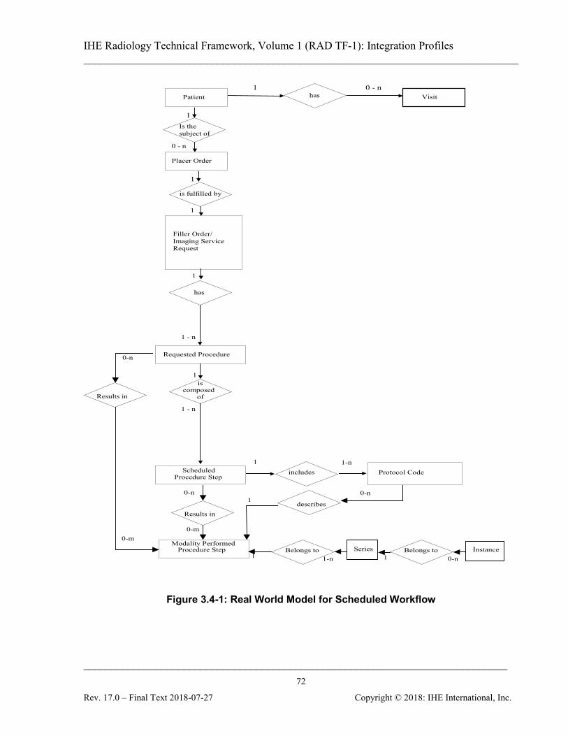
IHE Radiology Technical Framework, Volume 1 (RAD TF-1): Integration Profiles ______________________________________________________________________________
____________________________________________________________________________ 72
Rev. 17.0 – Final Text 2018-07-27 Copyright © 2018: IHE International, Inc.
Requested Procedure
is composed
of
has
1 - n
1
1 - n
Scheduled Procedure Step
includes Protocol Code
1 1-n
Patient 1 0 - n
has Visit
Is the subject of
Placer Order
Filler Order/ Imaging Service Request
1
1
1
0 - n
Modality Performed Procedure Step
Results in
0-m
0-n
describes
0-n 1
Results in
0-n
0-m
Belongs to Belongs to 0-n 1-n
Series Instance 1 1
is fulfilled by
1
Figure 3.4-1: Real World Model for Scheduled Workflow
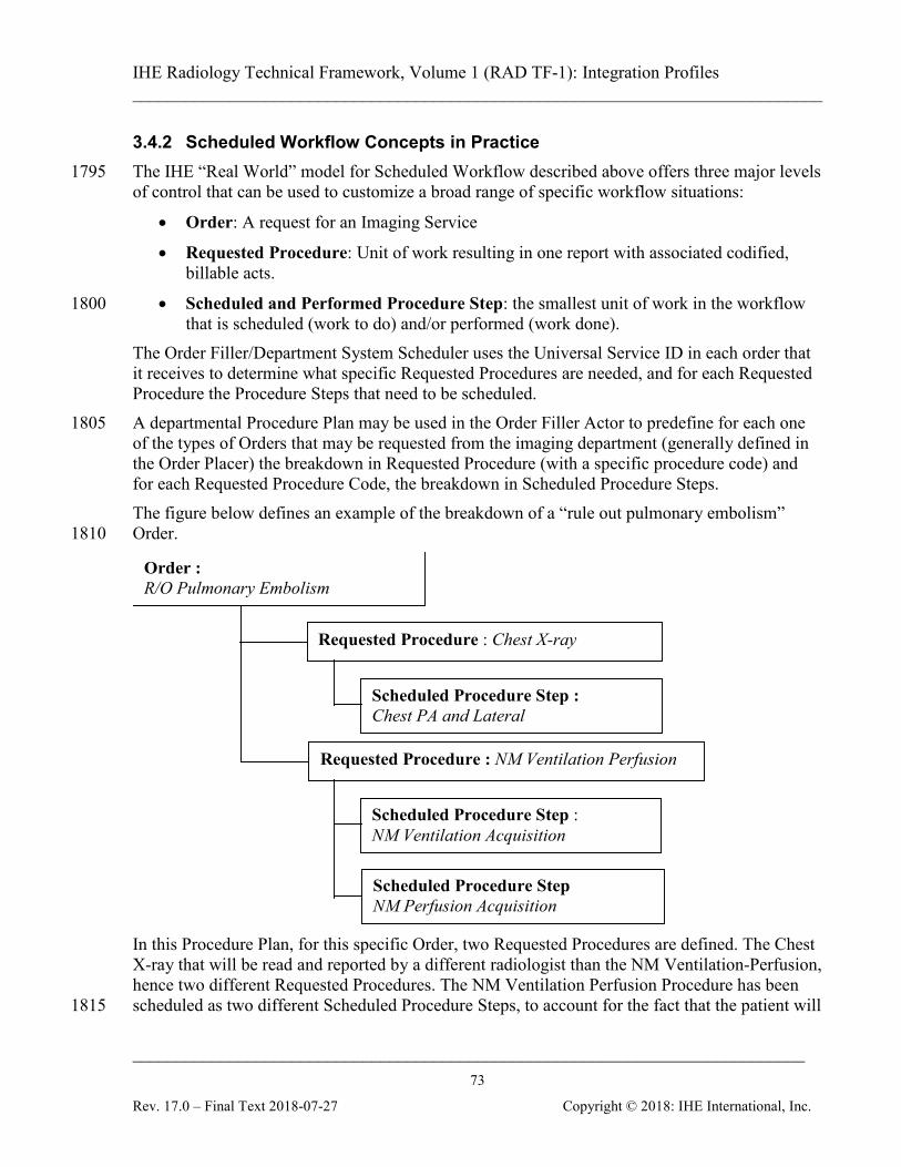
IHE Radiology Technical Framework, Volume 1 (RAD TF-1): Integration Profiles ______________________________________________________________________________
____________________________________________________________________________ 73
Rev. 17.0 – Final Text 2018-07-27 Copyright © 2018: IHE International, Inc.
3.4.2 Scheduled Workflow Concepts in Practice The IHE “Real World” model for Scheduled Workflow described above offers three major levels 1795 of control that can be used to customize a broad range of specific workflow situations:
• Order: A request for an Imaging Service
• Requested Procedure: Unit of work resulting in one report with associated codified, billable acts.
• Scheduled and Performed Procedure Step: the smallest unit of work in the workflow 1800 that is scheduled (work to do) and/or performed (work done).
The Order Filler/Department System Scheduler uses the Universal Service ID in each order that it receives to determine what specific Requested Procedures are needed, and for each Requested Procedure the Procedure Steps that need to be scheduled. A departmental Procedure Plan may be used in the Order Filler Actor to predefine for each one 1805 of the types of Orders that may be requested from the imaging department (generally defined in the Order Placer) the breakdown in Requested Procedure (with a specific procedure code) and for each Requested Procedure Code, the breakdown in Scheduled Procedure Steps. The figure below defines an example of the breakdown of a “rule out pulmonary embolism” Order. 1810
Requested Procedure : Chest X-ray
Order : R/O Pulmonary Embolism
Requested Procedure : NM Ventilation Perfusion
Scheduled Procedure Step : NM Ventilation Acquisition
Scheduled Procedure Step NM Perfusion Acquisition
Scheduled Procedure Step : Chest PA and Lateral
In this Procedure Plan, for this specific Order, two Requested Procedures are defined. The Chest X-ray that will be read and reported by a different radiologist than the NM Ventilation-Perfusion, hence two different Requested Procedures. The NM Ventilation Perfusion Procedure has been scheduled as two different Scheduled Procedure Steps, to account for the fact that the patient will 1815
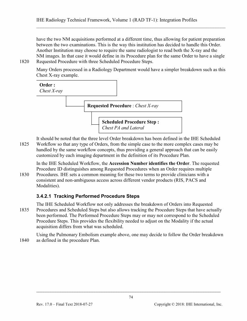
IHE Radiology Technical Framework, Volume 1 (RAD TF-1): Integration Profiles ______________________________________________________________________________
____________________________________________________________________________ 74
Rev. 17.0 – Final Text 2018-07-27 Copyright © 2018: IHE International, Inc.
have the two NM acquisitions performed at a different time, thus allowing for patient preparation between the two examinations. This is the way this institution has decided to handle this Order. Another Institution may choose to require the same radiologist to read both the X-ray and the NM images. In that case it would define in its Procedure plan for the same Order to have a single Requested Procedure with three Scheduled Procedure Steps. 1820 Many Orders processed in a Radiology Department would have a simpler breakdown such as this Chest X-ray example.
Requested Procedure : Chest X-ray
Order : Chest X-ray
Scheduled Procedure Step : Chest PA and Lateral
It should be noted that the three level Order breakdown has been defined in the IHE Scheduled Workflow so that any type of Orders, from the simple case to the more complex cases may be 1825 handled by the same workflow concepts, thus providing a general approach that can be easily customized by each imaging department in the definition of its Procedure Plan. In the IHE Scheduled Workflow, the Accession Number identifies the Order. The requested Procedure ID distinguishes among Requested Procedures when an Order requires multiple Procedures. IHE sets a common meaning for these two terms to provide clinicians with a 1830 consistent and non-ambiguous access across different vendor products (RIS, PACS and Modalities).
3.4.2.1 Tracking Performed Procedure Steps The IHE Scheduled Workflow not only addresses the breakdown of Orders into Requested Procedures and Scheduled Steps but also allows tracking the Procedure Steps that have actually 1835 been performed. The Performed Procedure Steps may or may not correspond to the Scheduled Procedure Steps. This provides the flexibility needed to adjust on the Modality if the actual acquisition differs from what was scheduled. Using the Pulmonary Embolism example above, one may decide to follow the Order breakdown as defined in the procedure Plan. 1840
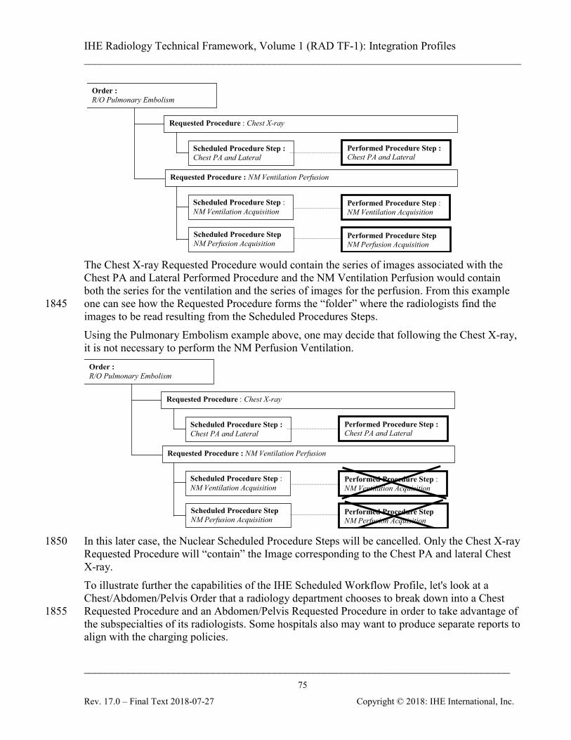
IHE Radiology Technical Framework, Volume 1 (RAD TF-1): Integration Profiles ______________________________________________________________________________
____________________________________________________________________________ 75
Rev. 17.0 – Final Text 2018-07-27 Copyright © 2018: IHE International, Inc.
Requested Procedure : Chest X-ray
Order : R/O Pulmonary Embolism
Requested Procedure : NM Ventilation Perfusion
Scheduled Procedure Step : NM Ventilation Acquisition
Scheduled Procedure Step NM Perfusion Acquisition
Scheduled Procedure Step : Chest PA and Lateral
Performed Procedure Step : Chest PA and Lateral
Performed Procedure Step NM Perfusion Acquisition
Performed Procedure Step : NM Ventilation Acquisition
The Chest X-ray Requested Procedure would contain the series of images associated with the Chest PA and Lateral Performed Procedure and the NM Ventilation Perfusion would contain both the series for the ventilation and the series of images for the perfusion. From this example one can see how the Requested Procedure forms the “folder” where the radiologists find the 1845 images to be read resulting from the Scheduled Procedures Steps. Using the Pulmonary Embolism example above, one may decide that following the Chest X-ray, it is not necessary to perform the NM Perfusion Ventilation.
Requested Procedure : Chest X-ray
Order : R/O Pulmonary Embolism
Requested Procedure : NM Ventilation Perfusion
Scheduled Procedure Step : NM Ventilation Acquisition
Scheduled Procedure Step NM Perfusion Acquisition
Scheduled Procedure Step : Chest PA and Lateral
Performed Procedure Step : Chest PA and Lateral
Performed Procedure Step NM Perfusion Acquisition
Performed Procedure Step : NM Ventilation Acquisition
In this later case, the Nuclear Scheduled Procedure Steps will be cancelled. Only the Chest X-ray 1850 Requested Procedure will “contain” the Image corresponding to the Chest PA and lateral Chest X-ray. To illustrate further the capabilities of the IHE Scheduled Workflow Profile, let's look at a Chest/Abdomen/Pelvis Order that a radiology department chooses to break down into a Chest Requested Procedure and an Abdomen/Pelvis Requested Procedure in order to take advantage of 1855 the subspecialties of its radiologists. Some hospitals also may want to produce separate reports to align with the charging policies.
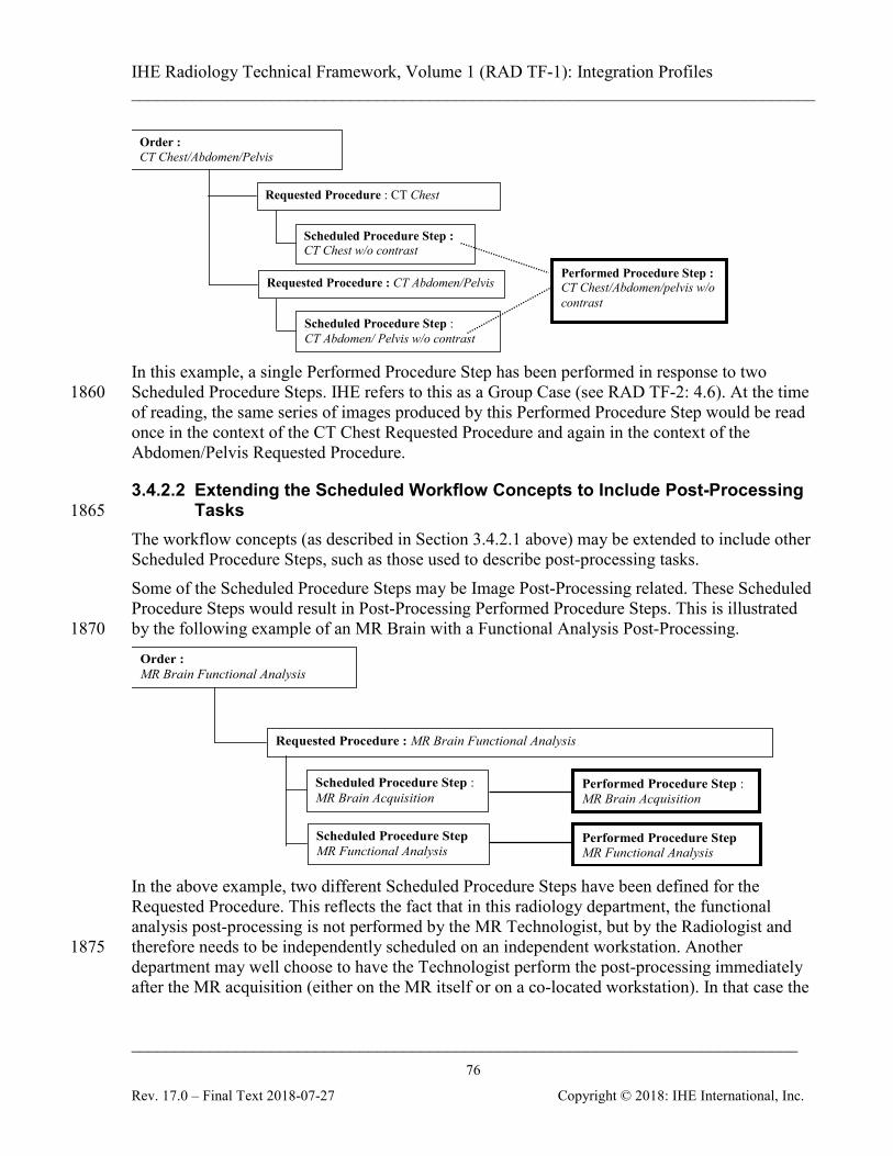
IHE Radiology Technical Framework, Volume 1 (RAD TF-1): Integration Profiles ______________________________________________________________________________
____________________________________________________________________________ 76
Rev. 17.0 – Final Text 2018-07-27 Copyright © 2018: IHE International, Inc.
Requested Procedure : CT Chest
Order : CT Chest/Abdomen/Pelvis
Requested Procedure : CT Abdomen/Pelvis
Scheduled Procedure Step : CT Abdomen/ Pelvis w/o contrast
Scheduled Procedure Step : CT Chest w/o contrast
Performed Procedure Step : CT Chest/Abdomen/pelvis w/o contrast
In this example, a single Performed Procedure Step has been performed in response to two Scheduled Procedure Steps. IHE refers to this as a Group Case (see RAD TF-2: 4.6). At the time 1860 of reading, the same series of images produced by this Performed Procedure Step would be read once in the context of the CT Chest Requested Procedure and again in the context of the Abdomen/Pelvis Requested Procedure.
3.4.2.2 Extending the Scheduled Workflow Concepts to Include Post-Processing Tasks 1865
The workflow concepts (as described in Section 3.4.2.1 above) may be extended to include other Scheduled Procedure Steps, such as those used to describe post-processing tasks. Some of the Scheduled Procedure Steps may be Image Post-Processing related. These Scheduled Procedure Steps would result in Post-Processing Performed Procedure Steps. This is illustrated by the following example of an MR Brain with a Functional Analysis Post-Processing. 1870 Order :
MR Brain Functional Analysis
Requested Procedure : MR Brain Functional Analysis
Scheduled Procedure Step : MR Brain Acquisition
Scheduled Procedure Step MR Functional Analysis
Performed Procedure Step MR Functional Analysis
Performed Procedure Step : MR Brain Acquisition
In the above example, two different Scheduled Procedure Steps have been defined for the Requested Procedure. This reflects the fact that in this radiology department, the functional analysis post-processing is not performed by the MR Technologist, but by the Radiologist and therefore needs to be independently scheduled on an independent workstation. Another 1875 department may well choose to have the Technologist perform the post-processing immediately after the MR acquisition (either on the MR itself or on a co-located workstation). In that case the
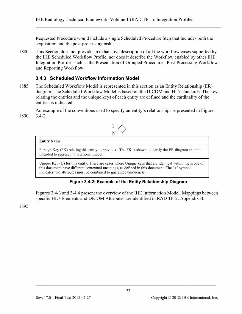
IHE Radiology Technical Framework, Volume 1 (RAD TF-1): Integration Profiles ______________________________________________________________________________
____________________________________________________________________________ 77
Rev. 17.0 – Final Text 2018-07-27 Copyright © 2018: IHE International, Inc.
Requested Procedure would include a single Scheduled Procedure Step that includes both the acquisition and the post-processing task. This Section does not provide an exhaustive description of all the workflow cases supported by 1880 the IHE Scheduled Workflow Profile, nor does it describe the Workflow enabled by other IHE Integration Profiles such as the Presentation of Grouped Procedures, Post-Processing Workflow and Reporting Workflow.
3.4.3 Scheduled Workflow Information Model The Scheduled Workflow Model is represented in this section as an Entity Relationship (ER) 1885 diagram. The Scheduled Workflow Model is based on the DICOM and HL7 standards. The keys relating the entities and the unique keys of each entity are defined and the cardinality of the entities is indicated. An example of the conventions used to specify an entity’s relationships is presented in Figure 3.4-2. 1890
1 N
Entity Name
Foreign Key (FK) relating this entity to previous - The FK is shown to clarify the ER diagram and not intended to represent a relational model. Unique Key (U) for this entity. There are cases where Unique keys that are identical within the scope of this document have different contextual meanings, as defined in this document. The "+" symbol indicates two attributes must be combined to guarantee uniqueness.
Figure 3.4-2: Example of the Entity Relationship Diagram
Figures 3.4-3 and 3-4.4 present the overview of the IHE Information Model. Mappings between specific HL7 Elements and DICOM Attributes are identified in RAD TF-2: Appendix B. 1895
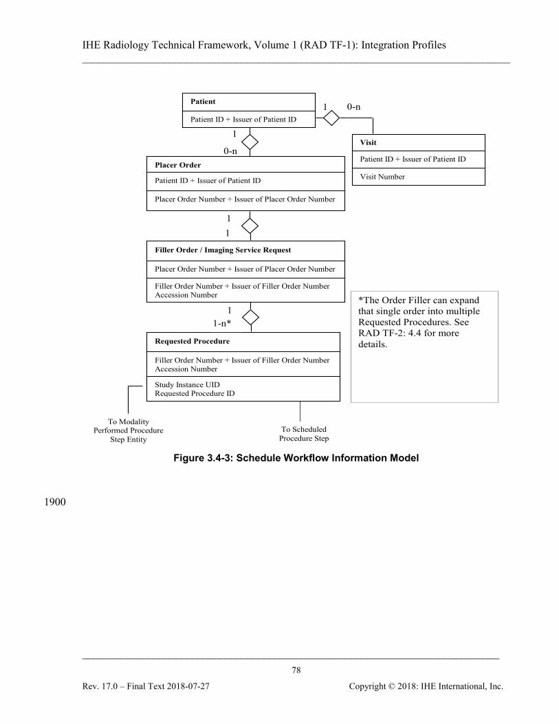
IHE Radiology Technical Framework, Volume 1 (RAD TF-1): Integration Profiles ______________________________________________________________________________
____________________________________________________________________________ 78
Rev. 17.0 – Final Text 2018-07-27 Copyright © 2018: IHE International, Inc.
1
1 1
1
1
0-n
To Scheduled Procedure Step
Patient
Patient ID + Issuer of Patient ID
Visit
Patient ID + Issuer of Patient ID Visit Number
Placer Order
Patient ID + Issuer of Patient ID Placer Order Number + Issuer of Placer Order Number
Filler Order / Imaging Service Request
Placer Order Number + Issuer of Placer Order Number Filler Order Number + Issuer of Filler Order Number Accession Number
Requested Procedure
Filler Order Number + Issuer of Filler Order Number Accession Number Study Instance UID Requested Procedure ID
To Modality Performed Procedure
Step Entity
0-n
1-n*
*The Order Filler can expand that single order into multiple Requested Procedures. See RAD TF-2: 4.4 for more details.
Figure 3.4-3: Schedule Workflow Information Model
1900
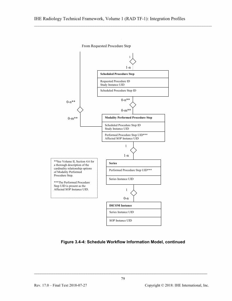
IHE Radiology Technical Framework, Volume 1 (RAD TF-1): Integration Profiles ______________________________________________________________________________
____________________________________________________________________________ 79
Rev. 17.0 – Final Text 2018-07-27 Copyright © 2018: IHE International, Inc.
1
N
Scheduled Procedure Step
Requested Procedure ID Study Instance UID Scheduled Procedure Step ID
Modality Performed Procedure Step
Scheduled Procedure Step ID Study Instance UID Performed Procedure Step UID*** Affected SOP Instance UID
Series
Performed Procedure Step UID*** Series Instance UID
DICOM Instance
Series Instance UID SOP Instance UID
1
1
From Requested Procedure Step
**See Volume II, Section 4.6 for a thorough description of the cardinality relationship options of Modality Performed Procedure Step. ***The Performed Procedure Step UID is present as the Affected SOP Instance UID.
1-n
0-n**
0-m**
0-n**
0-m**
1-n
0-n
1
Figure 3.4-4: Schedule Workflow Information Model, continued
IHE Radiology Technical Framework, Volume 1 (RAD TF-1): Integration Profiles ______________________________________________________________________________
____________________________________________________________________________ 80
Rev. 17.0 – Final Text 2018-07-27 Copyright © 2018: IHE International, Inc.
4 Patient Information Reconciliation (PIR) 1905
The Patient Information Reconciliation Integration Profile extends the Scheduled Workflow and the Reporting Workflow Integration Profile by offering the means to match images, diagnostic reports, and other evidence objects acquired for a misidentified or unidentified patient (for example, during a trauma case) with the patient’s record. In the example of the trauma case, this integration profile allows subsequent reconciliation of the patient record with images that are 1910 acquired (either without a prior registration or under a generic registration) before the patient’s identity can be determined. Thus images can be acquired and interpreted immediately and later, when the patient’s official registration and order information is entered into the ADT, Order Placer and Order Filler Systems, this information is matched with the acquired image set and reports, greatly simplifying these exception handling situations. In addition, this Integration 1915 Profile allows the Image Manager and Report Manager to receive patient update messages to maintain consistency of the patient information. The Image Manager and Report Manager do not receive those transactions in the Scheduled Workflow Integration Profile.
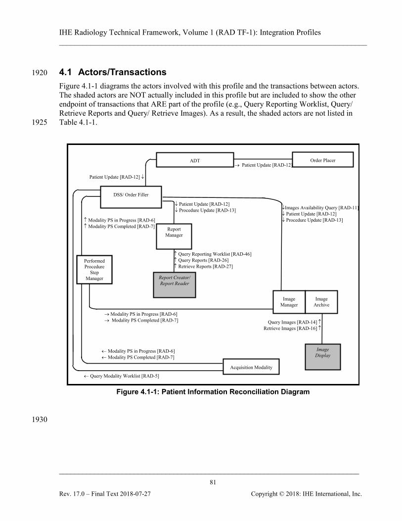
IHE Radiology Technical Framework, Volume 1 (RAD TF-1): Integration Profiles ______________________________________________________________________________
____________________________________________________________________________ 81
Rev. 17.0 – Final Text 2018-07-27 Copyright © 2018: IHE International, Inc.
4.1 Actors/Transactions 1920
Figure 4.1-1 diagrams the actors involved with this profile and the transactions between actors. The shaded actors are NOT actually included in this profile but are included to show the other endpoint of transactions that ARE part of the profile (e.g., Query Reporting Worklist, Query/ Retrieve Reports and Query/ Retrieve Images). As a result, the shaded actors are not listed in Table 4.1-1. 1925
→ Patient Update [RAD-12]
Patient Update [RAD-12] ↓
ADT
↓Images Availability Query [RAD-11] ↓ Patient Update [RAD-12] ↓ Procedure Update [RAD-13]
← Query Modality Worklist [RAD-5]
Acquisition Modality
Image Manager
Image Archive
← Modality PS in Progress [RAD-6] ← Modality PS Completed [RAD-7]
Order Placer
DSS/ Order Filler
Report Manager
↓ Patient Update [RAD-12] ↓ Procedure Update [RAD-13]
Performed Procedure
Step Manager
→ Modality PS in Progress [RAD-6] → Modality PS Completed [RAD-7]
↑ Modality PS in Progress [RAD-6] ↑ Modality PS Completed [RAD-7]
Image Display
Query Images [RAD-14] ↑ Retrieve Images [RAD-16] ↑
Report Creator/ Report Reader
↑ Query Reporting Worklist [RAD-46] ↑ Query Reports [RAD-26] ↑ Retrieve Reports [RAD-27]
Figure 4.1-1: Patient Information Reconciliation Diagram
1930
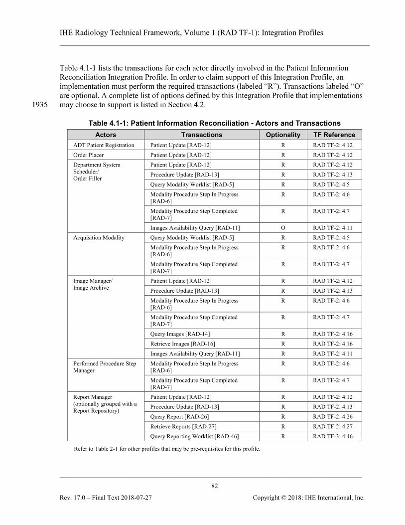
IHE Radiology Technical Framework, Volume 1 (RAD TF-1): Integration Profiles ______________________________________________________________________________
____________________________________________________________________________ 82
Rev. 17.0 – Final Text 2018-07-27 Copyright © 2018: IHE International, Inc.
Table 4.1-1 lists the transactions for each actor directly involved in the Patient Information Reconciliation Integration Profile. In order to claim support of this Integration Profile, an implementation must perform the required transactions (labeled “R”). Transactions labeled “O” are optional. A complete list of options defined by this Integration Profile that implementations may choose to support is listed in Section 4.2. 1935
Table 4.1-1: Patient Information Reconciliation - Actors and Transactions Actors Transactions Optionality TF Reference
ADT Patient Registration Patient Update [RAD-12] R RAD TF-2: 4.12 Order Placer Patient Update [RAD-12] R RAD TF-2: 4.12 Department System Scheduler/ Order Filler
Patient Update [RAD-12] R RAD TF-2: 4.12 Procedure Update [RAD-13] R RAD TF-2: 4.13 Query Modality Worklist [RAD-5] R RAD TF-2: 4.5 Modality Procedure Step In Progress [RAD-6]
R RAD TF-2: 4.6
Modality Procedure Step Completed [RAD-7]
R RAD TF-2: 4.7
Images Availability Query [RAD-11] O RAD TF-2: 4.11 Acquisition Modality Query Modality Worklist [RAD-5] R RAD TF-2: 4.5
Modality Procedure Step In Progress [RAD-6]
R RAD TF-2: 4.6
Modality Procedure Step Completed [RAD-7]
R RAD TF-2: 4.7
Image Manager/ Image Archive
Patient Update [RAD-12] R RAD TF-2: 4.12 Procedure Update [RAD-13] R RAD TF-2: 4.13 Modality Procedure Step In Progress [RAD-6]
R RAD TF-2: 4.6
Modality Procedure Step Completed [RAD-7]
R RAD TF-2: 4.7
Query Images [RAD-14] R RAD TF-2: 4.16 Retrieve Images [RAD-16] R RAD TF-2: 4.16 Images Availability Query [RAD-11] R RAD TF-2: 4.11
Performed Procedure Step Manager
Modality Procedure Step In Progress [RAD-6]
R RAD TF-2: 4.6
Modality Procedure Step Completed [RAD-7]
R RAD TF-2: 4.7
Report Manager (optionally grouped with a Report Repository)
Patient Update [RAD-12] R RAD TF-2: 4.12 Procedure Update [RAD-13] R RAD TF-2: 4.13 Query Report [RAD-26] R RAD TF-2: 4.26 Retrieve Reports [RAD-27] R RAD TF-2: 4.27 Query Reporting Worklist [RAD-46] R RAD TF-3: 4.46
Refer to Table 2-1 for other profiles that may be pre-requisites for this profile.
IHE Radiology Technical Framework, Volume 1 (RAD TF-1): Integration Profiles ______________________________________________________________________________
____________________________________________________________________________ 83
Rev. 17.0 – Final Text 2018-07-27 Copyright © 2018: IHE International, Inc.
Note that this is an enhancing profile. Actors must perform reconciliation for all other profiles they support. Where the actor entry in the table refers to another integration profile (e.g., Scheduled 1940 Workflow), all required transactions in the referenced profile for that actor must be implemented. Some of these transactions in the referenced integration profile (for example the Department System Scheduler responsibilities in the Patient Update transaction) are extended as specified in Volume 2 and Volume 3. To support the Patient Information Reconciliation Profile, an actor that claims support of other 1945 content profiles (Consistent Presentation of Images, Key Image Notes, Simple Image & Numeric Reports or Evidence Documents) is required to support reconciliation of the relevant Evidence Objects. The following diagrams will mostly show the management/ reconciliation of images. The Report Manager must update existing workitems based on the patient information update but since the report content is not modified the rest of the reporting workflow is not affected. In other 1950 words, no additional reporting workitems will be scheduled or cancelled because of this update. The report status is also not affected e.g., a verified report in which the patient information has been updated remains verified. This profile does not require notification of other actors about the patient update. In case of DICOM SR, the patient information might be included in the content sequence. The 1955 update of the patient information in the report header might result in inconsistent header information with the report content. The patient information update shall not create a new SR SOP instance, according to DICOM SR SOP Class behavior as described in DICOM PS3.4, Annex O.
4.2 Patient Information Reconciliation Integration Profile Options 1960
Options that may be selected for this Integration Profile are listed in the Table 4.2-1 along with the actors to which they apply.
Table 4.2-1: Patient Information Reconciliation – Actors and Options Actor Options TF Reference
ADT Patient Registration HL7 v2.5.1 RAD TF-1: 4.2.1 RAD TF-2: 4.12
Order Placer HL7 v2.5.1 RAD TF-1: 4.2.1 RAD TF-2: 4.12
DSS/Order Filler HL7 v2.5.1 RAD TF-1: 4.2.1 RAD TF-2: 4.12 RAD TF-2: 4.13
Acquisition Modality No options defined - Image Manager/ Image Archive HL7 v2.5.1 RAD TF-1: 4.2.1
RAD TF-2: 4.12 RAD TF-2: 4.13
Performed Procedure Step Manager No options defined -
IHE Radiology Technical Framework, Volume 1 (RAD TF-1): Integration Profiles ______________________________________________________________________________
____________________________________________________________________________ 84
Rev. 17.0 – Final Text 2018-07-27 Copyright © 2018: IHE International, Inc.
Actor Options TF Reference Report Manager HL7 v2.5.1 RAD TF-1: 4.2.1
RAD TF-2: 4.12 RAD TF-2: 4.13
4.2.1 HL7 v2.5.1 Option The HL7 v2.5.1 Option requires actors to support HL7 v2.5.1 in addition to HL7 v2.3.1 in the 1965 transactions referenced in Table 4.2-1. The actor shall permit configuration for each system that it communicates with using the referenced transactions whether HL7 v2.3.1 or HL7 v2.5.1 is used. It is possible that the actor may receive HL7 v2.3.1 messages and send HL7 v2.5.1 messages or vice versa. The specifications in the HL7 v2.5.1 Option maintain semantic equivalency with HL7 v2.3.1 1970 implementations and the field correspondences are summarized in RAD TF-2: Appendix E.
4.3 Unidentified Patient Image Acquisition and Reconciliation This section describes the general process flow related to the handling of procedures for unidentified patients. The transactions covered are Patient Registration [RAD-1], Placer Order Management [RAD-2], Procedure Scheduled [RAD-4], MWL Provided [RAD-5], Modality 1975 Procedure Step In Progress [RAD-6], Modality Procedure Step Completed/Discontinued [RAD-7], Patient Update [RAD-12], and Procedure Update [RAD-13]. The Unidentified Patient case covers the trauma case or emergency room patient when a patient’s condition requires that a procedure be conducted immediately. This is done before proper patient registration, ordering and/or scheduling of the procedure are performed (due to the 1980 lack of either information or time or other deviation from the normal process flow). In this case patient/study information must be later reconciled and properly updated at the ADT, Order Placer, Department System Scheduler/Order Filler, Image Manager and Report Manager. There are several examples of information flow in this case. These examples are described in use cases (see Sections 4.4.1 – 4.4.5 for details): 1985
• Case 1: Unidentified Patient registered at ADT and ordered at Order Placer.
• Case 2: Unidentified Patient registered at ADT and ordered at Department System Scheduler/Order Filler.
• Case 3: Unidentified Patient registered at ADT but acquisition completed at Modality prior to order. 1990
In cases 1, 2, and 3, the ADT may utilize the Master Patient Index (MPI) internally. The interaction of the ADT with MPI to resolve the patient information to the correct Patient ID may be embedded in the process of patient information reconciliation within the ADT role. The IHE Technical Framework in future years may define patient reconciliation transactions using MPI. The Radiology Technical Framework also supports cases when registration or temporary 1995 registration of a patient by ADT is not applicable or desired, for example:
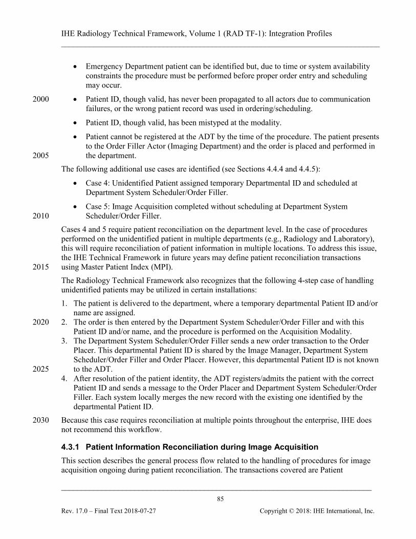
IHE Radiology Technical Framework, Volume 1 (RAD TF-1): Integration Profiles ______________________________________________________________________________
____________________________________________________________________________ 85
Rev. 17.0 – Final Text 2018-07-27 Copyright © 2018: IHE International, Inc.
• Emergency Department patient can be identified but, due to time or system availability constraints the procedure must be performed before proper order entry and scheduling may occur.
• Patient ID, though valid, has never been propagated to all actors due to communication 2000 failures, or the wrong patient record was used in ordering/scheduling.
• Patient ID, though valid, has been mistyped at the modality.
• Patient cannot be registered at the ADT by the time of the procedure. The patient presents to the Order Filler Actor (Imaging Department) and the order is placed and performed in the department. 2005
The following additional use cases are identified (see Sections 4.4.4 and 4.4.5):
• Case 4: Unidentified Patient assigned temporary Departmental ID and scheduled at Department System Scheduler/Order Filler.
• Case 5: Image Acquisition completed without scheduling at Department System Scheduler/Order Filler. 2010
Cases 4 and 5 require patient reconciliation on the department level. In the case of procedures performed on the unidentified patient in multiple departments (e.g., Radiology and Laboratory), this will require reconciliation of patient information in multiple locations. To address this issue, the IHE Technical Framework in future years may define patient reconciliation transactions using Master Patient Index (MPI). 2015 The Radiology Technical Framework also recognizes that the following 4-step case of handling unidentified patients may be utilized in certain installations: 1. The patient is delivered to the department, where a temporary departmental Patient ID and/or
name are assigned. 2. The order is then entered by the Department System Scheduler/Order Filler and with this 2020
Patient ID and/or name, and the procedure is performed on the Acquisition Modality. 3. The Department System Scheduler/Order Filler sends a new order transaction to the Order
Placer. This departmental Patient ID is shared by the Image Manager, Department System Scheduler/Order Filler and Order Placer. However, this departmental Patient ID is not known to the ADT. 2025
4. After resolution of the patient identity, the ADT registers/admits the patient with the correct Patient ID and sends a message to the Order Placer and Department System Scheduler/Order Filler. Each system locally merges the new record with the existing one identified by the departmental Patient ID.
Because this case requires reconciliation at multiple points throughout the enterprise, IHE does 2030 not recommend this workflow.
4.3.1 Patient Information Reconciliation during Image Acquisition This section describes the general process flow related to the handling of procedures for image acquisition ongoing during patient reconciliation. The transactions covered are Patient
IHE Radiology Technical Framework, Volume 1 (RAD TF-1): Integration Profiles ______________________________________________________________________________
____________________________________________________________________________ 86
Rev. 17.0 – Final Text 2018-07-27 Copyright © 2018: IHE International, Inc.
Registration [RAD-1], Placer Order Management [RAD-2], Procedure Scheduled [RAD-4], 2035 MWL Provided [RAD-5], Modality Procedure Step In Progress [RAD-6], Modality Procedure Step Completed/Discontinued [RAD-7], Patient Update [RAD-12], Procedure Update [RAD-13], Query Images [RAD-14], Query Presentation States [RAD-15], Retrieve Images [RAD-16] and Retrieve Presentation States [RAD-17]. When a Patient Update occurs, in addition to the information exchange between the ADT, Order 2040 Placer and Department System Scheduler/Order Filler, Patient Update information is also sent to the Image Manager. Even after a Patient Update has occurred images coming from the Modality may continue to use the original Patient Information, so on-going Patient update with incoming images from the modality may be necessary. It is the responsibility of the Image Manager to ensure that the patient information is updated in the images, Grayscale Softcopy Presentation 2045 States and other Evidence Objects when they are retrieved from the Image Archive. This example is described in use case 6 (see Section 4.4.6).
4.4 Use Cases The following sections describe the Unidentified Patient use cases. For the purpose of simplification, the following transactions were omitted from the corresponding diagrams: 2050
• Modality Performed Procedure Step In Progress [RAD-6]
• Modality Images Stored [RAD-8]
• Modality Presentation State Stored [RAD-9]
• Storage Commitment [RAD-10]
These transactions may occur within the time frame of the diagram, but their content does not 2055 affect each of the use cases.
4.4.1 Case 1: Unidentified Patient Registered at ADT and Ordered at the Order Placer
The ADT is a single point of patient reconciliation in the enterprise. Process flow requires that any unidentified patient be assigned a permanent Patient ID and a temporary name (e.g., “John 2060 Doe”). All subsequent transactions follow the normal flow (see Section 3.1) including order entry and procedure scheduling. When the real patient identity is known, the ADT is responsible for reconciliation of its own records as well as informing the Order Placer and Department System Scheduler/Order Filler about corresponding changes. The ADT sends a Patient Update message to both the Order Placer and Department System Scheduler/Order Filler. The 2065 Department System Scheduler/Order Filler sends the Patient Update message to the Image Manager and the Report Manager.
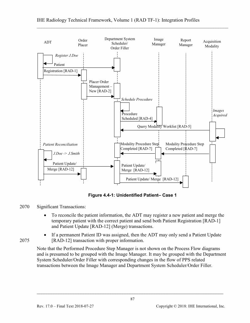
IHE Radiology Technical Framework, Volume 1 (RAD TF-1): Integration Profiles ______________________________________________________________________________
____________________________________________________________________________ 87
Rev. 17.0 – Final Text 2018-07-27 Copyright © 2018: IHE International, Inc.
Query Modality Worklist [RAD-5]
ADT Order Placer
Register J.Doe
Image Manager
Acquisition Modality
Placer Order Management – New [RAD-2]
Patient Reconciliation
Department System Scheduler/ Order Filler
Schedule Procedure
Procedure Scheduled [RAD-4]
J.Doe -> J.Smith
Patient Update/ Merge [RAD-12]
Images Acquired
Modality Procedure Step Completed [RAD-7]
Patient Registration [RAD-1]
Patient Update/ Merge [RAD-12]
Report Manager
Patient Update/ Merge [RAD-12]
Modality Procedure Step Completed [RAD-7]
Figure 4.4-1: Unidentified Patient– Case 1
Significant Transactions: 2070
• To reconcile the patient information, the ADT may register a new patient and merge the temporary patient with the correct patient and send both Patient Registration [RAD-1] and Patient Update [RAD-12] (Merge) transactions.
• If a permanent Patient ID was assigned, then the ADT may only send a Patient Update [RAD-12] transaction with proper information. 2075
Note that the Performed Procedure Step Manager is not shown on the Process Flow diagrams and is presumed to be grouped with the Image Manager. It may be grouped with the Department System Scheduler/Order Filler with corresponding changes in the flow of PPS related transactions between the Image Manager and Department System Scheduler/Order Filler.
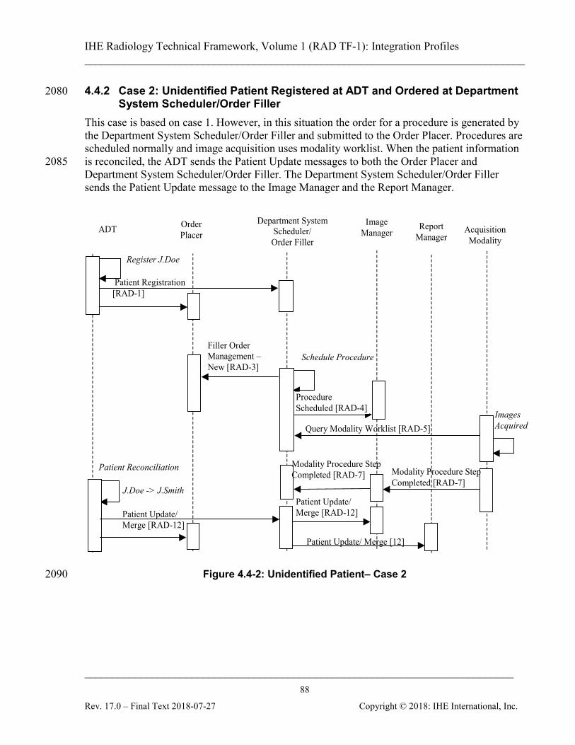
IHE Radiology Technical Framework, Volume 1 (RAD TF-1): Integration Profiles ______________________________________________________________________________
____________________________________________________________________________ 88
Rev. 17.0 – Final Text 2018-07-27 Copyright © 2018: IHE International, Inc.
4.4.2 Case 2: Unidentified Patient Registered at ADT and Ordered at Department 2080 System Scheduler/Order Filler
This case is based on case 1. However, in this situation the order for a procedure is generated by the Department System Scheduler/Order Filler and submitted to the Order Placer. Procedures are scheduled normally and image acquisition uses modality worklist. When the patient information is reconciled, the ADT sends the Patient Update messages to both the Order Placer and 2085 Department System Scheduler/Order Filler. The Department System Scheduler/Order Filler sends the Patient Update message to the Image Manager and the Report Manager.
Patient Update/ Merge [RAD-12]
Patient Registration [RAD-1]
Register J.Doe
Query Modality Worklist [RAD-5]
ADT Order Placer
Image Manager Acquisition
Modality
Filler Order Management – New [RAD-3]
Patient Reconciliation
Department System Scheduler/ Order Filler
Schedule Procedure
Procedure Scheduled [RAD-4]
J.Doe -> J.Smith
Images Acquired
Modality Procedure Step Completed [RAD-7]
Report Manager
Patient Update/ Merge [RAD-12]
Patient Update/ Merge [12]
Modality Procedure Step Completed [RAD-7]
Figure 4.4-2: Unidentified Patient– Case 2 2090
IHE Radiology Technical Framework, Volume 1 (RAD TF-1): Integration Profiles ______________________________________________________________________________
____________________________________________________________________________ 89
Rev. 17.0 – Final Text 2018-07-27 Copyright © 2018: IHE International, Inc.
Significant Transactions:
• To reconcile the patient information, the ADT may register a new patient and merge the temporary patient with the correct patient and send both registration and merge transactions. 2095
• If a permanent Patient ID was assigned, then the ADT may only send a Patient Update transaction with proper information.
• A Filler Order Management (New Order) [RAD-3] transaction is sent from Department System Scheduler/Order Filler to the Order Placer.
4.4.3 Case 3: Unidentified Patient Registered at ADT but Completed at Modality 2100 Prior to Order
As in cases 1 and 2, this uses a permanent Patient ID generated by the ADT. However, no order entry or scheduling takes place before the Acquisition Modality performs the procedure. A permanent Patient ID and a temporary name are manually entered at the Acquisition Modality (typically, from a card) and conveyed to the Department System Scheduler/Order Filler and the 2105 Image Manager by the Acquisition Modality. Subsequently, the Department System Scheduler/Order Filler generates and submits an order to the Order Placer. When the patient information is reconciled, the ADT sends the Patient Update messages to both the Order Placer and the Department System Scheduler/Order Filler. The Department System Scheduler/Order Filler sends a Patient Update message to the Image Manager and the Report Manager. 2110
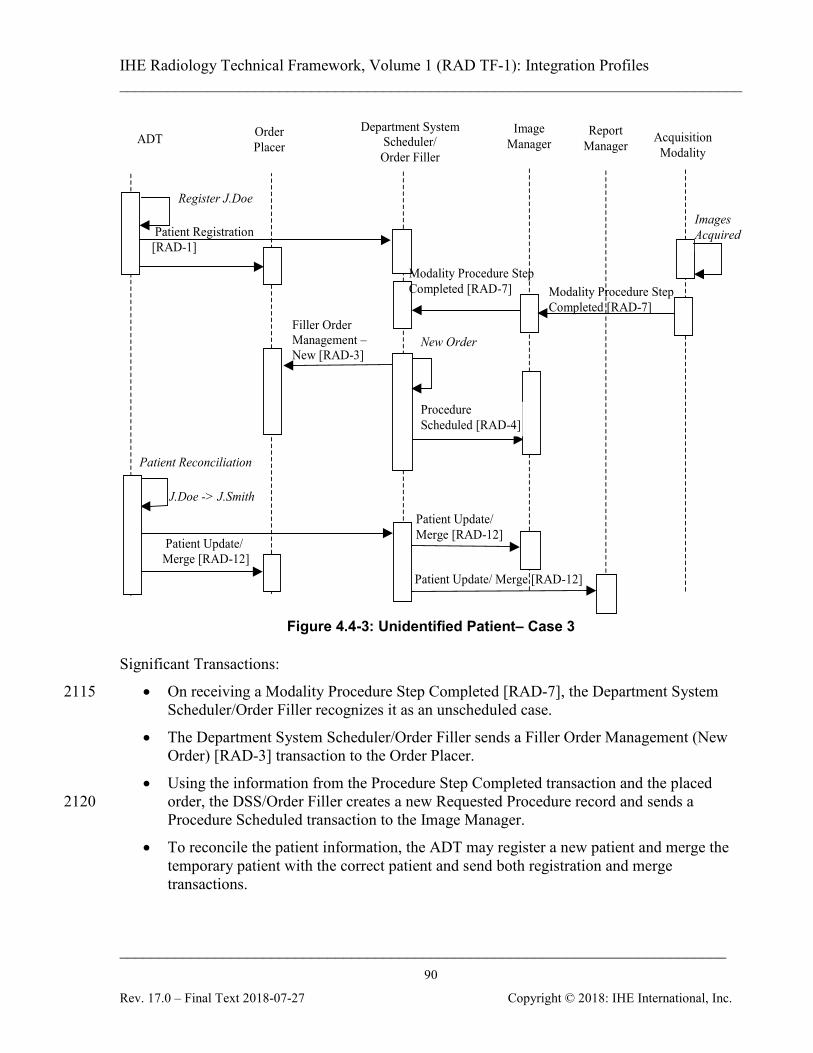
IHE Radiology Technical Framework, Volume 1 (RAD TF-1): Integration Profiles ______________________________________________________________________________
____________________________________________________________________________ 90
Rev. 17.0 – Final Text 2018-07-27 Copyright © 2018: IHE International, Inc.
Patient Update/ Merge [RAD-12]
Patient Registration [RAD-1]
Register J.Doe
ADT Order Placer
Image Manager Acquisition
Modality
Filler Order Management – New [RAD-3]
Patient Reconciliation
Department System Scheduler/ Order Filler
Procedure Scheduled [RAD-4]
J.Doe -> J.Smith
Patient Update/ Merge [RAD-12]
New Order
Images Acquired
Modality Procedure Step Completed [RAD-7]
Report Manager
Patient Update/ Merge [RAD-12]
Modality Procedure Step Completed [RAD-7]
Figure 4.4-3: Unidentified Patient– Case 3
Significant Transactions:
• On receiving a Modality Procedure Step Completed [RAD-7], the Department System 2115 Scheduler/Order Filler recognizes it as an unscheduled case.
• The Department System Scheduler/Order Filler sends a Filler Order Management (New Order) [RAD-3] transaction to the Order Placer.
• Using the information from the Procedure Step Completed transaction and the placed order, the DSS/Order Filler creates a new Requested Procedure record and sends a 2120 Procedure Scheduled transaction to the Image Manager.
• To reconcile the patient information, the ADT may register a new patient and merge the temporary patient with the correct patient and send both registration and merge transactions.
IHE Radiology Technical Framework, Volume 1 (RAD TF-1): Integration Profiles ______________________________________________________________________________
____________________________________________________________________________ 91
Rev. 17.0 – Final Text 2018-07-27 Copyright © 2018: IHE International, Inc.
• If a permanent Patient ID was assigned, then the ADT may only send a Patient Update 2125 transaction with proper information.
• The DSS/Order Filler sends a Patient Update transaction to the Image Manager.
4.4.4 Case 4: Unidentified Patient Assigned Temporary Departmental ID and Scheduled at DSS/Order Filler
In this case, no valid Patient ID is available to the Department System Scheduler/Order Filler. It 2130 assigns a temporary Patient ID and a temporary name and schedules the required procedure.
Note: The Department System Scheduler/Order Filler must ensure that the assigned temporary Patient ID is unique within its scope.
The temporary Patient ID is conveyed to the Image Manager. When patient information becomes known, the ADT sends new patient information to both the Order Placer and the Department 2135 System Scheduler/Order Filler. The Department System Scheduler/Order Filler reconciles received patient information with that associated with the temporary Patient ID and merges the permanent patient record with its own temporary one and sends a Patient Update transaction to the Image Manager and the Report Manager. At the same time, the Department System Scheduler/Order Filler generates and submits an order to the Order Placer using a permanent 2140 Patient ID.

IHE Radiology Technical Framework, Volume 1 (RAD TF-1): Integration Profiles ______________________________________________________________________________
____________________________________________________________________________ 92
Rev. 17.0 – Final Text 2018-07-27 Copyright © 2018: IHE International, Inc.
Patient Registration [RAD-1]
Register J.Smith
Query Modality Worklist [RAD-5]
ADT Order Placer
Image Manager Acquisition
Modality
Filler Order Management - New [RAD-3]
Department System Scheduler/
Order Filler
Schedule Procedure
Procedure Scheduled [RAD-4]
Patient Update/ Merge [RAD-12]
Patient Reconciliation
Images Acquired
Modality Procedure Step Completed [RAD-7]
Procedure Update [RAD-13]
Report Manager
Patient Update/ Merge [RAD-12]
Modality Procedure Step Completed [RAD-7]
Figure 4.4-4: Unidentified Patient– Case 4
Significant Transactions:
• Patient information is reconciled internally by the Department System Scheduler/Order 2145 Filler using the Patient Registration from ADT.
• The Department System Scheduler/Order Filler sends the Patient Update [RAD-12] transaction to the Image Manager.
• The Department System Scheduler/Order Filler sends the Filler Order Management (New Order) [RAD-3] transaction to the Order Placer. 2150
4.4.5 Case 5: Image Acquisition Completed Without Scheduling at Department System Scheduler/Order Filler
In this case, no valid Patient ID is available to the Department System Scheduler/Order Filler and no scheduling is done before the procedure is performed. A temporary ID and name are entered
IHE Radiology Technical Framework, Volume 1 (RAD TF-1): Integration Profiles ______________________________________________________________________________
____________________________________________________________________________ 93
Rev. 17.0 – Final Text 2018-07-27 Copyright © 2018: IHE International, Inc.
by the technologist at the Modality and conveyed to the Department System Scheduler/Order 2155 Filler and to the Image Manager. The Patient ID and name are selected by the technologist according to the locally defined rules; for example, selected from the predefined pool of “Patient ID–patient name” pairs. The rules for selecting temporary Patient ID shall guarantee its uniqueness within the scope of Department System Scheduler/Order Filler. Upon receiving the Modality Procedure Step Completed message, the DSS/Order Filler and 2160 Image Manager recognize an unscheduled case based on the content of the message (absent or empty Referenced Study Sequence, see RAD TF-2: Appendix A). When patient information becomes known, the ADT sends the new patient information to both the Order Placer and Department System Scheduler/Order Filler. The Department System Scheduler/Order Filler performs a merge of the permanent patient record with the temporary one and sends a Patient 2165 Update to the Image Manager and the Report Manager. At the same time, Department System Scheduler/Order Filler generates and submits an order to the Order Placer using a valid Patient ID.
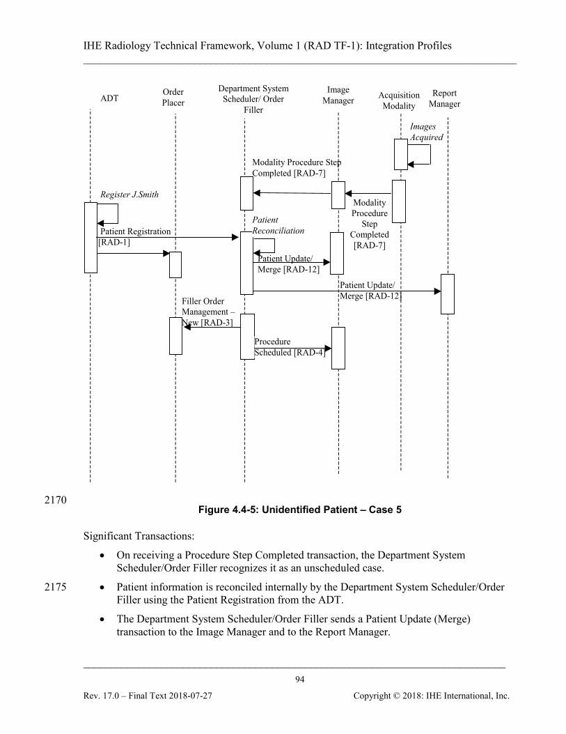
IHE Radiology Technical Framework, Volume 1 (RAD TF-1): Integration Profiles ______________________________________________________________________________
____________________________________________________________________________ 94
Rev. 17.0 – Final Text 2018-07-27 Copyright © 2018: IHE International, Inc.
Patient Registration [RAD-1]
Register J.Smith
ADT Order Placer
Image Manager Acquisition
Modality
Filler Order Management – New [RAD-3]
Department System Scheduler/ Order
Filler
Patient Update/ Merge [RAD-12]
Procedure Scheduled [RAD-4]
Patient Reconciliation
Images Acquired
Modality Procedure Step Completed [RAD-7]
Modality Procedure
Step Completed [RAD-7]
Report Manager
Patient Update/ Merge [RAD-12]
2170 Figure 4.4-5: Unidentified Patient – Case 5
Significant Transactions:
• On receiving a Procedure Step Completed transaction, the Department System Scheduler/Order Filler recognizes it as an unscheduled case.
• Patient information is reconciled internally by the Department System Scheduler/Order 2175 Filler using the Patient Registration from the ADT.
• The Department System Scheduler/Order Filler sends a Patient Update (Merge) transaction to the Image Manager and to the Report Manager.
IHE Radiology Technical Framework, Volume 1 (RAD TF-1): Integration Profiles ______________________________________________________________________________
____________________________________________________________________________ 95
Rev. 17.0 – Final Text 2018-07-27 Copyright © 2018: IHE International, Inc.
• The Department System Scheduler/Order Filler sends a Filler Order Management (New Order) [RAD-3] transaction to the Order Placer. 2180
• Using the information from the Procedure Step Completed transaction and placed order, the Department System Scheduler/Order Filler creates a new Requested Procedure record and sends a Procedure Scheduled [RAD-4] transaction to the Image Manager and Report Manager.
4.4.6 Case 6: Patient Information Reconciliation During Image Acquisition 2185 Updates may need to occur after the initial Patient Registration and Order Placement has occurred. The Modality may have requested information from the Department System Scheduler before the update has occurred and continue to send the images with the original Patient Registration and Order information. The Image Manager will need to continue updating the patient information from items retrieved from the Image Archive. 2190 Significant Transactions:
• The Modality may continue to send information using the original patient information even after the patient update has occurred.
• The Image Manager must continue reconciling Patient Information even after the Patient Update transaction has been completed. 2195
Only partial transactions are shown. Other transactions are performed according to the profile requirements.
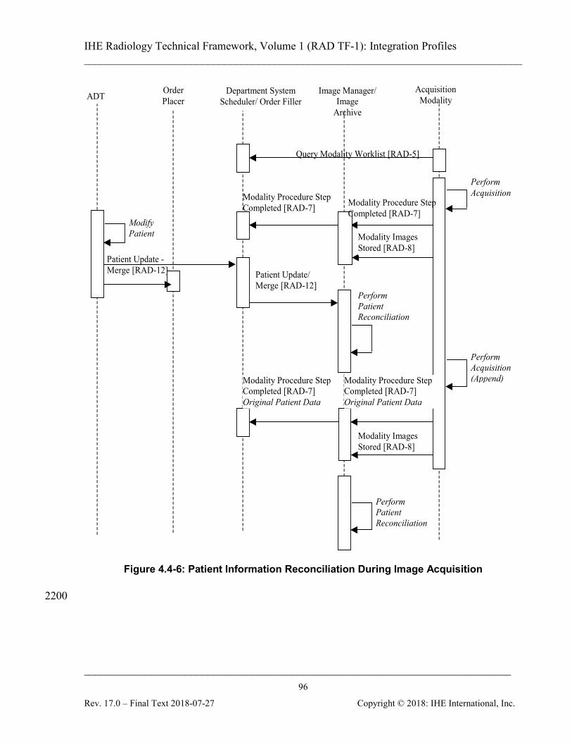
IHE Radiology Technical Framework, Volume 1 (RAD TF-1): Integration Profiles ______________________________________________________________________________
____________________________________________________________________________ 96
Rev. 17.0 – Final Text 2018-07-27 Copyright © 2018: IHE International, Inc.
Query Modality Worklist [RAD-5]
ADT Order Placer
Image Manager/ Image
Archive
Acquisition Modality
Department System Scheduler/ Order Filler
Patient Update - Merge [RAD-12]
Modify Patient
Perform Acquisition
Modality Images Stored [RAD-8]
Perform Acquisition (Append)
Modality Images Stored [RAD-8]
Modality Procedure Step Completed [RAD-7]
Modality Procedure Step Completed [RAD-7] Original Patient Data
Patient Update/ Merge [RAD-12]
Perform Patient Reconciliation
Perform Patient Reconciliation
Modality Procedure Step Completed [RAD-7]
Modality Procedure Step Completed [RAD-7] Original Patient Data
Figure 4.4-6: Patient Information Reconciliation During Image Acquisition
2200
IHE Radiology Technical Framework, Volume 1 (RAD TF-1): Integration Profiles ______________________________________________________________________________
____________________________________________________________________________ 97
Rev. 17.0 – Final Text 2018-07-27 Copyright © 2018: IHE International, Inc.
5 Consistent Presentation of Images (CPI) The Consistent Presentation of Images Integration Profile specifies a number of transactions that maintain the consistency of presentation for grayscale images. The presentation of images depends upon the contrast/brightness and the spatial and graphical operations applied, such as 2205 user annotations, shutters, flip/rotate, display area selection, and zoom. The spatial and graphical operations are defined in the Grayscale Softcopy Presentation State. For the consistency of the perceived pixel intensity a standard contrast curve, the Grayscale Standard Display Function, has been defined against which different types of display and hardcopy output devices are calibrated. This profile is intended to establish consistency between any combination of softcopy and 2210 hardcopy displays. In order to guarantee both grayscale contrast/brightness consistency and spatial/ graphical consistency in presentation of images it is required that both the Grayscale Standard Display Function and the Grayscale Softcopy Presentation State are supported. Note that this Integration Profiles applies only to grayscale images, and is not applicable for color images. 2215 The Scheduled Workflow Profile or Post-Processing Profile, when combined with this profile, allows the process of creating, storing and accessing Presentation States to be managed using worklist to provide the relevant patient and procedure details; and using performed procedure steps to provide status information.
5.1 Actors/Transactions 2220
Figure 5.1-1 diagrams the actors involved with this profile and the transactions between actors.
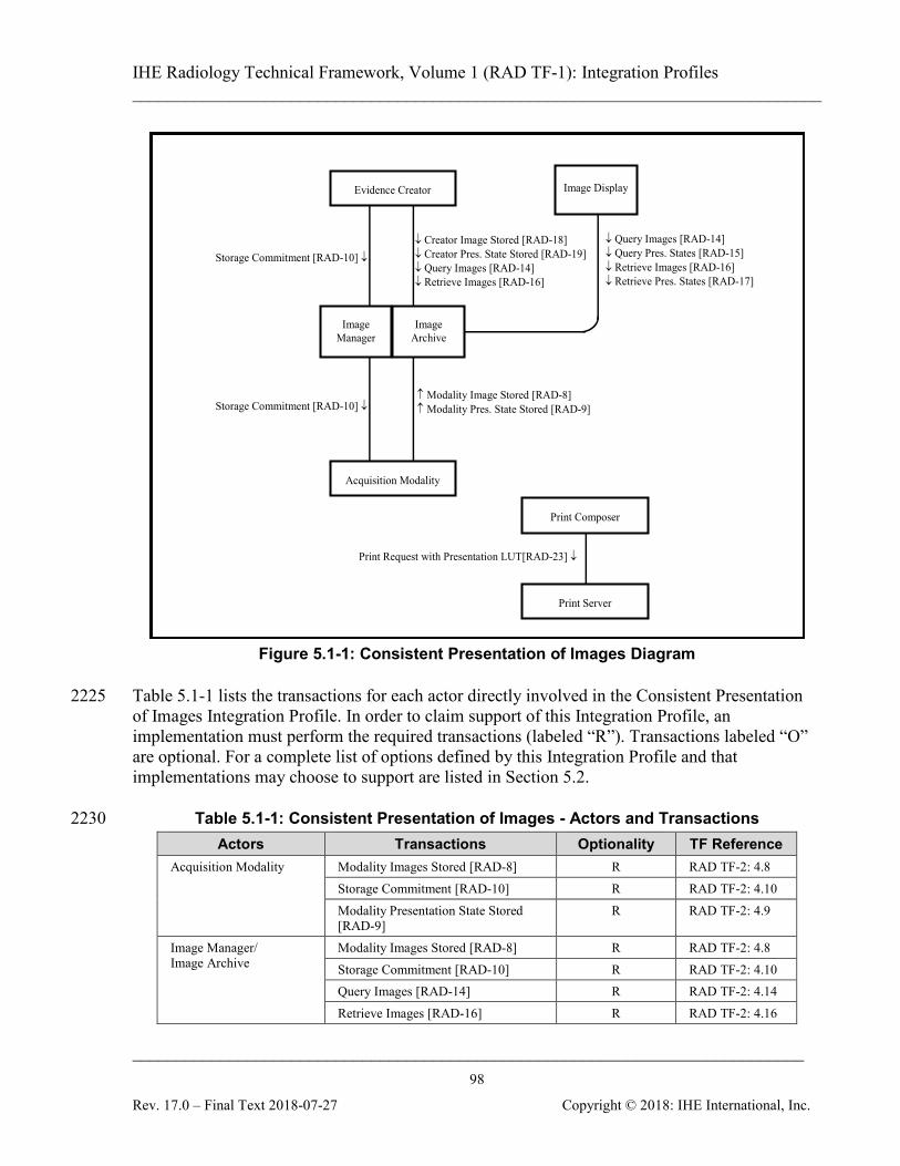
IHE Radiology Technical Framework, Volume 1 (RAD TF-1): Integration Profiles ______________________________________________________________________________
____________________________________________________________________________ 98
Rev. 17.0 – Final Text 2018-07-27 Copyright © 2018: IHE International, Inc.
↓ Query Images [RAD-14] ↓ Query Pres. States [RAD-15] ↓ Retrieve Images [RAD-16] ↓ Retrieve Pres. States [RAD-17]
Image Display
Storage Commitment [RAD-10] ↓
↑ Modality Image Stored [RAD-8] ↑ Modality Pres. State Stored [RAD-9]
↓ Creator Image Stored [RAD-18] ↓ Creator Pres. State Stored [RAD-19] ↓ Query Images [RAD-14] ↓ Retrieve Images [RAD-16]
Evidence Creator
Acquisition Modality
Image Manager
Image Archive
Print Request with Presentation LUT[RAD-23] ↓
Print Server
Print Composer
Storage Commitment [RAD-10] ↓
Figure 5.1-1: Consistent Presentation of Images Diagram
Table 5.1-1 lists the transactions for each actor directly involved in the Consistent Presentation 2225 of Images Integration Profile. In order to claim support of this Integration Profile, an implementation must perform the required transactions (labeled “R”). Transactions labeled “O” are optional. For a complete list of options defined by this Integration Profile and that implementations may choose to support are listed in Section 5.2.
Table 5.1-1: Consistent Presentation of Images - Actors and Transactions 2230 Actors Transactions Optionality TF Reference
Acquisition Modality Modality Images Stored [RAD-8] R RAD TF-2: 4.8 Storage Commitment [RAD-10] R RAD TF-2: 4.10 Modality Presentation State Stored [RAD-9]
R RAD TF-2: 4.9
Image Manager/ Image Archive
Modality Images Stored [RAD-8] R RAD TF-2: 4.8 Storage Commitment [RAD-10] R RAD TF-2: 4.10 Query Images [RAD-14] R RAD TF-2: 4.14 Retrieve Images [RAD-16] R RAD TF-2: 4.16

IHE Radiology Technical Framework, Volume 1 (RAD TF-1): Integration Profiles ______________________________________________________________________________
____________________________________________________________________________ 99
Rev. 17.0 – Final Text 2018-07-27 Copyright © 2018: IHE International, Inc.
Actors Transactions Optionality TF Reference Creator Images Stored [RAD-18] R RAD TF-2: 4.18 Modality Presentation State Stored [RAD-9]
R RAD TF-2: 4.9
Query Presentation States [RAD-15] R RAD TF-2: 4.15 Retrieve Presentation States [RAD-17]
R RAD TF-2: 4.17
Creator Presentation State Stored [RAD-19]
R RAD TF-2: 4.19
Image Display Query Images [RAD-14] R RAD TF-2: 4.14 Retrieve Images [RAD-16] R RAD TF-2: 4.16 Query Presentation States [RAD-15] R RAD TF-2: 4.15 Retrieve Presentation States [RAD-17]
R RAD TF-2: 4.17
Evidence Creator Creator Images Stored [RAD-18] O RAD TF-2: 4.18 Creator Presentation State Stored
[RAD-19] R RAD TF-2: 4.19
Storage Commitment [RAD-10] R RAD TF-2: 4.10 Query Images [RAD-14] O RAD TF-2: 4.14 Retrieve Images [RAD-16] O RAD TF-2: 4.16 Print Composer Print Request with Presentation LUT
[RAD-23] R RAD TF-2: 4.23
Print Server Print Request with Presentation LUT [RAD-23]
R RAD TF-2: 4.23
Note: Refer to Table 2-1 for other profiles that may be pre-requisites for this profile.
5.2 Consistent Presentation of Images Integration Profile Options Options that may be selected for this Integration Profile are listed in the Table 5.2-1 along with the Actors to which they apply. Dependencies between options when applicable are specified in notes. 2235
Table 5.2-1: Consistent Presentation of Images – Actors and Options Actor Options TF Reference
Acquisition Modality No options defined - Image Manager/ Image Archive No options defined - Image Display No options defined - Evidence Creator No options defined - Print Composer User Specifiable Lighting Condition RAD TF-2: 4.23.4.2.4 Print Server No options defined -
IHE Radiology Technical Framework, Volume 1 (RAD TF-1): Integration Profiles ______________________________________________________________________________
____________________________________________________________________________ 100
Rev. 17.0 – Final Text 2018-07-27 Copyright © 2018: IHE International, Inc.
5.3 Consistent Presentation of Images Process Flow This section describes the typical process flow related to viewing images with Grayscale Softcopy Presentation States and performing image post-processing that may generate new images and/or Grayscale Softcopy Presentation States. The transactions covered are [RAD-14] 2240 through [RAD-22]. Consistent Presentation of Images is an integration feature that provides access to images with their full-fidelity content as they were acquired or created. Such access is available either:
• Internally to the source imaging department;
• Between imaging departments (e.g., Cardiology and Radiology); or 2245
• Throughout the Healthcare Enterprise to other departments or care providers other than an imaging department (e.g., Surgery, Neurology, Oncology).
Consistent Presentation of Images enables advanced review as well as simple or sophisticated post-processing of images along with related objects (such as Grayscale Softcopy Presentation States, or Structured Reports) in a variety of clinical scenarios. Examples include the following: 2250
• Based on patient identifying information, a clinician wishes to look for imaging studies performed on this patient. The clinician may access one or more series of images, related to a recent examination;
• A reading physician performing a primary or secondary read wishes to retain viewing parameters including clinical annotations; 2255
• A clinician reviewing a report that references key images wishes to review those images;
• A technologist about to perform an imaging examination wishes to retrieve a prior imaging examination to ensure consistent patient positioning;
• A reading physician interpreting a study wishes to perform a comparison with images acquired in a prior study. The physician also needs to review the images as they were 2260 presented when a prior diagnosis was prepared; and
• A surgeon creates a 3D volume analysis of an image set to plan surgery on a patient. The appearance of grayscale images displayed on different types of softcopy display devices or printed by different types of hardcopy output devices has often been inconsistent. To address this problem and achieve consistent presentation of grayscale images the DICOM Standard defines: 2265
• A standard curve, the Grayscale Standard Display Function, against which different types of display and hardcopy output devices should be calibrated;
• Basic Print Management with Presentation Look Up Table, for controlling the consistent appearance of preformatted images on printed output;
• Grayscale Softcopy Presentation State, an object for storing and communicating the 2270 parameters that describe how an image or set of images shall be displayed. A Grayscale Softcopy Presentation State object contains references to the images it applies to, and the
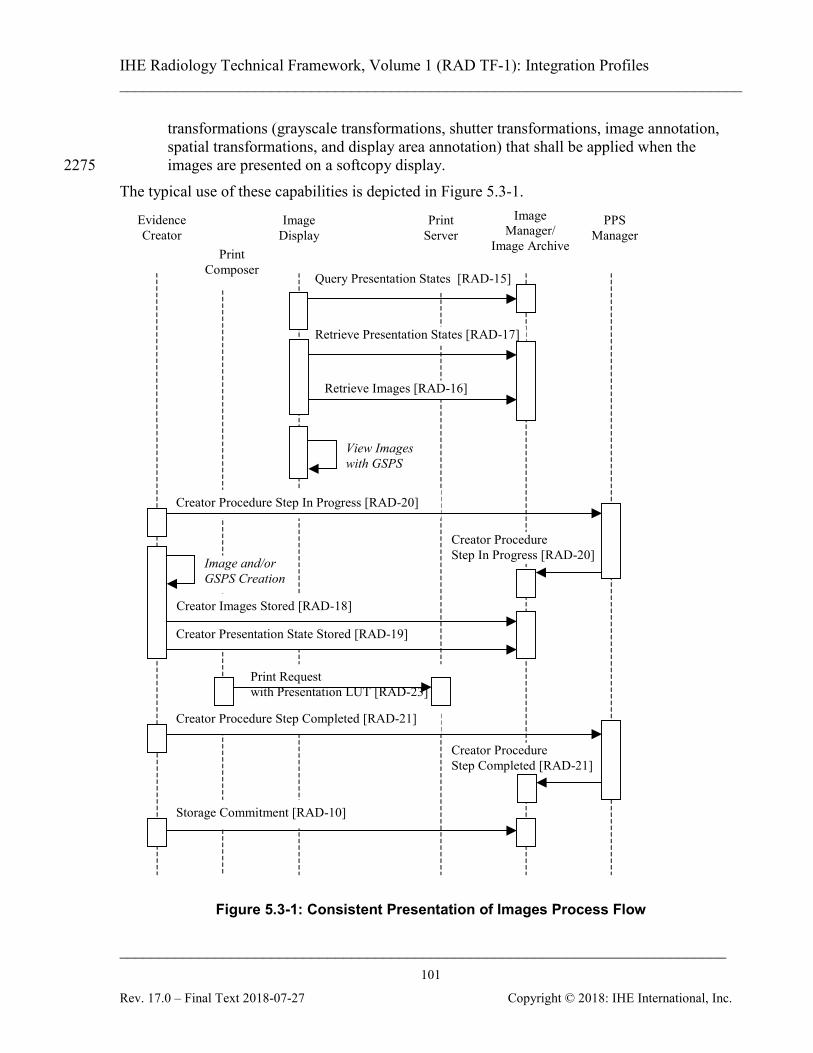
IHE Radiology Technical Framework, Volume 1 (RAD TF-1): Integration Profiles ______________________________________________________________________________
____________________________________________________________________________ 101
Rev. 17.0 – Final Text 2018-07-27 Copyright © 2018: IHE International, Inc.
transformations (grayscale transformations, shutter transformations, image annotation, spatial transformations, and display area annotation) that shall be applied when the images are presented on a softcopy display. 2275
The typical use of these capabilities is depicted in Figure 5.3-1.
Creator Procedure Step In Progress [RAD-20]
Print Composer
Creator Procedure Step Completed [RAD-21]
Creator Presentation State Stored [RAD-19]
Creator Procedure Step In Progress [RAD-20]
Creator Images Stored [RAD-18]
Evidence Creator
Image Display
Print Server
Image and/or GSPS Creation
Retrieve Images [RAD-16]
PPS Manager
Retrieve Presentation States [RAD-17]
View Images with GSPS
Query Presentation States [RAD-15]
Storage Commitment [RAD-10]
Creator Procedure Step Completed [RAD-21]
Image Manager/
Image Archive
Print Request with Presentation LUT [RAD-23]
Figure 5.3-1: Consistent Presentation of Images Process Flow
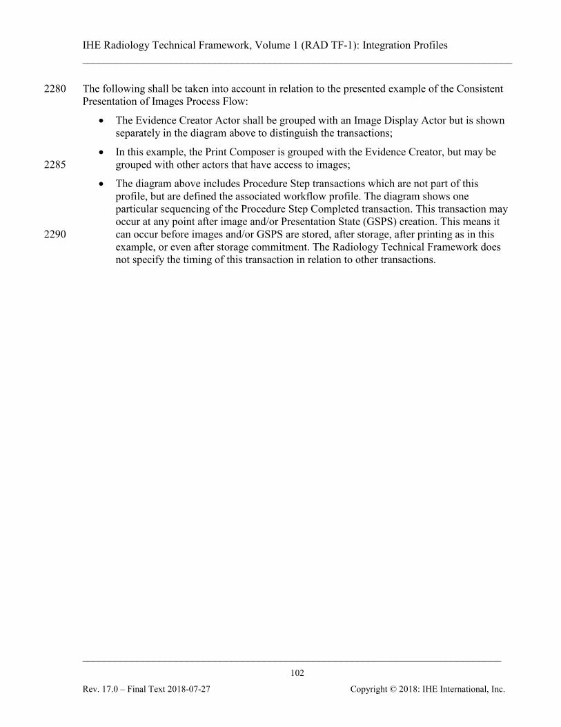
IHE Radiology Technical Framework, Volume 1 (RAD TF-1): Integration Profiles ______________________________________________________________________________
____________________________________________________________________________ 102
Rev. 17.0 – Final Text 2018-07-27 Copyright © 2018: IHE International, Inc.
The following shall be taken into account in relation to the presented example of the Consistent 2280 Presentation of Images Process Flow:
• The Evidence Creator Actor shall be grouped with an Image Display Actor but is shown separately in the diagram above to distinguish the transactions;
• In this example, the Print Composer is grouped with the Evidence Creator, but may be grouped with other actors that have access to images; 2285
• The diagram above includes Procedure Step transactions which are not part of this profile, but are defined the associated workflow profile. The diagram shows one particular sequencing of the Procedure Step Completed transaction. This transaction may occur at any point after image and/or Presentation State (GSPS) creation. This means it can occur before images and/or GSPS are stored, after storage, after printing as in this 2290 example, or even after storage commitment. The Radiology Technical Framework does not specify the timing of this transaction in relation to other transactions.
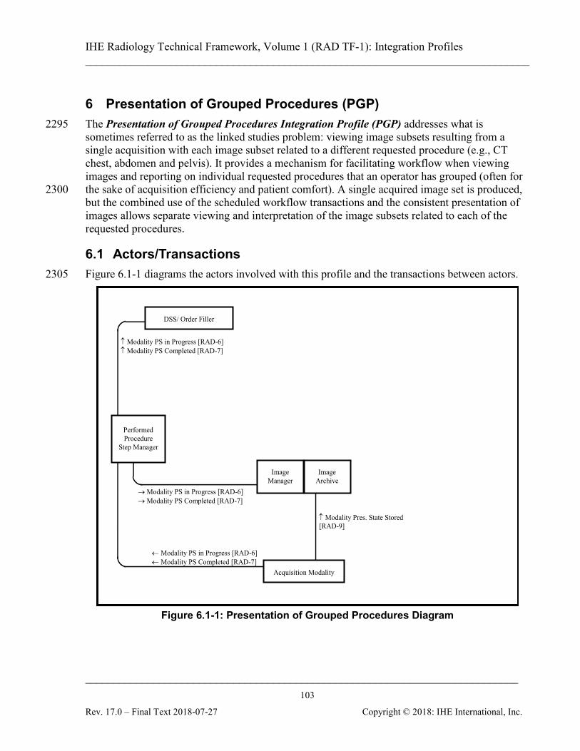
IHE Radiology Technical Framework, Volume 1 (RAD TF-1): Integration Profiles ______________________________________________________________________________
____________________________________________________________________________ 103
Rev. 17.0 – Final Text 2018-07-27 Copyright © 2018: IHE International, Inc.
6 Presentation of Grouped Procedures (PGP) The Presentation of Grouped Procedures Integration Profile (PGP) addresses what is 2295 sometimes referred to as the linked studies problem: viewing image subsets resulting from a single acquisition with each image subset related to a different requested procedure (e.g., CT chest, abdomen and pelvis). It provides a mechanism for facilitating workflow when viewing images and reporting on individual requested procedures that an operator has grouped (often for the sake of acquisition efficiency and patient comfort). A single acquired image set is produced, 2300 but the combined use of the scheduled workflow transactions and the consistent presentation of images allows separate viewing and interpretation of the image subsets related to each of the requested procedures.
6.1 Actors/Transactions Figure 6.1-1 diagrams the actors involved with this profile and the transactions between actors. 2305
↑ Modality Pres. State Stored [RAD-9]
Acquisition Modality
Performed Procedure
Step Manager
Image Manager
Image Archive
↑ Modality PS in Progress [RAD-6] ↑ Modality PS Completed [RAD-7]
→ Modality PS in Progress [RAD-6] → Modality PS Completed [RAD-7]
← Modality PS in Progress [RAD-6] ← Modality PS Completed [RAD-7]
DSS/ Order Filler
Figure 6.1-1: Presentation of Grouped Procedures Diagram
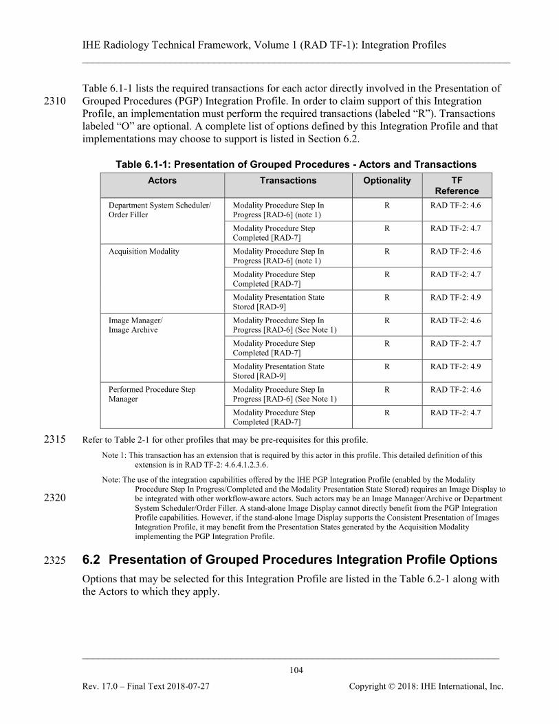
IHE Radiology Technical Framework, Volume 1 (RAD TF-1): Integration Profiles ______________________________________________________________________________
____________________________________________________________________________ 104
Rev. 17.0 – Final Text 2018-07-27 Copyright © 2018: IHE International, Inc.
Table 6.1-1 lists the required transactions for each actor directly involved in the Presentation of Grouped Procedures (PGP) Integration Profile. In order to claim support of this Integration 2310 Profile, an implementation must perform the required transactions (labeled “R”). Transactions labeled “O” are optional. A complete list of options defined by this Integration Profile and that implementations may choose to support is listed in Section 6.2.
Table 6.1-1: Presentation of Grouped Procedures - Actors and Transactions Actors Transactions Optionality TF
Reference Department System Scheduler/ Order Filler
Modality Procedure Step In Progress [RAD-6] (note 1)
R RAD TF-2: 4.6
Modality Procedure Step Completed [RAD-7]
R RAD TF-2: 4.7
Acquisition Modality Modality Procedure Step In Progress [RAD-6] (note 1)
R RAD TF-2: 4.6
Modality Procedure Step Completed [RAD-7]
R RAD TF-2: 4.7
Modality Presentation State Stored [RAD-9]
R RAD TF-2: 4.9
Image Manager/ Image Archive
Modality Procedure Step In Progress [RAD-6] (See Note 1)
R RAD TF-2: 4.6
Modality Procedure Step Completed [RAD-7]
R RAD TF-2: 4.7
Modality Presentation State Stored [RAD-9]
R RAD TF-2: 4.9
Performed Procedure Step Manager
Modality Procedure Step In Progress [RAD-6] (See Note 1)
R RAD TF-2: 4.6
Modality Procedure Step Completed [RAD-7]
R RAD TF-2: 4.7
Refer to Table 2-1 for other profiles that may be pre-requisites for this profile. 2315 Note 1: This transaction has an extension that is required by this actor in this profile. This detailed definition of this
extension is in RAD TF-2: 4.6.4.1.2.3.6.
Note: The use of the integration capabilities offered by the IHE PGP Integration Profile (enabled by the Modality Procedure Step In Progress/Completed and the Modality Presentation State Stored) requires an Image Display to be integrated with other workflow-aware actors. Such actors may be an Image Manager/Archive or Department 2320 System Scheduler/Order Filler. A stand-alone Image Display cannot directly benefit from the PGP Integration Profile capabilities. However, if the stand-alone Image Display supports the Consistent Presentation of Images Integration Profile, it may benefit from the Presentation States generated by the Acquisition Modality implementing the PGP Integration Profile.
6.2 Presentation of Grouped Procedures Integration Profile Options 2325
Options that may be selected for this Integration Profile are listed in the Table 6.2-1 along with the Actors to which they apply.
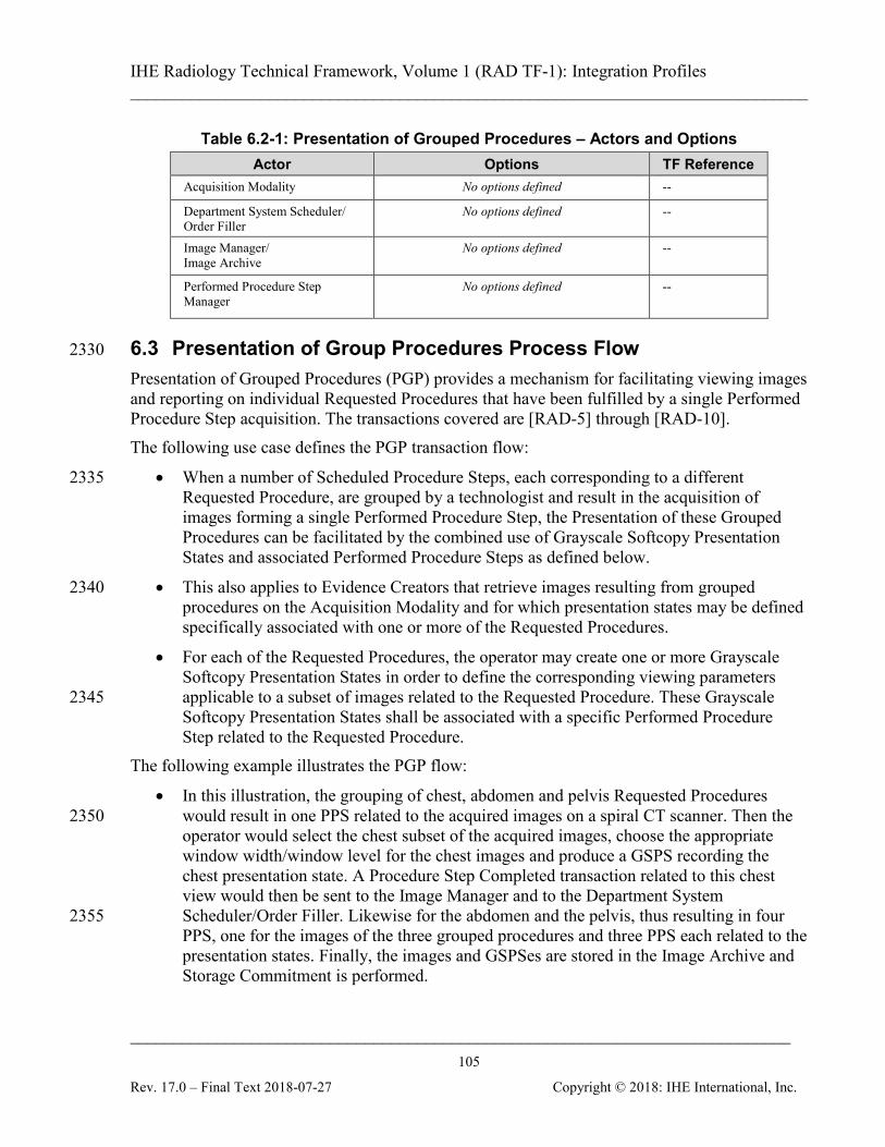
IHE Radiology Technical Framework, Volume 1 (RAD TF-1): Integration Profiles ______________________________________________________________________________
____________________________________________________________________________ 105
Rev. 17.0 – Final Text 2018-07-27 Copyright © 2018: IHE International, Inc.
Table 6.2-1: Presentation of Grouped Procedures – Actors and Options Actor Options TF Reference
Acquisition Modality No options defined --
Department System Scheduler/ Order Filler
No options defined --
Image Manager/ Image Archive
No options defined --
Performed Procedure Step Manager
No options defined --
6.3 Presentation of Group Procedures Process Flow 2330
Presentation of Grouped Procedures (PGP) provides a mechanism for facilitating viewing images and reporting on individual Requested Procedures that have been fulfilled by a single Performed Procedure Step acquisition. The transactions covered are [RAD-5] through [RAD-10]. The following use case defines the PGP transaction flow:
• When a number of Scheduled Procedure Steps, each corresponding to a different 2335 Requested Procedure, are grouped by a technologist and result in the acquisition of images forming a single Performed Procedure Step, the Presentation of these Grouped Procedures can be facilitated by the combined use of Grayscale Softcopy Presentation States and associated Performed Procedure Steps as defined below.
• This also applies to Evidence Creators that retrieve images resulting from grouped 2340 procedures on the Acquisition Modality and for which presentation states may be defined specifically associated with one or more of the Requested Procedures.
• For each of the Requested Procedures, the operator may create one or more Grayscale Softcopy Presentation States in order to define the corresponding viewing parameters applicable to a subset of images related to the Requested Procedure. These Grayscale 2345 Softcopy Presentation States shall be associated with a specific Performed Procedure Step related to the Requested Procedure.
The following example illustrates the PGP flow:
• In this illustration, the grouping of chest, abdomen and pelvis Requested Procedures would result in one PPS related to the acquired images on a spiral CT scanner. Then the 2350 operator would select the chest subset of the acquired images, choose the appropriate window width/window level for the chest images and produce a GSPS recording the chest presentation state. A Procedure Step Completed transaction related to this chest view would then be sent to the Image Manager and to the Department System Scheduler/Order Filler. Likewise for the abdomen and the pelvis, thus resulting in four 2355 PPS, one for the images of the three grouped procedures and three PPS each related to the presentation states. Finally, the images and GSPSes are stored in the Image Archive and Storage Commitment is performed.

IHE Radiology Technical Framework, Volume 1 (RAD TF-1): Integration Profiles ______________________________________________________________________________
____________________________________________________________________________ 106
Rev. 17.0 – Final Text 2018-07-27 Copyright © 2018: IHE International, Inc.
• A reading physician may use the GSPSes (associated with the Requested Procedure indicated in the PPS transaction) created by the technologist to facilitate viewing and 2360 interpreting the CT chest images separately from the CT abdomen images. This will facilitate interpretation as well as reviewing the relevant subset of prior images.
The following sequence of steps describes the typical process flow involved in Presentation of Grouped Procedures:

IHE Radiology Technical Framework, Volume 1 (RAD TF-1): Integration Profiles ______________________________________________________________________________
____________________________________________________________________________ 107
Rev. 17.0 – Final Text 2018-07-27 Copyright © 2018: IHE International, Inc.
Modality Presentation State Stored [RAD-9]
Image Manager/ Image Archive
Acquisition Modality
Department System Scheduler/ Order
Filler
Perform Acquisition
Storage Commitment [RAD-10]
Create GSPS
Query Modality Worklist [RAD-5]
Modality Images Stored [RAD-8]
This set of transactions would be repeated 3 times (once for each of the three presentation states in the example.
Modality Procedure Step In Progress [RAD-6] Modality Procedure Step
In Progress [RAD-6]
Modality Procedure Step Completed [RAD-7] Modality Procedure Step
Completed [RAD-7]
Modality Procedure Step In Progress [RAD-6] Modality Procedure Step
In Progress [RAD-6]
Storage Commitment [RAD-10]
Modality Procedure Step Completed [RAD-7] Modality Procedure Step
Completed [RAD-7]
2365 Figure 6.3-1: Presentation of Grouped Procedures Process Flow
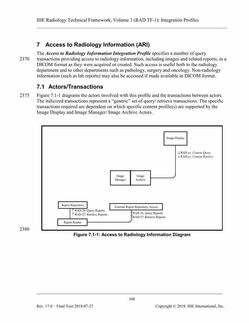
IHE Radiology Technical Framework, Volume 1 (RAD TF-1): Integration Profiles ______________________________________________________________________________
____________________________________________________________________________ 108
Rev. 17.0 – Final Text 2018-07-27 Copyright © 2018: IHE International, Inc.
7 Access to Radiology Information (ARI) The Access to Radiology Information Integration Profile specifies a number of query transactions providing access to radiology information, including images and related reports, in a 2370 DICOM format as they were acquired or created. Such access is useful both to the radiology department and to other departments such as pathology, surgery and oncology. Non-radiology information (such as lab reports) may also be accessed if made available in DICOM format.
7.1 Actors/Transactions Figure 7.1-1 diagrams the actors involved with this profile and the transactions between actors. 2375 The italicized transactions represent a “generic” set of query/ retrieve transactions. The specific transactions required are dependent on which specific content profile(s) are supported by the Image Display and Image Manager/ Image Archive Actors.
↓ RAD-xx: Content Query ↓ RAD-yy: Content Retrieve
Image Display
Image Manager
Image Archive
↑ RAD-26: Query Reports ↑ RAD-27: Retrieve Reports
Report Repository
Report Reader
External Report Repository Access
↑ RAD-26: Query Reports ↑ RAD-27: Retrieve Reports
2380 Figure 7.1-1: Access to Radiology Information Diagram
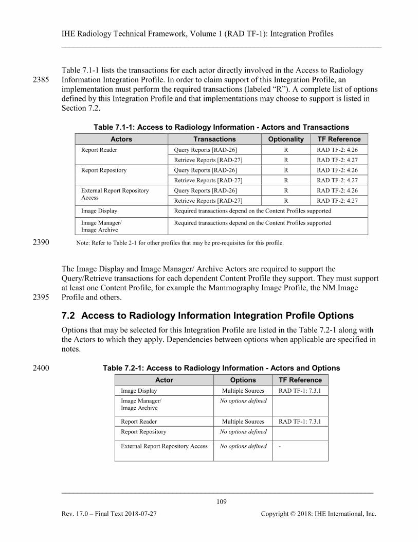
IHE Radiology Technical Framework, Volume 1 (RAD TF-1): Integration Profiles ______________________________________________________________________________
____________________________________________________________________________ 109
Rev. 17.0 – Final Text 2018-07-27 Copyright © 2018: IHE International, Inc.
Table 7.1-1 lists the transactions for each actor directly involved in the Access to Radiology Information Integration Profile. In order to claim support of this Integration Profile, an 2385 implementation must perform the required transactions (labeled “R”). A complete list of options defined by this Integration Profile and that implementations may choose to support is listed in Section 7.2.
Table 7.1-1: Access to Radiology Information - Actors and Transactions Actors Transactions Optionality TF Reference
Report Reader Query Reports [RAD-26] R RAD TF-2: 4.26 Retrieve Reports [RAD-27] R RAD TF-2: 4.27
Report Repository Query Reports [RAD-26] R RAD TF-2: 4.26 Retrieve Reports [RAD-27] R RAD TF-2: 4.27
External Report Repository Access
Query Reports [RAD-26] R RAD TF-2: 4.26 Retrieve Reports [RAD-27] R RAD TF-2: 4.27
Image Display Required transactions depend on the Content Profiles supported
Image Manager/ Image Archive
Required transactions depend on the Content Profiles supported
Note: Refer to Table 2-1 for other profiles that may be pre-requisites for this profile. 2390 The Image Display and Image Manager/ Archive Actors are required to support the Query/Retrieve transactions for each dependent Content Profile they support. They must support at least one Content Profile, for example the Mammography Image Profile, the NM Image Profile and others. 2395
7.2 Access to Radiology Information Integration Profile Options Options that may be selected for this Integration Profile are listed in the Table 7.2-1 along with the Actors to which they apply. Dependencies between options when applicable are specified in notes.
Table 7.2-1: Access to Radiology Information - Actors and Options 2400 Actor Options TF Reference
Image Display Multiple Sources RAD TF-1: 7.3.1 Image Manager/ Image Archive
No options defined
Report Reader Multiple Sources RAD TF-1: 7.3.1 Report Repository No options defined
External Report Repository Access No options defined -
IHE Radiology Technical Framework, Volume 1 (RAD TF-1): Integration Profiles ______________________________________________________________________________
____________________________________________________________________________ 110
Rev. 17.0 – Final Text 2018-07-27 Copyright © 2018: IHE International, Inc.
7.3 Multiple Sources Option This option requires Image Displays and Report Readers to support query and retrieve from multiple information sources in order for a user to gain access to distributed radiology information. Image Displays, in particular, are typically closely associated with, and draw information from, a 2405 single Image Manager/Image Archive. An Image Display that implements this option supports a user that desires to view information consolidated from multiple sources (e.g., ultrasound mini-PACS, cardiology PACS, and radiology PACS). Querying multiple sources also provides an opportunity for an Image Display to access objects stored in a “legacy” archive that has been replaced by, and is possibly having its information 2410 migrated to, a new Image Manager/Image Archive.
7.3.1 Requirements for the Multiple Sources Option In order to claim support for this profile option, an Image Display shall be able to query and retrieve from multiple Image Manager/Image Archives. In order to claim support for this profile option, a Report Reader shall be able to query and 2415 retrieve from multiple Report Repositories. There is no requirement as to whether the multiple queries or retrieves are done concurrently or sequentially. Image Displays and Report Readers shall have the ability to be configured to access multiple Image Manager/Image Archives and Report Repositories (respectively). 2420 Image Managers and Report Managers shall also support the Patient Information Reconciliation integration profile in order to ensure that the information gathered from them is as accurate as possible. Since having actors in different ADT (patient identifier) domains could result in unpredictable query results, this option assumes that all actors are members of the same ADT domain (i.e., it can be assumed that a given patient identifier uniquely refers to a single patient). 2425 An Image Display or Report Reader supporting this profile option may be configured to initially query only its local information source; however, it shall be possible to query multiple sources with a single user request. When an Image Display and Report Reader are combined, a single user request shall suffice to trigger a query of multiple sources for both images (and anything else stored in an Image 2430 Manager/Image Archive) and reports. If communication with an information source fails, an Image Display or Report Reader shall provide the information it received from the other sources. In addition, the Image Display and Report Reader shall inform the user that they are viewing potentially incomplete results. When an Image Display or Report Reader performs a study-level or series-level query to 2435 multiple sources and finds the study/series referenced in multiple places, the study/series is either duplicated or the study/series is split across the systems. When the user requests a retrieval of the study/series an Image Display and Report Reader shall collate the information, determine if the

IHE Radiology Technical Framework, Volume 1 (RAD TF-1): Integration Profiles ______________________________________________________________________________
____________________________________________________________________________ 111
Rev. 17.0 – Final Text 2018-07-27 Copyright © 2018: IHE International, Inc.
information is actually duplicated or split, and present to the user a consolidated view of results. The consolidated view of results may be shown and updated either as responses are received or 2440 when the final response has been received from the last responding information source. A participating Image Display or Report Reader shall manage duplicate instances in a manner that avoids redundant retrieval. 2445
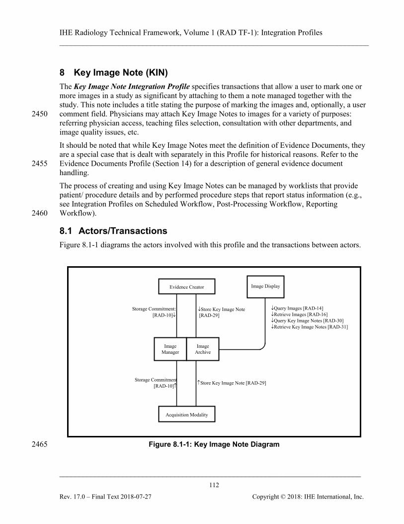
IHE Radiology Technical Framework, Volume 1 (RAD TF-1): Integration Profiles ______________________________________________________________________________
____________________________________________________________________________ 112
Rev. 17.0 – Final Text 2018-07-27 Copyright © 2018: IHE International, Inc.
8 Key Image Note (KIN) The Key Image Note Integration Profile specifies transactions that allow a user to mark one or more images in a study as significant by attaching to them a note managed together with the study. This note includes a title stating the purpose of marking the images and, optionally, a user comment field. Physicians may attach Key Image Notes to images for a variety of purposes: 2450 referring physician access, teaching files selection, consultation with other departments, and image quality issues, etc. It should be noted that while Key Image Notes meet the definition of Evidence Documents, they are a special case that is dealt with separately in this Profile for historical reasons. Refer to the Evidence Documents Profile (Section 14) for a description of general evidence document 2455 handling. The process of creating and using Key Image Notes can be managed by worklists that provide patient/ procedure details and by performed procedure steps that report status information (e.g., see Integration Profiles on Scheduled Workflow, Post-Processing Workflow, Reporting Workflow). 2460
8.1 Actors/Transactions Figure 8.1-1 diagrams the actors involved with this profile and the transactions between actors.
↓Query Images [RAD-14] ↓Retrieve Images [RAD-16] ↓Query Key Image Notes [RAD-30] ↓Retrieve Key Image Notes [RAD-31]
Image Display
Storage Commitment: [RAD-10]↓
↑Store Key Image Note [RAD-29] Storage Commitment
[RAD-10]↑
↓Store Key Image Note [RAD-29]
Evidence Creator
Acquisition Modality
Image Manager
Image Archive
Figure 8.1-1: Key Image Note Diagram 2465
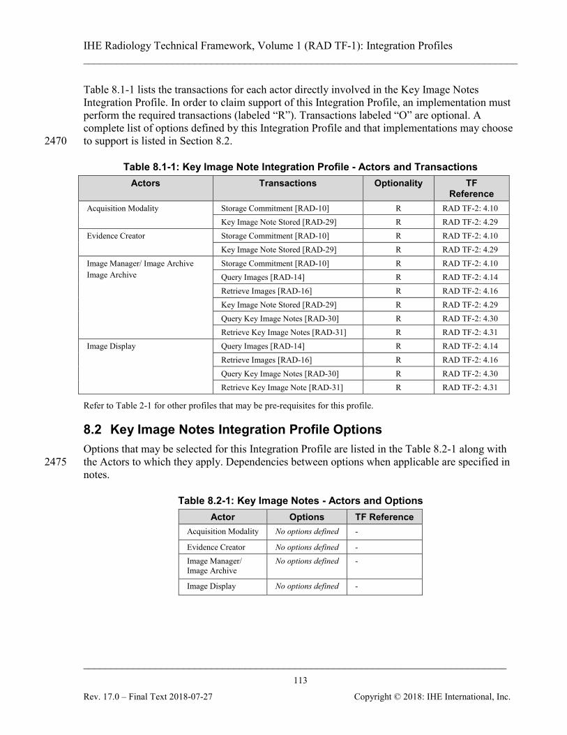
IHE Radiology Technical Framework, Volume 1 (RAD TF-1): Integration Profiles ______________________________________________________________________________
____________________________________________________________________________ 113
Rev. 17.0 – Final Text 2018-07-27 Copyright © 2018: IHE International, Inc.
Table 8.1-1 lists the transactions for each actor directly involved in the Key Image Notes Integration Profile. In order to claim support of this Integration Profile, an implementation must perform the required transactions (labeled “R”). Transactions labeled “O” are optional. A complete list of options defined by this Integration Profile and that implementations may choose to support is listed in Section 8.2. 2470
Table 8.1-1: Key Image Note Integration Profile - Actors and Transactions Actors Transactions Optionality TF
Reference Acquisition Modality Storage Commitment [RAD-10] R RAD TF-2: 4.10
Key Image Note Stored [RAD-29] R RAD TF-2: 4.29 Evidence Creator Storage Commitment [RAD-10] R RAD TF-2: 4.10
Key Image Note Stored [RAD-29] R RAD TF-2: 4.29 Image Manager/ Image Archive Image Archive
Storage Commitment [RAD-10] R RAD TF-2: 4.10 Query Images [RAD-14] R RAD TF-2: 4.14 Retrieve Images [RAD-16] R RAD TF-2: 4.16 Key Image Note Stored [RAD-29] R RAD TF-2: 4.29 Query Key Image Notes [RAD-30] R RAD TF-2: 4.30 Retrieve Key Image Notes [RAD-31] R RAD TF-2: 4.31
Image Display Query Images [RAD-14] R RAD TF-2: 4.14 Retrieve Images [RAD-16] R RAD TF-2: 4.16 Query Key Image Notes [RAD-30] R RAD TF-2: 4.30 Retrieve Key Image Note [RAD-31] R RAD TF-2: 4.31
Refer to Table 2-1 for other profiles that may be pre-requisites for this profile.
8.2 Key Image Notes Integration Profile Options Options that may be selected for this Integration Profile are listed in the Table 8.2-1 along with the Actors to which they apply. Dependencies between options when applicable are specified in 2475 notes.
Table 8.2-1: Key Image Notes - Actors and Options Actor Options TF Reference
Acquisition Modality No options defined -
Evidence Creator No options defined - Image Manager/ Image Archive
No options defined -
Image Display No options defined -
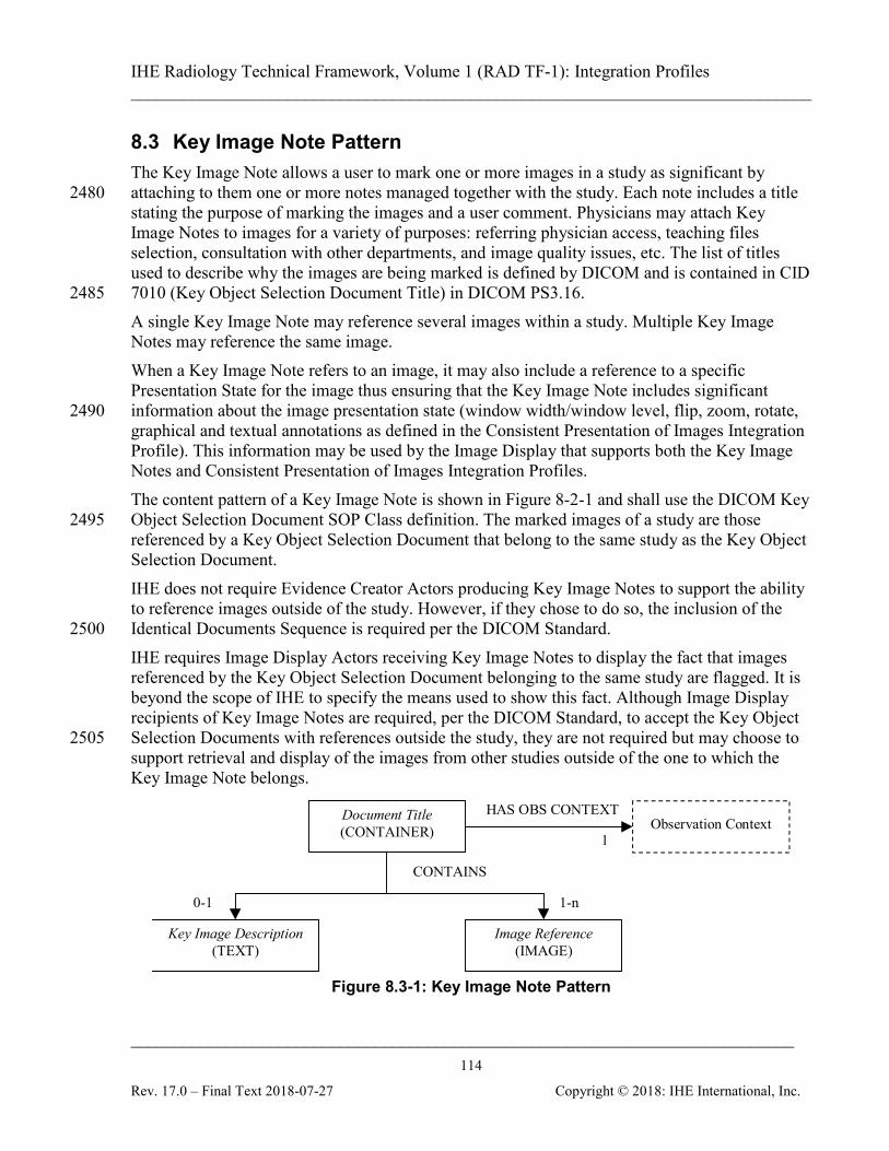
IHE Radiology Technical Framework, Volume 1 (RAD TF-1): Integration Profiles ______________________________________________________________________________
____________________________________________________________________________ 114
Rev. 17.0 – Final Text 2018-07-27 Copyright © 2018: IHE International, Inc.
8.3 Key Image Note Pattern The Key Image Note allows a user to mark one or more images in a study as significant by attaching to them one or more notes managed together with the study. Each note includes a title 2480 stating the purpose of marking the images and a user comment. Physicians may attach Key Image Notes to images for a variety of purposes: referring physician access, teaching files selection, consultation with other departments, and image quality issues, etc. The list of titles used to describe why the images are being marked is defined by DICOM and is contained in CID 7010 (Key Object Selection Document Title) in DICOM PS3.16. 2485 A single Key Image Note may reference several images within a study. Multiple Key Image Notes may reference the same image. When a Key Image Note refers to an image, it may also include a reference to a specific Presentation State for the image thus ensuring that the Key Image Note includes significant information about the image presentation state (window width/window level, flip, zoom, rotate, 2490 graphical and textual annotations as defined in the Consistent Presentation of Images Integration Profile). This information may be used by the Image Display that supports both the Key Image Notes and Consistent Presentation of Images Integration Profiles. The content pattern of a Key Image Note is shown in Figure 8-2-1 and shall use the DICOM Key Object Selection Document SOP Class definition. The marked images of a study are those 2495 referenced by a Key Object Selection Document that belong to the same study as the Key Object Selection Document. IHE does not require Evidence Creator Actors producing Key Image Notes to support the ability to reference images outside of the study. However, if they chose to do so, the inclusion of the Identical Documents Sequence is required per the DICOM Standard. 2500 IHE requires Image Display Actors receiving Key Image Notes to display the fact that images referenced by the Key Object Selection Document belonging to the same study are flagged. It is beyond the scope of IHE to specify the means used to show this fact. Although Image Display recipients of Key Image Notes are required, per the DICOM Standard, to accept the Key Object Selection Documents with references outside the study, they are not required but may choose to 2505 support retrieval and display of the images from other studies outside of the one to which the Key Image Note belongs.
Document Title(CONTAINER)
0-1 1-n
CONTAINS
HAS OBS CONTEXT
1
Image Reference(IMAGE)
Observation Context
Key Image Description(TEXT)
Figure 8.3-1: Key Image Note Pattern
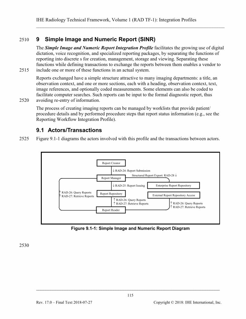
IHE Radiology Technical Framework, Volume 1 (RAD TF-1): Integration Profiles ______________________________________________________________________________
____________________________________________________________________________ 115
Rev. 17.0 – Final Text 2018-07-27 Copyright © 2018: IHE International, Inc.
9 Simple Image and Numeric Report (SINR) 2510
The Simple Image and Numeric Report Integration Profile facilitates the growing use of digital dictation, voice recognition, and specialized reporting packages, by separating the functions of reporting into discrete s for creation, management, storage and viewing. Separating these functions while defining transactions to exchange the reports between them enables a vendor to include one or more of these functions in an actual system. 2515 Reports exchanged have a simple structure attractive to many imaging departments: a title, an observation context, and one or more sections, each with a heading, observation context, text, image references, and optionally coded measurements. Some elements can also be coded to facilitate computer searches. Such reports can be input to the formal diagnostic report, thus avoiding re-entry of information. 2520 The process of creating imaging reports can be managed by worklists that provide patient/ procedure details and by performed procedure steps that report status information (e.g., see the Reporting Workflow Integration Profile).
9.1 Actors/Transactions Figure 9.1-1 diagrams the actors involved with this profile and the transactions between actors. 2525
↓ RAD-24: Report Submission Structured Report Export: RAD-28 ↓
↓ RAD-25: Report Issuing
Report Creator
↑ RAD-26: Query Reports ↑ RAD-27: Retrieve Reports
↑ RAD-26: Query Reports ↑ RAD-27: Retrieve Reports
Report Repository
Report Reader
External Report Repository Access
Report Manager
Enterprise Report Repository
↑ RAD-26: Query Reports ↑ RAD-27: Retrieve Reports
Figure 9.1-1: Simple Image and Numeric Report Diagram
2530
IHE Radiology Technical Framework, Volume 1 (RAD TF-1): Integration Profiles ______________________________________________________________________________
____________________________________________________________________________ 116
Rev. 17.0 – Final Text 2018-07-27 Copyright © 2018: IHE International, Inc.
Table 9.1-1 lists the transactions for each actor directly involved in the Simple Image and Numeric Report Integration Profile. In order to claim support of this Integration Profile, an implementation must perform the required transactions (labeled “R”). Transactions labeled “O” are optional. A complete list of options defined by this Integration Profile and that implementations may choose to support is listed in Section 9.2. 2535
Table 9.1-1: Simple Image and Numeric Report - Actors and Transactions Actors Transactions Optionality TF
Reference Report Creator Report Submission [RAD-24] R RAD TF-2: 4.24 Report Manager Report Submission [RAD-24] R RAD TF-2: 4.24
Report Issuing [RAD-25] R RAD TF-2: 4.25 Query Reports [RAD-26] R RAD TF-2: 4.26 Retrieve Reports [RAD-27] R RAD TF-2: 4.27 Structured Report Export [RAD-28]
O RAD TF-2: 4.28
Report Reader Query Reports [RAD-26] R RAD TF-2: 4.26 Retrieve Reports [RAD-27] R RAD TF-2: 4.27
Report Repository Report Issuing [RAD-25] R RAD TF-2: 4.25 Query Reports [RAD-26] R RAD TF-2: 4.26 Retrieve Reports [RAD-27] R RAD TF-2: 4.27
External Report Repository Access
Query Reports [RAD-26] R RAD TF-2: 4.26 Retrieve Reports [RAD-27] R RAD TF-2: 4.27
Enterprise Report Repository Structured Report Export [RAD-28]
R RAD TF-2: 4.28
Refer to Table 2-1 for other profiles that may be pre-requisites for this profile.
9.2 Simple Image and Numeric Report Integration Profile Options Options that may be selected for this Integration Profile are listed in the Table 9.2-1 along with 2540 the actors to which they apply. Dependencies between options when applicable are specified in notes.
Table 9.2-1: Simple Image and Numeric Report - Actors and Options Actor Options TF Reference
Enterprise Report Repository No options defined - External Report Repository Access No options defined - Report Creator Enhanced SR RAD TF-2: 4.24.4.1.2 Report Manager No options defined - Report Reader Enhanced SR RAD TF-2: 4.27.4.2.2 Report Repository No options defined -

IHE Radiology Technical Framework, Volume 1 (RAD TF-1): Integration Profiles ______________________________________________________________________________
____________________________________________________________________________ 117
Rev. 17.0 – Final Text 2018-07-27 Copyright © 2018: IHE International, Inc.
The Report Creator, Report Manager and Report Repository will likely support a variety of 2545 DICOM SOP Classes. It is expected that this level of optionality will be documented by a reference in the IHE Integration Statement (see Appendix D).
9.3 Diagnostic Report Process Flow This section describes the typical process flow related to diagnostic reporting. The transactions covered are [RAD-24] through [RAD-27]. 2550 In the initial stage of diagnostic reporting, a reading physician records the diagnosis by generating a draft DICOM Structured Report object, which is submitted to the Report Manager. Once a report is sent to the Report Manager, the Report Creator relinquishes control of the report to the Report Manager. There are other documents which are sometimes referred to as “reports” and may be encoded 2555 using DICOM SR (for example, procedure reports, CAD results and echocardiography measurement reports) however such documents do not follow the same kind of verification and distribution process described in this profile. These other documents serve different purposes and are instead addressed in the Evidence Documents Profile. Reports are processed and modified by the Report Manager. This involves adding and changing 2560 report data as well as verifying draft reports. In all cases, any change in the report content by the Report Manager leads to the creation of a new DICOM Structured Report object. At any time, the Report Manager can transmit reports to the Report Repository for external access, but at a minimum the final report must be sent to the Report Repository. A Report Creator can effectively amend a report by submitting a new SR SOP Instance. 2565 The Report Repository provides permanent storage of DICOM Structured Reports. It also allows reports to be queried and retrieved throughout the enterprise by Report Readers. A Report Reader provides a user interface to view DICOM Structured Reports that it retrieves from the Report Repository or External Report Repository Access. The External Report Repository Access is a gateway to obtain other enterprise department 2570 reports, such as Laboratory and Pathology, from within the Imaging department. DICOM Structured Reports are queried and retrieved by a Report Reader from the External Report Repository Access. The Enterprise Report Repository receives diagnostic reports in HL7 format. The Simple Image Report and Simple Image and Numeric Reports are required minimally to 2575 have the functionality defined in template TID 2000. Creators may introduce increased complexity as long as it conforms to the SOP class. The templates referenced in the Technical Framework are included in DICOM Part 16.

IHE Radiology Technical Framework, Volume 1 (RAD TF-1): Integration Profiles ______________________________________________________________________________
____________________________________________________________________________ 118
Rev. 17.0 – Final Text 2018-07-27 Copyright © 2018: IHE International, Inc.
Report Creation
Report Submission [RAD-24]
Report Issuing [RAD-25]
Report Creator
Report Manager
Report Repository
Retrieve Reports [RAD-27]
Report Reader
External Report Repository
Access
Query Reports [RAD-26]
Enterprise Report
Repository
Report Modification or Verification
Structured Report Export [RAD-28]
View Reports
View Reports
Report Issuing [RAD-25]
Retrieve Reports [RAD-27]
Query Reports [RAD-26]
2580 Figure 9.3-1: Diagnostic Reporting Process Flow
IHE Radiology Technical Framework, Volume 1 (RAD TF-1): Integration Profiles ______________________________________________________________________________
____________________________________________________________________________ 119
Rev. 17.0 – Final Text 2018-07-27 Copyright © 2018: IHE International, Inc.
9.4 Diagnostic Reporting Use Cases DICOM Structured Reports offer the capability to encode arbitrarily structured diagnostic report data. The Radiology Technical Framework stipulates that the reporting actors need to support several use cases and their specific content patterns, which are detailed in the following sections. 2585 The diagrams in the following sections define the report content pattern and utilize the following conventions:
• Each rectangle is a single Content Item.
• Italic text in a rectangle denotes a generic grouping of Concept Names to be used for the Content Item. These must be configurable in the reporting actors. 2590
• Uppercase text in a rectangle denotes the Content Item Value Type.
• Text following the Content Item Value Type specifies the possible Content Item Value(s), if known (only used for Observation Context).
• Text on lines defines the relationship between Content Items.
• Numbers on lines define the cardinality of descendent Content Items. 2595
9.4.1 Simple Image Report The Simple Image Report allows documents with multiple sections (with headings) containing report text and references to relevant images. Some text items of these documents may also be related to specific images. This allows a reading physician to identify one or more images from which their conclusions were inferred. This content pattern is shown in Figure 9.4-1 and shall 2600 use the DICOM Basic Text SR Information Object Definition and Basic Image Diagnostic Report Template (TID 2000 in DICOM PS3.16). Note that TID 2000 has other requirements not shown in the diagram.
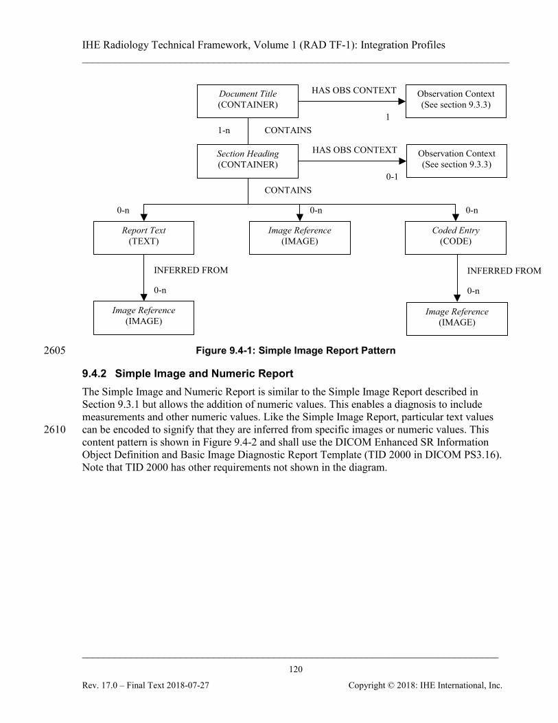
IHE Radiology Technical Framework, Volume 1 (RAD TF-1): Integration Profiles ______________________________________________________________________________
____________________________________________________________________________ 120
Rev. 17.0 – Final Text 2018-07-27 Copyright © 2018: IHE International, Inc.
0-n
CONTAINS
HAS OBS CONTEXT
1
CONTAINS
0-n
0-n
INFERRED FROM
Report Text (TEXT)
Image Reference (IMAGE)
Observation Context (See section 9.3.3)
1-n
Section Heading (CONTAINER)
Document Title (CONTAINER)
Image Reference (IMAGE)
HAS OBS CONTEXT
0-1
Observation Context (See section 9.3.3)
0-n
Coded Entry (CODE)
0-n
INFERRED FROM
Image Reference (IMAGE)
Figure 9.4-1: Simple Image Report Pattern 2605
9.4.2 Simple Image and Numeric Report The Simple Image and Numeric Report is similar to the Simple Image Report described in Section 9.3.1 but allows the addition of numeric values. This enables a diagnosis to include measurements and other numeric values. Like the Simple Image Report, particular text values can be encoded to signify that they are inferred from specific images or numeric values. This 2610 content pattern is shown in Figure 9.4-2 and shall use the DICOM Enhanced SR Information Object Definition and Basic Image Diagnostic Report Template (TID 2000 in DICOM PS3.16). Note that TID 2000 has other requirements not shown in the diagram.
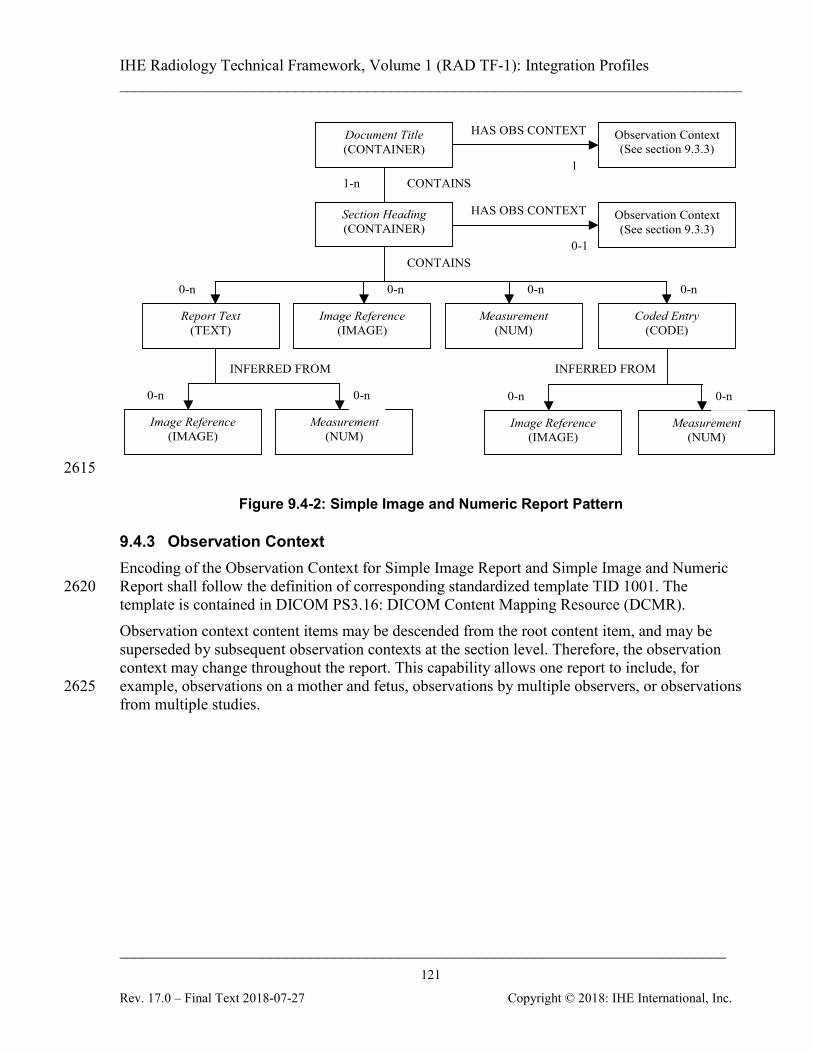
IHE Radiology Technical Framework, Volume 1 (RAD TF-1): Integration Profiles ______________________________________________________________________________
____________________________________________________________________________ 121
Rev. 17.0 – Final Text 2018-07-27 Copyright © 2018: IHE International, Inc.
0-n
CONTAINS
HAS OBS CONTEXT
1
CONTAINS
0-n
0-n
INFERRED FROM
Report Text (TEXT)
Image Reference (IMAGE)
Observation Context (See section 9.3.3)
1-n
Section Heading (CONTAINER)
Document Title (CONTAINER)
Image Reference (IMAGE)
Measurement (NUM)
0-n
Measurement (NUM)
0-n
HAS OBS CONTEXT
0-1
Observation Context (See section 9.3.3)
0-n
Coded Entry (CODE)
0-n
INFERRED FROM
Image Reference (IMAGE)
Measurement (NUM)
0-n
2615
Figure 9.4-2: Simple Image and Numeric Report Pattern
9.4.3 Observation Context Encoding of the Observation Context for Simple Image Report and Simple Image and Numeric Report shall follow the definition of corresponding standardized template TID 1001. The 2620 template is contained in DICOM PS3.16: DICOM Content Mapping Resource (DCMR). Observation context content items may be descended from the root content item, and may be superseded by subsequent observation contexts at the section level. Therefore, the observation context may change throughout the report. This capability allows one report to include, for example, observations on a mother and fetus, observations by multiple observers, or observations 2625 from multiple studies.
IHE Radiology Technical Framework, Volume 1 (RAD TF-1): Integration Profiles ______________________________________________________________________________
____________________________________________________________________________ 122
Rev. 17.0 – Final Text 2018-07-27 Copyright © 2018: IHE International, Inc.
10 Basic Security (SEC) - DEPRECATED This profile has been superseded by the Radiology Audit Trail Option in ITI-Audit Trail and Node Authentication Profile (see RAD TF-3: 5.1 for a detailed description of the Radiology Audit Trail Option). 2630
IHE Radiology Technical Framework, Volume 1 (RAD TF-1): Integration Profiles ______________________________________________________________________________
____________________________________________________________________________ 123
Rev. 17.0 – Final Text 2018-07-27 Copyright © 2018: IHE International, Inc.
11 Charge Posting (CHG) The Charge Posting Integration Profile specifies information exchange from the Department System Scheduler/Order Filler to the Charge Processor about charges associated with particular 2635 procedures, as well as communication about patient demographics, accounts, insurance, and guarantors between ADT Patient Registration and Charge Processor. The Charge Posted Transaction contains some information to generate a claim. Currently, these interfaces contain fixed field formatted or HL7-like data. The goal of including this in the Radiology Technical Framework is to standardize interface between clinical systems and the Charge Processors. 2640 Additionally, the Charge Posted Transaction reduces the need of the billing system to have knowledge of the radiology internals. The result is that the Charge Processor will receive more complete, timely and accurate data. The Department System Scheduler/Order Filler indicates to the Charge Processor that procedures are available for Technical and/or Professional billing. The Charge Posted transaction may occur 2645 at various times in the workflow. Regulations and site operating procedures determine when a procedure is eligible for Charge Posting. Often, the events are different for technical and professional charges. Technical charges are typically eligible at procedure completion. Professional charges are typically eligible at result verification. 2650 Events that may trigger charges are Procedure Ordered, Procedure Scheduled, Procedure Completed, Result Dictated, Result Transcribed, and Result Verified.

IHE Radiology Technical Framework, Volume 1 (RAD TF-1): Integration Profiles ______________________________________________________________________________
____________________________________________________________________________ 124
Rev. 17.0 – Final Text 2018-07-27 Copyright © 2018: IHE International, Inc.
11.1 Actors/Transactions 2655
↓ RAD-36: Account Management
ADT
Acquisition Modality
Performed Procedure
Step Manager
↑ RAD-6: Modality PS In Progress ↑ RAD-7: Modality PS Completed ↑ RAD-20: Creator PS In Progress ↑ RAD-21: Creator PS Completed ↑ RAD-59 Import PS In Progress ↑ RAD-60: Import PS Completed
← RAD-6: Modality PS In Progress ← RAD-7: Modality PS Completed
DSS/Order Filler
Charge Processor → RAD-35: Charge Posted
Report Manager
Evidence Creator
← RAD-20: Creator PS In Progress ← RAD-21: Creator PS Completed
↓ RAD-42: Performed Work Status Update
Post-Processing Manager
↑ RAD-39: Workitem Completed
Importer
← RAD-59 Import PS In Progress ← RAD-60: Import PS Completed
Figure 11.1-1: Charge Posting Transaction Diagram
Table 11.1-1 lists the transactions for each actor directly involved in the Charge Posted Profile. In order to claim support of this Integration Profile, an implementation must perform the required transactions (labeled “R”). Transactions labeled “O” are optional. A complete list of 2660 options defined by this Integration Profile and that implementations may choose to support is listed in Section 11.2.
Table 11.1-1: Charge Posting – Actors and Transactions Actors Transactions Optionality TF Reference
ADT Patient Registration Account Management [RAD-36] R RAD TF-3: 4.36 Department System Scheduler/ Order Filler/Performed
Charge Posted [RAD-35] (note 5) R RAD TF-3: 4.35 Modality Procedure Step In Progress [RAD-6]
R RAD TF-2: 4.6

IHE Radiology Technical Framework, Volume 1 (RAD TF-1): Integration Profiles ______________________________________________________________________________
____________________________________________________________________________ 125
Rev. 17.0 – Final Text 2018-07-27 Copyright © 2018: IHE International, Inc.
Actors Transactions Optionality TF Reference Procedure Step Manager (note 3)
Modality Procedure Step Completed [RAD-7] (note 2)
R RAD TF-2: 4.7
Creator PS In Progress [RAD-20] R RAD TF-2: 4.20 Creator PS Completed [RAD-21] R RAD TF-2: 4.21 Performed Work Status Update [RAD-42]
R RAD TF-3: 4.42
Import Procedure Step In Progress [RAD-59]
R RAD TF-3: 4.59
Import Procedure Step Completed [RAD-60] (note 4)
R RAD TF-3: 4.60
Acquisition Modality
Modality Procedure Step In Progress [RAD-6] (note 1)
R RAD TF-2: 4.6
Modality Procedure Step Completed [RAD-7]
R RAD TF-2: 4.7
Report Manager Performed Work Status Update [RAD-42]
R RAD TF-3: 4.42
Evidence Creator Creator PS In Progress [RAD-20] R RAD TF-2: 4.20 Creator PS Completed [RAD-21] R RAD TF-2: 4.21 Post-Processing Manager (note 3)
Workitem Completed [RAD-39] R RAD TF-3: 4.39
Charge Processor Charge Posted [RAD-35] (note 5) R RAD TF-3: 4.35 Account Management [RAD-36] R RAD TF-3: 4.36
Importer Import Procedure Step In Progress [RAD-59]
R RAD TF-3: 4.59
Import Procedure Step Completed [RAD-60] (note 4)
R RAD TF-3: 4.60
Note: Refer to Table 2-1 for other profiles that may be pre-requisites for this profile.
Note 1: An Acquisition Modality that claims the Charge Posting Profile shall support the Assisted Protocol Setting Option 2665 (see RAD TF-2: 4.6.4.1.2.4.2).
Note 2: In the transaction, the DSS/Order Filler shall use the Billing and Material Management information supplied by the Acquisition Modality (see RAD TF-2: 4.7.4.1.3.2) or the Importer (see RAD TF-2: 4.7.4.1.3.2 and RAD TF-3: 4.60.4.1.3.2)
Note 3: The Post-Processing Manager participates in this profile only if the Post Processing Workflow Integration Profile is 2670 one of the pre-requisite profiles supported. In this case, the Post-Processing Manager shall be grouped with the DSS/ Order Filler.
Note 4: To claim the Charge Posting Profile, the Importer shall support the Billing and Material Management Option (see RAD TF-3: 4.60.4.1.2.3).
Note 5: The DSS/Order Filler and Charge Processor shall support the HL7v2.3.1 semantics for [RAD-35]. (See RAD TF-3: 2675 4.35.4.1.2).
11.2 Charge Posting Integration Profile Options Options that may be selected for this Integration Profile are listed in the Table 11.2-1 along with the Actors to which they apply. Dependencies between options when applicable are specified in notes. 2680
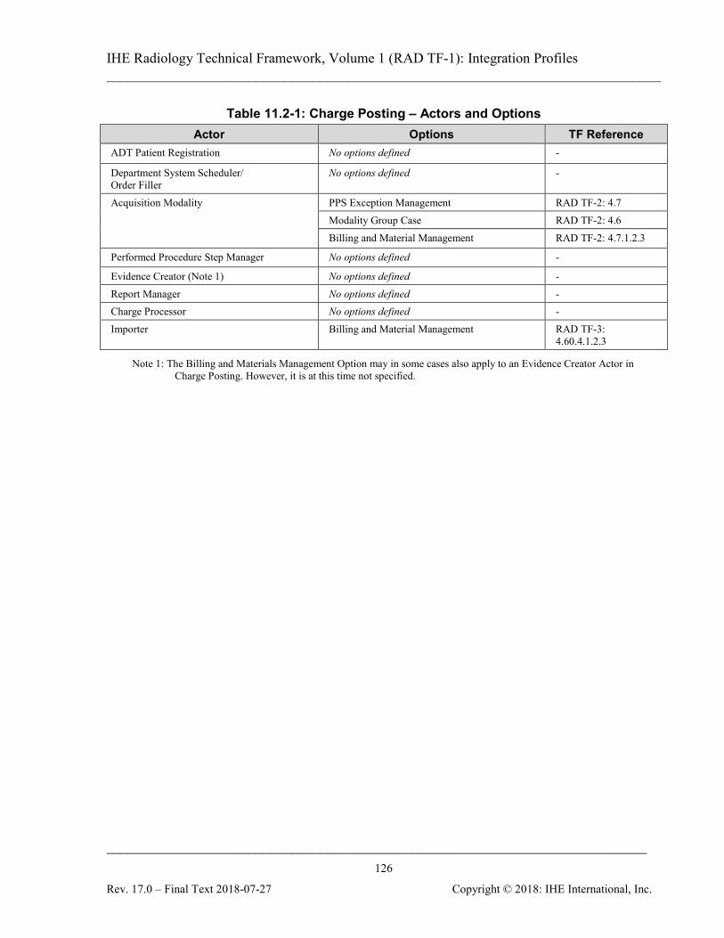
IHE Radiology Technical Framework, Volume 1 (RAD TF-1): Integration Profiles ______________________________________________________________________________
____________________________________________________________________________ 126
Rev. 17.0 – Final Text 2018-07-27 Copyright © 2018: IHE International, Inc.
Table 11.2-1: Charge Posting – Actors and Options Actor Options TF Reference
ADT Patient Registration No options defined -
Department System Scheduler/ Order Filler
No options defined -
Acquisition Modality PPS Exception Management RAD TF-2: 4.7 Modality Group Case RAD TF-2: 4.6 Billing and Material Management RAD TF-2: 4.7.1.2.3
Performed Procedure Step Manager No options defined -
Evidence Creator (Note 1) No options defined - Report Manager No options defined - Charge Processor No options defined - Importer Billing and Material Management RAD TF-3:
4.60.4.1.2.3
Note 1: The Billing and Materials Management Option may in some cases also apply to an Evidence Creator Actor in Charge Posting. However, it is at this time not specified.
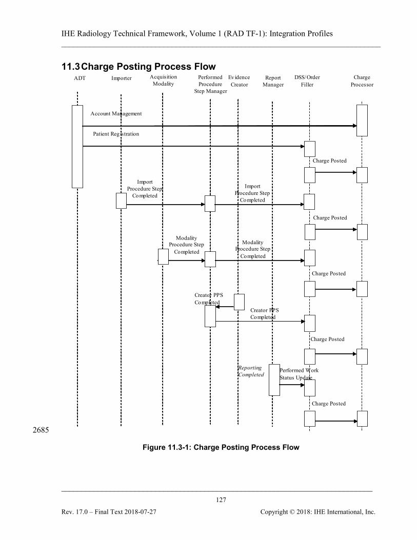
IHE Radiology Technical Framework, Volume 1 (RAD TF-1): Integration Profiles ______________________________________________________________________________
____________________________________________________________________________ 127
Rev. 17.0 – Final Text 2018-07-27 Copyright © 2018: IHE International, Inc.
11.3 Charge Posting Process Flow Performed
Procedure Step Manager
Acquisition Modality
Charge Processor
DSS/Order Filler
Reporting Completed
ADT
Charge Posted
Report Manager
Creator PPS Completed
Patient Reg istration
Account Management
Charge Posted
Modality Procedure Step
Completed
Modality Procedure Step
Completed
Charge Posted
Charge Posted
Ev idence Creator
Performed Work Status Update
Creator PPS Completed
Charge Posted
Import Procedure Step
Completed
Import Procedure Step
Completed
Importer
2685
Figure 11.3-1: Charge Posting Process Flow

IHE Radiology Technical Framework, Volume 1 (RAD TF-1): Integration Profiles ______________________________________________________________________________
____________________________________________________________________________ 128
Rev. 17.0 – Final Text 2018-07-27 Copyright © 2018: IHE International, Inc.
Events that may trigger a charge posted transaction are Procedure Ordered, Procedure Scheduled, Procedure Completed, Result Dictated, Result Transcribed, and Result Verified.
11.3.1 Use Cases 2690 This section describes the potential use cases relating to the charge posting functionality. It is the responsibility of the Department System Scheduler/Order Filler to ensure that the billing information is sent to the Charge Processor. The Department System Scheduler/Order Filler forwards the data that is required by the Charge Processor to generate the claim. The Charge Processor shall accept the Charge Posted Transaction information. Interpretation and 2695 subsequent billing processes by the Charge Processor are beyond the scope of this profile. Below are listed the typical use cases:
• A Department System Scheduler/Order Filler makes technical charges available for posting when the modality has completed the procedure.
• A Department System Scheduler/Order Filler makes professional charges available for 2700 posting at time of report verification.
• A site makes both technical and professional charges available at time of result verification.
• A site may have a single charge that comprises both the technical and professional components. 2705
11.3.2 Technical Billing Technical charges are based on the procedure and often include typical materials usage. These are one or more charges that are included in the Charge Posted Transaction. The Charge Posted Transaction message can be sent immediately when the Department System Scheduler/Order Filler receives confirmation that the procedure is completed. Additionally, a site may wish to 2710 send information on materials used during a procedure to the Charge Processor for inclusion with the technical charges. Note that it may be site policy to verify from the Image Manager that the images have been stored. This is dependent on the business rules established for that site.
11.3.3 Professional Billing 2715 Professional charges are based on the reading physician providing the results for the procedure. These are one or more charges that are included in the Charge Posted Transaction. The Professional Billing Charge Posted Transaction can be sent any time after the Department System Scheduler/Order Filler receives confirmation from the Report Manager that the report has been completed and verified. This may be done by grouping the Report Manager with 2720 Department System Scheduler. Note that IHE specifies a non-country specific procedure coding scheme. The Charge Posted Transaction defines the below sources of information:
IHE Radiology Technical Framework, Volume 1 (RAD TF-1): Integration Profiles ______________________________________________________________________________
____________________________________________________________________________ 129
Rev. 17.0 – Final Text 2018-07-27 Copyright © 2018: IHE International, Inc.
• Patient Order Information
• Scheduling and Requested Procedure 2725
• Scheduling and Scheduled Procedure Step
• Modality Performed Procedure Step
• Status Information - Completed / Discontinued
• Protocol Code
• Consumables 2730
• Optionally, additional manual input or processing by the Department System Scheduler/Order Filler
11.4 Data Model for Charge Posting The data model adopted by the Radiology Technical Framework for the HL7 messages used in the Charge Posting Profile is based on a subset of HL7 v2.3.1 as described is Section 11.3.1. 2735
11.4.1 Model of the Real World Figure 11.4-1 depicts the model of the real world within scope of the Charge Posting Profile. This model corresponds to the approach suggested in the HL7 standard, in particular:
• Financial data related to the patient are accumulated as properties of accounts. A patient may have more than one active (open) account at a time. 2740
• One account may contain financial data pertaining to more than one Visit. A visit, however, cannot span multiple accounts.
• There may be multiple Billable Procedures performed and multiple charges posted as a result of one visit. There may be one charge posted for multiple procedures and one procedure to be charged in multiple charge postings, for example, for Technical and 2745 Professional charges.
• Requested Procedures may be Billable Procedures. One Requested Procedure may correspond to more than one Billable Procedure.
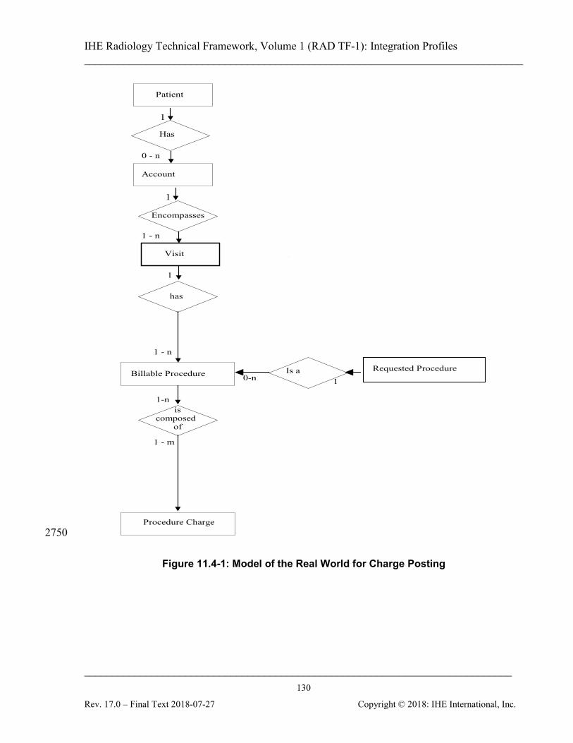
IHE Radiology Technical Framework, Volume 1 (RAD TF-1): Integration Profiles ______________________________________________________________________________
____________________________________________________________________________ 130
Rev. 17.0 – Final Text 2018-07-27 Copyright © 2018: IHE International, Inc.
Billable Procedure
is composed
of
has
1 - n
1-n
1 - m
Procedure Charge
Patient
Visit
Has
Account 1
1
1 - n
0 - n
Is a 1
Requested Procedure 0-n
Encompasses
1
2750
Figure 11.4-1: Model of the Real World for Charge Posting
IHE Radiology Technical Framework, Volume 1 (RAD TF-1): Integration Profiles ______________________________________________________________________________
____________________________________________________________________________ 131
Rev. 17.0 – Final Text 2018-07-27 Copyright © 2018: IHE International, Inc.
12 Post-Processing Workflow (PWF) IMPORTANT NOTE: As of June 2012, IHE introduces a new Trial Implementation Profile: Post-Acquisition Workflow (PAWF). The use cases addressed are largely the same as PWF, 2755 but the underlying mechanisms are improved. The PWF Profile documented in this section has been deprecated by the Radiology Domain and is now replaced by PAWF. When the PAWF Profile becomes Final Text, the contents of this section will be removed. In the interim, new implementations should be based on PAWF, found at http://www.ihe.net/Technical_Frameworks/#radiology 2760 The Post-Processing Workflow Integration Profile addresses the need to schedule and track the status of the typical post-processing workflow steps, such as Computer Aided Detection or Image Processing. Worklists for each of these tasks are generated and can be queried, workitems can be selected and the resulting status returned from the system performing the work to the system managing the work. Typically the workitems will involve the creation of objects such as 2765 images and evidence documents. The created images and evidence documents contain the necessary references for maintaining continuity of order information. The Post-Processing Workflow Integration Profile is a continuation of the Scheduled Workflow Integration Profile.
12.1 Actors/Transactions 2770
Figure 12.1-1 shows the actors directly involved in the Post-Processing Workflow Integration Profile and the relevant transactions between them. The italicized transactions represent a “generic” set of query/ retrieve transactions. The specific transactions required are dependent on which specific content profile(s) are supported by the Image Display and Image Manager/ Image Archive Actors. 2775
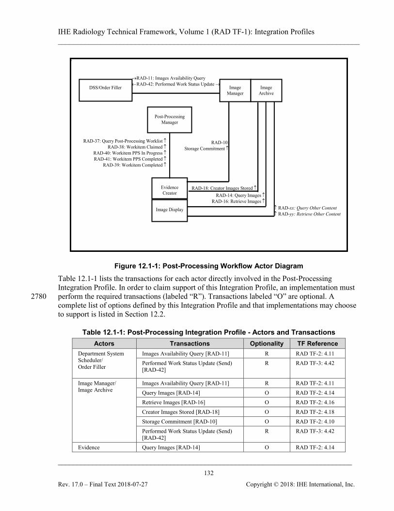
IHE Radiology Technical Framework, Volume 1 (RAD TF-1): Integration Profiles ______________________________________________________________________________
____________________________________________________________________________ 132
Rev. 17.0 – Final Text 2018-07-27 Copyright © 2018: IHE International, Inc.
v
→RAD-11: Images Availability Query ←RAD-42: Performed Work Status Update → Image
Manager Image
Archive DSS/Order Filler
Post-Processing Manager
↑ RAD-xx: Query Other Content ↑ RAD-yy: Retrieve Other Content
Image Display
Evidence Creator
RAD-37: Query Post-Processing Worklist ↑ RAD-38: Workitem Claimed ↑
RAD-40: Workitem PPS In Progress ↑ RAD-41: Workitem PPS Completed ↑
RAD-39: Workitem Completed ↑
RAD-18: Creator Images Stored ↑ RAD-14: Query Images ↑
RAD-16: Retrieve Images ↑
RAD-10: Storage Commitment ↑
Figure 12.1-1: Post-Processing Workflow Actor Diagram Table 12.1-1 lists the transactions for each actor directly involved in the Post-Processing Integration Profile. In order to claim support of this Integration Profile, an implementation must perform the required transactions (labeled “R”). Transactions labeled “O” are optional. A 2780 complete list of options defined by this Integration Profile and that implementations may choose to support is listed in Section 12.2.
Table 12.1-1: Post-Processing Integration Profile - Actors and Transactions Actors Transactions Optionality TF Reference
Department System Scheduler/ Order Filler
Images Availability Query [RAD-11] R RAD TF-2: 4.11 Performed Work Status Update (Send) [RAD-42]
R RAD TF-3: 4.42
Image Manager/ Image Archive
Images Availability Query [RAD-11] R RAD TF-2: 4.11 Query Images [RAD-14] O RAD TF-2: 4.14 Retrieve Images [RAD-16] O RAD TF-2: 4.16 Creator Images Stored [RAD-18] O RAD TF-2: 4.18 Storage Commitment [RAD-10] O RAD TF-2: 4.10 Performed Work Status Update (Send) [RAD-42]
R RAD TF-3: 4.42
Evidence Query Images [RAD-14] O RAD TF-2: 4.14
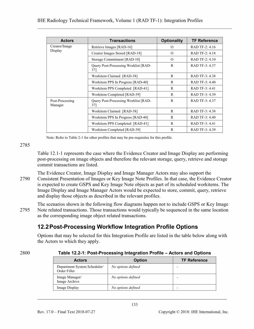
IHE Radiology Technical Framework, Volume 1 (RAD TF-1): Integration Profiles ______________________________________________________________________________
____________________________________________________________________________ 133
Rev. 17.0 – Final Text 2018-07-27 Copyright © 2018: IHE International, Inc.
Actors Transactions Optionality TF Reference Creator/Image Display
Retrieve Images [RAD-16] O RAD TF-2: 4.16 Creator Images Stored [RAD-18] O RAD TF-2: 4.18 Storage Commitment [RAD-10] O RAD TF-2: 4.10 Query Post-Processing Worklist [RAD-37]
R RAD TF-3: 4.37
Workitem Claimed [RAD-38] R RAD TF-3: 4.38 Workitem PPS In Progress [RAD-40] R RAD TF-3: 4.40 Workitem PPS Completed [RAD-41] R RAD TF-3: 4.41 Workitem Completed [RAD-39] R RAD TF-3: 4.39
Post-Processing Manager
Query Post-Processing Worklist [RAD-37]
R RAD TF-3: 4.37
Workitem Claimed [RAD-38] R RAD TF-3: 4.38 Workitem PPS In Progress [RAD-40] R RAD TF-3: 4.40 Workitem PPS Completed [RAD-41] R RAD TF-3: 4.41 Workitem Completed [RAD-39] R RAD TF-3: 4.39
Note: Refer to Table 2-1 for other profiles that may be pre-requisites for this profile.
2785 Table 12.1-1 represents the case where the Evidence Creator and Image Display are performing post-processing on image objects and therefore the relevant storage, query, retrieve and storage commit transactions are listed. The Evidence Creator, Image Display and Image Manager Actors may also support the Consistent Presentation of Images or Key Image Note Profiles. In that case, the Evidence Creator 2790 is expected to create GSPS and Key Image Note objects as part of its scheduled workitems. The Image Display and Image Manager Actors would be expected to store, commit, query, retrieve and display those objects as described in the relevant profiles. The scenarios shown in the following flow diagrams happen not to include GSPS or Key Image Note related transactions. Those transactions would typically be sequenced in the same location 2795 as the corresponding image object related transactions.
12.2 Post-Processing Workflow Integration Profile Options Options that may be selected for this Integration Profile are listed in the table below along with the Actors to which they apply.
Table 12.2-1: Post-Processing Integration Profile – Actors and Options 2800 Actors Option TF Reference
Department System Scheduler/ Order Filler
No options defined -
Image Manager/ Image Archive
No options defined -
Image Display No options defined -
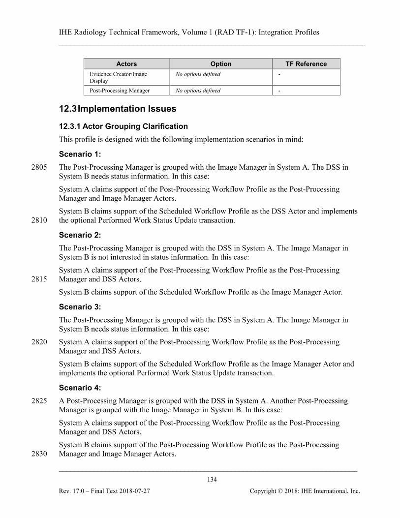
IHE Radiology Technical Framework, Volume 1 (RAD TF-1): Integration Profiles ______________________________________________________________________________
____________________________________________________________________________ 134
Rev. 17.0 – Final Text 2018-07-27 Copyright © 2018: IHE International, Inc.
Actors Option TF Reference Evidence Creator/Image Display
No options defined -
Post-Processing Manager No options defined -
12.3 Implementation Issues
12.3.1 Actor Grouping Clarification This profile is designed with the following implementation scenarios in mind:
Scenario 1: The Post-Processing Manager is grouped with the Image Manager in System A. The DSS in 2805 System B needs status information. In this case: System A claims support of the Post-Processing Workflow Profile as the Post-Processing Manager and Image Manager Actors. System B claims support of the Scheduled Workflow Profile as the DSS Actor and implements the optional Performed Work Status Update transaction. 2810
Scenario 2: The Post-Processing Manager is grouped with the DSS in System A. The Image Manager in System B is not interested in status information. In this case: System A claims support of the Post-Processing Workflow Profile as the Post-Processing Manager and DSS Actors. 2815 System B claims support of the Scheduled Workflow Profile as the Image Manager Actor.
Scenario 3: The Post-Processing Manager is grouped with the DSS in System A. The Image Manager in System B needs status information. In this case: System A claims support of the Post-Processing Workflow Profile as the Post-Processing 2820 Manager and DSS Actors. System B claims support of the Scheduled Workflow Profile as the Image Manager Actor and implements the optional Performed Work Status Update transaction.
Scenario 4: A Post-Processing Manager is grouped with the DSS in System A. Another Post-Processing 2825 Manager is grouped with the Image Manager in System B. In this case: System A claims support of the Post-Processing Workflow Profile as the Post-Processing Manager and DSS Actors. System B claims support of the Post-Processing Workflow Profile as the Post-Processing Manager and Image Manager Actors. 2830

IHE Radiology Technical Framework, Volume 1 (RAD TF-1): Integration Profiles ______________________________________________________________________________
____________________________________________________________________________ 135
Rev. 17.0 – Final Text 2018-07-27 Copyright © 2018: IHE International, Inc.
This leaves the site with the decision of how to reconcile control of the post-processing workflow. There are two approaches. Any system implementing the Post-Processing Manager shall be able to disable this functionality through configuration. In the first approach, the site selects one of the two systems to be the Post-Processing Manager 2835 for the Post-Processing workflow by configuring the other to disable its workflow management functionality. In the second approach, the site may configure one Post-Processing Manager to start Post-Processing worklists for one set of procedure codes and configure the second Post-Processing Manager to start Post-Processing worklists for a complementary set of procedure codes. Making 2840 sure that the procedure code sets are non-overlapping and complementary is a configuration responsibility of the site.
12.3.2 Input Availability In case of being grouped with the Image Manager, the Post-Processing Manager will have some internal logic to determine when images available are sufficient for the Post-Processing 2845 workflow to begin. In some cases, it may not be necessary for a post-processing to be performed. Generally these decisions are based on the procedure code of the requested procedure. In case of being grouped with the Department System Scheduler, the Post-Processing Manager uses the Image Availability transaction to know when images are available in the Image Archive for query. The image set needed for the Post-Processing workitem might or might not include all 2850 the instances the Post-Processing Manager has been notified about via previous MPPS or/and GP-PPS messages related to a requested procedure. Based on the received information and its internal logic the Post-Processing Manager decides which data the Post-Processing workitem input consists of. Generally, the Post-Processing Manager will create a workitem in the Post-Processing worklist 2855 when the required images are available, although it may create the workitem before that with an empty or incomplete Input Information Sequence and the Input Availability Flag set to PARTIAL, until the images are available in the Image Archive. The Post-Processing Manager and Post-Processing Client (Evidence Creator) must be prepared to handle workitems with PARTIAL image availability in a stable fashion. 2860 The Post-Processing Client may elect not to present workitems with PARTIAL status to the user for selection until their status later changes to COMPLETE. If the Post-Processing Client chooses to let the user select and start work on those items, then the Post-Processing Client is responsible for monitoring the post-processing worklist and make sure the user/application receives the full data when it is available. 2865 Similarly the Post-Processing Manager may choose to leave workitems with PARTIAL status out of provided worklists until the status is COMPLETE. If the Post-Processing Manager decides to provide PARTIAL workitems in the worklists, then it may be expected to check image
IHE Radiology Technical Framework, Volume 1 (RAD TF-1): Integration Profiles ______________________________________________________________________________
____________________________________________________________________________ 136
Rev. 17.0 – Final Text 2018-07-27 Copyright © 2018: IHE International, Inc.
availability and provide updated post-processing worklist replies to queries from the Post-Processing Client for workitems the client claims. 2870
12.3.3 Evidence Creators in Scheduled Workflow vs. Post-Processing Workflow An Evidence Creator that supports the Post-Processing Workflow Profile shall use mechanisms defined in this profile, i.e., General Purpose Performed Procedure Step, for all post-processing tasks including unscheduled tasks. Evidence Creators that only support the Scheduled Workflow Profile may continue to use the 2875 Modality Performed Procedure Step transactions to communicate tasks performed as described in the Scheduled Workflow Profile.
12.4 Post-Processing Process Flow The following are some possible post-processing use cases.
12.4.1 Computer Aided Detection Use Case 2880 A modality procedure (e.g., a mammography screening exam or a lung CT) is to be acquired and CAD processing is to be performed on the images. The images and CAD processing results will be interpreted together on a review workstation by the reading physician. The specific actors in this case are Acquisition Modality (digital mammography or CT acquisition system), Evidence Creator/Image Display (CAD processing system), Department 2885 System Scheduler, Image Manager/Image Archive, Post-Processing Manager, and Image Display (review workstation). The Post-Processing Manager is grouped with either the Department System Scheduler or Image Manager and is responsible for providing work to the Evidence Creator. The DICOM Standard services used are Storage of Images (Digital Mammography X-ray or CT), Query/Retrieve, 2890 General Purpose Worklist, and Storage of Structured Reports (e.g., Mammography CAD or Chest CAD). When MPPS Complete has been received and the acquired images are available on the Image Archive, the Post-Processing Manager would add a CAD workitem to the worklist. The CAD processing system would query the worklist, claim the workitem and based on the contained 2895 references, retrieve the images from the Image Manager and perform the scheduled CAD processing, reporting the status back to the Post-Processing Manager (including references to result objects created). The generated Evidence documents (CAD processing results) are stored as DICOM Structured Reports (e.g., Mammography CAD or Chest CAD). The Evidence Document includes references to the images that were analyzed (typically for 2900 mammography screening, the MLO and CC views of the left and right breasts), a summary of the algorithms that were executed, including algorithm identification, whether they succeeded or failed, and the findings detected by the algorithms. For example, CAD processing for mammography or lung studies may include identification of the locations of things like suspected densities (masses) and micro-calcifications on the images. 2905
IHE Radiology Technical Framework, Volume 1 (RAD TF-1): Integration Profiles ______________________________________________________________________________
____________________________________________________________________________ 137
Rev. 17.0 – Final Text 2018-07-27 Copyright © 2018: IHE International, Inc.
Although in this case, the Evidence Creator does not actually create images, just an Evidence Document object (e.g., a CAD object), it is also possible that if the images were enhanced during processing (e.g., a filtered image), new versions of the image might also be stored to the Image Manager. At the end, the Post-Processing Manager is notified with a GP-SPS update that the scheduled step is complete. 2910 The images and evidence documents are then available for retrieval by the Image Display Actor on a Review/Reporting system where they can be reviewed by a reading physician and a proper diagnostic report generated. In this way, the profile complements the Simple Image and Numeric Report Profile.
12.4.2 3D Reconstruction Use Case 2915 A modality procedure (e.g., a standard CT lumbar spine exam) is to be acquired and reconstructed and the results sent to a 3D post-processing application where Multi-Planar Reconstruction (MPR) is performed to get coronal images of the lumbar spine. The originally created axial images and the new coronal images are interpreted together, either at the modality or on a review station. 2920 The specific actors in this case are the Acquisition Modality (e.g., a CT system), Image Display/Evidence Creator (3D workstation), Department System Scheduler, Image Manager/Image Archive, Post-Processing Manager, and Image Display (review workstation). The Post-Processing Manager is grouped with either the Department System Scheduler or Image Manager and is responsible for providing work to the Evidence Creator. The DICOM Standard 2925 services used are Storage of Images (CT), Query/Retrieve, and General Purpose Worklist. When MPPS Complete has been received and the acquired images are available on the Image Archive, the Post-Processing Manager would add a post-processing workitem (GP-SPS) to the worklist. The 3D-processing system would query the worklist, claim the workitem and based on the contained references, retrieve the images from the Image Manager and perform the scheduled 2930 MPR processing, reporting the status back to the Post-Processing Manager (including references to result objects created). The MPR result images are stored as DICOM Images (CT). At the end, the Post-Processing Manager is notified with a GP-SPS update that the scheduled step is complete. The images are then available for retrieval by the Image Display Actor on a review/reporting 2935 system.
12.4.3 Post-Processing Process Flow Diagrams The following scenario illustrates a case where an image processing task is performed on acquired images and then a subsequent CAD step is performed on the processed images. The Transaction Summary is depicted for two scenarios: 2940
• The Post-Processing Manager is grouped with the Department System Scheduler
• The Post-Processing Manager is grouped with the Image Manager

IHE Radiology Technical Framework, Volume 1 (RAD TF-1): Integration Profiles ______________________________________________________________________________
____________________________________________________________________________ 138
Rev. 17.0 – Final Text 2018-07-27 Copyright © 2018: IHE International, Inc.
The Performed Work Status Update (Started) message must be sent sometime after the Workitem Claimed transaction but at the latest, when the first GP-PPS In Progress is received. In this scenario it is shown right after the Workitem Claimed. Also, it is conceivable that in some 2945 scenarios, the processing workstation has loaded potentially useful studies/images prior to claiming the workitem or maybe even before getting the worklist.
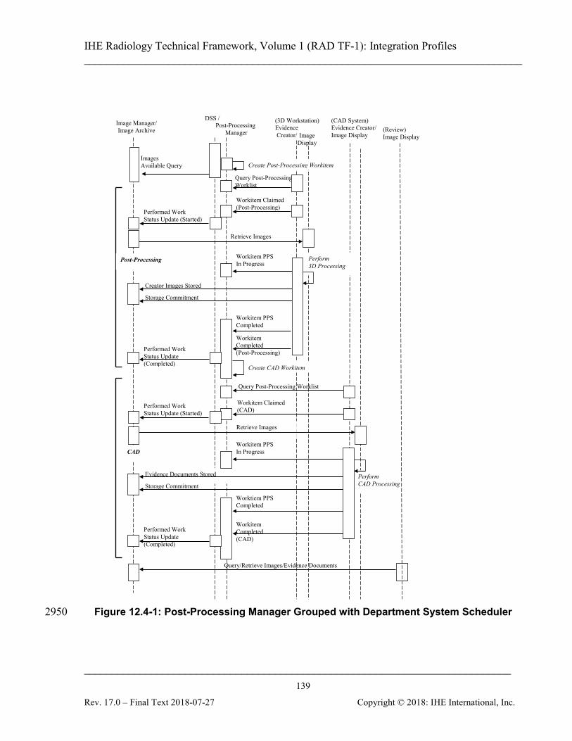
IHE Radiology Technical Framework, Volume 1 (RAD TF-1): Integration Profiles ______________________________________________________________________________
____________________________________________________________________________ 139
Rev. 17.0 – Final Text 2018-07-27 Copyright © 2018: IHE International, Inc.
Figure 12.4-1: Post-Processing Manager Grouped with Department System Scheduler 2950
Query/Retrieve Images/Evidence Documents
Creator Images Stored
Image Manager/ Image Archive
DSS /
Image Display
Query Post-Processing Worklist
(3D Workstation) Evidence Creator/
Retrieve Images
Workitem PPS In Progress
Workitem PPS Completed Workitem Completed (Post-Processing)
Perform 3D Processing
Workitem Claimed (Post-Processing)
(CAD System) Evidence Creator/ Image Display
(Review) Image Display
Query Post-Processing Worklist
Post-Processing Manager
Workitem Claimed (CAD)
Performed Work Status Update (Started)
Post-Processing
CAD
Images Available Query
Performed Work Status Update (Completed) Create CAD Workitem
Create Post-Processing Workitem
Retrieve Images
Evidence Documents Stored
Workitem PPS In Progress
Worktiem PPS Completed
Workitem Completed (CAD)
Perform CAD Processing
Performed Work Status Update (Completed)
Performed Work Status Update (Started)
Storage Commitment
Storage Commitment

IHE Radiology Technical Framework, Volume 1 (RAD TF-1): Integration Profiles ______________________________________________________________________________
____________________________________________________________________________ 140
Rev. 17.0 – Final Text 2018-07-27 Copyright © 2018: IHE International, Inc.
Evidence Document Stored
Images Available
Query/Retrieve Images/Evidence Documents
Creator Images Stored
Image Manager/ Image Archive DSS
Image Display
Query Post-Processing Worklist
(3D Workstation) Evidence Creator/
Retrieve Images
Workitem PPS In Progress
Workitem PPS Completed Workitem Completed (Post-Processing)
Perform 3D Processing
Workitem Claimed (Post-Processing)
(CAD System) Evidence Creator/ Image Display
(Review) Image Display
Query Post-Processing Worklist
Post-Processing Manager
Workitem Claimed (CAD)
Performed Work Status Update (Started)
Post-Processing
CAD
Performed Work Status Update (Completed) Create CAD Workitem
Create Post-Processing Workitem
Retrieve Images
Workitem PPS In Progress
Workitem PPS Completed Workitem Completed (CAD)
Perform CAD Processing
Performed Work Status Update (Completed)
Performed Work Status Update (Started)
Storage Commitment
Storage Commitment
Figure 12.4-2: Post-Processing Manager Grouped with Image Manager
IHE Radiology Technical Framework, Volume 1 (RAD TF-1): Integration Profiles ______________________________________________________________________________
____________________________________________________________________________ 141
Rev. 17.0 – Final Text 2018-07-27 Copyright © 2018: IHE International, Inc.
13 Reporting Workflow (RWF) The Reporting Workflow Profile addresses the need to schedule and track the status of the various reporting tasks. Reporting tasks include interpretation, dictation, transcription, 2955 verification, comparison, revision, and coding. Workitems for each of these tasks are generated and can be queried from worklists. Workitems can be claimed. The resulting intermediate and final statuses can be returned from the system performing the work to the system managing the work. The system managing the work also makes the status available for other interested systems in the enterprise. 2960 The output of the Reporting Workflow Profile is defined to be information encoded as DICOM SR objects. The details for creation, storage, query/ retrieve and encoding are described by the Simple Image and Numeric Report (SINR) Profile (see Section 9). The Reporting Workflow Integration Profile is a continuation of the Scheduled Workflow Integration Profile. 2965
13.1 Actors/Transactions Figure 13.1-1 shows the actors directly involved in the Reporting Workflow Integration Profile and the relevant transactions between them. Other actors that may be indirectly involved due to their participation in the Scheduled Workflow, etc. are not necessarily shown. Image Display can participate in this profile if it is grouped with a Report Creator. 2970

IHE Radiology Technical Framework, Volume 1 (RAD TF-1): Integration Profiles ______________________________________________________________________________
____________________________________________________________________________ 142
Rev. 17.0 – Final Text 2018-07-27 Copyright © 2018: IHE International, Inc.
← RAD-46: Query Reporting Worklist ← RAD-38: Workitem Claimed ← RAD-41: Workitem Completed ← RAD-39: Workitem PPS in Progress ← RAD-40: Workitem PPS Completed
Performed Procedure
Step Manager
Image Manager
Image Archive
RAD-7: Modality PS Completed↑
DSS/ Order Filler
Report Manager
Report Creator
↓ RAD-4: Procedure Scheduled ↓ RAD-13: Procedure Update ↑ RAD-42: Performed Work Status Update
← RAD-11: Image Availability Query
Report Reader
Figure 13.1-1: Reporting Workflow Actor Diagram
Table 13.1-1 lists the transactions for each actor directly involved in the Reporting Workflow Integration Profile. In order to claim support of this Integration Profile, an implementation must 2975 perform the required transactions (labeled “R”). Transactions labeled “O” are optional. A complete list of options defined by this Integration Profile and that implementations may choose to support is listed in Section 13.2.
Table 13.1-1: Reporting Workflow Integration Profile - Actors and Transactions Actors Transactions Optionalit
y TF Reference
Department System Scheduler/ Order Filler
Procedure Scheduled [RAD-4] R RAD TF-2: 4.4 Procedure Update [RAD-13] R RAD TF-2: 4.13 Performed Work Status Update (Receive) [RAD-42]
R RAD TF-3: 4.42
Image Manager/ Image Archive
Images Availability Query [RAD-11] R RAD TF-2: 4.11 Query Images [RAD-14] R RAD TF-2: 4.14 Retrieve Images [RAD-16] R RAD TF-2: 4.16
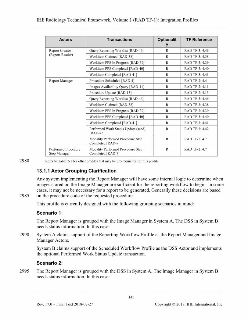
IHE Radiology Technical Framework, Volume 1 (RAD TF-1): Integration Profiles ______________________________________________________________________________
____________________________________________________________________________ 143
Rev. 17.0 – Final Text 2018-07-27 Copyright © 2018: IHE International, Inc.
Actors Transactions Optionality
TF Reference
Report Creator (Report Reader)
Query Reporting Worklist [RAD-46] R RAD TF-3: 4.46 Workitem Claimed [RAD-38] R RAD TF-3: 4.38 Workitem PPS In Progress [RAD-39] R RAD TF-3: 4.39 Workitem PPS Completed [RAD-40] R RAD TF-3: 4.40 Workitem Completed [RAD-41] R RAD TF-3: 4.41
Report Manager Procedure Scheduled [RAD-4] R RAD TF-2: 4.4 Images Availability Query [RAD-11] R RAD TF-2: 4.11 Procedure Update [RAD-13] R RAD TF-2: 4.13 Query Reporting Worklist [RAD-46] R RAD TF-3: 4.46 Workitem Claimed [RAD-38] R RAD TF-3: 4.38 Workitem PPS In Progress [RAD-39] R RAD TF-3: 4.39 Workitem PPS Completed [RAD-40] R RAD TF-3: 4.40 Workitem Completed [RAD-41] R RAD TF-3: 4.41 Performed Work Status Update (send) [RAD-42]
R RAD TF-3: 4.42
Modality Performed Procedure Step Completed [RAD-7]
R RAD TF-2: 4.7
Performed Procedure Step Manager
Modality Performed Procedure Step Completed [RAD-7]
R RAD TF-2: 4.7
Refer to Table 2-1 for other profiles that may be pre-requisites for this profile. 2980
13.1.1 Actor Grouping Clarification Any system implementing the Report Manager will have some internal logic to determine when images stored on the Image Manager are sufficient for the reporting workflow to begin. In some cases, it may not be necessary for a report to be generated. Generally these decisions are based on the procedure code of the requested procedure. 2985 This profile is currently designed with the following grouping scenarios in mind:
Scenario 1: The Report Manager is grouped with the Image Manager in System A. The DSS in System B needs status information. In this case: System A claims support of the Reporting Workflow Profile as the Report Manager and Image 2990 Manager Actors. System B claims support of the Scheduled Workflow Profile as the DSS Actor and implements the optional Performed Work Status Update transaction.
Scenario 2: The Report Manager is grouped with the DSS in System A. The Image Manager in System B 2995 needs status information. In this case:
IHE Radiology Technical Framework, Volume 1 (RAD TF-1): Integration Profiles ______________________________________________________________________________
____________________________________________________________________________ 144
Rev. 17.0 – Final Text 2018-07-27 Copyright © 2018: IHE International, Inc.
System A claims support of the Reporting Workflow Profile as the Report Manager and DSS Actors. System B claims support of the Scheduled Workflow Profile as the Image Manager Actor.
Scenario 3: 3000 A Report Manager is implemented on a system A and is grouped with neither the DSS nor the Image Manager. The DSS in system B needs status information. The Image Manager in System C might or might not need the status information. In this case: System A claims support of the Reporting Workflow Profile as the Report Manager Actor. System B claims support of the Scheduled Workflow Profile as the DSS Actor and implements 3005 the Performed Work Status Update transaction. System C claims support of the Scheduled Workflow Profile as the Image Manager Actor and may implement the optional Performed Work Status Update transaction if the needed.
13.1.2 Input Availability The Report Manager uses the Images Availability Query transaction to know when images are 3010 available in the Image Archive for query. The image set relevant for the reporting workflow might or might not include all the instances the Report Manager has been notified about via previous MPPS or/and GP-PPS messages related to a requested procedure. Based on the received information and its internal logic the Report Manager decides which data the reporting workitem input consists of. 3015 Generally, the Reporting Manager will create a workitem in the reporting worklist when the required images are available, although it may create the workitem before that with an incomplete Input Information Sequence and the Input Availability Flag set to PARTIAL. The Reporting Manager and Report Creator must be able to handle workitems with PARTIAL image availability in a stable way. The Report Creator may not display workitems with PARTIAL 3020 status to the user for selection until their status later changes to COMPLETE. If the Report Creator allows the user to select and start work on items with partially available input, then the Report Creator is responsible for monitoring the reporting worklist and make sure the user receives the full data when it is available. Similarly the Report Manager may choose to leave workitems with PARTIAL status out of the 3025 provided worklist until the status is COMPLETE. If the Report Manager provides workitems with partially available input data in the worklist, then a later check of the image availability and update of the workitem in the worklist may be expected even for workitems that have been already claimed.
13.2 Reporting Workflow Integration Profile Options 3030
Options that may be selected for this Integration Profile are listed in the Table 13.2-1 along with the Actors to which they apply. Dependencies between options when applicable are specified in notes.
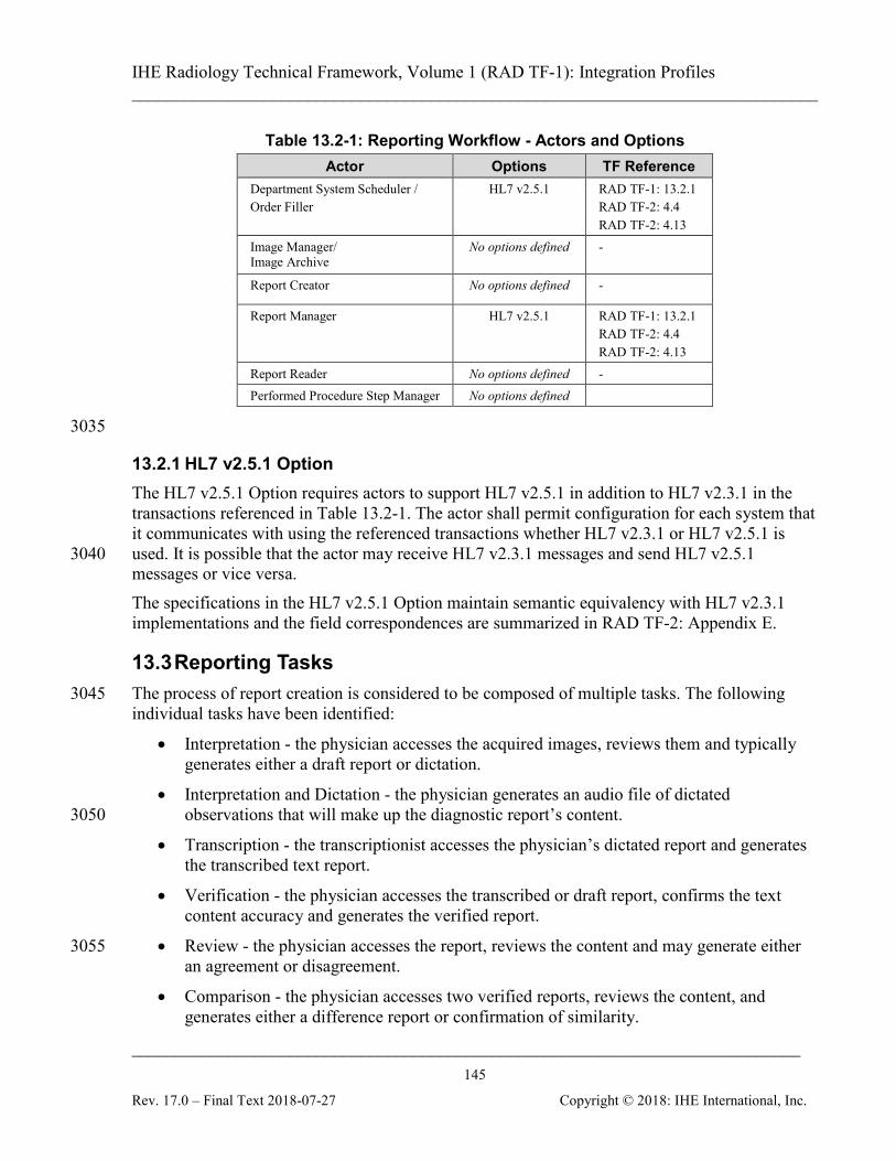
IHE Radiology Technical Framework, Volume 1 (RAD TF-1): Integration Profiles ______________________________________________________________________________
____________________________________________________________________________ 145
Rev. 17.0 – Final Text 2018-07-27 Copyright © 2018: IHE International, Inc.
Table 13.2-1: Reporting Workflow - Actors and Options Actor Options TF Reference
Department System Scheduler / Order Filler
HL7 v2.5.1 RAD TF-1: 13.2.1 RAD TF-2: 4.4 RAD TF-2: 4.13
Image Manager/ Image Archive
No options defined -
Report Creator No options defined -
Report Manager HL7 v2.5.1 RAD TF-1: 13.2.1 RAD TF-2: 4.4 RAD TF-2: 4.13
Report Reader No options defined - Performed Procedure Step Manager No options defined
3035
13.2.1 HL7 v2.5.1 Option The HL7 v2.5.1 Option requires actors to support HL7 v2.5.1 in addition to HL7 v2.3.1 in the transactions referenced in Table 13.2-1. The actor shall permit configuration for each system that it communicates with using the referenced transactions whether HL7 v2.3.1 or HL7 v2.5.1 is used. It is possible that the actor may receive HL7 v2.3.1 messages and send HL7 v2.5.1 3040 messages or vice versa. The specifications in the HL7 v2.5.1 Option maintain semantic equivalency with HL7 v2.3.1 implementations and the field correspondences are summarized in RAD TF-2: Appendix E.
13.3 Reporting Tasks The process of report creation is considered to be composed of multiple tasks. The following 3045 individual tasks have been identified:
• Interpretation - the physician accesses the acquired images, reviews them and typically generates either a draft report or dictation.
• Interpretation and Dictation - the physician generates an audio file of dictated observations that will make up the diagnostic report’s content. 3050
• Transcription - the transcriptionist accesses the physician’s dictated report and generates the transcribed text report.
• Verification - the physician accesses the transcribed or draft report, confirms the text content accuracy and generates the verified report.
• Review - the physician accesses the report, reviews the content and may generate either 3055 an agreement or disagreement.
• Comparison - the physician accesses two verified reports, reviews the content, and generates either a difference report or confirmation of similarity.
IHE Radiology Technical Framework, Volume 1 (RAD TF-1): Integration Profiles ______________________________________________________________________________
____________________________________________________________________________ 146
Rev. 17.0 – Final Text 2018-07-27 Copyright © 2018: IHE International, Inc.
• Coding - the coder accesses a draft or verified report, and assigns codes. Note: Verification is considered to be different from a signature, although it may trigger a signature. A signature has 3060
policies attached to it. It is not part of this Reporting Workflow profile.
In the report creation process, actors such as the report creator perform relevant workitems obtained by querying the relevant worklist. Depending on the capabilities of the system containing the Report Creator Actor and the permissions of the user, it may be possible to carry out several steps at once. For example, a 3065 speech recognition workstation may support interpretation, dictation and transcription all at once, and a senior physician may have authority to immediately verify the resulting report. In other situations or implementations, it may be necessary to perform the steps separately. The types and sequence of tasks may vary from site to site. A sequential process made up of an interpretation/dictation, a transcription and a verification task is very common, but can vary 3070 between institutions. The logic of determining what tasks to schedule and when to schedule them is the responsibility of the Report Manager and is not defined by IHE. Typically, this logic will involve completion of pre-requisite tasks and/or availability of needed input objects. Much of the needed information is available in the PPS Transactions from the Report Creators, Image Managers and other actors, 3075 in the Image Availability Transaction to the Image Manager, and in reports stored to the Report Manager. The logic of presenting a relevant list of workitems to the user is the responsibility of the Report Creator and is only partially defined by IHE in the Query Reporting Worklist transaction. Typically, this will involve filtering the available workitems based on the Scheduled Workitem 3080 Code (to find particular types of tasks), the Scheduled Human Performer (to find work for a particular person), the Scheduled Station Name (to find work for a particular workstation), Patient Name (to find work for a particular patient), Accession Number (to find work for a particular order), or Procedure Step Status (to find work in a particular state). A number of common workitem codes are listed in RAD TF-3: 4.46 - Query Reporting Worklist. 3085 Systems may allow sites to configure additional codes that reflect their local workflow practices and can be used by the Report Creators to filter workitems. As the Report Creator completes tasks, it reports performed workitem codes to the Report Manager. This is particularly important when the Report Creator performs additional tasks as it enables the Report Manager to modify the workflow. Further robustness and flexibility is 3090 provided by allowing the Report Creator to identify and suggest subsequent workitem codes in the General Purpose Performed Procedure Step Results Module, giving the Report Manager additional input to the logic it uses to select subsequent workflow steps in an adaptive manner. The following diagram (Figure 13.3-1, parts 1 & 2) gives an example of a full Reporting Workflow from scheduling of the initial Interpretation/Dictation task, to the final release of the 3095 verified report. Prior to the start of this, images and evidence documents would have been stored to the Image Manager and PPS transactions containing references to those objects sent to the Report Manager.
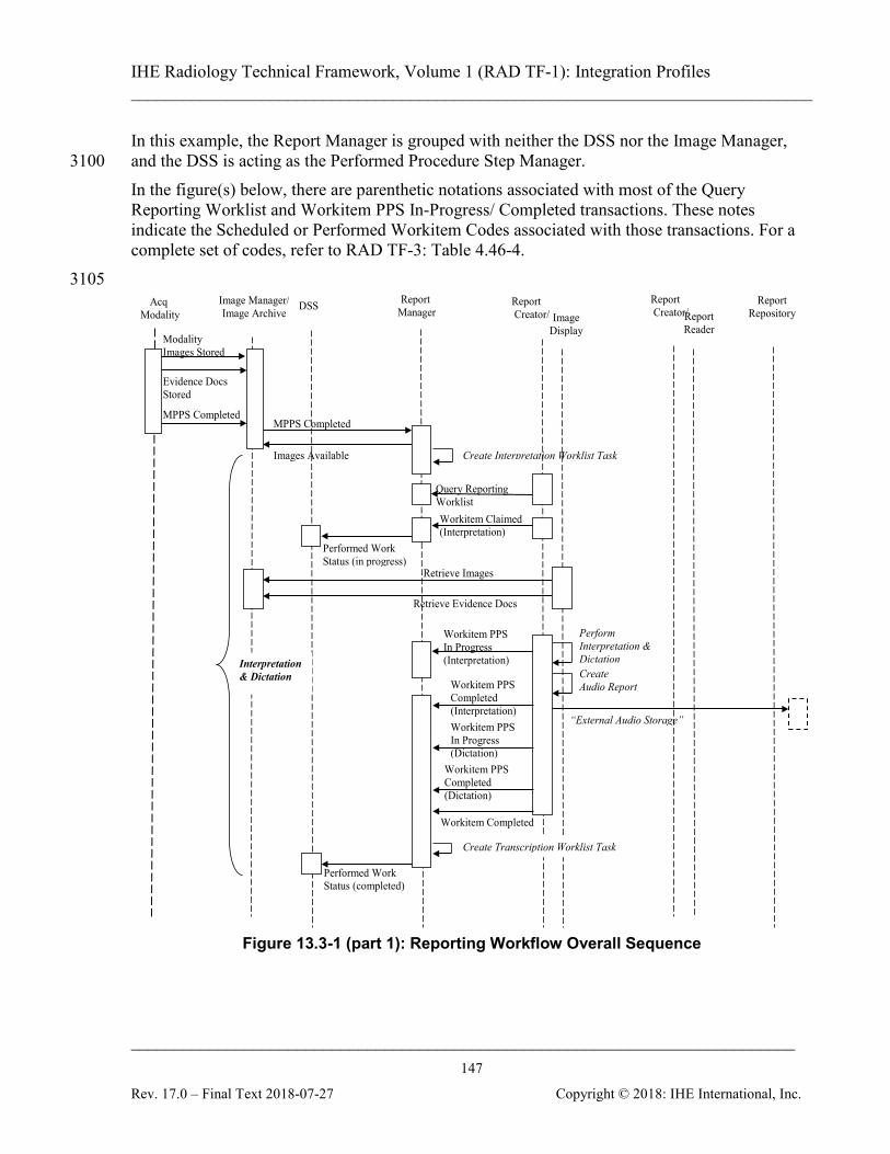
IHE Radiology Technical Framework, Volume 1 (RAD TF-1): Integration Profiles ______________________________________________________________________________
____________________________________________________________________________ 147
Rev. 17.0 – Final Text 2018-07-27 Copyright © 2018: IHE International, Inc.
In this example, the Report Manager is grouped with neither the DSS nor the Image Manager, and the DSS is acting as the Performed Procedure Step Manager. 3100 In the figure(s) below, there are parenthetic notations associated with most of the Query Reporting Worklist and Workitem PPS In-Progress/ Completed transactions. These notes indicate the Scheduled or Performed Workitem Codes associated with those transactions. For a complete set of codes, refer to RAD TF-3: Table 4.46-4. 3105
Evidence Docs Stored
Modality Images Stored
Create Interpretation Worklist Task
Image Manager/ Image Archive
DSS Image
Display
Query Reporting Worklist
MPPS Completed
Report Creator/
Retrieve Evidence Docs
Retrieve Images
Workitem PPS In Progress (Interpretation)
Report Repository
Perform Interpretation & Dictation
Workitem Claimed (Interpretation)
Create Audio Report
“External Audio Storage”
Report Creator/
Report Manager
Performed Work Status (in progress)
Report Reader
Images Available
Create Transcription Worklist Task
Workitem PPS Completed (Interpretation)
Workitem Completed
Performed Work Status (completed)
Interpretation & Dictation
Workitem PPS Completed (Dictation)
Acq Modality
MPPS Completed
Workitem PPS In Progress (Dictation)
Figure 13.3-1 (part 1): Reporting Workflow Overall Sequence

IHE Radiology Technical Framework, Volume 1 (RAD TF-1): Integration Profiles ______________________________________________________________________________
____________________________________________________________________________ 148
Rev. 17.0 – Final Text 2018-07-27 Copyright © 2018: IHE International, Inc.
Perform Transcription
Image Manager/ Image Archive DSS
Image Display
Report Creator/
Report Repository Report
Creator/
“Retrieve External Audio”
Report creation
Report Manager
Workitem Claimed (Transcription)
Workitem PPS In Progress (Transcription)
Report Submission
Workitem PPS Completed (Transcription) Workitem Completed
Report Reader
Transcription
Create Verification Worklist Task
Query Reporting Worklist (Transcription)
Performed Work Status (in progress)
Performed Work Status (completed)
Retrieve Reports
Image Manager/ Image Archive DSS
Image Display
Query Reporting Worklist
Report Creator/
Workitem PPS In Progress (Verification)
Workitem PPS Completed (Verification)
Workitem Completed
Report Repository
Workitem Claimed (Verification)
Report Creator/
Report Manager
Performed Work Status (in progress)
Report Reade
Performed Work Status (completed)
Report Submission Perform Verification
Report Issuing (Verified)
Retrieve Report (Preliminary)
Verification
Report Reader
Query Reports
Figure 13.3-1 (part 2): Reporting Workflow Overall Sequence 3110
IHE Radiology Technical Framework, Volume 1 (RAD TF-1): Integration Profiles ______________________________________________________________________________
____________________________________________________________________________ 149
Rev. 17.0 – Final Text 2018-07-27 Copyright © 2018: IHE International, Inc.
13.4 Diagnostic Reporting Use Cases This section describes diagnostic reporting creation uses cases. Each use case is a combination of one or many reporting tasks. These use cases do not cover all reporting use cases. However, their feasibility is demonstrated.
13.4.1 Use case 1: Predefined Report 3115 The primary user is the reading physician. When interpreting a study, the user chooses a report from a list of pre-configured draft reports and can edit the report’s content in order to customize it. This use case covers the situation where the user can use a predefined/ canned report (which is frequently the case when the results are normal), and has permission to verify the report. This use case finally results in: 3120
• multiple Performed Procedure Steps for each of the performed workitems Interpretation, Transcription and Report Verification, each having a corresponding code value in the Performed Workitem Code Sequence;
• a report which has been verified and is referenced in the output results status message;
• removing the workitem from the worklist, after the workitem status was set to completed. 3125
The basic flow is illustrated in Figure 13.4-1
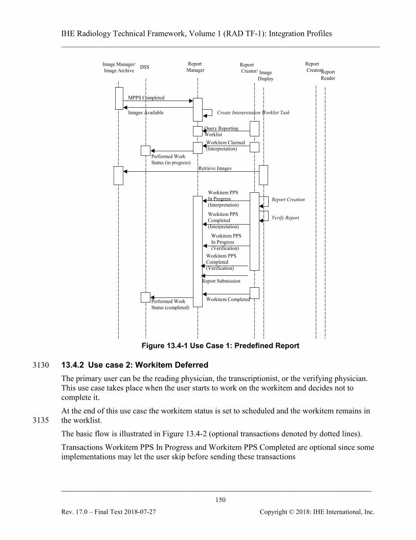
IHE Radiology Technical Framework, Volume 1 (RAD TF-1): Integration Profiles ______________________________________________________________________________
____________________________________________________________________________ 150
Rev. 17.0 – Final Text 2018-07-27 Copyright © 2018: IHE International, Inc.
Create Interpretation Worklist Task
Image Manager/ Image Archive DSS
Image Display
Query Reporting Worklist
MPPS Completed
Report Creator/
Retrieve Images
Workitem PPS In Progress (Interpretation)
Workitem PPS Completed (Interpretation)
Workitem Completed
Report Creation
Workitem Claimed (Interpretation)
Verify Report
Report Creator/
Report Manager
Performed Work Status (in progress)
Report Reader
Images Available
Performed Work Status (completed)
Workitem PPS Completed (Verification)
Report Submission
Workitem PPS In Progress (Verification)
Figure 13.4-1 Use Case 1: Predefined Report
13.4.2 Use case 2: Workitem Deferred 3130 The primary user can be the reading physician, the transcriptionist, or the verifying physician. This use case takes place when the user starts to work on the workitem and decides not to complete it. At the end of this use case the workitem status is set to scheduled and the workitem remains in the worklist. 3135 The basic flow is illustrated in Figure 13.4-2 (optional transactions denoted by dotted lines). Transactions Workitem PPS In Progress and Workitem PPS Completed are optional since some implementations may let the user skip before sending these transactions
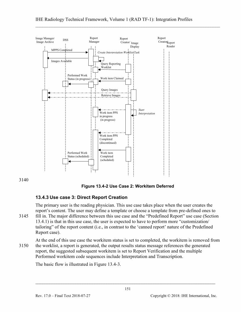
IHE Radiology Technical Framework, Volume 1 (RAD TF-1): Integration Profiles ______________________________________________________________________________
____________________________________________________________________________ 151
Rev. 17.0 – Final Text 2018-07-27 Copyright © 2018: IHE International, Inc.
Retrieve Images
Create Interpretation Worklist Task
Image Manager/ Image Archive DSS
Image Display
Query Reporting Worklist
MPPS Completed
Report Creator/
Query Images
Work item PPS in progress (in progress)
Work item PPS Completed (discontinued)
Work item Completed (scheduled)
Start Interpretation
Work item Claimed
Report Creator/
Report Manager
Performed Work Status (in progress)
Report Reader
Images Available
Performed Work Status (scheduled)
3140 Figure 13.4-2 Use Case 2: Workitem Deferred
13.4.3 Use case 3: Direct Report Creation The primary user is the reading physician. This use case takes place when the user creates the report’s content. The user may define a template or choose a template from pre-defined ones to fill in. The major difference between this use case and the “Predefined Report” use case (Section 3145 13.4.1) is that in this use case, the user is expected to have to perform more “customization/ tailoring” of the report content (i.e., in contrast to the ‘canned report’ nature of the Predefined Report case). At the end of this use case the workitem status is set to completed, the workitem is removed from the worklist, a report is generated, the output results status message references the generated 3150 report, the suggested subsequent workitem is set to Report Verification and the multiple Performed workitem code sequences include Interpretation and Transcription. The basic flow is illustrated in Figure 13.4-3.
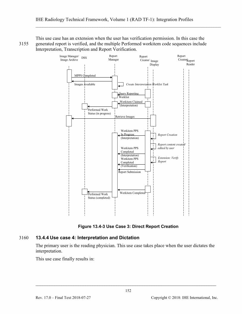
IHE Radiology Technical Framework, Volume 1 (RAD TF-1): Integration Profiles ______________________________________________________________________________
____________________________________________________________________________ 152
Rev. 17.0 – Final Text 2018-07-27 Copyright © 2018: IHE International, Inc.
This use case has an extension when the user has verification permission. In this case the generated report is verified, and the multiple Performed workitem code sequences include 3155 Interpretation, Transcription and Report Verification.
Create Interpretation Worklist Task
Image Manager/ Image Archive DSS
Image Display
Query Reporting Worklist
MPPS Completed
Report Creator/
Retrieve Images
Workitem PPS In Progress (Interpretation)
Workitem PPS Completed (Interpretation)
Workitem Completed
Report Creation
Workitem Claimed (Interpretation)
Extension: Verify Report
Report Creator/
Report Manager
Performed Work Status (in progress)
Report Reader
Images Available
Performed Work Status (completed)
Workitem PPS Completed (Verification)
Report Submission
Report content created/ edited by user
Figure 13.4-3 Use Case 3: Direct Report Creation
13.4.4 Use case 4: Interpretation and Dictation 3160 The primary user is the reading physician. This use case takes place when the user dictates the interpretation. This use case finally results in:
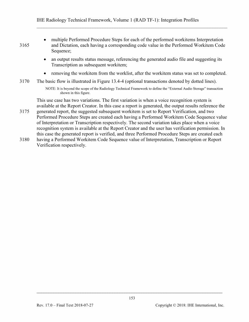
IHE Radiology Technical Framework, Volume 1 (RAD TF-1): Integration Profiles ______________________________________________________________________________
____________________________________________________________________________ 153
Rev. 17.0 – Final Text 2018-07-27 Copyright © 2018: IHE International, Inc.
• multiple Performed Procedure Steps for each of the performed workitems Interpretation and Dictation, each having a corresponding code value in the Performed Workitem Code 3165 Sequence;
• an output results status message, referencing the generated audio file and suggesting its Transcription as subsequent workitem;
• removing the workitem from the worklist, after the workitem status was set to completed. The basic flow is illustrated in Figure 13.4-4 (optional transactions denoted by dotted lines). 3170
NOTE: It is beyond the scope of the Radiology Technical Framework to define the “External Audio Storage” transaction shown in this figure.
This use case has two variations. The first variation is when a voice recognition system is available at the Report Creator. In this case a report is generated, the output results reference the generated report, the suggested subsequent workitem is set to Report Verification, and two 3175 Performed Procedure Steps are created each having a Performed Workitem Code Sequence value of Interpretation or Transcription respectively. The second variation takes place when a voice recognition system is available at the Report Creator and the user has verification permission. In this case the generated report is verified, and three Performed Procedure Steps are created each having a Performed Workitem Code Sequence value of Interpretation, Transcription or Report 3180 Verification respectively.
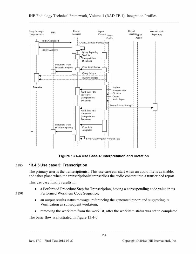
IHE Radiology Technical Framework, Volume 1 (RAD TF-1): Integration Profiles ______________________________________________________________________________
____________________________________________________________________________ 154
Rev. 17.0 – Final Text 2018-07-27 Copyright © 2018: IHE International, Inc.
Create Dictation Worklist Task
Image Manager/ Image Archive DSS
Image Display
Query Reporting Worklist (interpretation, Dictation)
MPPS Completed
Report Creator/
Query Images
Retrieve Images
Work item PPS in progress (interpretation, Dictation)
Work item PPS Completed (interpretation, Dictation)
Work item Completed
Perform Interpretation, Dictation
Work item Claimed
Create Audio Report
External Audio Repository
“External Audio Storage”
Report Creator/
Report Manager
Performed Work Status (in progress)
Report Reader
Images Available
Performed Work Status (completed)
Create Transcription Worklist Task
Dictation
Figure 13.4-4 Use Case 4: Interpretation and Dictation
13.4.5 Use case 5: Transcription 3185 The primary user is the transcriptionist. This use case can start when an audio file is available, and takes place when the transcriptionist transcribes the audio content into a transcribed report. This use case finally results in:
• a Performed Procedure Step for Transcription, having a corresponding code value in its Performed Workitem Code Sequence; 3190
• an output results status message, referencing the generated report and suggesting its Verification as subsequent workitem;
• removing the workitem from the worklist, after the workitem status was set to completed. The basic flow is illustrated in Figure 13.4-5.
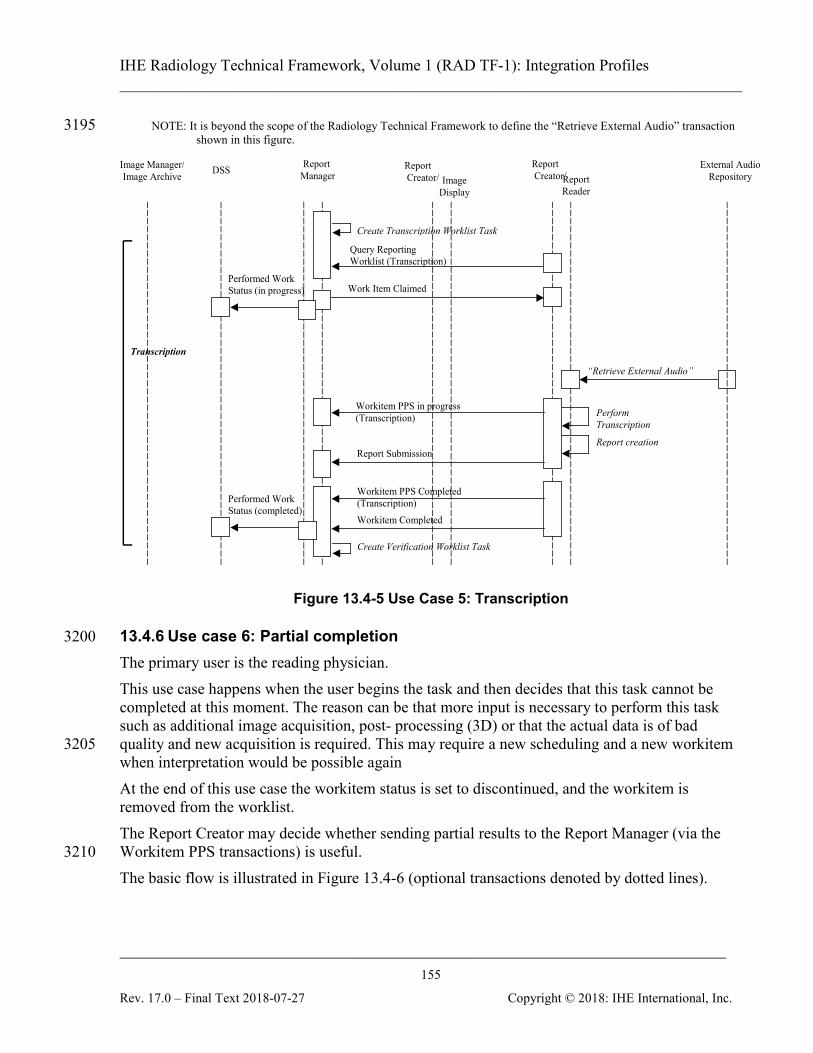
IHE Radiology Technical Framework, Volume 1 (RAD TF-1): Integration Profiles ______________________________________________________________________________
____________________________________________________________________________ 155
Rev. 17.0 – Final Text 2018-07-27 Copyright © 2018: IHE International, Inc.
NOTE: It is beyond the scope of the Radiology Technical Framework to define the “Retrieve External Audio” transaction 3195 shown in this figure.
Perform Transcription
Image Manager/ Image Archive DSS
Image Display
Report Creator/
External Audio Repository
Report Creator/
“Retrieve External Audio”
Report creation
Report Manager
Work Item Claimed
Workitem PPS in progress (Transcription)
Report Submission
Workitem PPS Completed (Transcription) Workitem Completed
Report Reader
Transcription
Create Transcription Worklist Task
Create Verification Worklist Task
Query Reporting Worklist (Transcription)
Performed Work Status (in progress)
Performed Work Status (completed)
Figure 13.4-5 Use Case 5: Transcription
13.4.6 Use case 6: Partial completion 3200 The primary user is the reading physician. This use case happens when the user begins the task and then decides that this task cannot be completed at this moment. The reason can be that more input is necessary to perform this task such as additional image acquisition, post- processing (3D) or that the actual data is of bad quality and new acquisition is required. This may require a new scheduling and a new workitem 3205 when interpretation would be possible again At the end of this use case the workitem status is set to discontinued, and the workitem is removed from the worklist. The Report Creator may decide whether sending partial results to the Report Manager (via the Workitem PPS transactions) is useful. 3210 The basic flow is illustrated in Figure 13.4-6 (optional transactions denoted by dotted lines).
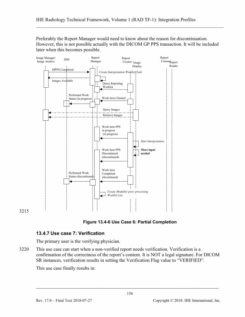
IHE Radiology Technical Framework, Volume 1 (RAD TF-1): Integration Profiles ______________________________________________________________________________
____________________________________________________________________________ 156
Rev. 17.0 – Final Text 2018-07-27 Copyright © 2018: IHE International, Inc.
Preferably the Report Manager would need to know about the reason for discontinuation. However, this is not possible actually with the DICOM GP PPS transaction. It will be included later when this becomes possible.
Create Interpretation Worklist Task
Image Manager/ Image Archive DSS
Image Display
Query Reporting Worklist
MPPS Completed
Report Creator/
Query Images
Retrieve Images
Work item PPS in progress (in progress)
Work item PPS Discontinued (discontinued)
Work item Completed (dicontinued)
Work item Claimed
Report Creator/
Report Manager
Performed Work Status (in progress)
Report Reader
Images Available
Performed Work Status (discontinued)
Start Interpretation
More input needed
Create Modality/ post- processing Worklist List
3215
Figure 13.4-6 Use Case 6: Partial Completion
13.4.7 Use case 7: Verification The primary user is the verifying physician. This use case can start when a non-verified report needs verification. Verification is a 3220 confirmation of the correctness of the report’s content. It is NOT a legal signature. For DICOM SR instances, verification results in setting the Verification Flag value to “VERIFIED”. This use case finally results in:
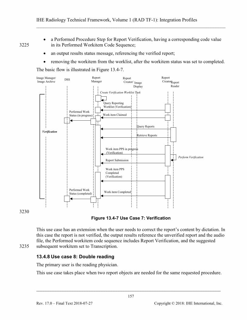
IHE Radiology Technical Framework, Volume 1 (RAD TF-1): Integration Profiles ______________________________________________________________________________
____________________________________________________________________________ 157
Rev. 17.0 – Final Text 2018-07-27 Copyright © 2018: IHE International, Inc.
• a Performed Procedure Step for Report Verification, having a corresponding code value in its Performed Workitem Code Sequence; 3225
• an output results status message, referencing the verified report;
• removing the workitem from the worklist, after the workitem status was set to completed. The basic flow is illustrated in Figure 13.4-7.
Create Verification Worklist Task
Image Manager/ Image Archive DSS
Image Display
Query Reporting Worklist (Verification)
Report Creator/
Work item PPS in progress (Verification)
Work item PPS Completed (Verification)
Work item Completed
Work item Claimed
Report Creator/
Report Manager
Performed Work Status (in progress)
Report Reader
Performed Work Status (completed)
Report Submission Perform Verification
Query Reports
Retrieve Reports Verification
3230 Figure 13.4-7 Use Case 7: Verification
This use case has an extension when the user needs to correct the report’s content by dictation. In this case the report is not verified, the output results reference the unverified report and the audio file, the Performed workitem code sequence includes Report Verification, and the suggested subsequent workitem set to Transcription. 3235
13.4.8 Use case 8: Double reading The primary user is the reading physician. This use case takes place when two report objects are needed for the same requested procedure.
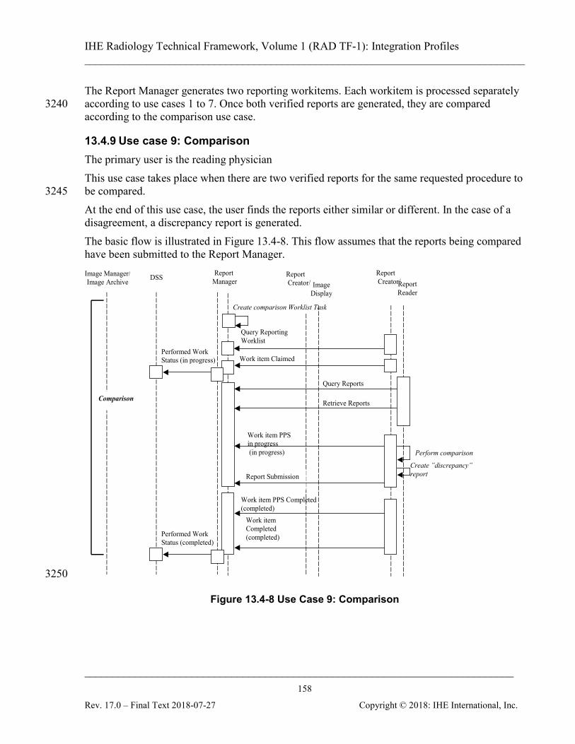
IHE Radiology Technical Framework, Volume 1 (RAD TF-1): Integration Profiles ______________________________________________________________________________
____________________________________________________________________________ 158
Rev. 17.0 – Final Text 2018-07-27 Copyright © 2018: IHE International, Inc.
The Report Manager generates two reporting workitems. Each workitem is processed separately according to use cases 1 to 7. Once both verified reports are generated, they are compared 3240 according to the comparison use case.
13.4.9 Use case 9: Comparison The primary user is the reading physician This use case takes place when there are two verified reports for the same requested procedure to be compared. 3245 At the end of this use case, the user finds the reports either similar or different. In the case of a disagreement, a discrepancy report is generated. The basic flow is illustrated in Figure 13.4-8. This flow assumes that the reports being compared have been submitted to the Report Manager.
Perform comparison
Create ”discrepancy” report
Create comparison Worklist Task
Image Manager/ Image Archive DSS
Image Display
Query Reporting Worklist
Report Creator/
Work item PPS in progress (in progress)
Work item PPS Completed (completed)
Work item Completed (completed)
Work item Claimed
Report Creator/
Report Manager
Performed Work Status (in progress)
Report Reader
Performed Work Status (completed)
Report Submission
Query Reports
Retrieve Reports Comparison
3250
Figure 13.4-8 Use Case 9: Comparison
IHE Radiology Technical Framework, Volume 1 (RAD TF-1): Integration Profiles ______________________________________________________________________________
____________________________________________________________________________ 159
Rev. 17.0 – Final Text 2018-07-27 Copyright © 2018: IHE International, Inc.
13.4.10 Use case 10: Review The primary user is the reading physician. This use case takes place when the user needs to review the report’s content already verified by another physician. For example, this can happen 3255 when a physician returns from vacation and must review the work done on his behalf by a colleague. In this case, the Report Manager would schedule Review workitems either based on a request from the user, the administrator, or automatically based on department policy and the user being marked as “back”. Another scenario is in an “educational setting” where a ‘student’ is given a list of reports done by 3260 a more senior colleague to review with the purpose of learning from it.
13.4.11 Use case 11: Over Read The primary user is the reading physician. This is often done for the purposes of quality assurance on the reading process. In this use case the Report Manager generates two reporting workitems for the same requested 3265 procedure intended to be performed sequentially. The first verified report is used as input into second reporting workitem. Each workitem is processed separately according to use cases 1 to 7. At the end of this use case, the user performing the “over read” either agrees or disagrees with the original report’s content. In the case of an agreement, an additional ‘Verifying Observer Sequence’ is added to the original report object. In the case of a disagreement, a discrepancy 3270 report is generated.
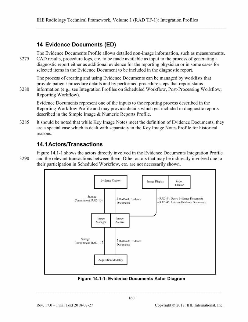
IHE Radiology Technical Framework, Volume 1 (RAD TF-1): Integration Profiles ______________________________________________________________________________
____________________________________________________________________________ 160
Rev. 17.0 – Final Text 2018-07-27 Copyright © 2018: IHE International, Inc.
14 Evidence Documents (ED) The Evidence Documents Profile allows detailed non-image information, such as measurements, CAD results, procedure logs, etc. to be made available as input to the process of generating a 3275 diagnostic report either as additional evidence for the reporting physician or in some cases for selected items in the Evidence Document to be included in the diagnostic report. The process of creating and using Evidence Documents can be managed by worklists that provide patient/ procedure details and by performed procedure steps that report status information (e.g., see Integration Profiles on Scheduled Workflow, Post-Processing Workflow, 3280 Reporting Workflow). Evidence Documents represent one of the inputs to the reporting process described in the Reporting Workflow Profile and may provide details which get included in diagnostic reports described in the Simple Image & Numeric Reports Profile. It should be noted that while Key Image Notes meet the definition of Evidence Documents, they 3285 are a special case which is dealt with separately in the Key Image Notes Profile for historical reasons.
14.1 Actors/Transactions Figure 14.1-1 shows the actors directly involved in the Evidence Documents Integration Profile and the relevant transactions between them. Other actors that may be indirectly involved due to 3290 their participation in Scheduled Workflow, etc. are not necessarily shown.
↓ RAD-44: Query Evidence Documents ↓ RAD-45: Retrieve Evidence Documents
Report Creator
Storage Commitment: RAD-10↓
↑ RAD-43: Evidence Documents S d
Storage Commitment: RAD-10 ↑
↓ RAD-43: Evidence Documents S d
Evidence Creator
Acquisition Modality
Image Manager
Image Archive
Image Display
Figure 14.1-1: Evidence Documents Actor Diagram

IHE Radiology Technical Framework, Volume 1 (RAD TF-1): Integration Profiles ______________________________________________________________________________
____________________________________________________________________________ 161
Rev. 17.0 – Final Text 2018-07-27 Copyright © 2018: IHE International, Inc.
Table 14.1-1 lists the transactions for each actor directly involved in the Evidence Documents Profile. In order to claim support of this integration profile, an implementation must perform the 3295 required transactions (labeled “R”). Transactions labeled “O” are optional. A complete list of options defined by this integration profile and that implementations may choose to support is listed in Section 14.2.
Table 14.1-1: Evidence Document Integration Profile - Actors and Transactions Actors Transactions Optionality TF Reference
Evidence Creator Storage Commitment [RAD-10] R RAD TF-2: 4.10 Evidence Documents Stored [RAD-43] R RAD TF-3: 4.43
Acquisition Modality Storage Commitment [RAD-10] R RAD TF-2: 4.10 Evidence Documents Stored [RAD-43] R RAD TF-3: 4.43
Image Manager/ Image Archive
Storage Commitment [RAD-10] R RAD TF-2: 4.10 Evidence Documents Stored [RAD-43] R RAD TF-3: 4.43 Query Evidence Documents [RAD-44] R RAD TF-3: 4.44 Retrieve Evidence Documents [RAD-45] R RAD TF-3: 4.45
Image Display (Report Creator)
Query Evidence Documents [RAD-44] R RAD TF-3: 4.44 Retrieve Evidence Documents [RAD-45] R RAD TF-3: 4.45
Note: Refer to Table 2-1 for other profiles that may be pre-requisites for this profile. 3300 If a Report Creator wishes to participate in this profile, it does not have to support any transactions directly, however it is required to be grouped with an Image Display in order to be able to Query/Retrieve the Evidence documents, and the Report Creator is expected to be able to transfer some contents of the retrieved document into the report it creates.
14.2 Evidence Documents Integration Profile Options 3305
Options that may be selected for this integration profile are listed in the Table 14.2-1 along with the Actors to which they apply. Dependencies between options when applicable are specified in notes.
Table 14.2-1: Evidence Documents - Actors and Options Actor Options TF Reference
Evidence Creator No options defined - -
Acquisition Modality No options defined - - Image Manager/ Image Archive
No options defined - -
No options defined - - Image Display (Report Creator)
No options defined - -
No options defined - -
IHE Radiology Technical Framework, Volume 1 (RAD TF-1): Integration Profiles ______________________________________________________________________________
____________________________________________________________________________ 162
Rev. 17.0 – Final Text 2018-07-27 Copyright © 2018: IHE International, Inc.
The Evidence Creator, Acquisition Modality and Image Manager/ Image Archive will likely 3310 support a variety of DICOM SOP Classes. Each DICOM SOP Class that is supported by the actor shall be listed in the product’s DICOM Conformance Statement. The IHE Integration Statement (see Appendix D) shall reference the DICOM Conformance Statement but does not repeat the list of DICOM SOP Classes that are considered to contain Evidence Documents. Examples of DICOM SOP Classes that may contain evidence are listed in RAD TF-3: 4.43, 3315 Table 4.43-1 and Table 4.43-2.
14.3 Evidence Document Process Flow Evidence Documents belong to the family of Evidence Objects that also includes Images, Presentation States, and Key Image Notes. These are objects generated as a result of performing procedure steps on systems in a clinical department. 3320 The start and completion of creating Evidence Documents is reported in the Scheduled Workflow Profile by the Evidence Creator using Creator Procedure Step In-Progress/Completed transactions, or by the Acquisition Modality using the Modality Procedure Step In-Progress/Completed; and in the Post-Processing Workflow by the Evidence Creator using the Workitem Procedure Step In-Progress/Completed transactions. 3325 As with other Evidence Objects, Evidence Documents are usually created by the system operator, and used by the reading physician in the process of creating a Diagnostic Report, either by reviewing or interpreting the Evidence Document contents, or by copying selected parts into the Report. Evidence Documents represent the uninterpreted information that is primarily managed and used inside an imaging department, although distribution outside the imaging 3330 department is not precluded. In contrast, the diagnostic reports described in the Simple Image and Numeric Reports Profile represent the interpreted information which is the primary output of the imaging department and are available for wide distribution. Due to the difference between the way the Evidence Creator reports status in the Scheduled Workflow Profile (using a Creator Procedure Step transaction to the Performed Procedure Step 3335 Manager) and the way the Evidence Creator reports status in the Post-Processing Workflow Profile (using a Workitem PPS transaction to the Post-Processing Workflow Manager), two examples of the process flow will be shown below. The scheduling part of the workflow that would typically precede the part of the workflow in the following diagram can be seen in Figure 3.2-1 (Administrative Process Flow) in the Scheduled 3340 Workflow Profile.
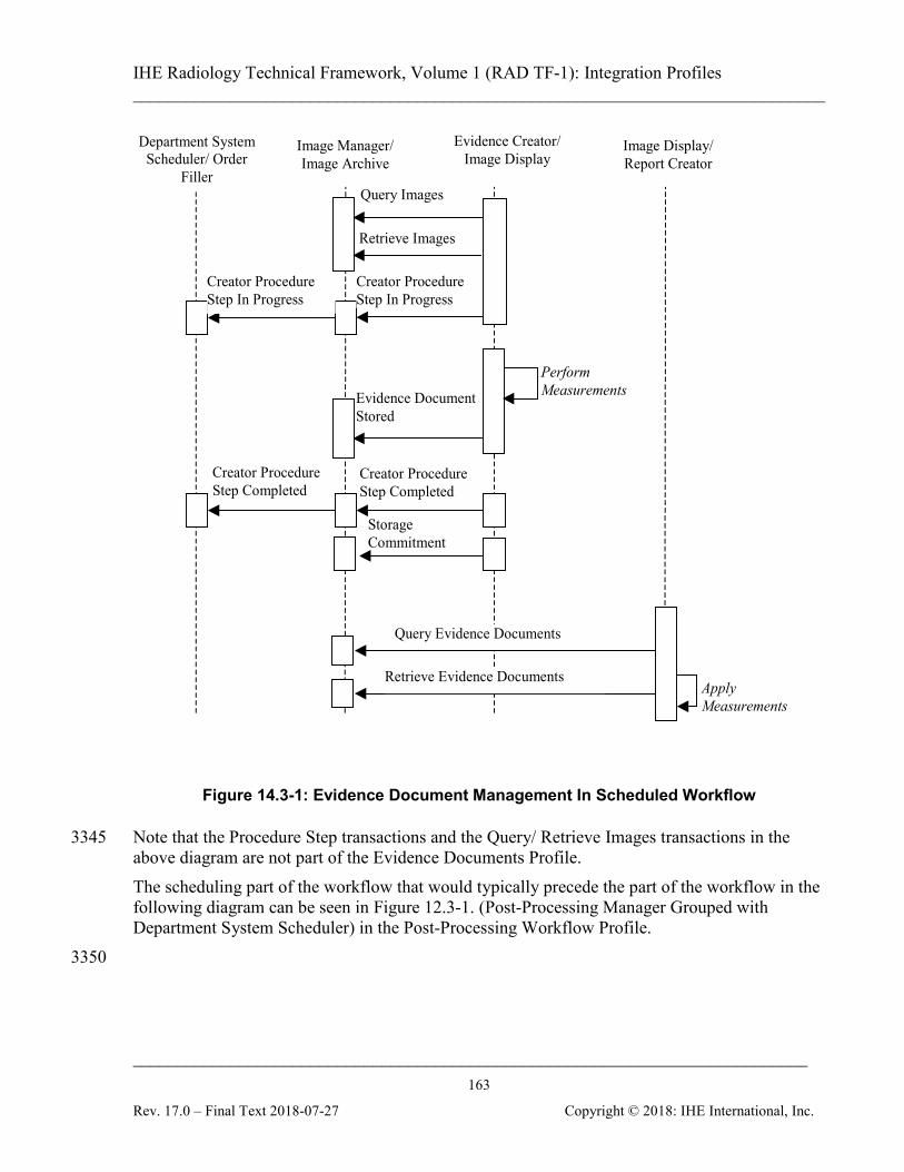
IHE Radiology Technical Framework, Volume 1 (RAD TF-1): Integration Profiles ______________________________________________________________________________
____________________________________________________________________________ 163
Rev. 17.0 – Final Text 2018-07-27 Copyright © 2018: IHE International, Inc.
Evidence Document Stored
Image Manager/ Image Archive
Evidence Creator/ Image Display
Department System Scheduler/ Order
Filler
Creator Procedure Step Completed
Perform Measurements
Storage Commitment
Creator Procedure Step In Progress
Creator Procedure Step Completed
Creator Procedure Step In Progress
Image Display/ Report Creator
Query Evidence Documents
Retrieve Evidence Documents Apply Measurements
Query Images
Retrieve Images
Figure 14.3-1: Evidence Document Management In Scheduled Workflow
Note that the Procedure Step transactions and the Query/ Retrieve Images transactions in the 3345 above diagram are not part of the Evidence Documents Profile. The scheduling part of the workflow that would typically precede the part of the workflow in the following diagram can be seen in Figure 12.3-1. (Post-Processing Manager Grouped with Department System Scheduler) in the Post-Processing Workflow Profile. 3350
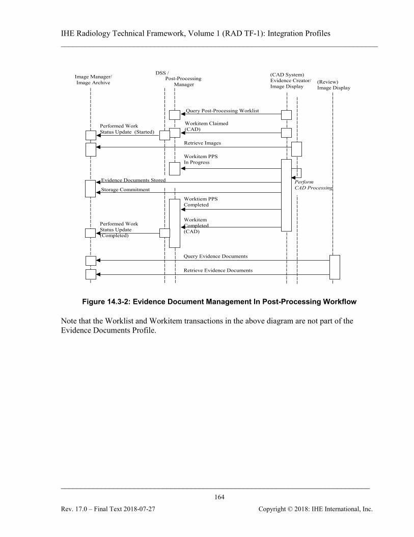
IHE Radiology Technical Framework, Volume 1 (RAD TF-1): Integration Profiles ______________________________________________________________________________
____________________________________________________________________________ 164
Rev. 17.0 – Final Text 2018-07-27 Copyright © 2018: IHE International, Inc.
Query Evidence Documents
Image Manager/ Image Archive
DSS / (CAD System) Evidence Creator/ Image Display
(Review) Image Display
Query Post-Processing Worklist
Post-Processing Manager
Workitem Claimed (CAD)
Retrieve Images
Evidence Documents Stored
Workitem PPS In Progress
Worktiem PPS Completed
Workitem Completed (CAD)
Perform CAD Processing
Performed Work Status Update (Completed)
Performed Work Status Update (Started)
Storage Commitment
Retrieve Evidence Documents
Figure 14.3-2: Evidence Document Management In Post-Processing Workflow
Note that the Worklist and Workitem transactions in the above diagram are not part of the Evidence Documents Profile.
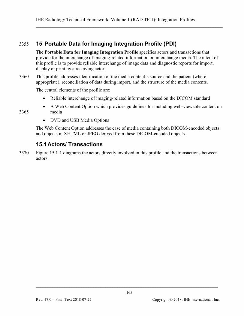
IHE Radiology Technical Framework, Volume 1 (RAD TF-1): Integration Profiles ______________________________________________________________________________
____________________________________________________________________________ 165
Rev. 17.0 – Final Text 2018-07-27 Copyright © 2018: IHE International, Inc.
15 Portable Data for Imaging Integration Profile (PDI) 3355
The Portable Data for Imaging Integration Profile specifies actors and transactions that provide for the interchange of imaging-related information on interchange media. The intent of this profile is to provide reliable interchange of image data and diagnostic reports for import, display or print by a receiving actor. This profile addresses identification of the media content’s source and the patient (where 3360 appropriate), reconciliation of data during import, and the structure of the media contents. The central elements of the profile are:
• Reliable interchange of imaging-related information based on the DICOM standard
• A Web Content Option which provides guidelines for including web-viewable content on media 3365
• DVD and USB Media Options
The Web Content Option addresses the case of media containing both DICOM-encoded objects and objects in XHTML or JPEG derived from these DICOM-encoded objects.
15.1 Actors/ Transactions Figure 15.1-1 diagrams the actors directly involved in this profile and the transactions between 3370 actors.
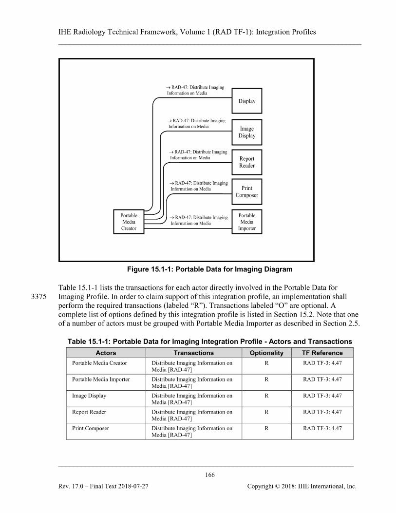
IHE Radiology Technical Framework, Volume 1 (RAD TF-1): Integration Profiles ______________________________________________________________________________
____________________________________________________________________________ 166
Rev. 17.0 – Final Text 2018-07-27 Copyright © 2018: IHE International, Inc.
Print Composer
Portable Media
Importer
Report Reader
Portable Media Creator
Image Display
Display
→ RAD-47: Distribute Imaging Information on Media
→ RAD-47: Distribute Imaging Information on Media
→ RAD-47: Distribute Imaging Information on Media
→ RAD-47: Distribute Imaging Information on Media
→ RAD-47: Distribute Imaging Information on Media
Figure 15.1-1: Portable Data for Imaging Diagram
Table 15.1-1 lists the transactions for each actor directly involved in the Portable Data for Imaging Profile. In order to claim support of this integration profile, an implementation shall 3375 perform the required transactions (labeled “R”). Transactions labeled “O” are optional. A complete list of options defined by this integration profile is listed in Section 15.2. Note that one of a number of actors must be grouped with Portable Media Importer as described in Section 2.5.
Table 15.1-1: Portable Data for Imaging Integration Profile - Actors and Transactions Actors Transactions Optionality TF Reference
Portable Media Creator Distribute Imaging Information on Media [RAD-47]
R RAD TF-3: 4.47
Portable Media Importer Distribute Imaging Information on Media [RAD-47]
R RAD TF-3: 4.47
Image Display Distribute Imaging Information on Media [RAD-47]
R RAD TF-3: 4.47
Report Reader Distribute Imaging Information on Media [RAD-47]
R RAD TF-3: 4.47
Print Composer Distribute Imaging Information on Media [RAD-47]
R RAD TF-3: 4.47

IHE Radiology Technical Framework, Volume 1 (RAD TF-1): Integration Profiles ______________________________________________________________________________
____________________________________________________________________________ 167
Rev. 17.0 – Final Text 2018-07-27 Copyright © 2018: IHE International, Inc.
Actors Transactions Optionality TF Reference Display (ITI TF) Distribute Imaging Information on
Media [RAD-47] R RAD TF-3: 4.47
3380
15.2 Portable Data for Imaging Integration Profile Options Options that may be selected for this integration profile are listed in Table 15.2-1 along with the actors to which they apply. Dependencies between options when applicable are specified in notes.
Table 15.2-1: Portable Data for Imaging - Actors and Options 3385 Actor Options TF Reference
Portable Media Creator Web Content RAD TF-1: 15.4.2 RAD TF-3: 4.47.4.1.2
DVD Media
RAD TF-1: 15.4.4 RAD TF-3: 4.47.4.1.4.1
USB Media RAD TF-1: 15.4.4 RAD TF-3: 4.47.4.1.4.2
Portable Media Importer DVD Media
RAD TF-1: 15.4.4 RAD TF-3: 4.47.4.1.4.1
USB Media RAD TF-1: 15.4.4 RAD TF-3: 4.47.4.1.4.2
Image Display DVD Media
RAD TF-1: 15.4.4 RAD TF-3: 4.47.4.1.4.1
USB Media RAD TF-1: 15.4.4 RAD TF-3: 4.47.4.1.4.2
Report Reader DVD Media
RAD TF-1: 15.4.4 RAD TF-3: 4.47.4.1.4.1
USB Media RAD TF-1: 15.4.4 RAD TF-3: 4.47.4.1.4.2
Print Composer DVD Media
RAD TF-1: 15.4.4 RAD TF-3: 4.47.4.1.4.1
USB Media RAD TF-1: 15.4.4 RAD TF-3: 4.47.4.1.4.2
Display No options defined -
15.3 Portable Data for Imaging Process Flow This section describes the typical process flow related to the use of Interchange Media. The transaction covered is Distribute Imaging Information on Media [RAD-47]. The following steps can be identified in this process flow: 3390
IHE Radiology Technical Framework, Volume 1 (RAD TF-1): Integration Profiles ______________________________________________________________________________
____________________________________________________________________________ 168
Rev. 17.0 – Final Text 2018-07-27 Copyright © 2018: IHE International, Inc.
• The source actor (Portable Media Creator) writes a group of image dataset(s) and/or the associated diagnostic report(s) onto a piece of interchange media. It is presumed that the Portable Media Creator has access to the data from a grouped actor, or another source outside the scope of IHE.
• The media is physically transported to a destination where the imaging-related 3395 information contained on the media will be used.
• The Portable Media Importer reads DICOM objects (images, presentation states, key image notes, evidence documents and reports) on the media and imports them into the local information space. The Portable Media Importer reconciles the data as needed (e.g., to change the recorded Patient ID to the local Patient ID). If some classes of DICOM 3400 objects are present on the media and cannot be imported, the Portable Media Importer notifies the operator of the studies and series affected and makes clear that they are not supported by the importing application.
• The Image Display, Report Reader, Display or Print Composer reads the objects it supports and renders them depending on the receiver’s needs. If some objects are not 3405 supported by the reading application it notifies the operator that those objects are not supported.
The potential usage scenarios of the data are described in the use cases below.
15.3.1 Use Cases This profile is not intended to provide an archival solution. The matter of whether or not CD, 3410 DVD or USB media are suitably robust for long-term archive is not addressed by IHE. Use Case 1 - Patient/Referring Physician Viewing: Diagnostic and therapeutic imaging data, such as images and reports, is received on media potentially serving multiple use cases. The patient or the referring physician can view the data, either with a viewer application residing on the same media or using a web browser. For security and privacy reasons, media given to a 3415 patient would not contain data of other patients. Refer to Section 15.5 for additional security considerations. Use Case 2 - Healthcare Enterprise Interchange: One or more patients’ data, such as images, reports or complete studies, is received on media to enable a diagnostic or therapeutic care process. Media data are imported at a different site, generally for the purpose of a “second read 3420 import” or “reference import”.
• Second Read Import: Media data is imported to the Image Manager/Archive to be read/over read. In order to avoid data conflicts, key patient/study attributes may need to be reconciled with existing local data. Images and related presentation states can be sent to a Print Composer to be printed. 3425
• Reference Import: Media data is imported to the Image Manager/Archive and/or Report Repository to become part of the patient history. It may be used as “relevant prior” data for future reads. In order to avoid data conflicts, key patient/study attributes may need to be reconciled with existing local data.
IHE Radiology Technical Framework, Volume 1 (RAD TF-1): Integration Profiles ______________________________________________________________________________
____________________________________________________________________________ 169
Rev. 17.0 – Final Text 2018-07-27 Copyright © 2018: IHE International, Inc.
Use Case 3 - Operating Room Viewing: Media data is used to enable diagnostic or therapeutic 3430 processes in environments without a reliable network connection. The volume of data can be very large and may contain image data, post-processing results and reports. In the operating room, the surgical staff receives the media and reads its contents using advanced viewing capabilities, which may include manipulating or processing images.
15.3.2 Process Flow Description 3435 The use cases can be specified in terms of three media-related activities:
• Media Export
• Media Viewing
• Media Import
Media Export (All Use Cases): 3440 The Portable Media Creator assembles the media content (DICOM and web-viewable content) and writes it to the physical medium. The following sequence of activities will be performed during media creation:
• Export of DICOM data (FSC activity).
• Optionally, export of web-viewable data, which involves deriving easily accessible 3445 informative data from the DICOM data (Web Content Option).
• Optionally, inclusion of additional content (e.g., a DICOM Viewer or viewing software components on the media to access DICOM data).
B) Media Viewing: B1) Web (Use Case 1) (care providers, other users and patients without DICOM viewing 3450 equipment or software): Any web-viewable media content is received and displayed by a Display Actor, which exists as a generally available resource (i.e., web browser). Note that the Portable Media Creator cannot rely on the presence of web-viewable content on all media since it will be included only on media created using the Web Content Option). 3455 B2) DICOM (Use Case 1 and 3) (users with DICOM viewing equipment or software): The DICOM portion of the media content is displayed using specialized applications pre-existing in the reading environment or included on the media itself. The variety of DICOM objects that an Image Display and/or Report Reader Actor can process is indicated by its support of the corresponding content profiles. The Print Composer Actor 3460 sends images from the media to a Print Server for printing.
C) Media Import (Use Case 2): The “Media Import” activity is accomplished by a Portable Media Importer and deals exclusively with the DICOM portion of the media content. The Portable Media Importer Actor is

IHE Radiology Technical Framework, Volume 1 (RAD TF-1): Integration Profiles ______________________________________________________________________________
____________________________________________________________________________ 170
Rev. 17.0 – Final Text 2018-07-27 Copyright © 2018: IHE International, Inc.
grouped with one or more content actors (Evidence Creator, Report Creator, etc.), depending on 3465 the type of media content to be imported. The grouped actor provides storage capability for the media data accessed by the Portable Media Importer. The Portable Media Importer Actor accesses all DICOM instances referenced by the DICOMDIR file and enables the user to select a media patient dataset to be imported.
• The Portable Media Importer obtains local data that is known to be accurate within the 3470 importing institution/enterprise and reconciles “key attributes” of patient and study information (when required). A method for performing these steps is documented in the Import Reconciliation Workflow Profile (see Section 3.21). Refer to RAD TF-3: 4.47.4.1.3 for the list of “key attributes” and the related reconciliation actions to be performed. Note: The Portable Media Importer may for example be grouped with an Evidence Creator to allow the storage of its 3475
diagnostic and therapeutic imaging content to an Image Manager/Image Archive, or grouped with a Report Creator to store reports on a Report Repository. This enables use of the content for subsequent “relevant prior” data for future reads. A grouping with an Acquisition Modality Actor could also be used to allow subsequent “reads/over reads”. In the case of a Portable Media Importer grouped with the Print Composer Actor, the imported content (images and presentation states) can be sent to the Print Server to be printed. 3480
Figure 15.3.2-1 shows an example flow of events covering the use cases described in the previous sections.

IHE Radiology Technical Framework, Volume 1 (RAD TF-1): Integration Profiles ______________________________________________________________________________
____________________________________________________________________________ 171
Rev. 17.0 – Final Text 2018-07-27 Copyright © 2018: IHE International, Inc.
Portable Media Creator
Assemble Media Content
Evidence Creator
Distribute Imaging
Information on Media
Evidence Object Display
Image Display
Image Manager/ Archive
Access DICOM Directory Info
Portable Media
Importer
Report Submission
Reconcile patient/study data on media using data locally obtained
Display
Web Viewing
Export
Web Viewing
DICOM Viewing
Import
Report Manager
Creator Images Stored
Access DICOM Directory Info
Report Creator
Store Diagnostic Reports
Store Evidence Images
Distribute Imaging
Information on Media
Distribute Imaging
Information on Media
Figure 15.3.2-1: Portable Data for Imaging Process Flow
3485
IHE Radiology Technical Framework, Volume 1 (RAD TF-1): Integration Profiles ______________________________________________________________________________
____________________________________________________________________________ 172
Rev. 17.0 – Final Text 2018-07-27 Copyright © 2018: IHE International, Inc.
15.4 Media Content The requirements on media content are intended to promote the reliable transfer of imaging data, including diagnostic reports, and to allow for the viewing of images and reports on general purpose computers. The intent is that the media content be a “complete set of images of diagnostic quality” (a quote 3490 from a statement on the matter by the American Medical Association Expert Panel on Medical Imaging). The media content can be accessed via two "entry points" on the media: the DICOMDIR file for DICOM imaging information and optionally the INDEX.HTM file for web-viewable content. Created media are required to contain DICOM data and may optionally include web-viewable 3495 data derived from it. This web-viewable data, if present, shall faithfully preserve the clinical intent of the original DICOM information.
15.4.1 DICOM Content The DICOM data shall be created by using the DICOM Media Storage Application Profile appropriate for the content as defined in the Distribute Imaging Information on Media 3500 transaction and depending on the Options supported by the Portable Media Creator. The DICOMDIR file shall reference all DICOM files stored on the media. DICOM files shall not be placed in the root directory, but no constraints are placed on the name of directory that contains them.
15.4.2 Web Content Option 3505 Portable Media Creators implementing the Web Content Option may also include web-viewable data on the media. The web-viewable data shall be derived from the DICOM information as XHTML files and referenced JPEG images. The XHTML entry page (INDEX.HTM) shall allow access to all of this data. This enables end-users to access relevant media content using a generally available 3510 web browser. The INDEX.HTM file shall be placed in the root directory. Note that the web-viewable data specified in this integration profile reflects the full set of the exported DICOM data or a subset considered at the time of creation to faithfully represent the patient's clinical condition. For example, if a DICOM Structured Report references only Key Images and a larger DICOM dataset, the web-viewable data derived from it may selectively 3515 include the report in XHTML format and only JPEG images derived from the DICOM Key Images.
15.4.3 Other Content Viewing applications (for example a DICOM Media Viewer) may optionally be included on the media. Such viewers may have launch links included in the HTML. Including such viewers on 3520 the media is discouraged due to security issues discussed in the next section, as well as potential interoperability problems.
IHE Radiology Technical Framework, Volume 1 (RAD TF-1): Integration Profiles ______________________________________________________________________________
____________________________________________________________________________ 173
Rev. 17.0 – Final Text 2018-07-27 Copyright © 2018: IHE International, Inc.
Additional data (e.g., a diagnostic report in non-DICOM format) may be also included on the media. Since the format of any such data is not specified by this profile, such data shall be placed in a separate directory on the media. If such data is referenced in the INDEX.HTM file, it shall 3525 be clearly indicated that this content was not generated in conformance with the IHE Radiology Technical Framework, and its reliable import has not been addressed.
15.4.4 Media Type (CD, DVD and USB) The baseline media type is CD with uncompressed images. Named options for support of compressed images (using JPEG lossy and lossless and JPEG 2000 3530 reversible and irreversible) on DVD and USB media are defined. Compressed images on CD, such as are commonly used for cardiac angiography and for cine ultrasound, are supported through the use of the DVD Media Option, which allows for CD as a media type that can be read by DVD drives.
15.5 Security and Privacy Aspects 3535
Portable Media Creator Actors shall make a reasonable effort to ensure that no malicious software (viruses, etc.) is present on created media. The automatic launch of applications from media poses a risk that malicious software could be started and it is recommended that media reading actors not allow automatic launching. Portable Media Creators should therefore also avoid using automatic launching. This includes not 3540 automatically launching a DICOM media viewer that may be present on the media. Furthermore, if a DICOM media viewer is present, security issues at the receiving actor are minimized by:
• working under normal (restricted) user privileges and not requiring the user to work with administrator or root privileges and 3545
• not needing software installed on the computer where the media is used. Audit trails to track export/import/viewing activities are addressed in ITI TF-2: 3.20 and RAD TF-3: 5.1. Portable Media Creator and media reading actors that claim support of the Audit Trail and Node Authentication Integration Profile shall generate such audit trail entries. Encryption of data and other access controls to media content are not addressed in this profile. 3550 Media created using this profile should be considered to be unlocked information (e.g., like paper records). Such media should be handled according to appropriate site policies (e.g., do not give a patient a disk containing data from other patients, do not leave disks where they can be taken by unauthorized persons, etc.). For many Use Cases it is not appropriate to place data from multiple patients on a single volume 3555 of media for security and privacy reasons. It is not good practice to include on media, either in the physical label, in the DICOMDIR or DICOM instances, the Web Content or any other content, such sensitive information as the patient’s address, telephone number or national identifier (such as a US Social Security

IHE Radiology Technical Framework, Volume 1 (RAD TF-1): Integration Profiles ______________________________________________________________________________
____________________________________________________________________________ 174
Rev. 17.0 – Final Text 2018-07-27 Copyright © 2018: IHE International, Inc.
Number), which might be used for unauthorized purposes such as identity theft or fraud. Though 3560 it is not a requirement of this profile to require the Portable Media Creator to remove any such information from any DICOM instances received prior to encoding on media, it is strongly recommended.
IHE Radiology Technical Framework, Volume 1 (RAD TF-1): Integration Profiles ______________________________________________________________________________
____________________________________________________________________________ 175
Rev. 17.0 – Final Text 2018-07-27 Copyright © 2018: IHE International, Inc.
16 NM Image Integration Profile The NM Image Profile specifies how NM Images are to be stored by Acquisition Modalities and 3565 Evidence Creator workstations and how Image Displays should retrieve and make use of them. It defines the basic display capabilities Image Displays are expected to provide, (such as might be sufficient for a referring physician) but does not address advanced review features. It also defines how result screens, both static and dynamic, such as those created by NM Cardiac Processing Packages, should be stored using DICOM objects that can be displayed on general 3570 purpose Image Display systems. Note that the NM Image Profile is undergoing revision, and vendors considering implementation are advised to include the modifications contained in the trial implementation version “NM Image Profile with Cardiac Option”. For additional information please contact the IHE Radiology Technical Committee at [email protected]. 3575 The NM Image Profile can be enhanced by combining it with workflow profiles such as Scheduled Workflow, Post-Processing Workflow and Reporting Workflow which address how to schedule, manage and report the status of the steps in which NM Image objects are created.
16.1 Actors/ Transactions Figure 16.1-1 shows the actors directly involved in the NM Image Integration Profile and the 3580 relevant transactions between them. Other actors that may be indirectly involved due to their participation in the Scheduled Workflow Profile, the Post-Processing Workflow Profile, etc. are not necessarily shown.
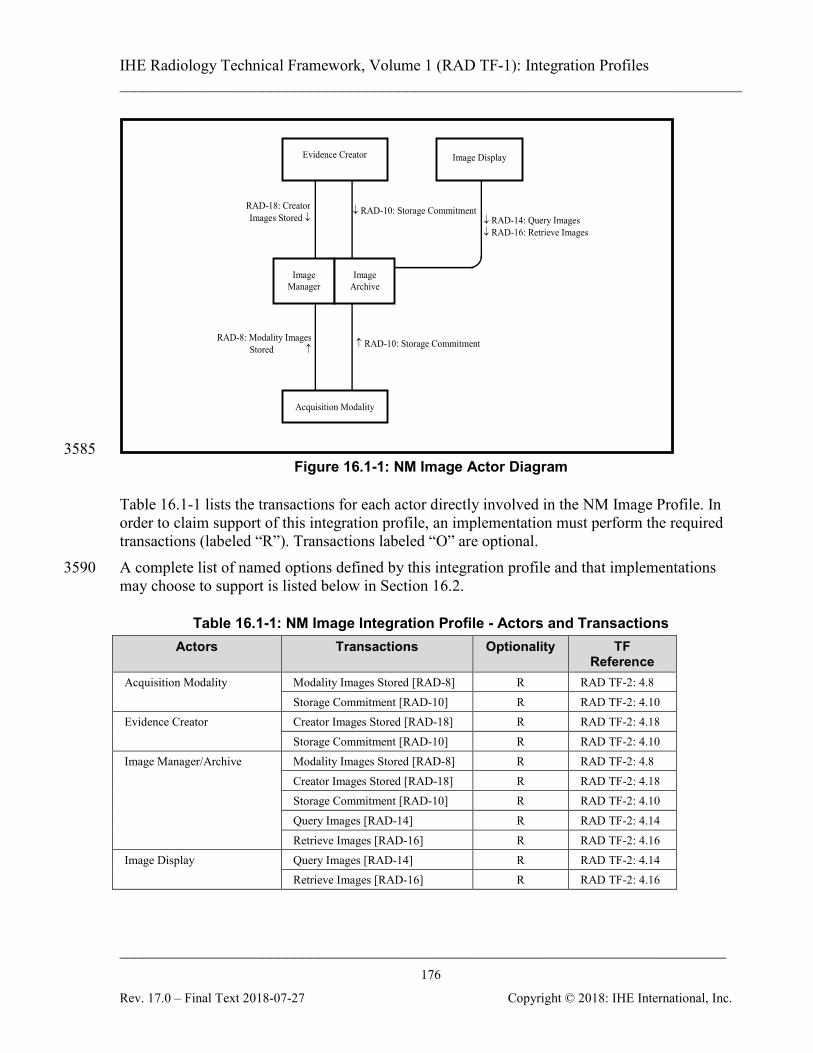
IHE Radiology Technical Framework, Volume 1 (RAD TF-1): Integration Profiles ______________________________________________________________________________
____________________________________________________________________________ 176
Rev. 17.0 – Final Text 2018-07-27 Copyright © 2018: IHE International, Inc.
↓ RAD-14: Query Images ↓ RAD-16: Retrieve Images
RAD-18: Creator Images Stored ↓
↓ RAD-10: Storage Commitment
Evidence Creator
Acquisition Modality
Image Manager
Image Archive
Image Display
RAD-8: Modality Images Stored ↑ ↑ RAD-10: Storage Commitment
3585 Figure 16.1-1: NM Image Actor Diagram
Table 16.1-1 lists the transactions for each actor directly involved in the NM Image Profile. In order to claim support of this integration profile, an implementation must perform the required transactions (labeled “R”). Transactions labeled “O” are optional. A complete list of named options defined by this integration profile and that implementations 3590 may choose to support is listed below in Section 16.2.
Table 16.1-1: NM Image Integration Profile - Actors and Transactions Actors Transactions Optionality TF
Reference Acquisition Modality Modality Images Stored [RAD-8] R RAD TF-2: 4.8
Storage Commitment [RAD-10] R RAD TF-2: 4.10 Evidence Creator Creator Images Stored [RAD-18] R RAD TF-2: 4.18
Storage Commitment [RAD-10] R RAD TF-2: 4.10 Image Manager/Archive Modality Images Stored [RAD-8] R RAD TF-2: 4.8
Creator Images Stored [RAD-18] R RAD TF-2: 4.18 Storage Commitment [RAD-10] R RAD TF-2: 4.10 Query Images [RAD-14] R RAD TF-2: 4.14 Retrieve Images [RAD-16] R RAD TF-2: 4.16
Image Display Query Images [RAD-14] R RAD TF-2: 4.14 Retrieve Images [RAD-16] R RAD TF-2: 4.16

IHE Radiology Technical Framework, Volume 1 (RAD TF-1): Integration Profiles ______________________________________________________________________________
____________________________________________________________________________ 177
Rev. 17.0 – Final Text 2018-07-27 Copyright © 2018: IHE International, Inc.
To participate as an evidence creator in Nuclear Medicine, the system must create derivative data from original NM modality image data. Examples of such derivative data include:
a) Reconstruction, reorientation, filtering, or other processing of NM data, with output of 3595 NM modality image objects. b) Quantization of NM data, with the display and storage of result screens as SC or MFSC image objects. c) Registration between an NM data set and another data set.
For all NM modality objects created, the evidence creator must meet the requirements of an 3600 acquisition modality with respect to encoding, storage, and inclusion of required DICOM tags, as noted in RAD TF-2: 4.8.4.1.2.2. If the system creates SC or MFSC objects, the evidence creator is encouraged to support the Result Screen Export Option, and conform to the requirements of this option for any stored result screens. 3605
16.2 NM Image Integration Profile Options Options that may be selected for this integration profile are listed in the Table 16.2-1 along with the Actors to which they apply. Dependencies between options when applicable are specified in notes.
Table 16.2-1: Evidence Documents - Actors and Options 3610 Actor Options TF Reference
Acquisition Modality No options defined --
Evidence Creator Result Screen Export Option RAD TF-2: 4.18.4.1.2.4 RAD TF-2: 4.16.4.2.2.4
Image Archive/Manager No options defined --
Image Display Review Option RAD TF-2: 4.16.4.2.2.2.5
The NM Image Profile is designed to provide faithful and complete storage and retrieval of NM data and sufficient display functionality to allow adequate review of nuclear medicine images by referring physicians. It should also be sufficient for secondary review (without reprocessing capability) of cardiac nuclear medicine studies by cardiologists and for correlation of nuclear 3615 medicine images with other imaging modalities during review by general radiologists. The Review Option is intended to add functionality for primary (non-cardiac) NM interpretation. The Result Screen Export Option adds functionality for storing Result Screens (which may be static or may contain moving components) in commonly displayable DICOM formats. Acquisition Modality Actors which support Result Screen Export should claim the appropriate 3620 options as an Evidence Creator.
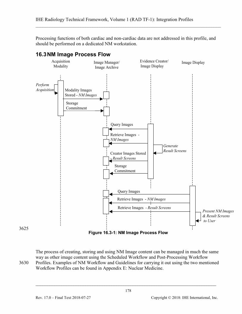
IHE Radiology Technical Framework, Volume 1 (RAD TF-1): Integration Profiles ______________________________________________________________________________
____________________________________________________________________________ 178
Rev. 17.0 – Final Text 2018-07-27 Copyright © 2018: IHE International, Inc.
Processing functions of both cardiac and non-cardiac data are not addressed in this profile, and should be performed on a dedicated NM workstation.
16.3 NM Image Process Flow
Perform Acquisition
Creator Images Stored - Result Screens
Image Manager/ Image Archive
Evidence Creator/ Image Display
Acquisition Modality
Generate Result Screens
Storage Commitment
Modality Images Stored - NM Images
Image Display
Query Images
Retrieve Images - NM Images
Present NM Images & Result Screens to User
Query Images
Retrieve Images - NM Images
Retrieve Images - Result Screens
Storage Commitment
3625 Figure 16.3-1: NM Image Process Flow
The process of creating, storing and using NM Image content can be managed in much the same way as other image content using the Scheduled Workflow and Post-Processing Workflow Profiles. Examples of NM Workflow and Guidelines for carrying it out using the two mentioned 3630 Workflow Profiles can be found in Appendix E: Nuclear Medicine.

IHE Radiology Technical Framework, Volume 1 (RAD TF-1): Integration Profiles ______________________________________________________________________________
____________________________________________________________________________ 179
Rev. 17.0 – Final Text 2018-07-27 Copyright © 2018: IHE International, Inc.
17 Teaching File and Clinical Trial Export (TCE) This profile defines a means of selecting the relevant images, key image notes, reports, evidence documents and presentation states on the Export Selector (which would typically be grouped with an Acquisition Modality, Image Display, Evidence Creator or Report Creator), a means to 3635 enter additional information at that time, a means of transfer to an Export Manager Actor whose behavior is defined, and a means of transfer to a Receiver Actor whose behavior is not defined (but which might be a teaching file authoring or distribution system, clinical trial image management system, or a publication authoring system or might be grouped with an Image Manager/Archive or Portable Media Creator). 3640
17.1 Actors/Transactions Figure 17.1-1 shows the actors directly involved in the Teaching File and Clinical Trial Export Integration Profile and the relevant transactions between them. Other actors that may be indirectly involved due to their participation in Key Image Note, Consistent Presentation of Images, Evidence Document, Simple Image and Numeric Report and Portable Data for Imaging 3645 Profiles, etc. are not shown.
Export Ins tances [RAD-53] ↓
Export Manager
Store Instances [RAD-50] ↓
↓ Store Export Selection [RAD-51]
↓ Store Additional Teaching File Inform ation [RAD-52]
Export Selector
Receiver
Figure 17.1-1: Teaching File and Clinical Trial Export Actor Diagram
Table 17.1-1 lists the transactions for each actor directly involved in the Teaching File and 3650 Clinical Trial Export Profile. In order to claim support of this integration profile, an implementation must perform the required transactions (labeled “R”). Transactions labeled “O” are optional. A complete list of options defined by this integration profile and that implementations may choose to support is listed in Section 17.2.
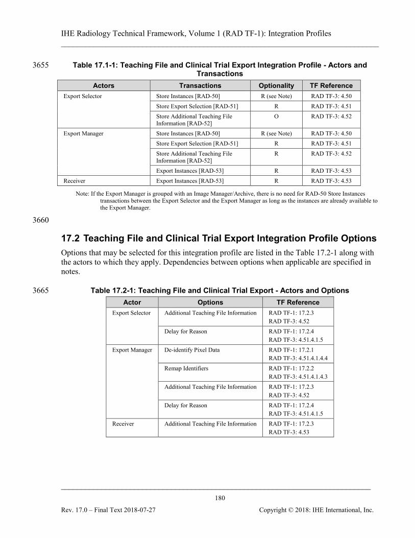
IHE Radiology Technical Framework, Volume 1 (RAD TF-1): Integration Profiles ______________________________________________________________________________
____________________________________________________________________________ 180
Rev. 17.0 – Final Text 2018-07-27 Copyright © 2018: IHE International, Inc.
Table 17.1-1: Teaching File and Clinical Trial Export Integration Profile - Actors and 3655 Transactions
Actors Transactions Optionality TF Reference Export Selector Store Instances [RAD-50] R (see Note) RAD TF-3: 4.50
Store Export Selection [RAD-51] R RAD TF-3: 4.51 Store Additional Teaching File Information [RAD-52]
O RAD TF-3: 4.52
Export Manager Store Instances [RAD-50] R (see Note) RAD TF-3: 4.50 Store Export Selection [RAD-51] R RAD TF-3: 4.51 Store Additional Teaching File Information [RAD-52]
R RAD TF-3: 4.52
Export Instances [RAD-53] R RAD TF-3: 4.53 Receiver Export Instances [RAD-53] R RAD TF-3: 4.53
Note: If the Export Manager is grouped with an Image Manager/Archive, there is no need for RAD-50 Store Instances transactions between the Export Selector and the Export Manager as long as the instances are already available to the Export Manager.
3660
17.2 Teaching File and Clinical Trial Export Integration Profile Options Options that may be selected for this integration profile are listed in the Table 17.2-1 along with the actors to which they apply. Dependencies between options when applicable are specified in notes.
Table 17.2-1: Teaching File and Clinical Trial Export - Actors and Options 3665 Actor Options TF Reference
Export Selector Additional Teaching File Information RAD TF-1: 17.2.3 RAD TF-3: 4.52
Delay for Reason RAD TF-1: 17.2.4 RAD TF-3: 4.51.4.1.5
Export Manager De-identify Pixel Data RAD TF-1: 17.2.1 RAD TF-3: 4.51.4.1.4.4
Remap Identifiers RAD TF-1: 17.2.2 RAD TF-3: 4.51.4.1.4.3
Additional Teaching File Information RAD TF-1: 17.2.3 RAD TF-3: 4.52
Delay for Reason RAD TF-1: 17.2.4 RAD TF-3: 4.51.4.1.5
Receiver Additional Teaching File Information RAD TF-1: 17.2.3 RAD TF-3: 4.53
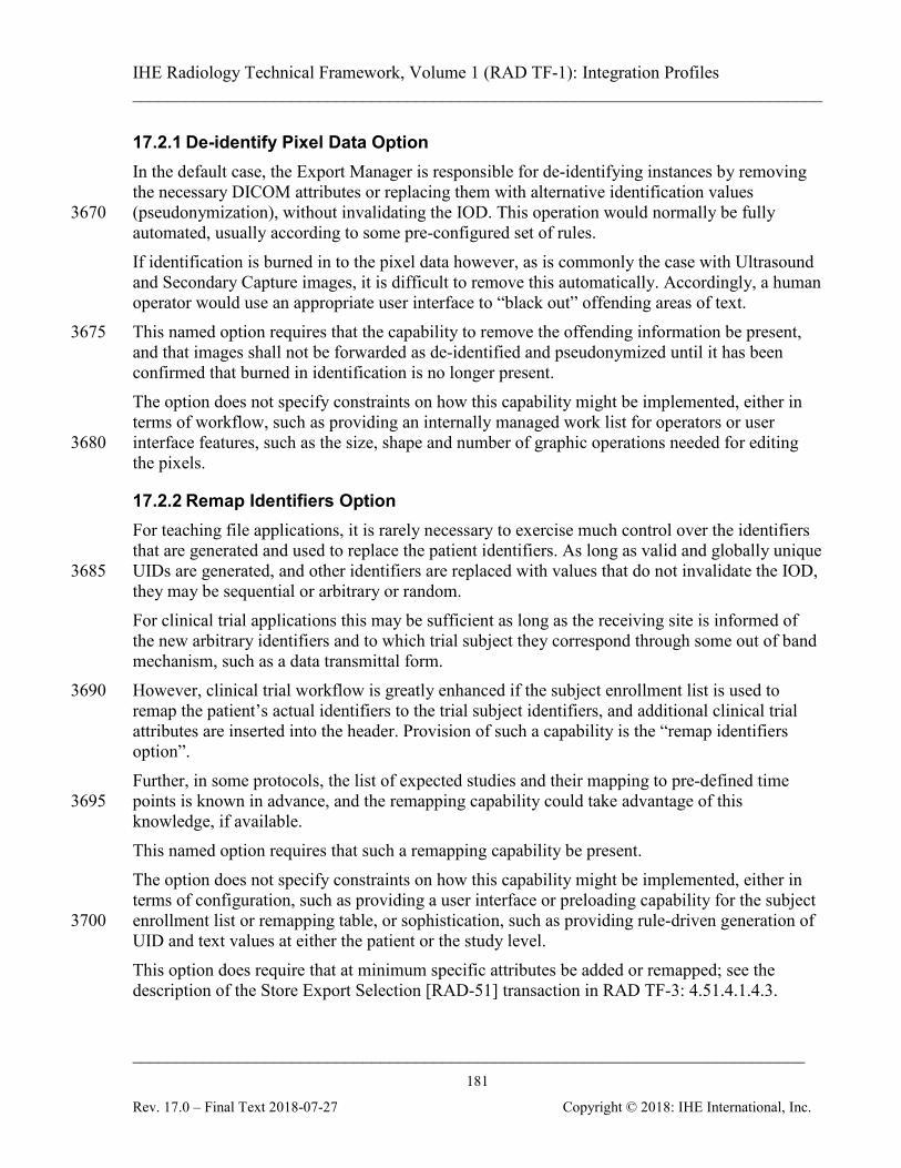
IHE Radiology Technical Framework, Volume 1 (RAD TF-1): Integration Profiles ______________________________________________________________________________
____________________________________________________________________________ 181
Rev. 17.0 – Final Text 2018-07-27 Copyright © 2018: IHE International, Inc.
17.2.1 De-identify Pixel Data Option In the default case, the Export Manager is responsible for de-identifying instances by removing the necessary DICOM attributes or replacing them with alternative identification values (pseudonymization), without invalidating the IOD. This operation would normally be fully 3670 automated, usually according to some pre-configured set of rules. If identification is burned in to the pixel data however, as is commonly the case with Ultrasound and Secondary Capture images, it is difficult to remove this automatically. Accordingly, a human operator would use an appropriate user interface to “black out” offending areas of text. This named option requires that the capability to remove the offending information be present, 3675 and that images shall not be forwarded as de-identified and pseudonymized until it has been confirmed that burned in identification is no longer present. The option does not specify constraints on how this capability might be implemented, either in terms of workflow, such as providing an internally managed work list for operators or user interface features, such as the size, shape and number of graphic operations needed for editing 3680 the pixels.
17.2.2 Remap Identifiers Option For teaching file applications, it is rarely necessary to exercise much control over the identifiers that are generated and used to replace the patient identifiers. As long as valid and globally unique UIDs are generated, and other identifiers are replaced with values that do not invalidate the IOD, 3685 they may be sequential or arbitrary or random. For clinical trial applications this may be sufficient as long as the receiving site is informed of the new arbitrary identifiers and to which trial subject they correspond through some out of band mechanism, such as a data transmittal form. However, clinical trial workflow is greatly enhanced if the subject enrollment list is used to 3690 remap the patient’s actual identifiers to the trial subject identifiers, and additional clinical trial attributes are inserted into the header. Provision of such a capability is the “remap identifiers option”. Further, in some protocols, the list of expected studies and their mapping to pre-defined time points is known in advance, and the remapping capability could take advantage of this 3695 knowledge, if available. This named option requires that such a remapping capability be present. The option does not specify constraints on how this capability might be implemented, either in terms of configuration, such as providing a user interface or preloading capability for the subject enrollment list or remapping table, or sophistication, such as providing rule-driven generation of 3700 UID and text values at either the patient or the study level. This option does require that at minimum specific attributes be added or remapped; see the description of the Store Export Selection [RAD-51] transaction in RAD TF-3: 4.51.4.1.4.3.
IHE Radiology Technical Framework, Volume 1 (RAD TF-1): Integration Profiles ______________________________________________________________________________
____________________________________________________________________________ 182
Rev. 17.0 – Final Text 2018-07-27 Copyright © 2018: IHE International, Inc.
17.2.3 Additional Teaching File Information Option The manifest of instances to be exported (the Export Selection) consists of references only, with 3705 no additional information. To allow for the user of the Export Selector to not only flag instances for export, but also to add additional information such as text and codes, a named option is specified that provides for the support of a specific transaction Store Additional Teaching File Information [RAD-52]. This allows additional information to be encoded in one or more Structured Report instances that may be stored and included in the set of instances to be 3710 exported. The Store Export Selection [RAD-51] Key Object Selection document references the Additional Teaching File Information SR instances. Once pseudonymized, this information is exported using the Export Instances [RAD-53] transaction just like any other instance.
17.2.4 Delay for Reason Option Images may have been selected for teaching before the final pathological diagnosis or other 3715 information is known, yet may need to be de-identified before transfer to the authoring system, after which additional material cannot be linked. Since such information may be important to the integrity of the teaching file, this option defines a mechanism for the Export Manager to delay export until the system has received the specified information, and then to forward both to the Receiver. 3720
17.3 Implementation Issues This profile is designed with the following implementation scenarios in mind:
Scenario 1: The Export Manager is grouped with an Image Manager/Archive. In this case, there is no need for Store Instances [RAD-50] transactions between the Export Selector and the Export Manager, 3725 as long as the instances are already available to the Export Manager.
Scenario 2: The Export Manager is not grouped with an Image Manager/Archive. In this case, Store Instances [RAD-50] transactions between the Export Selector and the Export Manager are used to make the instances available to the Export Manager. 3730
Scenario 3: The Receiver is grouped with a Portable Media Creator and claims support of the Portable Data for Imaging Profile. In this case the instances and manifest received are recorded to media.
Scenario 4: The Export Manager is grouped with the Image Manager/Archive in System A. The Receiver is 3735 grouped with an Image Manager/Archive in System B. In this case, the exported instances and manifest are made available in System B.
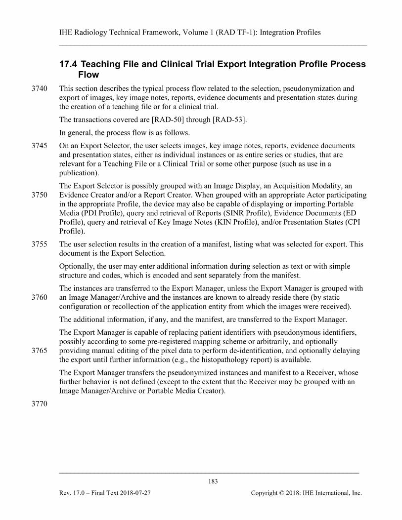
IHE Radiology Technical Framework, Volume 1 (RAD TF-1): Integration Profiles ______________________________________________________________________________
____________________________________________________________________________ 183
Rev. 17.0 – Final Text 2018-07-27 Copyright © 2018: IHE International, Inc.
17.4 Teaching File and Clinical Trial Export Integration Profile Process Flow
This section describes the typical process flow related to the selection, pseudonymization and 3740 export of images, key image notes, reports, evidence documents and presentation states during the creation of a teaching file or for a clinical trial. The transactions covered are [RAD-50] through [RAD-53]. In general, the process flow is as follows. On an Export Selector, the user selects images, key image notes, reports, evidence documents 3745 and presentation states, either as individual instances or as entire series or studies, that are relevant for a Teaching File or a Clinical Trial or some other purpose (such as use in a publication). The Export Selector is possibly grouped with an Image Display, an Acquisition Modality, an Evidence Creator and/or a Report Creator. When grouped with an appropriate Actor participating 3750 in the appropriate Profile, the device may also be capable of displaying or importing Portable Media (PDI Profile), query and retrieval of Reports (SINR Profile), Evidence Documents (ED Profile), query and retrieval of Key Image Notes (KIN Profile), and/or Presentation States (CPI Profile). The user selection results in the creation of a manifest, listing what was selected for export. This 3755 document is the Export Selection. Optionally, the user may enter additional information during selection as text or with simple structure and codes, which is encoded and sent separately from the manifest. The instances are transferred to the Export Manager, unless the Export Manager is grouped with an Image Manager/Archive and the instances are known to already reside there (by static 3760 configuration or recollection of the application entity from which the images were received). The additional information, if any, and the manifest, are transferred to the Export Manager. The Export Manager is capable of replacing patient identifiers with pseudonymous identifiers, possibly according to some pre-registered mapping scheme or arbitrarily, and optionally providing manual editing of the pixel data to perform de-identification, and optionally delaying 3765 the export until further information (e.g., the histopathology report) is available. The Export Manager transfers the pseudonymized instances and manifest to a Receiver, whose further behavior is not defined (except to the extent that the Receiver may be grouped with an Image Manager/Archive or Portable Media Creator). 3770
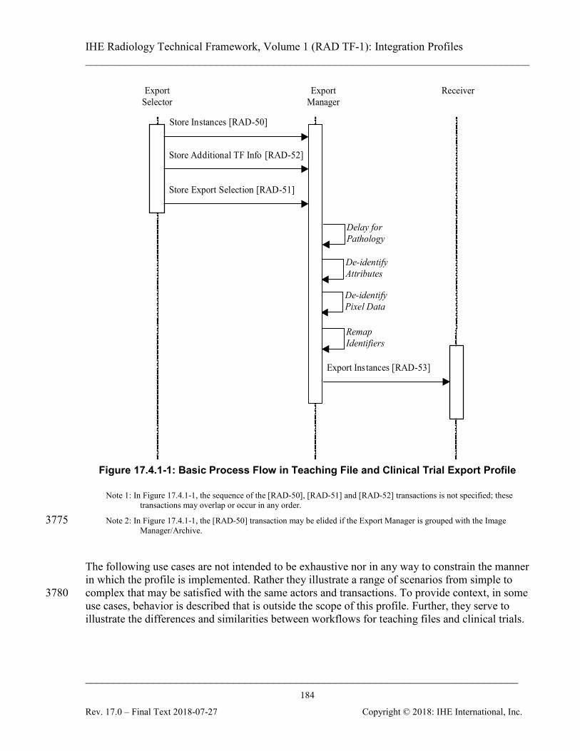
IHE Radiology Technical Framework, Volume 1 (RAD TF-1): Integration Profiles ______________________________________________________________________________
____________________________________________________________________________ 184
Rev. 17.0 – Final Text 2018-07-27 Copyright © 2018: IHE International, Inc.
De-identify Pixel Data
Store Instances [RAD-50]
Store Export Selection [RAD-51]
De-identify Attributes
Remap Identifiers
Store Additional TF Info [RAD-52]
Export Instances [RAD-53]
Export Selector
Export Manager
Receiver
Delay for Pathology
Figure 17.4.1-1: Basic Process Flow in Teaching File and Clinical Trial Export Profile
Note 1: In Figure 17.4.1-1, the sequence of the [RAD-50], [RAD-51] and [RAD-52] transactions is not specified; these transactions may overlap or occur in any order.
Note 2: In Figure 17.4.1-1, the [RAD-50] transaction may be elided if the Export Manager is grouped with the Image 3775 Manager/Archive.
The following use cases are not intended to be exhaustive nor in any way to constrain the manner in which the profile is implemented. Rather they illustrate a range of scenarios from simple to complex that may be satisfied with the same actors and transactions. To provide context, in some 3780 use cases, behavior is described that is outside the scope of this profile. Further, they serve to illustrate the differences and similarities between workflows for teaching files and clinical trials.
IHE Radiology Technical Framework, Volume 1 (RAD TF-1): Integration Profiles ______________________________________________________________________________
____________________________________________________________________________ 185
Rev. 17.0 – Final Text 2018-07-27 Copyright © 2018: IHE International, Inc.
17.4.1 Teaching File Use Cases The teaching file is a vital tool in medical education. Traditionally assembled from collections of film, teaching files now need to be constructed from digital images. Digital media enables 3785 broader dissemination of the content both within and outside the enterprise, often as federated collections that share a common query mechanism. Teaching file case authors need access to images and related information, which usually reside in the Image Archive/Manager and are viewed on an Image Display. Cases may also be identified on the Acquisition Modality. Relevant images, series or studies are often identified whilst the 3790 author is engaged in other tasks such interpretation; hence need to be flagged for later authoring. Enterprises frequently restrict access to information containing a patient’s identity on systems on which teaching files are typically authored; hence the images and related information may need to be de-identified before transfer to the authoring system. Distribution of teaching files beyond an institution always involves de-identification. 3795
17.4.1.1 Use Case 1 – Images Selected for Teaching File During Reporting, Review or Acquisition
User Actions: A radiologist is performing diagnostic reporting of possibly many studies for different patients during the course of the day. Alternatively, the radiologist is consulting on a study received from 3800 a referral patient on CD. Or, the radiologist is performing an image-guided biopsy on an acquisition device. Images from a particular patient are noted to be of special interest and potentially suitable for teaching. The radiologist selects several relevant images from the current and prior studies to be de-identified and saved to his teaching file collection. The selection may entail entire series or 3805 studies, such as when later 3D reconstruction or multi-modality fusion may be required. No additional information is entered at this time since the radiologist is busy. Sometime later, the radiologist will access his teaching file collection and use a teaching file authoring program on his personal computer to create a multi-media teaching file. The manner in which the teaching file is authored and distributed is beyond the scope of this profile. 3810 The transfer to the radiologist’s teaching file collection may take place either over the network or on media (the latter case might be applicable if the radiologist is a locum or from an outside facility or if the clinical and teaching networks are not connected).
Implementation: The radiologist is viewing images on an Image Display grouped with an Export Selector. The 3815 Image Display is also participating in the Portable Data for Imaging Profile in the case of the review of the referral CD. Or, the radiologist is working on an Acquisition Modality grouped with an Export Selector. The Export Selector allows one or more images from current and prior studies to be selected, and then to be “exported for teaching”. 3820

IHE Radiology Technical Framework, Volume 1 (RAD TF-1): Integration Profiles ______________________________________________________________________________
____________________________________________________________________________ 186
Rev. 17.0 – Final Text 2018-07-27 Copyright © 2018: IHE International, Inc.
The Export Selector may be preconfigured to know that the images are already stored on an Image Manager/Archive with which the Export Manager is grouped; in such a case no Store Instances [RAD-50] transactions are required. In the media case, Store Instances [RAD-50] transactions would be required. The user action triggers a Store Export Selection [RAD-51] transaction to the Export Manager. 3825 The manifest is encoded as a Key Object Selection document with a Document Title of “For Teaching File Export”. When entire series or studies have been selected, the manifest will enumerate all the instances from all the selected series and studies. There may be multiple different teaching file “folders” to which the case might be added. To allow the user to identify which teaching file the images are intended for, a free text field or a 3830 pre-configured pull down list is provided, which is encoded as the disposition in the text value of the Key Object Selection document. No additional content was entered at the time of selection, so no Store Additional Teaching File Information [RAD-52] transaction is sent. If the Export Manager is not grouped with an Image Manager/Archive that already has the 3835 images, upon receiving the images via the Store Instances [RAD-50] transaction, the Export Manager stores them internally. When the Export Manager receives the Store Export Selection [RAD-51] transaction, and all the images referenced therein are available, the collection is queued for pseudonymization and export. 3840 The Export Manager automatically removes all patient identification from the image attributes as well as other text and private attributes (according to a pre-configured set of rules), checks to be sure that the SOP Class of the image is not one likely to contain burned-in identification in the pixel data, and inserts new dummy patient identification and other text attributes so as not to invalidate compliance of the instance with the IOD. Note that the extent of de-identification is 3845 configurable, and if de-identification is to be performed in the teaching file authoring system later, may not be performed by the Export Manager at all. This may be the case when the patient’s identity is required by teaching file authoring system to allow the user to search for other clinical and historical information. If the Export Manager supports the De-identify Pixel Data Option, any of the images likely to 3850 contain burned in identification information in the pixel data are placed on an internal work list for a human operator to check and if necessary edit the pixel data to remove the burned in identification, before the images are forwarded to the Receiver. The Export Manager then sends the pseudonymized DICOM images and an updated Key Object Selection document containing the manifest referencing the new identifiers and UIDs to the 3855 appropriate Receiver using an Export Instances [RAD-53] transaction. The Receiver may be the enterprise’s central teaching file authoring system. Upon receiving the images and the manifest, it extracts the identity of the radiologist who created the manifest from the Person Observer Identifying Attribute template encoded within the Key Object Selection
IHE Radiology Technical Framework, Volume 1 (RAD TF-1): Integration Profiles ______________________________________________________________________________
____________________________________________________________________________ 187
Rev. 17.0 – Final Text 2018-07-27 Copyright © 2018: IHE International, Inc.
document. It uses this identity, or the disposition information, to route the case to that user’s 3860 folder of pending cases for authoring. The Receiver could be grouped with a Portable Media Creator, in which case the images and manifest could be burned to an IHE PDI CD. Note that the behavior of the Receiver is described only to illustrate the use case, and is beyond the scope of this profile.
17.4.1.2 Use Case 2 – Complete Teaching File Authoring During Reporting with 3865 Multiple Instance Types and Multiple Export Targets
User Actions: A radiologist is performing diagnostic reporting. Images from a particular patient are noted to be of special interest and potentially suitable for teaching. In addition to having the clinical report for the current case that has just been created, the radiologist has also queried for prior reports, 3870 extracted a surgical pathology report from an external report repository, and had evidence documents previously created by a quantitative analysis package running on the acquisition device. The radiologist selects several relevant images from the current and prior studies, saves presentation states containing the appropriate windows and annotations of interesting lesions, as well as several evidence documents and the surgical pathology report, and decides to create a 3875 teaching file. The workstation then prompts the radiologist to enter additional information according to a pre-defined template of headings and plain text sections, including history, organ system, anatomy, findings, differential diagnosis and final diagnosis. The radiologist uses the workstation’s text editing capability to cut and paste from the various reports into the template, as well as selecting 3880 organ system, anatomy and diagnoses from pick-lists of codes. Upon completion, the user instructs the workstation to release the case, which is then made available throughout the enterprise on the PACS and electronic medical record systems with a pseudonymous identification in the departmental teaching collection folder, as well as via the web both inside and outside the enterprise. 3885
Implementation: The radiologist is viewing images on an Image Display grouped with an Export Selector, as well as an Evidence Creator, Report Creator and Report Reader. It participates in the Evidence Document and Simple Image and Numeric Report Profiles and hence has access to Evidence Documents and Reports, as well as an External Report Repository. It is also participating in the 3890 Consistent Presentation of Images Profile hence supports the creation and retrieval of Presentation States. The Export Selector supports the Additional Teaching File Information Option. The Export Selector allows one or more images, reports, evidence documents or presentation states from current and prior studies to be selected, and then to be “exported for teaching”, 3895 together with the additional information.
IHE Radiology Technical Framework, Volume 1 (RAD TF-1): Integration Profiles ______________________________________________________________________________
____________________________________________________________________________ 188
Rev. 17.0 – Final Text 2018-07-27 Copyright © 2018: IHE International, Inc.
The user action triggers Store Instances [RAD-50] transactions, Store Additional Teaching File Information [RAD-52] transactions and multiple Store Export Selection [RAD-51] transactions to the Export Manager (one for each Receiver). The manifest is encoded as a Key Object Selection document. The additional information is 3900 encoded as a Structured Report according to a pre-defined template. The Export Manager de-identifies and re-identifies the image, reports, evidence documents, presentation states and additional information with pseudonymous values as in Use Case 1. The Export Manager then sends the pseudonymized DICOM instances, the pseudonymized additional information, and an updated Key Object Selection document containing the manifest 3905 referencing the new identifiers and UIDs to the appropriate Receivers using Export Instances [RAD-53] transactions. The multiple Receivers in this use case include the Image Managers and Archives for the clinical PACS and the Electronic Medical Record Systems, as well as a Receiver that is the enterprise’s own web-based teaching file distribution system, and another Receiver that is a portal to a central 3910 repository of teaching files operated by the parent academic institution.
17.4.1.3 Use Case 3 – Images Selected for Teaching File During Reporting with Delayed Export Awaiting Pathology
User Actions: A radiologist is performing diagnostic reporting. Images from a particular patient are noted to be 3915 of special interest and potentially suitable for teaching. The radiologist selects several relevant images from the current study to be de-identified and saved to his teaching file collection. However, the teaching file case cannot be authored until the pathology report is available. Accordingly, during selection the radiologist chooses the “delay for histopathology report” modifier to the “export for teaching” action. 3920
Implementation: The implementation proceeds as in Use Case 1. The Key Object Selection document, in addition to having a Document Title that indicates that the case is for teaching file export, also has a coded Concept Modifier indicating “Delay for histopathology report”. 3925 When the Export Manager receives the Store Export Selection [RAD-51] transaction, and all the images referenced therein are available, the collection is queued. However, since the Export Manager supports the Delay for Reason Option, pre-configured rules within the Export Manager Actor triggered by the “Delay for Reason” modifier indicate that the device should wait until it receives a (relevant) histopathology report for the patient, before de-identifying and 3930 pseudonymizing the images and the histopathology report and forwarding them to the Receiver. The manner in which the Export Manager receives the histopathology report is undefined and outside the scope of this profile, but it must be re-encoded in a DICOM Structured Report

IHE Radiology Technical Framework, Volume 1 (RAD TF-1): Integration Profiles ______________________________________________________________________________
____________________________________________________________________________ 189
Rev. 17.0 – Final Text 2018-07-27 Copyright © 2018: IHE International, Inc.
(perhaps as plain text) for export to the Receiver, and a reference to it included in a revised manifest. 3935
17.4.2 Clinical Trial Use Cases Clinical trials have similar needs to teaching files, in that images and related information need to be selected for export to other systems, and other organizations in the case of multi-center trials. During export, images need to be de-identified and trial-specific identifiers inserted in accordance with local or national policy and the rules of the trial protocol. 3940 The following use cases serve to illustrate the differences and similarities between workflows for teaching files and clinical trials.
17.4.2.1 Use Case 4 – Series or Studies Selected for Clinical Trial from Referring User’s Workstation or Acquisition Modality
User Actions: 3945 A patient enrolled in a multi-center clinical trial undergoes an examination, the images of which require review by a central facility. Though the patient has given their informed consent to release their identification (PHI) to the central facility, site policy dictates that the images be de-identified first regardless. The managers of the trial supply replacement identifiers to be used. A technologist, nurse or physician participating in the trial uses a referring user’s workstation on 3950 the PACS to select the relevant studies, or selected series from the study, for export to the central facility. Alternatively, the technologist performing a study uses the acquisition device to select the relevant study, or selected series from the study, for export to the central facility.
Implementation: 3955 In this case, the user is viewing images on an Image Display or Acquisition Modality grouped with an Export Selector. The Export Selector allows images, series and studies to be selected, and then to be “exported for clinical trial”. The user action triggers the Export Selector to send images and an Export Selection to the Export Manager as in Use Case 1, except that the Document Title of the Key Object Selection document 3960 specifies “For Clinical Trial Export” instead of “For Teaching File Export”, and there is no Additional Teaching File Information transaction. There may be multiple trials in progress, and a single patient may be a participant in more than one trial, hence to allow the user to identify which clinical trial the images are intended for, a free text field or a pre-configured pull down list is provided, which is encoded as the disposition 3965 in the text value of the Key Object Selection document. The Export Manager de-identifies and re-identifies the image, reports, evidence documents, presentation states and additional information with pseudonymous values as in Use Case 1, except that the Export Manager supports the Remap Identifiers Option. In order to pseudonymize the images with the trial-specific identifiers, both as replacements for the conventional patient 3970
IHE Radiology Technical Framework, Volume 1 (RAD TF-1): Integration Profiles ______________________________________________________________________________
____________________________________________________________________________ 190
Rev. 17.0 – Final Text 2018-07-27 Copyright © 2018: IHE International, Inc.
identification attributes and to populate the clinical trial specific attributes, the Export Manager Actor contains a pre-configured mapping of Patient to Subject identifiers (usually referred to as a subject enrollment list). The Export Manager inserts replacement patient identification and clinical trials attributes obtained from its mapping table. The Export Manager Actor then sends the pseudonymized DICOM images and an updated 3975 manifest to a Receiver as in Use Case 1. Which Receiver to send to may be pre-configured or may vary depending on the disposition text value of the manifest. The Receiver may be the system responsible for transferring the images to the central review facility. For privacy and security considerations, typically it will use a secure Internet channel, such as a VPN, TLS (SSL) or SSH tunnel. The security mechanism is beyond the scope of this 3980 profile. Or, the Receiver could be grouped with a Portable Media Creator, as described in Use Case 1, in which case CDs would be burned and mailed to the central review facility. This use case is distinguished from the teaching file use cases in that:
• Selection is usually at the study or series level, and rarely at the image level 3985
• A mapping to pre-defined replacement identifiers is defined in the Export Manager
• The Export Manager also inserts clinical trial specific attributes
• A means of routing the images to the appropriate trial is required In other respects, this use case is fundamentally the same as Use Case 1.
17.4.3 Research Collection Use Cases 3990 The selection of instances or entire studies for research purposes shares many similarities with use cases for teaching files and clinical trials. The studies generally remain in circulation for clinical use, as well as being “copied” into separate “folders” in the clinical Image Manager/Archive or copied to a separate research Image Manager/Archive. De-identification may not be required for local research collections, but for those maintained centrally (outside the 3995 enterprise), remapping of identifiers to predefined pseudonyms is often required. A specific Document Title of “For Research Collection Export” is provided for such use cases, which are otherwise no different from the foregoing teaching file and clinical trial use cases in terms of user actions, actors or sequencing of transactions.
17.4.4 Publication Authoring Use Cases 4000 The selection of instances for use in a publication shares many similarities with use cases for teaching files. De-identification of the DICOM Header and the pixel data is required. The disposition for these use cases should reference the target author of the selected instances. A specific Document Title of “For Publication Export” (TCE008) is provided for such use cases, which are otherwise no different from the foregoing teaching use cases in terms of user actions, 4005 actors or sequencing of transactions. This use case is supported by the process flow shown in Figure 17.4.1-1.
IHE Radiology Technical Framework, Volume 1 (RAD TF-1): Integration Profiles ______________________________________________________________________________
____________________________________________________________________________ 191
Rev. 17.0 – Final Text 2018-07-27 Copyright © 2018: IHE International, Inc.
18 Cross-Enterprise Document Sharing for Imaging (XDS-I.b) Integration Profile
IMPORTANT NOTE: The Cross-Enterprise Document Sharing for Imaging (XDS-I) 4010 Integration Profile (originally found here) has been deprecated and is replaced by a functionally equivalent profile called Cross-Enterprise Document Sharing for Imaging (XDS-I.b), which is described in the remainder of this section. The Cross-Enterprise Document Sharing (XDS.b) Profile in the IHE IT Infrastructure Domain provides a solution for sharing (publishing, finding and retrieving) documents across a group of 4015 affiliated enterprises. The XDS for Imaging (XDS-I.b) Profile, defined here, extends and specializes the mechanisms defined by XDS.b to support imaging “documents”, specifically including the following:
• Imaging studies that include images acquired on a broad range of different modalities, as well as evidence documents (e.g., post-processing measurements/analysis outcome), and 4020 presentation states.
• Diagnostic reports resulting from the interpretation of one or more related imaging studies provided in a ready-for-display form
• A selection of diagnostically significant images associated with the report content. These document types along with the actor capabilities required to share them are defined by this 4025 profile. Since the XDS for Imaging (XDS-I.b) Profile depends on and extends the IT Infrastructure XDS.b Profile including the use of terms defined in XDS.b (e.g., XDS Affinity Domain, submission set, etc.) the reader of XDS-I.b is expected to have read and understood the XDS Profiles (See ITI TF-1: 10). The XDS-I.b specification does not repeat requirements and text for 4030 the XDS-defined Actors Document Repository, Document Registry, and Document Consumer, and does not place any new requirements on these actors. Both the XDS.b and XDS for Imaging (XDS-I.b) Integration Profiles are not intended to address all cross-enterprise EHR communication needs. Many scenarios may require the use of other IHE Integration Profiles, such as Patient Identifier Cross-Referencing (PIX), Audit Trail and 4035 Node Authentication (ATNA), Enterprise User Authentication (EUA), Cross-Enterprise User Authentication (XUA) and Retrieve Information for Display (RID). Other scenarios may be only partially supported, while still others may require future IHE Integration Profiles, which will be defined by IHE as soon as the necessary base standards are available. Specifically:
1. The operation of any XDS Affinity Domain will require that a proper security model be 4040 put in place. It is expected that a range of security models should be possible. Although the XDS-I.b Integration Profile is not intended to include nor require any specific security model, it is required that XDS-I.b implementers shall group XDS-I.b actors with actors from the IHE Audit Trail and Node Authentication and will need an Access Control capability that operates in such a cross-enterprise environment. New IHE Integration 4045 Profiles have been identified as candidates (e.g., Public Key Infrastructure, Access
IHE Radiology Technical Framework, Volume 1 (RAD TF-1): Integration Profiles ______________________________________________________________________________
____________________________________________________________________________ 192
Rev. 17.0 – Final Text 2018-07-27 Copyright © 2018: IHE International, Inc.
Control, etc.). There is a discussion of XDS-I.b security considerations in RAD TF-1: Appendix H.
2. XDS and XDS-I.b do not address transactions for the management or configuration of an XDS Affinity Domain. For example, the configuration of network addresses or the 4050 definition of what type of clinical information is to be shared is specifically left up to the policies established by the XDS Affinity Domain.
3. XDS and XDS-I.b do not specifically address the patient information reconciliation process necessary between the XDS Affinity Domain and any other local patient identity domains that Document Sources and Document Consumers may be members of. For a 4055 discussion of some of these issues see RAD TF-1: Appendix G.
4. XDS and XDS-I.b do not directly address the rendering and display of the documents retrieved by the Document and Imaging Document Consumers. Users wishing to achieve a well-defined level of display/ rendering capability simply need to request systems that combine the XDS-I.b Imaging Document Consumer Actor with an Image Display Actor 4060 from the appropriate Profile (e.g., Mammography Image, NM Image, Basic Image Review, etc.).
5. XDS and XDS-I.b do not directly address the rendering and display of the documents retrieved by the Document and Imaging Document Consumers. Users wishing to achieve a well-defined level of display/ rendering capability simply need to request systems that 4065 combine the XDS-I.b Imaging Document Consumer Actor with an Image Display Actor from the appropriate Profile (e.g., Mammography Image, NM Image, Basic Image Review, etc.).
18.1 Actors/ Transactions Figure 18.1-1 shows the actors directly involved in this profile and the transactions between 4070 actors. The shaded XDS actors are NOT actually included in this profile but are included to show the other endpoint of transactions that ARE part of the profile (e.g., the Document Repository Actor that is the endpoint for the Provide and Register Imaging Document Set – MTOM/XOP Transaction). As a result, the shaded actors are not listed in Table 18.1-1. The XDS-I.b Profile does not place any additional requirements on any of these actors above and beyond what it 4075 required of them by the ITI XDS.b Profile.
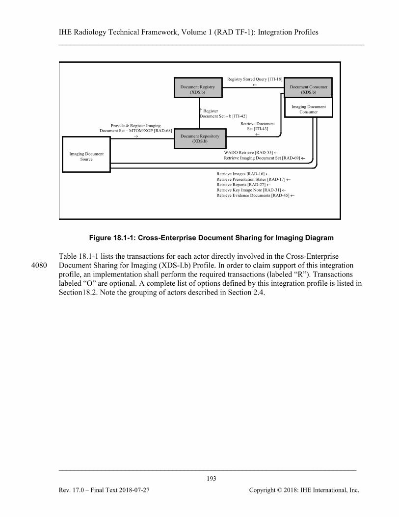
IHE Radiology Technical Framework, Volume 1 (RAD TF-1): Integration Profiles ______________________________________________________________________________
____________________________________________________________________________ 193
Rev. 17.0 – Final Text 2018-07-27 Copyright © 2018: IHE International, Inc.
Imaging Document
Source
Document Consumer
(XDS.b)
Document Registry
(XDS.b)
Document Repository (XDS.b)
Provide & Register Imaging Document Set – MTOM/XOP [RAD-68]
→
↑ Register Document Set – b [ITI-42]
Retrieve Document Set [ITI-43]
←
Registry Stored Query [ITI-18] ←
WADO Retrieve [RAD-55] ← Retrieve Imaging Document Set [RAD-69] ←
Retrieve Images [RAD-16] ← Retrieve Presentation States [RAD-17] ← Retrieve Reports [RAD-27] ← Retrieve Key Image Note [RAD-31] ← Retrieve Evidence Documents [RAD-45] ←
Imaging Document
Consumer
Figure 18.1-1: Cross-Enterprise Document Sharing for Imaging Diagram
Table 18.1-1 lists the transactions for each actor directly involved in the Cross-Enterprise Document Sharing for Imaging (XDS-I.b) Profile. In order to claim support of this integration 4080 profile, an implementation shall perform the required transactions (labeled “R”). Transactions labeled “O” are optional. A complete list of options defined by this integration profile is listed in Section18.2. Note the grouping of actors described in Section 2.4.
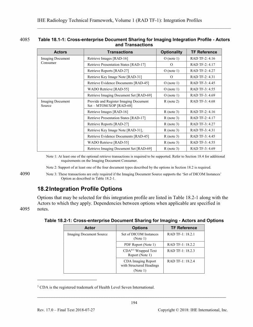
IHE Radiology Technical Framework, Volume 1 (RAD TF-1): Integration Profiles ______________________________________________________________________________
____________________________________________________________________________ 194
Rev. 17.0 – Final Text 2018-07-27 Copyright © 2018: IHE International, Inc.
Table 18.1-1: Cross-enterprise Document Sharing for Imaging Integration Profile - Actors 4085 and Transactions
Actors Transactions Optionality TF Reference Imaging Document Consumer
Retrieve Images [RAD-16] O (note 1) RAD TF-2: 4.16 Retrieve Presentation States [RAD-17] O RAD TF-2: 4.17 Retrieve Reports [RAD-27] O (note 1) RAD TF-2: 4.27 Retrieve Key Image Note [RAD-31] O RAD TF-2: 4.31 Retrieve Evidence Documents [RAD-45] O (note 1) RAD TF-3: 4.45 WADO Retrieve [RAD-55] O (note 1) RAD TF-3: 4.55 Retrieve Imaging Document Set [RAD-69] O (note 1) RAD TF-3: 4.69
Imaging Document Source
Provide and Register Imaging Document Set – MTOM/XOP [RAD-68]
R (note 2) RAD TF-3: 4.68
Retrieve Images [RAD-16] R (note 3) RAD TF-2: 4.16 Retrieve Presentation States [RAD-17] R (note 3) RAD TF-2: 4.17 Retrieve Reports [RAD-27] R (note 3) RAD TF-3: 4.27 Retrieve Key Image Note [RAD-31], R (note 3) RAD TF-3: 4.31 Retrieve Evidence Documents [RAD-45] R (note 3) RAD TF-3: 4.45 WADO Retrieve [RAD-55] R (note 3) RAD TF-3: 4.55 Retrieve Imaging Document Set [RAD-69] R (note 3) RAD TF-3: 4.69
Note 1: At least one of the optional retrieve transactions is required to be supported. Refer to Section 18.4 for additional requirements on the Imaging Document Consumer.
Note 2: Support of at least one of the four document types described by the options in Section 18.2 is required.
Note 3: These transactions are only required if the Imaging Document Source supports the ‘Set of DICOM Instances’ 4090 Option as described in Table 18.2-1.
18.2 Integration Profile Options Options that may be selected for this integration profile are listed in Table 18.2-1 along with the Actors to which they apply. Dependencies between options when applicable are specified in notes. 4095
Table 18.2-1: Cross-enterprise Document Sharing for Imaging - Actors and Options Actor Options TF Reference
Imaging Document Source Set of DICOM Instances (Note 1)
RAD TF-1: 18.2.1
PDF Report (Note 1) RAD TF-1: 18.2.2 CDA®3 Wrapped Text
Report (Note 1) RAD TF-1: 18.2.3
CDA Imaging Report with Structured Headings
(Note 1)
RAD TF-1: 18.2.4
3 CDA is the registered trademark of Health Level Seven International.
IHE Radiology Technical Framework, Volume 1 (RAD TF-1): Integration Profiles ______________________________________________________________________________
____________________________________________________________________________ 195
Rev. 17.0 – Final Text 2018-07-27 Copyright © 2018: IHE International, Inc.
Actor Options TF Reference Imaging Document Consumer No options defined -
Note 1: At least one of these four options is required
18.2.1 Set of DICOM Instances Option This option requires the Imaging Document Source to create a DICOM manifest that references 4100 DICOM instances, and to provide and register this document to the Document Repository. The Imaging Document Source is required to ensure that the referenced images from within a published manifest are available to be retrieved. For details of the transaction affected by this option, refer to RAD TF-3: 4.68.4.1.2.1.
18.2.2 PDF Report Option 4105 This option requires the Imaging Document Source to provide and register an Imaging Report in a PDF format to the Document Repository. The published report may contain embedded images or pre-computed links that reference images in a non-DICOM format. The Imaging Document Source is required to ensure that image references are valid links. For details of the transaction affected by this option, refer to RAD TF-3: 4.68.4.1.2.2. 4110
18.2.3 CDA Wrapped Text Report Option This option requires the Imaging Document Source to send to the Document Repository a CDA R2 document containing a Text Report. For details, refer to RAD TF-3: 4.68.4.1.2.2.
18.2.4 CDA Imaging Report with Structured Headings Option This option requires the Imaging Document Source to send to the Document Repository a CDA 4115 R2 document containing an Imaging Report with Structured Headings. For details, refer to RAD TF-3: 4.68.4.1.2.2.
18.3 Image Information Sharing Process Flow The sharing of imaging related information among different health professionals and facilities, even across administrative and geographic boundaries can lead to a large variety of information 4120 flows. Typical imaging information sets used in healthcare settings are well known, but the challenge is to distill the “exchange” scenarios to drive the sharing of imaging information across enterprises distributed over a community, region or nation.
18.3.1 Overview of Imaging Information Sharing Use Cases The following use case scenarios express the core imaging information sharing common to most 4125 clinical settings. They cover:
1. Routine imaging referral. The referring physician in his office requests that a patient have an examination done at an imaging facility. The physician expects to have electronic
IHE Radiology Technical Framework, Volume 1 (RAD TF-1): Integration Profiles ______________________________________________________________________________
____________________________________________________________________________ 196
Rev. 17.0 – Final Text 2018-07-27 Copyright © 2018: IHE International, Inc.
access to the imaging report and to the images if needed after the examination has been performed on his patient. This use case is further analyzed in this profile. 4130
2. Course of Treatment Consult. An emergency physician orders an imaging examination for a patient at his hospital. After reviewing the preliminary report the ER physician decides to consult a surgical specialist at the regional hospital for advice on a course of action. For this, the surgical specialist accesses the images and preliminary report and reviews them in order to propose, on the phone, a course of action for the patient. This 4135 use case is further analyzed in this profile.
3. Clinical Consult. A general practitioner performs a routine imaging referral, reviews the shared imaging report and chooses to send the patient for evaluation by a specialist (e.g., an oncologist). The specialist needs access to the imaging report and full image set produced at the imaging facility where the patient had been sent by his general 4140 practitioner to perform the examination. This use case is further analyzed in this profile.
4. General imaging record access. A patient relocates or decides to change her physician. The new physician needs to retrieve relevant information from the patient record, review its content, including recent labs and imaging studies. A similar situation occurs when a patient is admitted for an emergency and timely access to the patient’s past information is 4145 required, including prior imaging studies. This use case is further analyzed in this profile.
This profile describes the information sharing transactions for care-delivering systems to publish patient’s imaging diagnostic documents (EHR-CR) for sharing across enterprises as longitudinal patient care records (HER-LR). The policies or administrative details regarding the sharing of imaging information are for the most part not explicitly discussed so as not to obscure clinical 4150 needs. Administrative variations between countries and regions are expected, and can be added or modified without losing the clinical information-sharing context. Since the focus is on the sharing and access to patients imaging records rather than the entire workflow in which such information sharing takes place, other activities are described as though they are being done by telephone, paper mail, fax, etc. In an integrated electronic environment 4155 these other activities may be more automated, but those details are separate from the records access/sharing and are to be addressed by separate integration profiles.
18.3.2 Assumptions The imaging information needs to be shared between multiple care delivery organizations (information sources and consumers), each (typically) with its own RIS and PACS. The point of 4160 service (“POS”) for physicians may be supported by a variety of systems: hospital EMR, physician practice system, PACS viewers, EHR web application, etc. The concept of sharing information across enterprises that have agreed to join in such a health information network is based on basic design principles that can be summarized in the following points: 4165
IHE Radiology Technical Framework, Volume 1 (RAD TF-1): Integration Profiles ______________________________________________________________________________
____________________________________________________________________________ 197
Rev. 17.0 – Final Text 2018-07-27 Copyright © 2018: IHE International, Inc.
1. A group of healthcare enterprises have agreed to work together using a common set of policies and to share a common infrastructure of repositories and a registry for an affinity domain.
2. Information sources (e.g., EHR, lab system, PACS) select the “documents” they wish to share. 4170
3. Documents may include any information in an agreed format (e.g., a PDF document, a DICOM manifest, etc.). Documents are stored in multiple document repositories.
4. Shared documents are registered with a central service called a document registry that tracks only indexing information and the location from which documents may be retrieved. 4175
5. Information consumers may query this well-defined unique/singular indexing service (document registry) to find the document index information for any patient and the location from which documents may be retrieved (document repositories).
6. Information sources remain the owner of the documents shared in repositories and, thereby, remain responsible for replacing or deprecating its documents if necessary. 4180
In each one of the use cases, it is assumed that the people and the information systems that participate in a single “Affinity Domain” have agreed upon mechanisms to address:
• Governance: operational structure, data stewardship, etc.
• Privacy: consent management and data masking controls
• Security: Authorization and authentication, network security, audit trails, etc. 4185
• Normalized patient ID schemes: MPI (Master Patient Index), unique information IDs, etc.
• Coded Vocabularies used for registry information
18.3.3 Use cases
18.3.3.1 Routine Imaging Referral Use Case This scenario describes imaging information sharing in a typical patient referral and reporting 4190 use case where:
• An examination is performed upon the request of a referring physician:
• The referring physician accesses the regional health information network and reviews the report along with the key images and may optionally access the full image set that made the study. 4195
This scenario is characterized by all the information being provided for sharing at one time, as a single logical unit, when the imaging study is completed by the radiology enterprise (i.e., a single “document submission set”).
IHE Radiology Technical Framework, Volume 1 (RAD TF-1): Integration Profiles ______________________________________________________________________________
____________________________________________________________________________ 198
Rev. 17.0 – Final Text 2018-07-27 Copyright © 2018: IHE International, Inc.
18.3.3.1.1 Process Flow Figure 18.3.3-1 highlights the people and systems participating in this regional health 4200 information network, including:
• Physician Office: A referring physician working out of a private office with a physician practice system for access to information
• RIS/PACS Enterprise A: A radiology enterprise with modality equipment and a RIS/PACS to manage report and imaging information: Radiology Enterprise A 4205
• RIS/PACS Enterprise B: Another radiology enterprise with a RIS/PACS to manage report and imaging information: Radiology Enterprise B
• Document Registry: A document registry that serves as the information index for the regional health information network
In the process flow description, steps that pertain to information sharing are shown in bold (and 4210 numbered). In contrast, the steps that do not pertain to the focus of information sharing are shown in italic (and not numbered). These steps are expressed to ensure a more complete context. Figure 18.3.3-2 shows the transaction diagram for this process flow. 4215 Exam is ordered The Referring Physician orders the examination and the patient goes to the Imaging Department: Radiology Enterprise A. This is well-understood workflow that may be executed using any combination of paper, faxes, telephone, and electronic communications. It may or may not be addressed using the IHE 4220 Scheduled Workflow Integration Profile. Although this step is part of the use case, it is peripheral to the specific steps for sharing of imaging of information. Step 1: Obtain Relevant Prior Imaging Information
• The PACS at Radiology Enterprise A, where the acquisition and reporting is performed, 4225 does a query of the Document Registry to identify relevant prior images and reports. It should be noted that the determination of what is relevant is the responsibility of the consumer and not the registry.
• The PACS at Radiology Enterprise A retrieves prior imaging information from a repository in another radiology enterprise within the regional health network: Radiology 4230 Enterprise B, in preparation for study acquisition and subsequent reporting
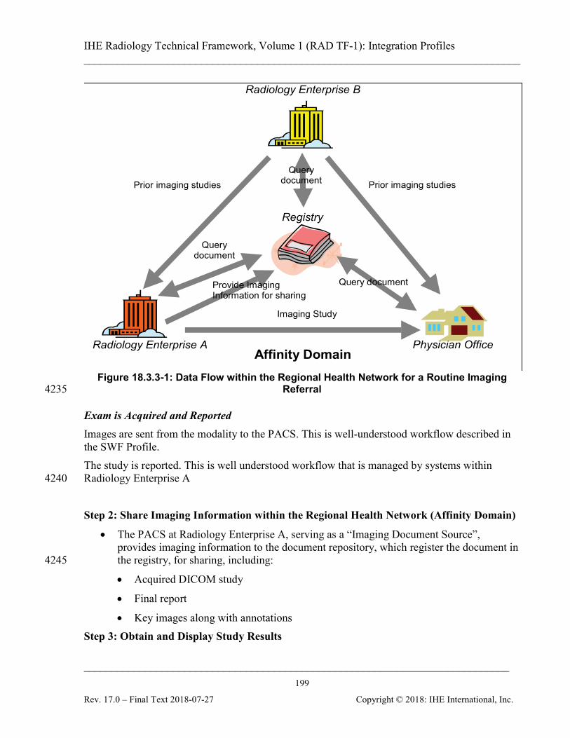
IHE Radiology Technical Framework, Volume 1 (RAD TF-1): Integration Profiles ______________________________________________________________________________
____________________________________________________________________________ 199
Rev. 17.0 – Final Text 2018-07-27 Copyright © 2018: IHE International, Inc.
Radiology Enterprise A
Radiology Enterprise B
Physician Office
Prior imaging studies
Query document
Affinity Domain
Registry
Query document
Imaging Study
Provide Imaging Information for sharing
Prior imaging studies Query
document
Figure 18.3.3-1: Data Flow within the Regional Health Network for a Routine Imaging Referral 4235
Exam is Acquired and Reported Images are sent from the modality to the PACS. This is well-understood workflow described in the SWF Profile. The study is reported. This is well understood workflow that is managed by systems within Radiology Enterprise A 4240 Step 2: Share Imaging Information within the Regional Health Network (Affinity Domain)
• The PACS at Radiology Enterprise A, serving as a “Imaging Document Source”, provides imaging information to the document repository, which register the document in the registry, for sharing, including: 4245
• Acquired DICOM study
• Final report
• Key images along with annotations Step 3: Obtain and Display Study Results
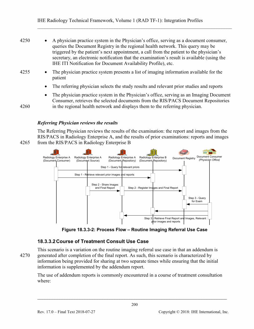
IHE Radiology Technical Framework, Volume 1 (RAD TF-1): Integration Profiles ______________________________________________________________________________
____________________________________________________________________________ 200
Rev. 17.0 – Final Text 2018-07-27 Copyright © 2018: IHE International, Inc.
• A physician practice system in the Physician’s office, serving as a document consumer, 4250 queries the Document Registry in the regional health network. This query may be triggered by the patient’s next appointment, a call from the patient to the physician’s secretary, an electronic notification that the examination’s result is available (using the IHE ITI Notification for Document Availability Profile), etc.
• The physician practice system presents a list of imaging information available for the 4255 patient
• The referring physician selects the study results and relevant prior studies and reports
• The physician practice system in the Physician’s office, serving as an Imaging Document Consumer, retrieves the selected documents from the RIS/PACS Document Repositories in the regional health network and displays them to the referring physician. 4260
Referring Physician reviews the results The Referring Physician reviews the results of the examination: the report and images from the RIS/PACS in Radiology Enterprise A, and the results of prior examinations: reports and images from the RIS/PACS in Radiology Enterprise B 4265
Radiology Enterprise A(Document Repository)
Document RegistryRadiology Enterprise A(Document Consumer)
Radiology Enterprise A(Document Source)
Step 1 - Query for relevant priors
Step 1 - Retrieve relevant prior images and reports
Step 2 - Share Imagesand Final Report Step 2 - Register Images and Final Report
Document Consumer(Physician Office)
Step 3 - Queryfor Exam
Radiology Enterprise B(Document Repository)
Step 3 - Retrieve Final Report and Images, Relevantprior images and reports
Figure 18.3.3-2: Process Flow – Routine Imaging Referral Use Case
18.3.3.2 Course of Treatment Consult Use Case This scenario is a variation on the routine imaging referral use case in that an addendum is generated after completion of the final report. As such, this scenario is characterized by 4270 information being provided for sharing at two separate times while ensuring that the initial information is supplemented by the addendum report. The use of addendum reports is commonly encountered in a course of treatment consultation where:

IHE Radiology Technical Framework, Volume 1 (RAD TF-1): Integration Profiles ______________________________________________________________________________
____________________________________________________________________________ 201
Rev. 17.0 – Final Text 2018-07-27 Copyright © 2018: IHE International, Inc.
• An ER physician orders an exam, and the study is acquired in the affiliated radiology 4275 department.
• A department radiologist creates and shares a report as well as identifies key images and annotations.
• A remotely located surgical specialist, at the request of the ER physician, reviews the report along with key images and the full study, and provides a consult to the ER 4280 physician (this use case does not constrain the method for communicating the results of the consult, e.g., phone, fax, etc.).
• The radiologist identifies additional information and completes an addendum to the initial report.
Note that the scenario where the radiologist seeks an opinion from a more senior radiologist is 4285 similar to this use case.
18.3.3.2.1 Process Flow The process flow description and steps are as for the routine imaging referral, but with the following variations (shown in bold): Exam is ordered 4290 Step 1: Obtain Relevant Prior Imaging Information Exam Acquisition and Reporting Step 2: Share Imaging Information within the Regional Health Network (Affinity Domain)
• The PACS at Enterprise A, serving as a “Imaging Document Source”, provides imaging information to the document repository, which register the document in the registry, for 4295 sharing, including:
• Acquired DICOM study
• Report
• Key images along with annotations Step 3: Obtain and Display Study Results 4300 ER Physician reviews the results Step 4: Share Addendum to Report within the Regional Health Network (Affinity Domain)
• Sometime later on, the radiologist creates an addendum to the initial report. This addendum is transcribed into the RIS at Enterprise A and signed off by the radiologist. This addendum must now supplement the initial report. 4305
• The RIS at Enterprise A performs a document query of the document registry for the first submission set.

IHE Radiology Technical Framework, Volume 1 (RAD TF-1): Integration Profiles ______________________________________________________________________________
____________________________________________________________________________ 202
Rev. 17.0 – Final Text 2018-07-27 Copyright © 2018: IHE International, Inc.
• The RIS at Enterprise A, serving as a “Imaging Document Source”, provides the addendum for sharing to the document registry including the content of the first submission set and declaring the new document as an addendum to the initial report. 4310
Figure 18.3.3-3 shows the transaction diagram for this process flow.
Orthopaedic Centre(Document Consumer)
Rad. Enterprise A(Document Repository) Document RegistryRad. Enterprise A
(Document Consumer)Rad. Enterprise A: PACS
(Document Source)Rad. Enterprise A: RIS
(Document Source)
Step 1 - Query or relevant prior exams
Step 1 - Retrieve relevant prior images and reports
Step 2 - Share images and Initial Report(Submission Set 1) Step 2 - Register images and report
Step 3 - Query forexam
Step 3 - Retrieve images and report for new exam
Step 4 - ShareAddendum
(Submission Set 2)
Step 4 - Register Addendum
Step 4 - Query for new exam (associated submission set)
Rad. Enterprise B(Document Repository)
Figure 18.3.3-3: Process Flow – Course of Treatment Consult Use Case
18.3.3.3 Clinical Consult Use Case 4315 This scenario is an extension of the routine imaging referral use case in that a consult report is generated based from the original imaging exam and radiologist report. As such, this scenario is characterized by information being provided for sharing at two separate times by two separate source systems. The reports shared in this use case are based on the same initial imaging exam. However the 4320 reports are generated by different people and registered by different systems. The generation of consult reports is commonly encountered in cancer treatment. As such, the following clinical consult use case is used to describe the scenario:
• A general practitioner performs a routine imaging referral (as per Use Case 1).
• In reviewing the imaging exam report from the radiologist, the practitioner chooses to 4325 send the patient to an oncologist for a consultation.
• The oncologist, located at a Cancer Center, reviews the report along with key images, the full study, and past imaging information records for the patient
IHE Radiology Technical Framework, Volume 1 (RAD TF-1): Integration Profiles ______________________________________________________________________________
____________________________________________________________________________ 203
Rev. 17.0 – Final Text 2018-07-27 Copyright © 2018: IHE International, Inc.
• The oncologist generates an additional report that is made available to the general practitioner 4330
• The general practitioner reviews the oncologists report and takes appropriate treatment action
18.3.3.3.1 Process Flow Figure 18.3.3-4 highlights the people and systems participating in this regional health information network. These are the same as for the routine imaging referral but with one 4335 additional participant:
• Physician Office
• RIS/PACS Enterprise A
• RIS/PACS Enterprise B
• Document Registry 4340
• Oncologist: An oncologist working out of a cancer center: Cancer Center. This center has an Electronic Health Record (EHR) application that serves as the POS application for reviewing imaging information within the regional health network. The EHR application has DICOM Viewing capabilities
4345
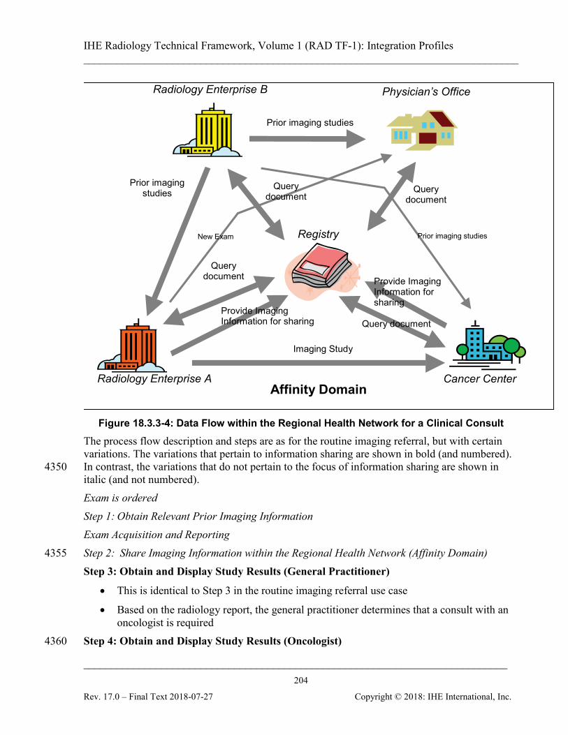
IHE Radiology Technical Framework, Volume 1 (RAD TF-1): Integration Profiles ______________________________________________________________________________
____________________________________________________________________________ 204
Rev. 17.0 – Final Text 2018-07-27 Copyright © 2018: IHE International, Inc.
Radiology Enterprise A
Radiology Enterprise B
Cancer Center
Prior imaging studies
Query document
Affinity Domain
Registry
Query document
Imaging Study
Provide Imaging Information for sharing
New Exam
Query document
Provide Imaging Information for sharing
Physician’s Office
Prior imaging studies
Query document
Prior imaging studies
Figure 18.3.3-4: Data Flow within the Regional Health Network for a Clinical Consult The process flow description and steps are as for the routine imaging referral, but with certain variations. The variations that pertain to information sharing are shown in bold (and numbered). In contrast, the variations that do not pertain to the focus of information sharing are shown in 4350 italic (and not numbered). Exam is ordered Step 1: Obtain Relevant Prior Imaging Information Exam Acquisition and Reporting Step 2: Share Imaging Information within the Regional Health Network (Affinity Domain) 4355 Step 3: Obtain and Display Study Results (General Practitioner)
• This is identical to Step 3 in the routine imaging referral use case
• Based on the radiology report, the general practitioner determines that a consult with an oncologist is required
Step 4: Obtain and Display Study Results (Oncologist) 4360

IHE Radiology Technical Framework, Volume 1 (RAD TF-1): Integration Profiles ______________________________________________________________________________
____________________________________________________________________________ 205
Rev. 17.0 – Final Text 2018-07-27 Copyright © 2018: IHE International, Inc.
• The EHR application in the oncologist’s office, serving as a document consumer, queries the document registry in the regional health network. This query is triggered by a consult request from the general practitioner via paper, fax, phone, and/or electronic notification. The EHR application presents a list of imaging information available for the patient, including the most recent exam completed at Radiology Enterprise A 4365
• The oncologist selects the exam reported by the radiologist as well as a number of relevant prior exams
• The EHR application in the oncologist’s office, serving as an Imaging Document Consumer, retrieves the documents selected from the RIS/PACS document repositories in the regional health network and displays them to the oncologist 4370
• The oncologist reviews the images using image manipulation tools such as window level, zoom, pan, invert, measurement, etc. The oncologist may also apply 3D rendering such as multi-planar reformatting
Oncologist Generates Consult Report
• The oncologist reviews the results of the examination along with prior exams 4375
• The oncologist generates a consult report Step 5: Share Consult Report within the Regional Health Network (Affinity Domain)
• The EHR application in the oncologist’s office, serving as an “Imaging Document Source”, provides the consult report to the document registry for sharing. This has reference to the original imaging exam, which was used during the consult. 4380
Figure 18.3.3-5 shows the transaction diagram for this process flow.
Cancer Centre(Document Consumer)
Rad. Enterprise A(Document Repository) Document RegistryRad. Enterprise A
(Document Consumer)Rad. Enterprise A
(Document Source)Cancer Centre
(Document Source)
Step 1 - Query for relevant priors
Step 1 - Retrieve relevant prior images and reports
Step 2 - ShareImages andFInal Report
Step 2 - Register images and report
Step 3 - Queryfor new exam
Step 3 - Retrieve new exam
Step 5 - Share Consult Report
Step 5 - Register consult report
Step 5 - Querynew exam
(associatedsubmission set)
Rad. Enterprise B(Document Repository)
GP Office(Document Consumer)
Step 4 - Query for new exam andrelevant priors
Step 4 - Retrieve new exam & relevantpriors
Figure 18.3.3-5: Process Flow – Clinical Consult Use Case
IHE Radiology Technical Framework, Volume 1 (RAD TF-1): Integration Profiles ______________________________________________________________________________
____________________________________________________________________________ 206
Rev. 17.0 – Final Text 2018-07-27 Copyright © 2018: IHE International, Inc.
18.3.4 Queries As presented in the use cases, human or machine users may query the Registry in order to 4385 retrieve documents in a subsequent step, based on the query result. The type of query attributes may vary between users or query scenarios, depending on the intent of the query. For instance, human users often wish to query specifically, restricting the search by several query attributes and values. The following query attributes are relevant (but not exhaustive): 4390
• Patient Identity – The patient is expected to be identified by Patient ID
• Exam Identity – The physician is looking for a specific exam. The attributes used to identify the exam may include one or more of the following:
• Date
• Modality 4395
• Body part/anatomical region
• Document type – images, diagnosis, progress report, preliminary report, etc.
• Author – in the case of reports, the physician may well identify the report by its author i.e., the radiologist and / or specialist
The metadata in the query response needs to be sufficient to allow the system consumer to parse 4400 the response and identify relevant priors. Relevant metadata includes (but is not limited to):
• Exam date
• Modality
• Body part/anatomical region
• Procedure code 4405
18.4 Consumer Processing
18.4.1 Consumer Processing – Set of DICOM Instances When the Imaging Document Consumer retrieves a manifest from the Document Repository, it is expected to decode the Key Object Selection Document Instance in order to find the references to DICOM objects. The Imaging Document Consumer is also expected to retrieve the referenced 4410 DICOM objects using DICOM retrieve or WADO. It should not make any assumptions about whether one or more studies are referenced within the Key Object Selection Document.
18.5 Patient Information Reconciliation These considerations can be found in Appendix G.
IHE Radiology Technical Framework, Volume 1 (RAD TF-1): Integration Profiles ______________________________________________________________________________
____________________________________________________________________________ 207
Rev. 17.0 – Final Text 2018-07-27 Copyright © 2018: IHE International, Inc.
18.6 Security considerations 4415
All XDS-I.b actors shall be grouped with either a Secure Node or Secure Application Actor from the ITI ATNA Profile. These actors shall also support the Radiology Audit Trail Option. This grouping is required to provide the capability for security auditing, for establishing a trust relationship between systems exchanging information, and to enable secure data exchange. Some care sites may use alternate mechanisms for providing equivalent security. 4420 Other security considerations can be found in Appendix H.

IHE Radiology Technical Framework, Volume 1 (RAD TF-1): Integration Profiles ______________________________________________________________________________
____________________________________________________________________________ 208
Rev. 17.0 – Final Text 2018-07-27 Copyright © 2018: IHE International, Inc.
19 Mammography Image Integration Profile The Mammography Image Profile specifies how DICOM Mammography images and evidence objects are created, exchanged and used. It describes how Acquisition Modalities transfer Full Field Digital Mammography (FFDM) Images, how CAD systems act as Evidence Creators, and 4425 how Image Displays should retrieve and make use of images and CAD results. It defines the basic display capabilities Image Displays are expected to provide, and which attributes should be used to implement those capabilities. Managing the process of creating, storing and using Mammography Image content is similar to workflow for other image content (e.g., see Scheduled Workflow and Post-Processing Workflow 4430 Profiles). The Mammography Image Profile is designed to provide faithful and complete storage and retrieval of Mammography data and sufficient display functionality to allow adequate review of current and prior images and CAD results for the purpose of primary interpretation by radiologists. It should also be sufficient for secondary review for referring physicians. It does not 4435 address the use of other modalities appropriate for breast imaging such as MR or US.
19.1 Actors/ Transactions Figure 19.1-1 shows the actors directly involved in the Mammography Image Integration Profile and the relevant transactions between them. 4440
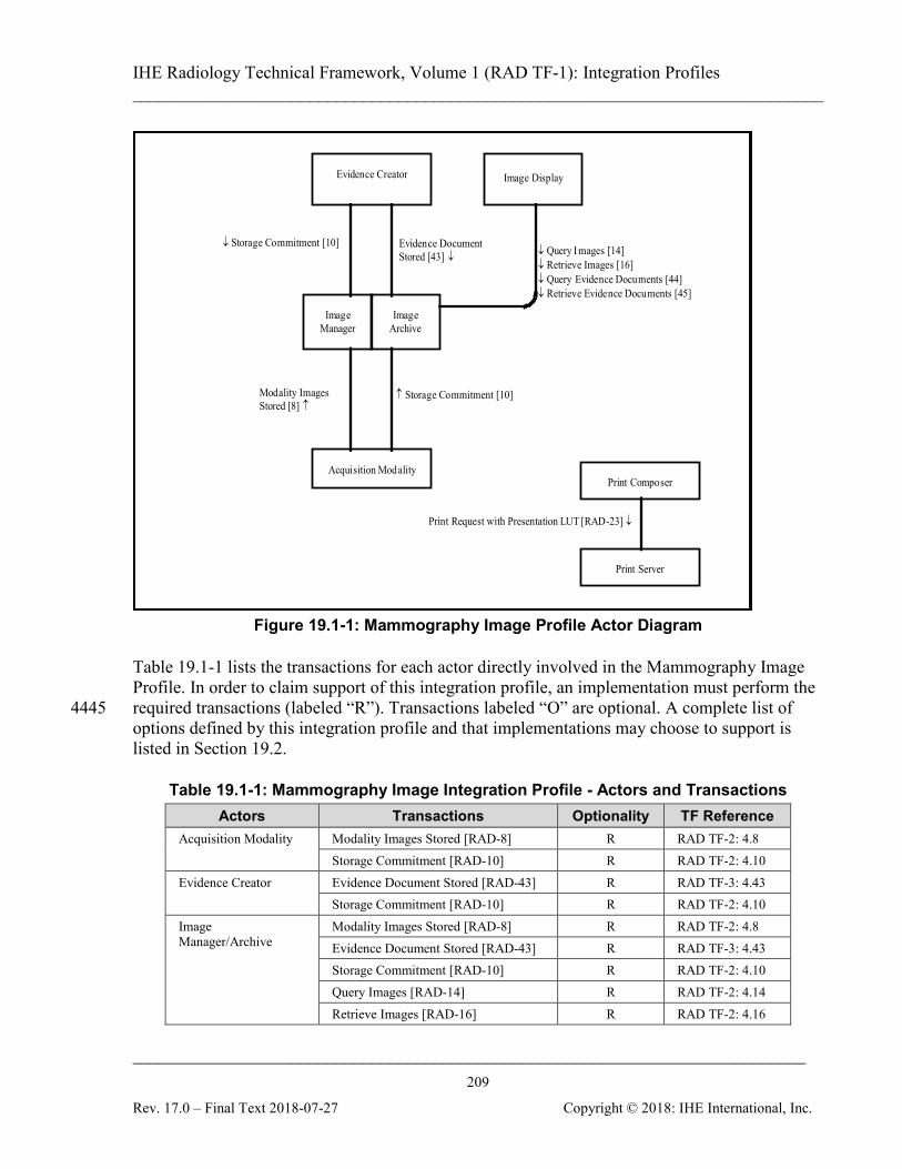
IHE Radiology Technical Framework, Volume 1 (RAD TF-1): Integration Profiles ______________________________________________________________________________
____________________________________________________________________________ 209
Rev. 17.0 – Final Text 2018-07-27 Copyright © 2018: IHE International, Inc.
↓ Query I mages [14] ↓ Retrieve Images [16] ↓ Query Evidence Documents [44] ↓ Retrieve Evidence Documents [45]
Evidence Document Stored [43] ↓
↓ Storage Commitment [10]
Evidence Creator
Acquisition Modality
Image Manager
Image Archive
Image Display
Modality Images Stored [8] ↑
↑ Storage Commitment [10]
Print Request with Presentation LUT [RAD-23] ↓
Print Server
Print Composer
Figure 19.1-1: Mammography Image Profile Actor Diagram
Table 19.1-1 lists the transactions for each actor directly involved in the Mammography Image Profile. In order to claim support of this integration profile, an implementation must perform the required transactions (labeled “R”). Transactions labeled “O” are optional. A complete list of 4445 options defined by this integration profile and that implementations may choose to support is listed in Section 19.2.
Table 19.1-1: Mammography Image Integration Profile - Actors and Transactions Actors Transactions Optionality TF Reference
Acquisition Modality Modality Images Stored [RAD-8] R RAD TF-2: 4.8 Storage Commitment [RAD-10] R RAD TF-2: 4.10
Evidence Creator Evidence Document Stored [RAD-43] R RAD TF-3: 4.43 Storage Commitment [RAD-10] R RAD TF-2: 4.10
Image Manager/Archive
Modality Images Stored [RAD-8] R RAD TF-2: 4.8 Evidence Document Stored [RAD-43] R RAD TF-3: 4.43 Storage Commitment [RAD-10] R RAD TF-2: 4.10 Query Images [RAD-14] R RAD TF-2: 4.14 Retrieve Images [RAD-16] R RAD TF-2: 4.16
IHE Radiology Technical Framework, Volume 1 (RAD TF-1): Integration Profiles ______________________________________________________________________________
____________________________________________________________________________ 210
Rev. 17.0 – Final Text 2018-07-27 Copyright © 2018: IHE International, Inc.
Actors Transactions Optionality TF Reference Query Evidence Documents [RAD-44] R RAD TF-3: 4.44 Retrieve Evidence Documents [RAD-45]
R RAD TF-3: 4.45
Image Display Query Images [RAD-14] R RAD TF-2: 4.14 Retrieve Images [RAD-16] R RAD TF-2: 4.16 Query Evidence Documents [RAD-44] R RAD TF-3: 4.44 Retrieve Evidence Documents [RAD-45]
R RAD TF-3: 4.45
Print Composer Print Request with Presentation LUT [RAD-23]
R RAD TF-2: 4.23
Print Server Print Request with Presentation LUT [RAD-23]
R RAD TF-2: 4.23
19.2 Mammography Image Integration Profile Options 4450
Options that may be selected for this integration profile are listed in the Table 19.2-1 along with the Actors to which they apply. Dependencies between options when applicable are specified in notes.
Table 19.2-1: Evidence Documents - Actors and Options Actor Options TF Reference
Acquisition Modality Partial View RAD TF-2: 4.8.4.1.2.3.1
Image Archive/Manager No options defined --
Image Display Partial View RAD TF-2: 4.16.4.2.2.1.1.7
4455

IHE Radiology Technical Framework, Volume 1 (RAD TF-1): Integration Profiles ______________________________________________________________________________
____________________________________________________________________________ 211
Rev. 17.0 – Final Text 2018-07-27 Copyright © 2018: IHE International, Inc.
19.3 Mammography Image Profile Process Flow
Perform Acquisition
Image Manager/ Image Archive
Acquisition Modality
Modality Images Stored [8] - Mammo Images
Image Display
Query Ima ges [14]
Retrieve Images [16] - Mammo Images
Present Mammo Images to User
Storage Commitment [10]
Query Evidence Document [44]
Retrieve Evidence Document [45] - Mammo CAD
Present Mammo Images with CAD to User
Perform CAD
Evidence Document Stored [43] - Mammo CAD
Storage Commitment [10]
Evidence Creator
(CAD System)
Figure 19.3-1: Basic Process Flow in Mammography Image Profile
The workflow between the Acquisition Modality and the Evidence Creator that is the CAD device is currently outside the scope of IHE to define. 4460

IHE Radiology Technical Framework, Volume 1 (RAD TF-1): Integration Profiles ______________________________________________________________________________
____________________________________________________________________________ 212
Rev. 17.0 – Final Text 2018-07-27 Copyright © 2018: IHE International, Inc.
20 Image Fusion (FUS) This section intentionally, temporarily left blank.
IHE Radiology Technical Framework, Volume 1 (RAD TF-1): Integration Profiles ______________________________________________________________________________
____________________________________________________________________________ 213
Rev. 17.0 – Final Text 2018-07-27 Copyright © 2018: IHE International, Inc.
21 Import Reconciliation Workflow (IRWF) 4465
IMPORTANT NOTE: As of June 2012, IHE introduces an updated Import Reconciliation Profile (IRWF.b) for Trial Implementation. In addition to the original use cases, several new use cases are addressed, and the underlying mechanisms are improved. The IRWF Profile documented in this section has been deprecated by the Radiology Domain and is now replaced by the IRWF.b. . When that supplement becomes Final Text, the contents of this section will 4470 be removed. In the interim, new implementations should be based on IRWF.b, found at http://www.ihe.net/Technical_Frameworks/#radiology. The Import Reconciliation Workflow Integration Profile (IRWF) specifies both the data and workflow requirements for importing existing Evidence Objects and importing Hardcopy from an external Enterprise. Worklists and Patient Demographics Query are provided as mechanisms 4475 to provide local patient and procedure information to be used in the process of reconciling the imported patient/procedure information. Procedure Step Completed messages enable subsequent workflow steps to occur based on the importation of the Evidence Objects. Reconciling critical patient demographics (e.g., Patient Name, Patient ID) and order/procedure Information (e.g., Accession Number) is an important part of the importation process since the 4480 local Enterprise will typically have different identifiers (for patient, orders, etc.) from the Enterprise that created the Evidence Objects or Hardcopy being imported. When the attribute values must be changed, this Profile provides a mechanism to preserve a copy of the original values inside the imported DICOM Composite Objects. This profile also makes it possible to determine whether images, reports and other evidence 4485 objects associated with a particular import have been stored (archived) and are available to subsequent workflow steps, such as post-processing and reporting.
21.1 Actors/Transactions Figure 21.1-1 diagrams the actors involved with this profile and the transactions between them.
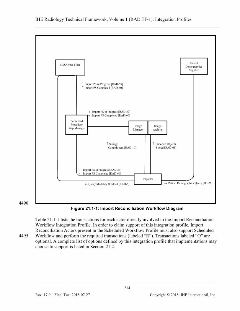
IHE Radiology Technical Framework, Volume 1 (RAD TF-1): Integration Profiles ______________________________________________________________________________
____________________________________________________________________________ 214
Rev. 17.0 – Final Text 2018-07-27 Copyright © 2018: IHE International, Inc.
↑ Imported Objects Stored [RAD-61]
↑ Storage Commitment [RAD-10]
← Query Modality Worklist [RAD-5]
Performed Procedure
Step Manager
↑ Import PS in Progress [RAD-59] ↑ Import PS Completed [RAD-60]
→ Import PS in Progress [RAD-59] → Import PS Completed [RAD-60]
← Import PS in Progress [RAD-59] ← Import PS Completed [RAD-60]
Importer
Image Manager
Image Archive
DSS/Order Filler
→ Patient Demographics Query [ITI-21]
Patient Demographics
Supplier
4490 Figure 21.1-1: Import Reconciliation Workflow Diagram
Table 21.1-1 lists the transactions for each actor directly involved in the Import Reconciliation Workflow Integration Profile. In order to claim support of this integration profile, Import Reconciliation Actors present in the Scheduled Workflow Profile must also support Scheduled Workflow and perform the required transactions (labeled “R”). Transactions labeled “O” are 4495 optional. A complete list of options defined by this integration profile that implementations may choose to support is listed in Section 21.2.
IHE Radiology Technical Framework, Volume 1 (RAD TF-1): Integration Profiles ______________________________________________________________________________
____________________________________________________________________________ 215
Rev. 17.0 – Final Text 2018-07-27 Copyright © 2018: IHE International, Inc.
Table 21.1-1: Import Reconciliation Workflow Integration Profile - Actors and Transactions 4500
Actors Transactions Optionality TF Reference
Department System Scheduler/ Order Filler
Query Modality Worklist [RAD-5] R RAD TF-2: 4.5 Import Procedure Step In Progress [RAD-59] R RAD TF-3:
4.59 Import Procedure Step Completed [RAD-60] R RAD TF-3:
4.60 Patient Demographics Supplier
Patient Demographics Query [ITI-21] R ITI TF-2a: 3.21
Importer Query Modality Worklist [RAD-5] (Note 1) O RAD TF-2:4.5 Patient Demographics Query [ITI-21] (Note 1) O ITI TF-2a: 3.21 Import Procedure Step In Progress [RAD-59] R RAD TF-3:
4.59 Import Procedure Step Completed [RAD-60] R RAD TF-3:
4.60 Imported Objects Stored [RAD-61] R RAD TF-3:
4.61 Storage Commitment [RAD-10] R RAD TF-2:
4.10 Image Manager/ Image Archive
Import Procedure Step In Progress [RAD-59] R RAD TF-3: 4.59
Import Procedure Step Completed [RAD-60] R RAD TF-3: 4.60
Imported Objects Stored [RAD-61] R RAD TF-3: 4.61
Storage Commitment [RAD-10] R RAD TF-2: 4.10
Performed Procedure Step Manager
Import Procedure Step In Progress [RAD-59] R RAD TF-3: 4.59
Import Procedure Step Completed [RAD-60] R RAD TF-3: 4.60
Note 1: The Importer shall support at least one of the Query Modality Worklist or Patient Demographics Query transactions.
Refer to Table 2-1 for other profiles that may be pre-requisites for this profile
21.2 Import Reconciliation Workflow Integration Profile Options Options that may be selected for this integration profile are listed in the Table 21.2-1 along with 4505 the Actors to which they apply. Dependencies between options, when applicable, are specified in notes. 4510
IHE Radiology Technical Framework, Volume 1 (RAD TF-1): Integration Profiles ______________________________________________________________________________
____________________________________________________________________________ 216
Rev. 17.0 – Final Text 2018-07-27 Copyright © 2018: IHE International, Inc.
Table 21.2-1: Import Reconciliation Workflow - Actors and Options Actor Option TF Reference
Department System Scheduler/ Order Filler
No options defined -
Importer Scheduled Import (Note 1) RAD TF-1: 21.2.1 Unscheduled Import (Note 1) RAD TF-1: 21.2.2 Billing and Material Management RAD TF-3: 4.60
Image Manager/ Image Archive No options defined - Performed Procedure Step Manager No options defined -
Note 1: The Importer shall support at least one of the Scheduled Import or Unscheduled Import Options.
The Importer and Image Manager/ Image Archive will likely support a variety of DICOM SOP Classes. It is expected that this level of optionality will be documented in the DICOM 4515 Conformance Statement.
21.2.1 Scheduled Import Option Importers claiming the Scheduled Import Option are required to support the Query Modality Worklist transaction (see RAD TF-2: 4.5) to obtain import worklists and use the patient and procedure information provided to reconcile the imported data. 4520 For further details of this option, refer to RAD TF-3: 4.59.4.1.2.3.1.
21.2.2 Unscheduled Import Option Importers claiming the Unscheduled Import Option are required to support the Patient Demographics Query transaction (See ITI TF-2a: 3.21) to obtain patient demographics for reconciling the imported data. 4525 For further details of this option, refer to RAD TF-3: 4.59.4.1.2.3.2. Note that the identifiers provided by the ITI Patient Demographic Supplier Actor are expected to be consistent with those that would be obtained using SWF transactions. This is necessary to ensure the synchronization of the Patient Demographics from both sources.
21.3 Integration Workflow Process Flow 4530
This section describes the workflow related to importing DICOM data or importing hardcopy created external to the Enterprise. Import Reconciliation Workflow uses many transactions from Scheduled Workflow (See Section 3.3). In most cases there are no changes in these transactions. See Appendix C for an overview of the information exchange between the Department System Scheduler/Order Filler and Image Manager. 4535 Once the desired information has been imported into the local Enterprise it is up to the local institution to determine the retention policies for physical media associated with the import (e.g., films, CDs, DVDs) and the imported data itself.
IHE Radiology Technical Framework, Volume 1 (RAD TF-1): Integration Profiles ______________________________________________________________________________
____________________________________________________________________________ 217
Rev. 17.0 – Final Text 2018-07-27 Copyright © 2018: IHE International, Inc.
21.3.1 Import Process Flow This section describes the typical process flow for managed importation. This profile only 4540 applies to data from patients that have been registered and assumes that the patient demographics information is known and available to the local system and user. If the Patient is not registered, the data is imported and needs to be reconciled by other mechanisms such as PIR.
21.3.1.1 Use Cases The primary use cases for importing radiology information are: 4545
1. External Acquisition or Read: An institution has referred the patient to an external facility for acquisition, or for reading. The institution receives the acquired study on media from the external facility and imports it to the local archive.
2. External Priors: The institution receives media containing prior images and/or reports for a current patient. The data is imported to the local archive and associated with the 4550 patient’s record so they can be referred to as priors during the reading of the current study.
3. Patient Referral: The institution receives media containing a patient’s radiological history associated with a referral or patient transfer. The data is imported to the local archive and associated with the patient’s record. 4555
The importation may be managed in two different ways: 1. Scheduled Import: The institution schedules the import task on an importation worklist
which provides the local demographics and local procedure information. 2. Unscheduled Import: The institution does not electronically schedule the import task and
instead relies on the Importer to obtain local demographics from a Demographics 4560 Supplier.
In either case it is a prerequisite that the patient has been registered so that locally correct demographic information for the patients is available. Importation of “locally unknown” patients followed by Patient Information Reconciliation is not covered by this integration profile. Importation could be performed piecewise on a physician’s workstation, or batched at a central 4565 location. The data may arrive at the institution by a variety of transport mechanisms including hardcopy (films, prints), media (CDs, DVDs) or simple network transfer. This profile does not dictate a particular transport mechanism. For any import, there may exist information in addition to the media, which will be taken into 4570 account by the importing enterprise but its usage is not specified by IHE. This information may be available electronically, written or orally. Main examples for such information are:
• Administrative information like checklists, importation rules, workflow codes or billing items.
IHE Radiology Technical Framework, Volume 1 (RAD TF-1): Integration Profiles ______________________________________________________________________________
____________________________________________________________________________ 218
Rev. 17.0 – Final Text 2018-07-27 Copyright © 2018: IHE International, Inc.
• Clinical information like lab reports, discharge summaries, ECGs, potentially as PDI web 4575 data.
Note that the person importing the Evidence Objects or Hardcopy can be assumed to have the most comprehensive and complete information available for the importing task. In case of exceptions, the import may need to be aborted (see RAD TF-3: 4.60.4.1.2.2 for Exception Management). 4580 After the importation is done and the imported evidence objects are available through the Image Manager/ Image Archive (which may be indicated by an Instance Availability Notification), the enterprise may schedule subsequent steps like reading or reporting.
21.3.1.2 Scheduled Import Process Flow An enterprise internally schedules an import, e.g., associated with an external acquisition or read. 4585 There may be other scheduling items, which are not within the scope of the Technical Framework, but will be taken into account by the Enterprise:
• For external referrals, patient and order information needs to be conveyed to the external Enterprise.
• Clinical information may be received in addition to the DICOM information, e.g., 4590 electronic referrals, Lab Reports, Clinical Summaries, or PDI web information.
• The importation of data is typically a scheduled event separate from how the data is used (images to be reported, historical data to be used in-conjunction with a current procedure, etc.).
• The importation scheduling information may include instructions, e.g., which studies, 4595 series or images are to be imported.
The following steps can be identified in the scheduled process flow:
• Using Scheduled Workflow, the relevant study data to be imported is available in the scheduled procedure step. Note that the Patient Registration and Procedure Ordering all use the Scheduled Workflow Profile (See Sections 3.3.1, 3.3.2, 3.3.3). 4600
• Depending on the type of media to be imported, the procedure step can be scheduled to the appropriate Importing device (e.g., Film Scanner, PDI Workstation).
• The SCHEDULED IMPORT Option is used to import the evidence objects and reconcile the patient and procedure data (e.g., to change the recorded Patient ID to the local Patient ID) using the Modality Worklist Query. The resultant DICOM objects are stored in the 4605 PACS.
• Errors and exceptions during import are handled by using Exception Management described in RAD TF-3: 4.60.4.1.2.2.
• Subsequent steps may be
• performed, such as implicit post-processing (see Section 3.3.5); 4610
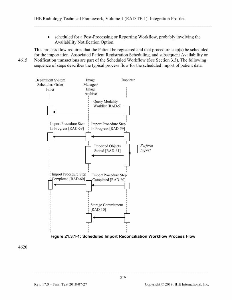
IHE Radiology Technical Framework, Volume 1 (RAD TF-1): Integration Profiles ______________________________________________________________________________
____________________________________________________________________________ 219
Rev. 17.0 – Final Text 2018-07-27 Copyright © 2018: IHE International, Inc.
• scheduled for a Post-Processing or Reporting Workflow, probably involving the Availability Notification Option.
This process flow requires that the Patient be registered and that procedure step(s) be scheduled for the importation. Associated Patient Registration Scheduling, and subsequent Availability or Notification transactions are part of the Scheduled Workflow (See Section 3.3). The following 4615 sequence of steps describes the typical process flow for the scheduled import of patient data. Image
Manager/ Image
Archive
Importer Department System Scheduler/ Order
Filler
Perform Import
Imported Objects Stored [RAD-61]
Storage Commitment [RAD-10]
Import Procedure Step In Progress [RAD-59]
Import Procedure Step In Progress [RAD-59]
Query Modality Worklist [RAD-5]
Import Procedure Step Completed [RAD-60]
Import Procedure Step Completed [RAD-60]
Figure 21.3.1-1: Scheduled Import Reconciliation Workflow Process Flow
4620
IHE Radiology Technical Framework, Volume 1 (RAD TF-1): Integration Profiles ______________________________________________________________________________
____________________________________________________________________________ 220
Rev. 17.0 – Final Text 2018-07-27 Copyright © 2018: IHE International, Inc.
21.3.1.2.1 Scheduled Import Data Reconciliation Importation requires that some of the Patient/Procedure information be treated differently than prescribed in Scheduled Workflow. The Study UID provided by the Modality Worklist shall be ignored and the reconciliation rules shall be followed. As part of the import process, the Importer reconciles the patient data as 4625 needed (e.g., to change the recorded Patient ID to the local Patient ID). See RAD TF-2: Appendix A.5 for a full list of the reconciliation requirements. The original DICOM object identifiers must be maintained in the imported DICOM Composite Objects. The policies of the importing enterprise will determine
• if demographics from the Import Data can be used (e.g., Birth Date, Patient Sex) 4630
• whether or how enterprise-specific codes in the imported data are coerced or ignored
21.3.1.3 Unscheduled Import Process Flow An enterprise has received evidence objects for import that are not part of an order or scheduled procedure in one of its information systems, e.g., relevant priors prior to a consultation. There is no scheduled procedure to trigger the importation. The actual task of importation may be a 4635 batched process that does not schedule individual importations.
• Aside from the physical media (e.g., films, CDs), there may be clinical information in addition to the DICOM data in electronic, written or oral format, such as referral letters The incorporation of this information into the Enterprise is out of scope for the Import Reconciliation Workflow. 4640
The following steps can be identified in this process flow:
• The User does the import at an appropriate device (e.g., a film scanner is used to digitize films, a workstation with PDI capabilities is used to import PDI media).
• The UNSCHEDULED IMPORT Option is used to retrieve the Patient Demographics information, import the Evidence Objects and to reconcile the patient data (e.g., to 4645 change the recorded Patient ID to the local Patient ID) using the Patient Demographics Query. The resultant DICOM objects are stored in the PACS.
• Errors and exceptions during import are handled by using Exception Management described in RAD TF-3: 4.60.1.2.2.
• The Evidence Objects are available from the PACS and may be used in subsequent 4650 scheduled or unscheduled steps, or at a later time.
This process flow requires that the Patient be registered. Associated Patient Registration, and subsequent Availability or Notification transactions are part of the Scheduled Workflow (See Section 3.3). The following sequence of steps describes the typical process flow for the unscheduled import of patient data. 4655

IHE Radiology Technical Framework, Volume 1 (RAD TF-1): Integration Profiles ______________________________________________________________________________
____________________________________________________________________________ 221
Rev. 17.0 – Final Text 2018-07-27 Copyright © 2018: IHE International, Inc.
Image Manager/
Image Archive
Importer
Department System Scheduler/ Order
Filler
Perform Import
Imported Objects Stored [RAD-61]
Storage Commitment [RAD-10]
Import Procedure Step In Progress [RAD-59]
Import Procedure Step In Progress [RAD-59]
Import Procedure Step Completed [RAD-60]
Import Procedure Step Completed [RAD-60]
Demographic Supplier
Patient Demographic Query [ITI-21]
Figure 21.3.1-2: Unscheduled Import Reconciliation Workflow Process Flow

IHE Radiology Technical Framework, Volume 1 (RAD TF-1): Integration Profiles ______________________________________________________________________________
____________________________________________________________________________ 222
Rev. 17.0 – Final Text 2018-07-27 Copyright © 2018: IHE International, Inc.
21.3.1.3.1 Unscheduled Import Data Reconciliation 4660 As part of the import process, the Importer reconciles the patient data as needed (e.g., to change the recorded Patient ID to the local Patient ID). The original DICOM object identifiers must be maintained in the imported DICOM Composite Objects in order to maintain the relationship of the Images within the Study (See RAD TF-2: Appendix A.5). The policies of the importing enterprise will determine 4665
• whether demographics from the Import Data can be used (e.g., Birth Dates, Patient Sex)
• whether or how enterprise-specific codes in the imported data are coerced or ignored
21.3.2 Import Exception Management Workflow Exception management Workflow is required for Import Reconciliation Workflow. This case addresses the need to manage errors generated through the Import Reconciliation Workflow such 4670 as:
• Selection of the incorrect Scheduled Procedure Step from the Modality Worklist
• Selection of the incorrect Patient Demographics from the Patient Demographics List
• The inability to support the DICOM Composite Objects to be imported
• Equipment Failure 4675
• Bad media Some of these exception cases are addressed using required functionality for IHE actors in the Import Reconciliation Workflow and Scheduled Workflow Profiles, while others make use of the IMPORT PPS EXCEPTION MANAGEMENT (See RAD TF-3: 4.60.4.1.2.2). The following numbered items list exception cases that shall be supported by the actors listed in each item. 4680
IHE Radiology Technical Framework, Volume 1 (RAD TF-1): Integration Profiles ______________________________________________________________________________
____________________________________________________________________________ 223
Rev. 17.0 – Final Text 2018-07-27 Copyright © 2018: IHE International, Inc.
22 Radiation Exposure Monitoring (REM) Integration Profile This integration profile specifies how details of radiation exposure resulting from imaging procedures are exchanged among the imaging systems, local dose information management systems and cross-institutional systems such as dose registries. The data flow in the profile is intended to facilitate recording individual procedure dose information, collecting dose data 4685 related to specific patients, and performing population analysis. Use of the relevant DICOM objects (CT Dose SR, Projection X-Ray Dose SR) is clarified and constrained. The Profile focuses on conveying the details of individual irradiation events. A proper radiation exposure management program at an imaging facility would involve a medical physicist and 4690 define such things as local policies, local reporting requirements, annual reviews, etc. Although this Profile is intended to facilitate such activities, it does not define such policies, reports or processing, or in itself constitute a radiation exposure management program. The Profile addresses dose reporting for imaging procedures performed on CT and projection X-ray systems, including mammography. It does not currently address procedures such as nuclear 4695 medicine (PET or SPECT), radiotherapy, or implanted seeds. The Profile is intended to support quality assurance (QA) of the technical process (was the dose appropriate for the procedure performed). It is less suited to QA of the ordering process (was the procedure ordered/scheduled appropriate for the indications (appropriateness criteria)), or QA of the operational process (were any differences between the procedure scheduled and the 4700 procedure performed justified by the situation/equipment/patient and appropriately approved).
Background In the vast majority of medical procedures involving radiation, the potential benefit to the patients’ health far outweighs the potential risk, but the trade-off should not be overlooked, and technological mechanisms can facilitate a conscious evaluation of that trade-off. 4705 Estimating radiation dose delivered to patients for medical purposes can facilitate a number of important activities:
• For facilities exposing patients to radiation, monitoring such exposures can help ensure their policies, procedures and protocols are adequate and being followed appropriately.
• For imaging physicians, monitoring such exposures can assist them in determining how 4710 changes in techniques and protocols impact radiation dose as well as image quality. This will enable them to maintain patient doses As Low As Reasonably Achievable (ALARA).
• For patients’ physicians, overall data provided from monitoring such exposures can help them determine (in consultation with the imaging physician) if the benefit from the 4715 diagnostic information provided by an individual examination (or additional examinations) outweigh any small risk that may be associated with the imaging exam.
IHE Radiology Technical Framework, Volume 1 (RAD TF-1): Integration Profiles ______________________________________________________________________________
____________________________________________________________________________ 224
Rev. 17.0 – Final Text 2018-07-27 Copyright © 2018: IHE International, Inc.
• For medical physicists, having such post-procedure information available for individual patients may help them make essential patient-specific dose estimates for pregnant patients or patients exhibiting skin erythema as a result of long fluoroscopy examinations. 4720
• For professional societies and regulatory agencies, a collection of exposure data can be useful when setting or reviewing radiation dose related guidelines and regulations. Many such groups have expressed a desire to establish standards of practice or dose reference levels based on a quantitative understanding of current practice, however they have found it prohibitively difficult to collect such data. 4725
• For physicists and physicians, this kind of data can be vital to answering some of the fundamental scientific questions that remain and developing a more detailed understanding of the health impacts of radiation exposure and how it should be measured and managed.
However, it is important to understand the technical and practical limitations of such dose 4730 monitoring and the reasons why the monitored values may not accurately provide the radiation dose administered to the patient:
• The values provided by this tool are not “measurements” but only calculated estimates.
• For computed tomography, “CTDI” is a dose estimate to a standard plastic phantom. Plastic is not human tissue. Therefore, CTDI should not be represented as the dose 4735 received by the patient.
• For planar or projection imaging, the recorded values may be exposure, skin dose or some other value that may not be patient’s body or organ dose.
• It is inappropriate and inaccurate to add up dose estimates received by different parts of the body into a single cumulative value. 4740
Despite such limitations, interest in monitoring radiation dose estimates is clearly expressed in such documents as the European directive Euratom 97/43 and the American College of Radiology Dose Whitepaper [1]. DICOM, with advice from the IEC, AAPM, ACR, NCRP and others, developed DICOM Dose objects appropriate for radiation dose monitoring By profiling automated methods of distribution, dose information can be collected and evaluated 4745 without imposing a significant administrative burden on staff otherwise occupied with caring for patients.
22.1 Actors/ Transactions Figure 22.1-1 shows the actors directly involved in the Radiation Exposure Monitoring Integration Profile and the relevant transactions between them. Other actors that may be 4750 indirectly involved due to their participation in other relevant transactions are not necessarily shown.
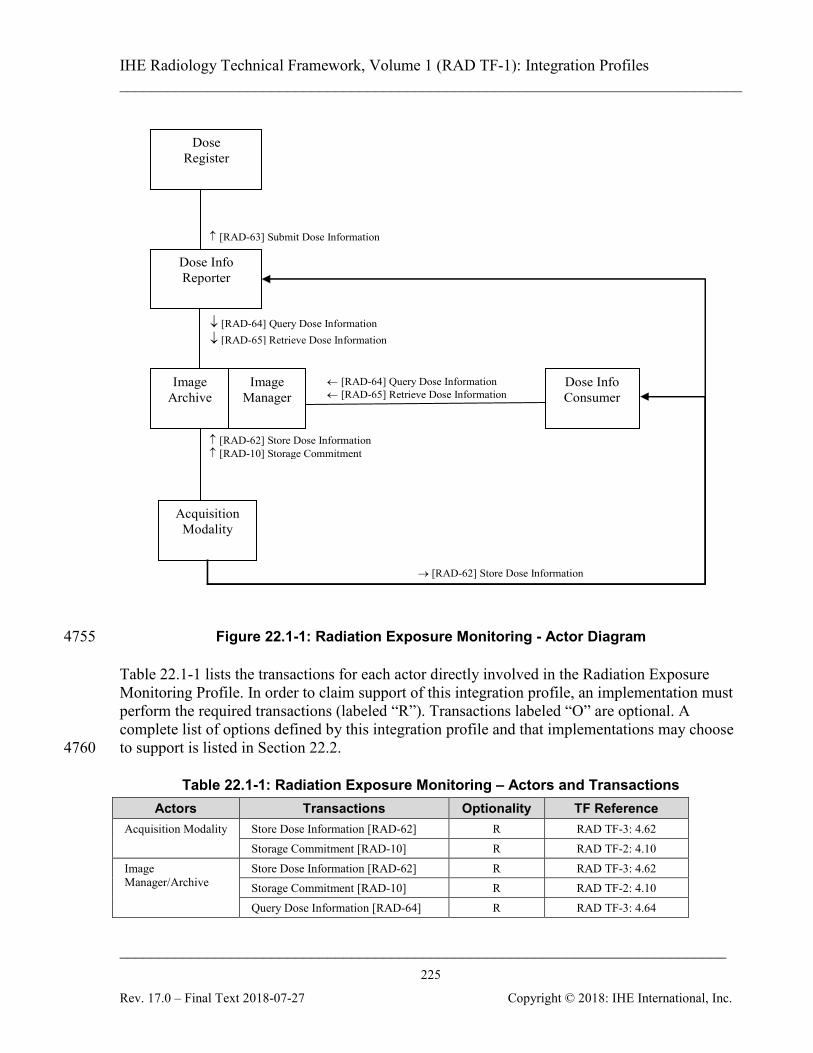
IHE Radiology Technical Framework, Volume 1 (RAD TF-1): Integration Profiles ______________________________________________________________________________
____________________________________________________________________________ 225
Rev. 17.0 – Final Text 2018-07-27 Copyright © 2018: IHE International, Inc.
→ [RAD-62] Store Dose Information
↑ [RAD-63] Submit Dose Information
← [RAD-64] Query Dose Information ← [RAD-65] Retrieve Dose Information
↓ [RAD-64] Query Dose Information ↓ [RAD-65] Retrieve Dose Information
Dose Register
Dose Info Consumer
↑ [RAD-62] Store Dose Information ↑ [RAD-10] Storage Commitment
Dose Info Reporter
Acquisition Modality
Image Archive
Image Manager
Figure 22.1-1: Radiation Exposure Monitoring - Actor Diagram 4755
Table 22.1-1 lists the transactions for each actor directly involved in the Radiation Exposure Monitoring Profile. In order to claim support of this integration profile, an implementation must perform the required transactions (labeled “R”). Transactions labeled “O” are optional. A complete list of options defined by this integration profile and that implementations may choose to support is listed in Section 22.2. 4760
Table 22.1-1: Radiation Exposure Monitoring – Actors and Transactions Actors Transactions Optionality TF Reference
Acquisition Modality Store Dose Information [RAD-62] R RAD TF-3: 4.62 Storage Commitment [RAD-10] R RAD TF-2: 4.10
Image Manager/Archive
Store Dose Information [RAD-62] R RAD TF-3: 4.62 Storage Commitment [RAD-10] R RAD TF-2: 4.10 Query Dose Information [RAD-64] R RAD TF-3: 4.64
IHE Radiology Technical Framework, Volume 1 (RAD TF-1): Integration Profiles ______________________________________________________________________________
____________________________________________________________________________ 226
Rev. 17.0 – Final Text 2018-07-27 Copyright © 2018: IHE International, Inc.
Actors Transactions Optionality TF Reference Retrieve Dose Information [RAD-65] R RAD TF-3: 4.65
Dose Information Reporter
Query Dose Information [RAD-64] R RAD TF-3: 4.64 Retrieve Dose Information [RAD-65] R RAD TF-3: 4.65 Submit Dose Information [RAD-63] R RAD TF-3: 4.63 Store Dose Information [RAD-62] R RAD TF-3: 4.62
Dose Information Consumer
Query Dose Information [RAD-64] R RAD TF-3: 4.64 Retrieve Dose Information [RAD-65] R RAD TF-3: 4.65 Store Dose Information [RAD-62] R RAD TF-3: 4.62
Dose Registry Submit Dose Information [RAD-63 R RAD TF-3: 4.63
An Acquisition Modality in this profile might not necessarily generate the irradiation itself. An Acquisition Modality may generate Dose objects on behalf of an irradiating modality system based on irradiation details obtained by manual input and/or some proprietary method, as long as 4765 it can do so completely and correctly. Actors are encouraged to describe in their DICOM Conformance Statement additional details of how they implement specific DICOM-based transactions (e.g., the time frame in which an Acquisition Modality is able to store a Dose object relative to the completion of the irradiation event). 4770
22.2 Radiation Exposure Monitoring Integration Profile Options Options that may be selected for this integration profile are listed in the Table 22.2-1 along with the Actors to which they apply. Dependencies between options when applicable are specified in notes. Currently there are no options defined in this profile. 4775
Table 22.2-1: Radiation Exposure Monitoring – Actors and Options Actor Options TF Reference
Acquisition Modality No options defined - -
Image Manager/Archive No options defined - -
Dose Information Reporter No options defined - - Dose Information Consumer No options defined - -
Dose Registry No options defined - -
22.3 Radiation Exposure Monitoring Process Flow This Profile addresses the flow of dose information from the source, through the organization and beyond. It does not mandate, but is intended to facilitate the ability to do things like: 4780

IHE Radiology Technical Framework, Volume 1 (RAD TF-1): Integration Profiles ______________________________________________________________________________
____________________________________________________________________________ 227
Rev. 17.0 – Final Text 2018-07-27 Copyright © 2018: IHE International, Inc.
• view the estimated dose a patient (or particular organs) received for a certain exam
• determine if the estimated dose for a given procedure, system or physician regularly exceeds some reference level, policy trigger or is otherwise an "outlier" requiring further investigation
• compute the population "dose summary" for a specific exam in a certain hospital or 4785 region
• compute the population "dose summary" for a certain pathology or indication
• compare exam-specific "dose summaries" against other sites/regions, against local policy targets or against standards of practice
Note: To summarize dose for a specific exam type or pathology, the Dose Information Reporter needs to know such 4790 details for each dose object. IHE has required that such information be provided in the dose objects as coded values so they will be machine readable. If consistent codes are present in the dose objects, they can simply be sorted or mapped by a lookup table (See RAD TF-1 Appendix I.1.1 Code Set Management). Alternatively a Dose Information Reporter might be grouped with a DSS/Order Filler so such details could be obtained for each Accession #. In either case, a critical task for sites wishing to do such analysis is to choose a set of codes for 4795 exam types and pathologies and to distribute and use them consistently across their systems.
22.3.1 General Case Typically, irradiation events occur on X-ray based imaging modalities, which record them in Dose objects that are part of the same study as the images and stored to the Image Manager/Archive. 4800 In many organizations, a Dose Information Reporter will collect Dose objects covering a particular period (e.g., today, this week or last month), analyze them, compare to site policy and generate summary reports. All, or a sampled subset of the Dose objects might be submitted to a National Registry to facilitate composing population statistics and other research. Such Dose objects will generally 4805 undergo a configurable de-identification process prior to submission.
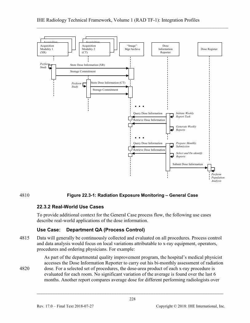
IHE Radiology Technical Framework, Volume 1 (RAD TF-1): Integration Profiles ______________________________________________________________________________
____________________________________________________________________________ 228
Rev. 17.0 – Final Text 2018-07-27 Copyright © 2018: IHE International, Inc.
Perform Population Analysis
Store Dose Information (CT)
Acquisition Modality 2 (CT)
Acquisition Modality 2 (CT)
Acquisition Modality 1 (XR)
Acquisition Modality 1 (XR)
Acquisition Modality 1 (XR)
“Image” Mgr/Archive
Dose Information
Reporter
Dose Register
Acquisition Modality 2 (CT)
Perform Study Storage Commitment
Store Dose Information (XR)
Storage Commitment
Perform Study
Retrieve Dose Information
Query Dose Information
Submit Dose Information
Prepare Monthly Submission
Retrieve Dose Information
Query Dose Information
Generate Weekly Reports
. . .
. . .
Initiate Weekly Report Task
Select and De-identify Reports
Figure 22.3-1: Radiation Exposure Monitoring – General Case 4810
22.3.2 Real-World Use Cases To provide additional context for the General Case process flow, the following use cases describe real-world applications of the dose information.
Use Case: Department QA (Process Control) Data will generally be continuously collected and evaluated on all procedures. Process control 4815 and data analysis would focus on local variations attributable to x-ray equipment, operators, procedures and ordering physicians. For example:
As part of the departmental quality improvement program, the hospital’s medical physicist accesses the Dose Information Reporter to carry out his bi-monthly assessment of radiation dose. For a selected set of procedures, the dose-area product of each x-ray procedure is 4820 evaluated for each room. No significant variation of the average is found over the last 6 months. Another report compares average dose for different performing radiologists over
IHE Radiology Technical Framework, Volume 1 (RAD TF-1): Integration Profiles ______________________________________________________________________________
____________________________________________________________________________ 229
Rev. 17.0 – Final Text 2018-07-27 Copyright © 2018: IHE International, Inc.
several interventional procedures, and a third report compares performing technologists for CT and radiographic exams. It becomes clear that for a certain interventional procedure a newly arrived radiologist tends 4825 to generate 2 to 3 times the dose-area product of his colleagues, whose averages are in a narrow cluster well below the newcomer. While the dose-area product sub-total in fluoroscopy is similar among the radiologists (and is consistent with the average fluoroscopy time of the report), there is a significant discrepancy in dose-area product for the acquisition sub-total. The number of acquired images (higher than the departmental average) also 4830 corroborates this. The medical physicist writes a memo to the department chair, who raises the issue at the weekly radiologist meeting. Upon discussion, it becomes clear the radiologist uses a supplementary acquisition which his colleagues do not. After more discussion, the radiologists agree that the acquisition, although moderately useful, probably does not bring 4835 any information that would not be picked up in the rest of the exam, and it is agreed it should not be done. The medical physicist reviews the situation a month later, and is reassured that the results show all radiologists now have similar dose-area product for that procedure.
Hospitals generally have policies relating to patient radiation dose, often benchmarking performance estimates against published reference levels. Policies (and reference levels) are 4840 often broken down by procedure, patient age group, and perhaps weight group, or gender. Analysis tools can help sites monitor whether policies are being followed, and measure progress toward improvement targets. While image quality generally sets the low side limit on dose (too low and the images are unacceptable to the radiologists), QA programs can be an effective way to counter dose creep, establish upper trigger levels and encourage lower values. 4845
Use Case: Patient Impact Evaluation A few days after a CT exam is carried out for a young female patient, the referring physician identifies the patient as pregnant (which was not known at the time of the scan). The referring physician requests an evaluation of the risk to the fetus from the radiologist who read the exam. The radiologist requests a hospital medical physicist to provide an estimate of the radiation dose 4850 received by the uterus in the course of the CT exam. The medical physicist retrieves the images and dose data for the study in question, and determines with the help of the radiologist which series encompass the uterus. Knowing which series are of interest, the medical physicist is then able to leverage the dose indicators and weight of the patient contained in the dose and image objects to estimate the total dose to the uterus. 4855 How the information is recorded and distributed will vary, but in this particular hospital, the dose estimate is then provided to the clinical coordinator of the department, who enters it in the RIS, appending a statement to the report (which had already been signed off), and demoting the status of the study to "pending signature". Before signing off the report, the radiologist completes the addendum with her estimate of the risk to the fetus given the dose measurement, and 4860 communicates this result by phone to the referring physician, who also receives the written addendum electronically signed by the radiologist a few days later.
IHE Radiology Technical Framework, Volume 1 (RAD TF-1): Integration Profiles ______________________________________________________________________________
____________________________________________________________________________ 230
Rev. 17.0 – Final Text 2018-07-27 Copyright © 2018: IHE International, Inc.
Important analysis details include time/date of scans, body area irradiated, exposure values.
Use Case: Population Dose and Dose Indicators Organizations wishing to assess Population Dose and Dose Indicators will often set up a Dose 4865 Registry. A sampling of dose estimates with reasonable accuracy are collected from a number of clinical sites, often for specific targeted procedures. It is not necessary that every procedure performed be collected; a representative sample of procedures is sufficient. That being said, it may be easier for a dose registry to discard a portion of the procedures submitted than to try and get each submitting site to follow the same regimen for selecting procedures to submit. 4870 Note that conversion of estimated dose values to patient or population risk involves complex scientific questions. Streamlining the collection of additional, more detailed data can only help. For further discussion, see RAD TF-1: Appendix I – Deployment of Dose Registries.
Use Case: Dose Reference Levels Quantitative Dose Guidelines are often distributed in the form of Dose Reference Levels for 4875 typical procedures for groups of patients of different characteristics (e.g., a target dose level to stay below for adult head studies). Such guidelines are often the logical result of analyzing Population Dose or other data mining performed by a professional society or regulatory body.
Use Case: Site Benchmarking 4880 Imaging facilities may find it useful to compare their dose profile by modality, exam type, and pathology to other facilities of the same type, facilities in the same region, and to the nation as a whole. A national radiation dose registry might provide facilities submitting data with reports comparing them to regional and national benchmarks.
Use Case: Population Epidemiology 4885 To analyze certain population epidemiology questions, e.g., the occupational hazards of being a radiologist, one has patients with a known disease and would like to use the patients’ radiation history to estimate the likelihood of radiogenic etiology. Requirements include access to a complete radiation history of each such patient. Because of long latent periods, data must be archived in a manner that makes it both physically readable and dosimetrically intelligible years, 4890 or decades, after it is written.
Use Case: Clinical Trials The radiation dose can be an important component of a clinical trial. For example, a trial of a proposed low-dose CT lung screening procedure would benefit from being able to collect dose data to balance against the resulting detection rates for a proper trade-off analysis. Co-4895 submission of image and Dose objects could facilitate this.
IHE Radiology Technical Framework, Volume 1 (RAD TF-1): Integration Profiles ______________________________________________________________________________
____________________________________________________________________________ 231
Rev. 17.0 – Final Text 2018-07-27 Copyright © 2018: IHE International, Inc.
Use Case: Procedure Operational Awareness (Quasi-realtime) Some regulations already require that Ka,r be displayed on fluoroscopy systems within sight of the primary operator. This permits the operator to factor radiation effects into the continuous clinical benefit-risk analysis occurring during any procedure (keeping in mind that Ka,r is not the 4900 same as cumulative skin dose). Such direct display can be handled by the modality and has no need of the transactions provided by this profile
Use Case: Clinical Management Dose estimates and dose estimate maps can facilitate planning for subsequent procedures (such as deciding how much time to allow for tissue to heal, or deciding what direction to image from 4905 to avoid damaged tissues). Particularly for interventional fluoroscopy, the dose distribution delivered by each procedure should be part of the patients’ medical record.
Use Case: Longitudinal Patient Dose Record The lifetime radiation dose received by a patient can be stored and retrieved from a longitudinal record, whether it is stored as part of the entire patient history, or as a separate entity. This may 4910 in future form a vital source of information for clinical decision-making with respect to the appropriateness and risk of an additional procedure, as well as remediation in the event of an unfortunate outcome. As methods evolve for estimating effective dose to radio-sensitive tissues and quantifying cancer risk, these can be retrospectively applied to stored dose information. This use case is distinct from registry use cases, since the goal is to track the individual, rather than 4915 population, dose. It is distinct from the Clinical Management use case, since it spans a longer term, multiple episodes of care and multiple sites. This use case necessarily requires support of acquisition and collation of dose information from multiple acquisition sites, since a patient may be provided healthcare at many sites over their entire life time. 4920
22.3.3 Example REM Profile Deployments These examples are intended to illustrate a few ways the Radiation Exposure Monitoring Profile might be deployed inside a hospital or clinic. It is not intended to be normative, or to show all possible deployments. Further practical examples related to the use of a Registry appear in Appendix I. 4925
22.3.3.1 A Hospital Scenario The Radiology PACS would perhaps implement the Image Manager/Archive in this profile and also the PIR, SWF Profiles. The RIS might implement the Dose Information Reporter in this profile and be grouped with a DSS/Order Filler supporting the SWF and PIR Profiles. 4930 A Dose Mapping Workstation might implement both the Dose Information Consumer (to obtain Dose objects) and the Evidence Creator (to submit new ones).

IHE Radiology Technical Framework, Volume 1 (RAD TF-1): Integration Profiles ______________________________________________________________________________
____________________________________________________________________________ 232
Rev. 17.0 – Final Text 2018-07-27 Copyright © 2018: IHE International, Inc.
Perhaps Cardiology has a separate PACS which also implements an Image Manager/Archive for the cardiology modalities. The Dose Information Reporter (in the Radiology RIS) could query both Archives and manage dose for the hospital in one place. 4935
22.3.3.2 An Imaging Clinic Scenario Many imaging clinics will have a PACS and could follow a similar layout to the Hospital above. Alternatively, a PACS-less clinic which decides they do not need long term archiving or reconciliation of the Dose objects might not have an Image Manager/Archive. The Office Management System or a standalone workstation could implement the Dose 4940 Information Reporter, and takes advantage of its ability to receive Dose objects directly from the local modalities.
22.3.3.3 A Longitudinal Patient Record Scenario Multiple sites, including hospitals and imaging clinics, implement Acquisition Modalities and/or Image Manager/Archives that provide information in response to queries from a local Dose 4945 Information Reporter. The local Dose Information Reporter transmits identifiable (as opposed to de-identified) dose information to a remote Dose Register nominated by the patient to act as their lifetime repository of longitudinal dose information. Each local site may use different forms of the patient’s name and different domains for patient identifier, and accordingly the Dose Information Reporter 4950 should include multiple identifiers for different domains, and/or regional or national identifiers, if known, and the Dose Register may need to be grouped with a PIX Manager or similar mechanism to resolve identities. See also the issues raised in the Multiple Image Manager/Archive (MIMA) Trial Implementation supplement. If the remote Dose Register is grouped with its own Dose Information Reporter Actor, then given 4955 the appropriate authorization by the patient, another local site with a Dose Consumer Actor may access the information to make clinical decisions. Additionally, if remote Dose Register and/or Dose Information Reporter is also capable of modeling effective dose using organ segmentation information, it may want to receive and store the images reconstructed from the irradiation events described in the dose objects, and hence to 4960 be grouped with a remote Image Manager/Archive Actor.
22.4 Radiation Exposure Monitoring Profile Security Considerations Dose Objects have the same security considerations as images. Security and Privacy policies may require the de-identification of some or all of the PHI details prior to the submission or use of Dose Objects (see RAD TF-3: 4.63.4.1.2.1). De-identification 4965 behavior may need to vary by destination due to differences in PHI exposure risk and the need to retain some details, such as approximate patient age or weight, when performing Radiation Dose analysis.

IHE Radiology Technical Framework, Volume 1 (RAD TF-1): Integration Profiles ______________________________________________________________________________
____________________________________________________________________________ 233
Rev. 17.0 – Final Text 2018-07-27 Copyright © 2018: IHE International, Inc.
22.5 Relation to Other Profiles Several synergies and interactions of the Radiation Exposure Monitoring Profile with other 4970 profiles are specifically called out here.
22.5.1 Radiology Profiles
22.5.1.1 Portable Data for Imaging (PDI) The Dose objects from this profile may be included on PDI media, either along with the rest of the study data to provide a “complete package”, or on their own as a way of conveying Dose 4975 objects to a patient, another organization or a dose registry.
22.5.1.2 Patient Identification Reconciliation (PIR) An Image Manager/Archive which also implements the Patient Identification Reconciliation Profile is expected to reconcile the Dose objects along with the rest of the DICOM objects in a patients’ study. This is highly desirable. 4980
22.5.1.3 Teaching Files and Clinical Trials Export (TCE) As DICOM objects, the Dose objects can be referenced in a TCE manifest and processed along with other objects from a study. This could allow submitting dose details in clinical trials where such information is relevant, or including dose details in a teaching file, perhaps one specifically addressing protocol dose and the effects on image quality. 4985
22.5.2 ITI Profiles
22.5.2.1 Patient Identity Cross-referencing (PIX) The PIX Profile could clearly be useful if there is a need to collate patient dose records across multiple Patient ID Domains. It could also be useful if a single Dose Information Reporter is querying multiple Image Manager/Archives in different Patient ID Domains. 4990
22.5.2.2 Cross-Enterprise Document Sharing (XD*) Since Dose objects are normal DICOM SR objects, the collection of XDS Profiles (XDS, XDS-I, XDR, XDM, etc.) can be used to distribute or access dose records across multiple sites.
22.5.2.3 Consistent Time (CT) Consistent Time is particularly useful if a gantry and reader are trying to compose a Dose object 4995 by synchronizing study details based on timestamps.
22.5.2.4 Audit Trail and Node Authentication (ATNA) Audit events relevant to the transactions of the REM Profile are identified in RAD TF-3: Table 5.1-2 in the Radiology Audit Trail Option.
5000
IHE Radiology Technical Framework, Volume 1 (RAD TF-1): Integration Profiles ______________________________________________________________________________
____________________________________________________________________________ 234
Rev. 17.0 – Final Text 2018-07-27 Copyright © 2018: IHE International, Inc.
23 Mammography Acquisition Workflow (MAWF) This section intentionally, temporarily left blank.
24 MR Diffusion Imaging (DIFF) This section intentionally, temporarily left blank.
25 CT/MR Perfusion Imaging with Contrast (PERF) 5005
This section intentionally, temporarily left blank.
26 Basic Image Review (BIR) This section intentionally, temporarily left blank.
27 Chest X-Ray CAD Display (CXCAD) This section intentionally, temporarily left blank. 5010
IHE Radiology Technical Framework, Volume 1 (RAD TF-1): Integration Profiles ______________________________________________________________________________
____________________________________________________________________________ 235
Rev. 17.0 – Final Text 2018-07-27 Copyright © 2018: IHE International, Inc.
28 Imaging Object Change Management (IOCM) The Imaging Object Change Management Integration Profile (IOCM) specifies how one actor communicates local changes applied on existing imaging objects to other actors that manage copies of the modified imaging objects in their own local systems. The supported changes include (1) object rejection due to quality or patient safety reasons, (2) correction of incorrect 5015 modality worklist entry selection, and (3) expiration of objects due to data retention requirements. It defines how changes are captured and how to communicate these changes. IHE Scheduled Workflow Profile defines an PPS Exception Management Option (RAD TF-1: 3.3.4 and RAD TF-2: 4.7.4.1.3.1) which specifies how to correct the incorrectly selected worklist entry after the Modality Performed Procedure Step In Progress transaction has been issued but 5020 before the Modality Performed Procedure Step Completed transaction is issued. This Imaging Object Change Management Profile addresses the use case in which the incorrect modality worklist selection is detected after the Modality Performed Procedure Step Completed transaction is issued. The required workflow steps for the DSS/OF and the actors grouped with Change Requester are 5025 specified in the Scheduled Workflow Profile.
28.1 Actors/ Transactions Figures 28.1-1 shows the actors directly involved in the Imaging Object Change Management Integration Profile and the relevant transactions between them. Other actors that may be indirectly involved due to their participation in Scheduled Workflow, Consistent Presentation of 5030 Images, etc. are not necessarily shown.
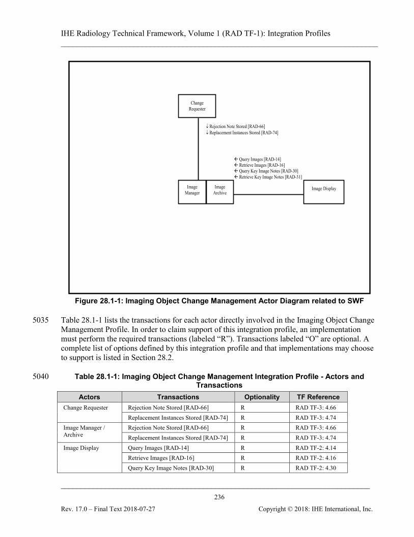
IHE Radiology Technical Framework, Volume 1 (RAD TF-1): Integration Profiles ______________________________________________________________________________
____________________________________________________________________________ 236
Rev. 17.0 – Final Text 2018-07-27 Copyright © 2018: IHE International, Inc.
Change Requester
↓ Rejection Note Stored [RAD-66] ↓ Replacement Instances Stored [RAD-74]
Image Display
Query Images [RAD-14] Retrieve Images [RAD-16] Query Key Image Notes [RAD-30] Retrieve Key Image Notes [RAD-31]
Image Manager
Image Archive
Figure 28.1-1: Imaging Object Change Management Actor Diagram related to SWF
Table 28.1-1 lists the transactions for each actor directly involved in the Imaging Object Change 5035 Management Profile. In order to claim support of this integration profile, an implementation must perform the required transactions (labeled “R”). Transactions labeled “O” are optional. A complete list of options defined by this integration profile and that implementations may choose to support is listed in Section 28.2.
Table 28.1-1: Imaging Object Change Management Integration Profile - Actors and 5040 Transactions
Actors Transactions Optionality TF Reference Change Requester Rejection Note Stored [RAD-66] R RAD TF-3: 4.66
Replacement Instances Stored [RAD-74] R RAD TF-3: 4.74 Image Manager / Archive
Rejection Note Stored [RAD-66] R RAD TF-3: 4.66 Replacement Instances Stored [RAD-74] R RAD TF-3: 4.74
Image Display Query Images [RAD-14] R RAD TF-2: 4.14 Retrieve Images [RAD-16] R RAD TF-2: 4.16 Query Key Image Notes [RAD-30] R RAD TF-2: 4.30
IHE Radiology Technical Framework, Volume 1 (RAD TF-1): Integration Profiles ______________________________________________________________________________
____________________________________________________________________________ 237
Rev. 17.0 – Final Text 2018-07-27 Copyright © 2018: IHE International, Inc.
Actors Transactions Optionality TF Reference Retrieve Key Image Notes [RAD-31] R RAD TF-2: 4.31
28.2 Imaging Object Change Management Integration Profile Options Options that may be selected for this integration profile are listed in the Table 28.2-1 along with the Actors to which they apply. Dependencies between options when applicable are specified in notes. 5045
Table 28.2-1: Imaging Object Change Management - Actors and Options Actor Options TF Reference
Change Requester No option defined -
Image Manager / Archive No option defined - Image Display No option defined -
28.3 Imaging Object Change Management Integration Profile Actor Groupings and Profile Interactions
Imaging Object Change Management builds upon the underlying Actor transactions defined in 5050 other Profiles. For this reason, certain IOCM Profile actors shall be grouped with actors from other Profiles as defined in Table 28.3-1.
Table 28.3-1: Imaging Object Change Management Integration Profile - Actors and Transactions
Integration Profile
Actor Grouped With Comments Profile Actor
Imaging Object Change Management
Change Requester (see note 1)
Scheduled Workflow
Acquisition Modality
Support communication of procedure steps and storage commitment when Change Requester is grouped with Acquisition Modality, Image Manager/Image Archive or Evidence Creator.
Scheduled Workflow
Evidence Creator
Scheduled Workflow
Image Manager/ Image Archive
Defines how Image Manager/Image Archive can obtain scheduled worklist in order to correct the modality worklist selection of the acquired instances.
IHE Radiology Technical Framework, Volume 1 (RAD TF-1): Integration Profiles ______________________________________________________________________________
____________________________________________________________________________ 238
Rev. 17.0 – Final Text 2018-07-27 Copyright © 2018: IHE International, Inc.
Integration Profile
Actor Grouped With Comments Profile Actor
Image Manager/ Image Archive
Scheduled Workflow
Image Manager/ Image Archive
Support Image Manager to Image Manager change management if Multiple Patient Identity Resolution Option is supported.
Image Display Scheduled Workflow
Image Display SWF defines message semantics for query-retrieval
Change Requester (see note 1)
Patient Information Reconciliation
Acquisition Modality
PIR defines the patient information reconciliation mechanisms that shall be supported by these actors. IOCM shall not be used as an alternative mechanism for handling patient information reconciliation use cases.
Patient Information Reconciliation
Image Manager/ Image Archive
Image Manager/ Image Archive
Patient Information Reconciliation
Image Manager/ Image Archive
Note 1: At least one of the optional retrieve transactions is required to be supported. Refer to Section 18.4 for additional 5055 requirements on the Imaging Document Consumer.
28.4 Imaging Object Change Management Process Flow Imaging Object Change Management covers the following use cases:
• Data Retention Expiration
• Correction or Rejection of imaging instances for Quality Reasons 5060
• Correction or Rejection of imaging instances for Patient Safety Reasons
• Correction of Modality Worklist Selection The following use cases generally apply to all imaging objects as well as non-imaging objects including Grayscale Softcopy Presentation State (GSPS), Key Object Selection Document (KOS), Structured Report (SR), etc. although the examples may focus on the images themselves 5065 for simplicity. The start and completion of creating Rejection Notes, and Replacement Instances if necessary, are reported as Procedure Steps In-Progress/Completed by the relevant IHE workflow actor that has been grouped with the Change Requester (either an Acquisition Modality or an Evidence Creator). 5070 The Procedure Step transactions, Storage Commitment transaction, Query Modality Worklist transaction and the Query/ Retrieve Images transactions in the following diagrams are part of
IHE Radiology Technical Framework, Volume 1 (RAD TF-1): Integration Profiles ______________________________________________________________________________
____________________________________________________________________________ 239
Rev. 17.0 – Final Text 2018-07-27 Copyright © 2018: IHE International, Inc.
Radiology Scheduled Workflow as an example IHE Workflow Profile. They are not part of the Imaging Object Change Management Profile and are only included in the diagrams for illustration. 5075
Note: There are existing profiles defined in the Radiology Technical Framework that are also designed to manage changes in different aspects of imaging objects (e.g., Patient Information Reconciliation, Import Reconciliation Workflow, etc.) Vendors should continue to follow those integration profiles for their respective use cases.
28.4.1 Use Case: Data Retention Expiration Instances may be deleted to comply with data retention policies. 5080
• A local Image Manager / Archive, supporting the Multiple Identity Resolution Option in IHE Scheduled Workflow Profile, stores instances to a centralized Image Manager / Archive for long term storage (IHE Radiology Supplement MIMA [RAD-70]).
• Later, according to the data retention policy of the local Image Manager / Archive, selected studies are deleted internally. 5085
• The local Image Manager / Archive has implemented the Change Requester Actor of the IOCM Profile to communicate these changes to the centralized Image Manager / Archive.
• The local Image Manager / Archive, as an IOCM Change Requester, creates a Key Object Selection (KOS) instance with a Selection Document Title of “Data Retention Policy Expired” that lists the deleted instances, and sends this to the centralized Image 5090 Manager / Archive using the [RAD-66] transaction, followed by Storage Commitment [RAD-71].
• The centralized Image Manager / Archive receives the deletion requests and deletes the referenced studies accordingly.
The healthcare provider is responsible for drafting and implementing appropriate data retention 5095 policies (see Section 28.4).
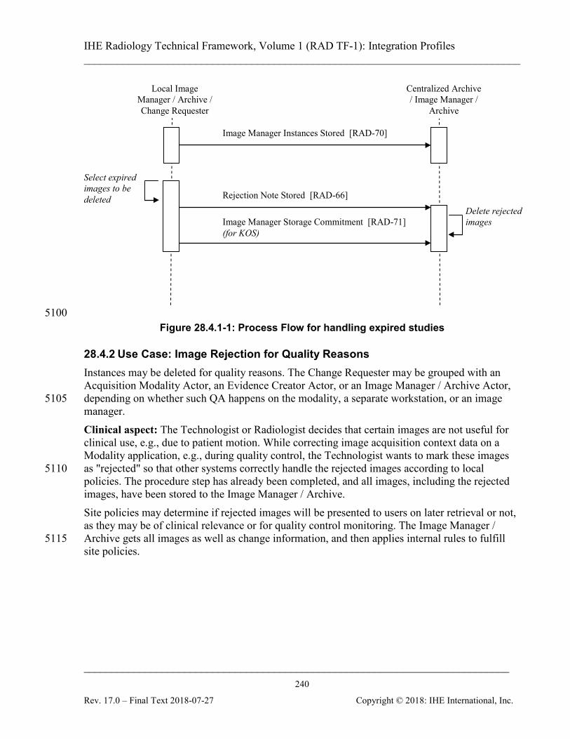
IHE Radiology Technical Framework, Volume 1 (RAD TF-1): Integration Profiles ______________________________________________________________________________
____________________________________________________________________________ 240
Rev. 17.0 – Final Text 2018-07-27 Copyright © 2018: IHE International, Inc.
Local Image Manager / Archive / Change Requester
Centralized Archive / Image Manager /
Archive
Select expired images to be deleted
Delete rejected images
Rejection Note Stored [RAD-66]
Image Manager Storage Commitment [RAD-71] (for KOS)
Image Manager Instances Stored [RAD-70]
5100 Figure 28.4.1-1: Process Flow for handling expired studies
28.4.2 Use Case: Image Rejection for Quality Reasons Instances may be deleted for quality reasons. The Change Requester may be grouped with an Acquisition Modality Actor, an Evidence Creator Actor, or an Image Manager / Archive Actor, depending on whether such QA happens on the modality, a separate workstation, or an image 5105 manager. Clinical aspect: The Technologist or Radiologist decides that certain images are not useful for clinical use, e.g., due to patient motion. While correcting image acquisition context data on a Modality application, e.g., during quality control, the Technologist wants to mark these images as "rejected" so that other systems correctly handle the rejected images according to local 5110 policies. The procedure step has already been completed, and all images, including the rejected images, have been stored to the Image Manager / Archive. Site policies may determine if rejected images will be presented to users on later retrieval or not, as they may be of clinical relevance or for quality control monitoring. The Image Manager / Archive gets all images as well as change information, and then applies internal rules to fulfill 5115 site policies.
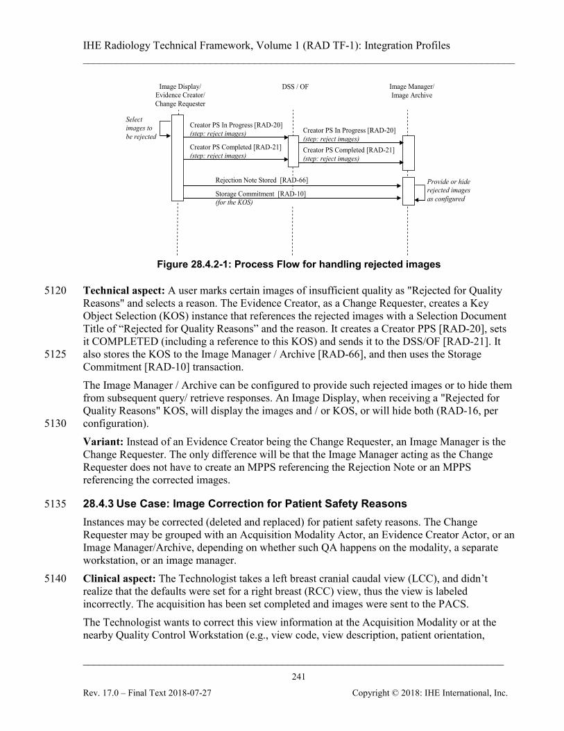
IHE Radiology Technical Framework, Volume 1 (RAD TF-1): Integration Profiles ______________________________________________________________________________
____________________________________________________________________________ 241
Rev. 17.0 – Final Text 2018-07-27 Copyright © 2018: IHE International, Inc.
Image Display/ Evidence Creator/ Change Requester
DSS / OF Image Manager/ Image Archive
Creator PS Completed [RAD-21] (step: reject images)
Select images to be rejected
Creator PS In Progress [RAD-20] (step: reject images)
Creator PS Completed [RAD-21] (step: reject images)
Creator PS In Progress [RAD-20] (step: reject images)
Provide or hide rejected images as configured
Rejection Note Stored [RAD-66]
Storage Commitment [RAD-10] (for the KOS)
Figure 28.4.2-1: Process Flow for handling rejected images
Technical aspect: A user marks certain images of insufficient quality as "Rejected for Quality 5120 Reasons" and selects a reason. The Evidence Creator, as a Change Requester, creates a Key Object Selection (KOS) instance that references the rejected images with a Selection Document Title of “Rejected for Quality Reasons” and the reason. It creates a Creator PPS [RAD-20], sets it COMPLETED (including a reference to this KOS) and sends it to the DSS/OF [RAD-21]. It also stores the KOS to the Image Manager / Archive [RAD-66], and then uses the Storage 5125 Commitment [RAD-10] transaction. The Image Manager / Archive can be configured to provide such rejected images or to hide them from subsequent query/ retrieve responses. An Image Display, when receiving a "Rejected for Quality Reasons" KOS, will display the images and / or KOS, or will hide both (RAD-16, per configuration). 5130 Variant: Instead of an Evidence Creator being the Change Requester, an Image Manager is the Change Requester. The only difference will be that the Image Manager acting as the Change Requester does not have to create an MPPS referencing the Rejection Note or an MPPS referencing the corrected images.
28.4.3 Use Case: Image Correction for Patient Safety Reasons 5135 Instances may be corrected (deleted and replaced) for patient safety reasons. The Change Requester may be grouped with an Acquisition Modality Actor, an Evidence Creator Actor, or an Image Manager/Archive, depending on whether such QA happens on the modality, a separate workstation, or an image manager. Clinical aspect: The Technologist takes a left breast cranial caudal view (LCC), and didn’t 5140 realize that the defaults were set for a right breast (RCC) view, thus the view is labeled incorrectly. The acquisition has been set completed and images were sent to the PACS. The Technologist wants to correct this view information at the Acquisition Modality or at the nearby Quality Control Workstation (e.g., view code, view description, patient orientation,
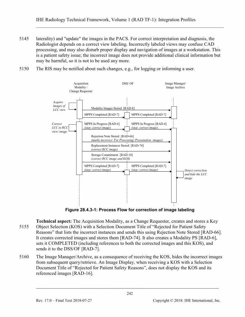
IHE Radiology Technical Framework, Volume 1 (RAD TF-1): Integration Profiles ______________________________________________________________________________
____________________________________________________________________________ 242
Rev. 17.0 – Final Text 2018-07-27 Copyright © 2018: IHE International, Inc.
laterality) and "update" the images in the PACS. For correct interpretation and diagnosis, the 5145 Radiologist depends on a correct view labeling. Incorrectly labeled views may confuse CAD processing, and may also disturb proper display and navigation of images at a workstation. This is a patient safety issue; the incorrect image does not provide additional clinical information but may be harmful, so it is not to be used any more. The RIS may be notified about such changes, e.g., for logging or informing a user. 5150
Acquisition Modality /
Change Requester
DSS/ OF Image Manager/ Image Archive
MPPS Completed [RAD-7] (step: correct image)
Correct LCC to RCC view/ image
Modality Images Stored [RAD-8]
Acquire images of LCC view
MPPS Completed [RAD-7]
Replacement Instances Stored [RAD-74] (correct RCC image)
MPPS In Progress [RAD-6] (step: correct image)
MPPS Completed [RAD-7]
MPPS Completed [RAD-7] (step: correct image)
MPPS In Progress [RAD-6] (step: correct image)
Detect correction and hide the LCC image
Rejection Note Stored [RAD-66] (marks incorrect For Processing/ Presentation images)
Storage Commitment [RAD-10] (correct RCC image and KOS)
Figure 28.4.3-1: Process Flow for correction of image labeling
Technical aspect: The Acquisition Modality, as a Change Requester, creates and stores a Key Object Selection (KOS) with a Selection Document Title of “Rejected for Patient Safety 5155 Reasons” that lists the incorrect instances and sends this using Rejection Note Stored [RAD-66]. It creates corrected images and stores them [RAD-74]. It also creates a Modality PS [RAD-6], sets it COMPLETED (including references to both the corrected images and this KOS), and sends it to the DSS/OF [RAD-7]. The Image Manager/Archive, as a consequence of receiving the KOS, hides the incorrect images 5160 from subsequent query/retrieve. An Image Display, when receiving a KOS with a Selection Document Title of “Rejected for Patient Safety Reasons”, does not display the KOS and its referenced images [RAD-16].
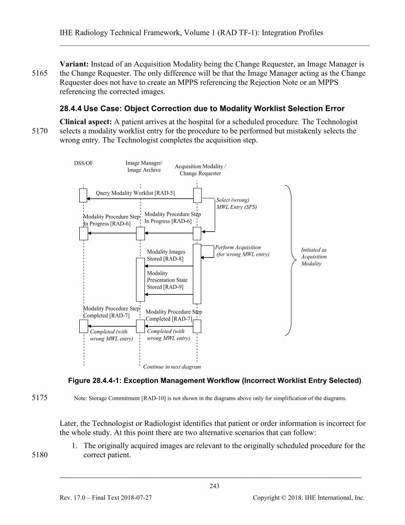
IHE Radiology Technical Framework, Volume 1 (RAD TF-1): Integration Profiles ______________________________________________________________________________
____________________________________________________________________________ 243
Rev. 17.0 – Final Text 2018-07-27 Copyright © 2018: IHE International, Inc.
Variant: Instead of an Acquisition Modality being the Change Requester, an Image Manager is the Change Requester. The only difference will be that the Image Manager acting as the Change 5165 Requester does not have to create an MPPS referencing the Rejection Note or an MPPS referencing the corrected images.
28.4.4 Use Case: Object Correction due to Modality Worklist Selection Error Clinical aspect: A patient arrives at the hospital for a scheduled procedure. The Technologist selects a modality worklist entry for the procedure to be performed but mistakenly selects the 5170 wrong entry. The Technologist completes the acquisition step. Image Manager/
Image Archive Acquisition Modality / Change Requester
DSS/OF
Perform Acquisition (for wrong MWL entry) Modality Images
Stored [RAD-8]
Modality Presentation State Stored [RAD-9]
Modality Procedure Step Completed [RAD-7]
Modality Procedure Step In Progress [RAD-6]
Query Modality Worklist [RAD-5] Select (wrong) MWL Entry (SPS)
Completed (with wrong MWL entry)
Completed (with wrong MWL entry)
Modality Procedure Step In Progress [RAD-6]
Modality Procedure Step Completed [RAD-7]
Initiated as Acquisition Modality
Continue in next diagram
Figure 28.4.4-1: Exception Management Workflow (Incorrect Worklist Entry Selected)
Note: Storage Commitment [RAD-10] is not shown in the diagrams above only for simplification of the diagrams. 5175 Later, the Technologist or Radiologist identifies that patient or order information is incorrect for the whole study. At this point there are two alternative scenarios that can follow:
1. The originally acquired images are relevant to the originally scheduled procedure for the correct patient. 5180
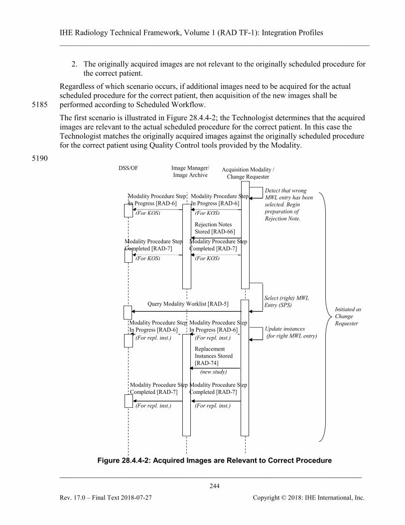
IHE Radiology Technical Framework, Volume 1 (RAD TF-1): Integration Profiles ______________________________________________________________________________
____________________________________________________________________________ 244
Rev. 17.0 – Final Text 2018-07-27 Copyright © 2018: IHE International, Inc.
2. The originally acquired images are not relevant to the originally scheduled procedure for the correct patient.
Regardless of which scenario occurs, if additional images need to be acquired for the actual scheduled procedure for the correct patient, then acquisition of the new images shall be performed according to Scheduled Workflow. 5185 The first scenario is illustrated in Figure 28.4.4-2; the Technologist determines that the acquired images are relevant to the actual scheduled procedure for the correct patient. In this case the Technologist matches the originally acquired images against the originally scheduled procedure for the correct patient using Quality Control tools provided by the Modality. 5190 Image Manager/
Image Archive Acquisition Modality /
Change Requester DSS/OF
Update instances (for right MWL entry)
Rejection Notes Stored [RAD-66]
Replacement Instances Stored [RAD-74]
Select (right) MWL Entry (SPS) Query Modality Worklist [RAD-5]
Modality Procedure Step In Progress [RAD-6]
Modality Procedure Step In Progress [RAD-6]
Modality Procedure Step In Progress [RAD-6]
Modality Procedure Step In Progress [RAD-6]
Detect that wrong MWL entry has been selected. Begin preparation of Rejection Note.
Initiated as Change Requester
(new study)
Modality Procedure Step Completed [RAD-7]
Modality Procedure Step Completed [RAD-7]
Modality Procedure Step Completed [RAD-7]
Modality Procedure Step Completed [RAD-7]
(For KOS) (For KOS)
(For KOS) (For KOS)
(For repl. inst.) (For repl. inst.)
(For repl. inst.) (For repl. inst.)
Figure 28.4.4-2: Acquired Images are Relevant to Correct Procedure
IHE Radiology Technical Framework, Volume 1 (RAD TF-1): Integration Profiles ______________________________________________________________________________
____________________________________________________________________________ 245
Rev. 17.0 – Final Text 2018-07-27 Copyright © 2018: IHE International, Inc.
Note: Storage Commitment [RAD-10] is not shown in the diagrams above only for simplification of the diagrams.
The alternative scenario is that the Technologist determines that the originally acquired images 5195 are not relevant to the actual scheduled procedure for the correct patient. This could be handled in two different ways:
1. The originally acquired images are handled by the Technologist as an unscheduled case. 2. A new procedure is scheduled for the correct patient on the DSS/OF and the originally
acquired images are updated to correspond to the new scheduled procedure obtained from 5200 the Modality Worklist.
Figure 28.4.4-3 illustrates the correction of the images as an unscheduled case. The alternative approach of scheduling a new procedure on the DSS/OF is not illustrated here. It would follow the normal Scheduled Workflow sequencing with the exception that rather than acquiring new images, the originally acquired images would be updated to correspond to the new 5205 scheduled procedure obtained from the Modality Worklist.
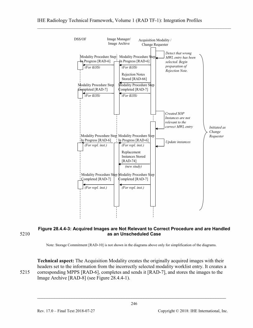
IHE Radiology Technical Framework, Volume 1 (RAD TF-1): Integration Profiles ______________________________________________________________________________
____________________________________________________________________________ 246
Rev. 17.0 – Final Text 2018-07-27 Copyright © 2018: IHE International, Inc.
Image Manager/ Image Archive
Acquisition Modality / Change Requester
DSS/OF
Update instances
Rejection Notes Stored [RAD-66]
Replacement Instances Stored [RAD-74]
Created SOP Instances are not relevant to the correct MWL entry
Modality Procedure Step In Progress [RAD-6]
Modality Procedure Step In Progress [RAD-6]
Modality Procedure Step In Progress [RAD-6]
Modality Procedure Step In Progress [RAD-6]
Detect that wrong MWL entry has been selected. Begin preparation of Rejection Note.
Initiated as Change Requester
(new study)
Modality Procedure Step Completed [RAD-7]
Modality Procedure Step Completed [RAD-7]
Modality Procedure Step Completed [RAD-7]
Modality Procedure Step Completed [RAD-7]
(For KOS) (For KOS)
(For KOS) (For KOS)
(For repl. inst.) (For repl. inst.)
(For repl. inst.) (For repl. inst.)
Figure 28.4.4-3: Acquired Images are Not Relevant to Correct Procedure and are Handled
as an Unscheduled Case 5210
Note: Storage Commitment [RAD-10] is not shown in the diagrams above only for simplification of the diagrams.
Technical aspect: The Acquisition Modality creates the originally acquired images with their headers set to the information from the incorrectly selected modality worklist entry. It creates a corresponding MPPS [RAD-6], completes and sends it [RAD-7], and stores the images to the 5215 Image Archive [RAD-8] (see Figure 28.4.4-1).
IHE Radiology Technical Framework, Volume 1 (RAD TF-1): Integration Profiles ______________________________________________________________________________
____________________________________________________________________________ 247
Rev. 17.0 – Final Text 2018-07-27 Copyright © 2018: IHE International, Inc.
Later, the Technologist or the Radiologist detects the mistakes (see Figure 28.4.4-2). The Acquisition Modality, as a Change Requester, sends a Rejection Note [RAD-66] KOS which contains references to the rejected SOP instances, the originally acquired images, to the Image Manager. It also creates a MPPS (RAD-6) referencing this Rejection Note, completes the MPPS 5220 with the reference to the KOS and sends it to the Image Manager / Archive and DSS/OF [RAD-7]. The Image Manager receives the Rejection Note and makes all the referenced SOP instances unavailable. The technical aspects then vary depending upon whether or not the originally acquired images are relevant to the actual scheduled procedure for the correct patient. 5225 If it is determined that the originally acquired images are relevant to the actual scheduled procedure for the correct patient then the Acquisition Modality selects the correct modality worklist entry [RAD-5] and updates the originally acquired images (while the study is still available at the Acquisition Modality without re-acquisition) with the correct information. The corrected images are assigned new SOP Instance UIDs so that they can be distinguished from the 5230 originally acquired images which have already been exported. If the correct modality worklist entry is not readily available, the Acquisition Modality queries the DSS/OF again, as illustrated in Figure 28.4.4-2. In order to communicate the corrected images to other systems, the Acquisition Modality, as a Change Requester, creates a new MPPS with the correct information from the modality worklist [RAD-5]. It then stores the new set of corrected images to the Image 5235 Manager [RAD-74], and completes the MPPS and sends it [RAD-7]. Alternatively, if it is determined that the originally acquired images are not relevant to the actual scheduled procedure for the correct patient then the Acquisition Modality either handles the images as if they belong to an unscheduled procedure, or a new procedure for the acquired images is entered on the DSS/OF. If treated as an unscheduled case as shown in Figure 28.4.4-3, 5240 then there is no modality worklist entry to associate the originally acquired images with. The images would thus require manual correction on the Acquisition Modality. The corrected images are assigned new SOP Instance UIDs so that they can be distinguished from the originally acquired images which have already been exported. In order to communicate the corrected images to other systems, the Acquisition Modality, as a Change Requester, creates a new MPPS. 5245 It then stores the new set of corrected images with manually corrected headers to the Image Manager [RAD-74], completes the MPPS and sends it [RAD-7]. Instead of being handled as an unscheduled case, a new procedure could be scheduled on the DSS/OF. In this case the technical aspects would follow the normal Scheduled Workflow sequencing with the exception that, rather than acquiring new images, the originally acquired 5250 images would be updated to correspond to the new scheduled procedure obtained from the Modality Worklist.
Note: IHE Scheduled Workflow Profile defines an PPS Exception Management Option (RAD TF-1:3.3.4 and RAD TF-2:4.7.4.1.3.1) which specifies how to correct the incorrectly selected worklist entry after the Modality Performed Procedure Step In Progress transaction has been issued but before the Modality Performed Procedure Step 5255 Completed transaction is issued. Notice that there is no external component involved in this situation since the acquired images usually have not been shared prior to MPPS complete or discontinued.
IHE Radiology Technical Framework, Volume 1 (RAD TF-1): Integration Profiles ______________________________________________________________________________
____________________________________________________________________________ 248
Rev. 17.0 – Final Text 2018-07-27 Copyright © 2018: IHE International, Inc.
Variant: Instead of an Acquisition Modality being the Change Requester, an Image Manager is the Change Requester. In this case, the Image Manager uses the received procedure information from Procedure Scheduled [RAD-4] and Procedure Updated [RAD-13] to choose the correct 5260 modality worklist, updates the images and creates a new set as described above. The Image Manager does not have to create an MPPS referencing the Rejection Note or an MPPS referencing the corrected images. Variant: Instead of selecting an incorrect modality worklist entry, the Technologist forgets to complete the previous worklist entry before starting the new acquisition. The acquired images 5265 are incorrectly appended to an existing study of a different patient for a different procedure. As a result, the resulting study becomes partially incorrect. Only the incorrect images and/or presentation states are required to be corrected.
28.5 Imaging Object Change Management Security Considerations The section describes the policies for reducing risks after correction or rejection at the Change 5270 Requester. Images that are marked as "rejected" for quality reasons (see Section 28.4.2) may or may not contain clinically relevant information. They may be useful in certain situations. Sites may decide to provide them regularly as part of a Study or may hide them at the Archive or at Workstations. IHE supports such policies by defining configurable behavior at the Image 5275 Manager/ Image Archive for storage and at the Image Display for presentation. Incorrectly labeled images (see Section 28.4.3), e.g., containing a wrong patient orientation or laterality, may mislead image interpretation and thus may be harmful to a patient. For patient safety reasons, they are marked in order to not be used later; an Archive hides such images and does not provide them in IHE-defined query and retrieve transactions. 5280 IHE defines a Key Object Selection document with a special title code as a specific trigger to the Image Manager for hiding incorrect instances (different from general Key Image Note use, RAD TF-1: 8). Note that a central correction mechanism at the Image Manager/ Image Archive decreases the risk for harmful or misleading use of rejected or incorrect images, such images are not included 5285 in regular query results or retrieve transactions, and their presentation does not depend on local configuration of individual workstations. Rarely, race conditions may result from information in archived images that is not yet corrected, e.g., due to latencies from asynchronous messaging. In this case, Image Displays may receive and present inconsistent, incomplete or wrong information. 5290 The correction and rejection mechanisms defined for IHE Imaging Object Change Management Integration Profile will only correctly work in a system environment where each system implements the corresponding Actors from this integration profile. In addition, the Image Manager/ Archive and Displays need to be configured in a way that meets the department or enterprise policies. 5295
IHE Radiology Technical Framework, Volume 1 (RAD TF-1): Integration Profiles ______________________________________________________________________________
____________________________________________________________________________ 249
Rev. 17.0 – Final Text 2018-07-27 Copyright © 2018: IHE International, Inc.
The correction and rejection mechanisms are capable of deleting or changing evidence of a performed procedure. That means a malicious user or system can use this mechanism to hide a mistake. Therefore the audit record should include information about who initiates the correction / rejection as well as the reason of the initiation. Traceability is also available using the Referenced Instance Sequence (see RAD TF-3:4.74.4.1.2) in the header of the replacement 5300 instances. Since any actor can group with the Change Requester, it is important for the Image Manager / Archive to validate the source and authority of the Change Requester before rejecting any referenced instances in the KOS. For example, the Image Manager / Archive can restrict rejection of instances referenced in the received KOS if and only if the KOS is sent from the 5305 same DICOM Application Entity as the original instances.
IHE Radiology Technical Framework, Volume 1 (RAD TF-1): Integration Profiles ______________________________________________________________________________
____________________________________________________________________________ 250
Rev. 17.0 – Final Text 2018-07-27 Copyright © 2018: IHE International, Inc.
29 Cross-Community Access for Imaging (XCA-I) The Cross-Community Access for Imaging (XCA-I) Integration Profile specifies actors and transactions to query and retrieve patient-relevant medical imaging data being held by other communities. 5310 Within a community, a group of facilities/enterprises shares clinical information via an established mechanism such as XDS-I (in which case the community can be referred to as an XDS Affinity Domain). This profile addresses sharing between such communities. The XCA-I Profile extends the IT Infrastructure XCA Profile. XCA provides access to Diagnostic reports and Imaging Manifests. XCA-I provides access to the imaging objects 5315 referenced in the Manifests. The reader of XCA-I is expected to have read and understood the XCA Profile, including the meaning of terms such as Community, homeCommunityId, etc.
29.1 Actors/ Transactions Figure 29.1-1 shows the actors defined in the Cross-Community Access for Imaging (XCA-I) Profile and the transactions between them. 5320 The shaded actors are NOT included in this profile but are shown to illustrate the full set of actors that play a role other endpoint of transactions that ARE part of the profile (e.g., the Document Registry Actor is an endpoint for the Registry Stored Query [ITI-18] transaction). As a result, the shaded actors are not listed in Table 29.1-1. 5325 5330 5335
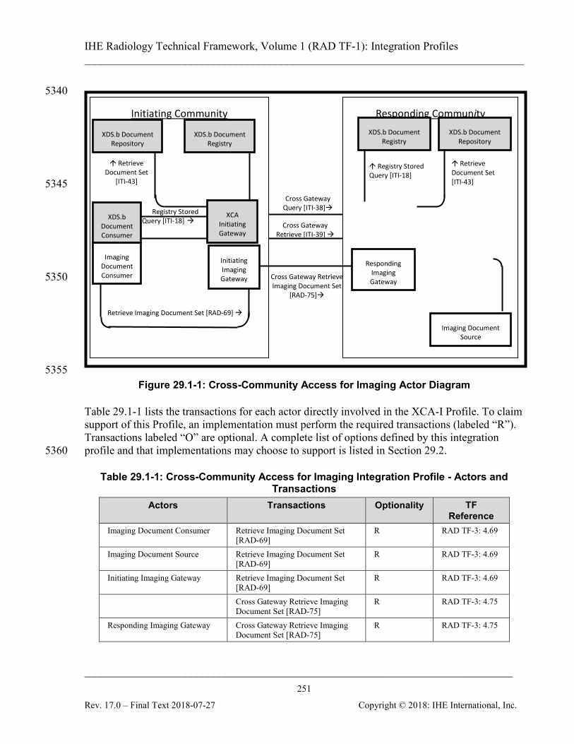
IHE Radiology Technical Framework, Volume 1 (RAD TF-1): Integration Profiles ______________________________________________________________________________
____________________________________________________________________________ 251
Rev. 17.0 – Final Text 2018-07-27 Copyright © 2018: IHE International, Inc.
5340 5345 5350
5355
Figure 29.1-1: Cross-Community Access for Imaging Actor Diagram
Table 29.1-1 lists the transactions for each actor directly involved in the XCA-I Profile. To claim support of this Profile, an implementation must perform the required transactions (labeled “R”). Transactions labeled “O” are optional. A complete list of options defined by this integration profile and that implementations may choose to support is listed in Section 29.2. 5360
Table 29.1-1: Cross-Community Access for Imaging Integration Profile - Actors and Transactions
Actors Transactions Optionality TF Reference
Imaging Document Consumer Retrieve Imaging Document Set [RAD-69]
R RAD TF-3: 4.69
Imaging Document Source Retrieve Imaging Document Set [RAD-69]
R RAD TF-3: 4.69
Initiating Imaging Gateway Retrieve Imaging Document Set [RAD-69]
R RAD TF-3: 4.69
Cross Gateway Retrieve Imaging Document Set [RAD-75]
R RAD TF-3: 4.75
Responding Imaging Gateway Cross Gateway Retrieve Imaging Document Set [RAD-75]
R RAD TF-3: 4.75
Registry Stored Query [ITI-18]
Cross Gateway Retrieve Imaging Document Set
[RAD-75]
Registry Stored Query [ITI-18]
Retrieve Document Set
[ITI-43]
Cross Gateway Retrieve [ITI-39]
Cross Gateway Query [ITI-38]
XCA Responding
Gateway
Retrieve Imaging Document Set [RAD-69] ↓
Responding Community Initiating Community XDS.b Document
Repository
Imaging Document Source
XDS.b Document Registry
Registry Stored Query [ITI-18]
Retrieve Document Set [ITI-43]
Responding Imaging Gateway
Retrieve Imaging Document Set [RAD-69]
Retrieve Document Set
[ITI-43]
XDS.b Document Registry
XDS.b Document Repository
XCA Initiating Gateway
Initiating Imaging Gateway
XDS.b Document Consumer
Imaging Document Consumer
Registry Stored Query [ITI-18]
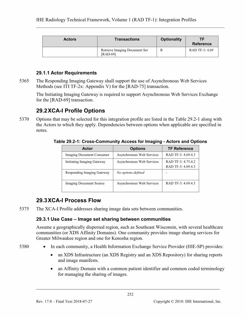
IHE Radiology Technical Framework, Volume 1 (RAD TF-1): Integration Profiles ______________________________________________________________________________
____________________________________________________________________________ 252
Rev. 17.0 – Final Text 2018-07-27 Copyright © 2018: IHE International, Inc.
Actors Transactions Optionality TF Reference
Retrieve Imaging Document Set [RAD-69]
R RAD TF-3: 4.69
29.1.1 Actor Requirements The Responding Imaging Gateway shall support the use of Asynchronous Web Services 5365 Methods (see ITI TF-2x: Appendix V) for the [RAD-75] transaction. The Initiating Imaging Gateway is required to support Asynchronous Web Services Exchange for the [RAD-69] transaction.
29.2 XCA-I Profile Options Options that may be selected for this integration profile are listed in the Table 29.2-1 along with 5370 the Actors to which they apply. Dependencies between options when applicable are specified in notes.
Table 29.2-1: Cross-Community Access for Imaging - Actors and Options Actor Options TF Reference
Imaging Document Consumer Asynchronous Web Services RAD TF-3: 4.69.4.3
Initiating Imaging Gateway Asynchronous Web Services RAD TF-3: 4.75.4.2 RAD TF-3: 4.69.4.3
Responding Imaging Gateway No options defined -
Imaging Document Source Asynchronous Web Services RAD TF-3: 4.69.4.3
29.3 XCA-I Process Flow The XCA-I Profile addresses sharing image data sets between communities. 5375
29.3.1 Use Case – Image set sharing between communities Assume a geographically dispersed region, such as Southeast Wisconsin, with several healthcare communities (or XDS Affinity Domains). One community provides image sharing services for Greater Milwaukee region and one for Kenosha region.
• In each community, a Health Information Exchange Service Provider (HIE-SP) provides: 5380
• an XDS Infrastructure (an XDS Registry and an XDS Repository) for sharing reports and image manifests.
• an Affinity Domain with a common patient identifier and common coded terminology for managing the sharing of images.
IHE Radiology Technical Framework, Volume 1 (RAD TF-1): Integration Profiles ______________________________________________________________________________
____________________________________________________________________________ 253
Rev. 17.0 – Final Text 2018-07-27 Copyright © 2018: IHE International, Inc.
• In each community, Diagnostic Imaging Service Providers provide access to locally 5385 stored images through transactions defined by the XDS-I.b Integration Profile.
• Two communities agree to share patient records for urgent care using transactions defined in XCA-I.
A patient X, who receives her primary care in Kenosha, frequently travels to the Greater Milwaukee region for business. While visiting Milwaukee, patient X is admitted to the 5390 Milwaukee University Hospital (MUH) for urgent care. The attending physician places an imaging procedure order. The local PACS, acting as an XDS-I.b Imaging Document Consumer, performs an automated query for relevant priors within the Greater Milwaukee region and to the Kenosha region through an XDS.b Stored Query transaction to the local HIE-SP’s Initiating Gateway. 5395 The Initiating Gateway in Greater Milwaukee queries both the local Document Registry and the Responding Gateway for Kenosha. Relevant priors are located in Kenosha and in the South Milwaukee Diagnostic Imaging Center. The South Milwaukee Diagnostic Imaging Center shares images using XDS-I.b as part of the Greater Milwaukee region. The MUH PACS, acting as an XDS-I.b Imaging Document Consumer, directly accesses images 5400 from the South Milwaukee Diagnostic Imaging Center via their XDS I.b Imaging Document Source. Images from the Kenosha region are retrieved through the Greater Milwaukee HIE-SP’s XCA-I Initiating Imaging Gateway, retrieving the images from the Kenosha HIE-SP’s XCA-I Responding Imaging Gateway. The Kenosha HIE-SP XCA-I Responding Imaging Gateway, in 5405 turn, retrieves the images from Imaging Document Source imaging repositories in the Kenosha region.
29.3.2 Detailed Interactions The following diagram presents a high level view of the interactions between actors when both initiating and responding communities are XDS-I.b Affinity Domains. Details on each 5410 interaction follow the diagram.

IHE Radiology Technical Framework, Volume 1 (RAD TF-1): Integration Profiles ______________________________________________________________________________
____________________________________________________________________________ 254
Rev. 17.0 – Final Text 2018-07-27 Copyright © 2018: IHE International, Inc.
Figure 29.3.2-1: XCA-I Detailed Interactions
Query across Local Community A and Remote Community: Document Consumer initiates a Registry Stored Query request by patient id – the Document Consumer initiates the initial 5415 transaction by formatting a Registry Stored Query request by patient identifier. The consumer uses PDQ, PIX or some other means to identify the Local Affinity Domain patient id, formats that information plus any other query parameters into a Registry Stored Query request and sends this request to an Initiating Gateway. Initiating Gateway processes Registry Stored Query by patient id request – The Initiating 5420 Gateway receives a Registry Stored Query by patient id and must determine a) Which Responding Gateways this request should be sent to b) What patient id to use in the Cross Gateway Queries. Detailed specification of these steps is
not in the intended scope of this profile. Combination of this profile with other existing profiles (e.g., XCPD, PIX/PDQ), future profiles or configuration mechanisms is possible. 5425
IHE Radiology Technical Framework, Volume 1 (RAD TF-1): Integration Profiles ______________________________________________________________________________
____________________________________________________________________________ 255
Rev. 17.0 – Final Text 2018-07-27 Copyright © 2018: IHE International, Inc.
Please refer to ITI TF-2x: E.7 XCA and Patient Identification Management for possible use of existing ITI PIX and PDQ Profiles.
For each Responding Gateway identified, the Initiating Gateway initiates a Cross Gateway Query transaction. The Initiating Gateway also initiates a Registry Stored Query to the local Document Registry. 5430 Responding Gateway processes Cross Gateway Query by patient id – The Responding Gateway processes the Cross Gateway Query by initiating a Registry Stored Query to the local Document Registry. The Responding Gateway updates the response from the Document Registry to ensure that the homeCommunityId is specified on every applicable element. This updated response is sent as the response to the Cross Gateway Query. 5435 Initiating Gateway processes Cross Gateway Query by patient id responses – The Initiating Gateway collects the responses from all Responding Gateways it contacted. For each response it verifies that the homeCommunityId is present in each appropriate element. Once all responses are received the Initiating Gateway consolidates all updated response data into one response to the Document Consumer. The Initiating Gateway returns to the Document Consumer the same 5440 homeCommunityId attribute values that it received from Responding Gateway(s). Document Consumer receives Registry Stored Query by patient id response – The Document Consumer receives the results of the query from the Initiating Gateway and must account for three unique aspects of the response; namely that a) the homeCommunityId attribute will be specified, b) the Document Consumer may not be able to map the repositoryUniqueId value 5445 directly to a Document Repository located in a remote community, and c) the Document Consumer may not be able to understand the terminology used in the response. For example, if the initiating and responding community have common Requested Procedure vocabularies, then the Initiating Gateway will respond to the Document Consumer’s request using the common coding/vocabulary scheme. The Document Consumer retains the values of the 5450 homeCommunityId attribute for future interaction with the Initiating Gateway. Retrieve Image Manifest and Reports from local Community A & Remote Community B: Document Consumer initiates a Retrieve Document Set – If the Document Consumer issued a Registry Stored Query, the response to the Registry Stored Query by patient id includes a) the document uniqueId b) the repositoryUniqueId, and c) the homeCommunityId attribute. The 5455 Document Consumer shall specify these three parameters in its Retrieve Document Set transaction to the Initiating Gateway. Initiating Gateway processes Retrieve Document Set – The Initiating Gateway determines which Responding Gateway(s) to contact by using the homeCommunityId to obtain the Web Services endpoint of the Responding Gateway(s). If the homeCommunityId represents the local 5460 community, the Initiating Gateway will initiate a Retrieve Document Set to the indicated local Document Repository. The Retrieve Document Set may contain more than one unique homeCommunityId so the Initiating Gateway may have to initiate requests to more than one Responding Gateway, and consolidate the results. The Initiating Gateway specifies the homeCommunityId in the Cross Gateway Retrieve transaction. The homeCommunityId 5465 identifies the community associated with the Responding Gateway.

IHE Radiology Technical Framework, Volume 1 (RAD TF-1): Integration Profiles ______________________________________________________________________________
____________________________________________________________________________ 256
Rev. 17.0 – Final Text 2018-07-27 Copyright © 2018: IHE International, Inc.
Responding Gateway processes Cross Gateway Retrieve– The Responding Gateway within an XDS Affinity Domain processes the Cross Gateway Retrieve initiating a Retrieve Document Set transaction to the Document Repository identified by the repositoryUniqueId within the request. If the Cross Gateway Retrieve requests multiple documents with different repositoryUniqueIds, 5470 the Responding Gateway will contact multiple Document Repositories and consolidate the responses. Retrieve Image Set from Remote Community B Imaging Document Consumer initiates a Retrieve Imaging Document Set. The request includes a) the repositoryUniqueId identifying the Imaging Document Source, b) the documentUniqueIds 5475 identifying the imaging documents (DICOM SOP Instance UIDs) within the Imaging Document Source c) list of one or more DICOM transfer syntax UIDs, d) Study Instance UID, e) Series Instance UID f) the homeCommunityId attribute. The Imaging Document Consumer specifies these parameters in its Retrieve Imaging Document Set transaction to the Initiating Imaging Gateway. 5480 Initiating Imaging Gateway processes Retrieve Imaging Document Set – The Initiating Imaging Gateway determines which Responding Imaging Gateways to contact by using the homeCommunityId to obtain the Web Services endpoint of the Responding Imaging Gateway. The Retrieve Imaging Document Set may contain more than one unique homeCommunityId so the Initiating Imaging Gateway may have to initiate requests to more than one Responding 5485 Imaging Gateway, and consolidate the results. The Initiating Imaging Gateway specifies the homeCommunityId in the Cross Gateway Retrieve Imaging Document Set transaction. The homeCommunityId identifies the community associated with the Responding Imaging Gateway. Responding Imaging Gateway processes Cross Gateway Retrieve Imaging Document Set – The Responding Imaging Gateway within an XDS Affinity Domain processes the Cross Gateway 5490 Retrieve Imaging Document Set request by initiating a Retrieve Imaging Document Set transaction to the Imaging Document Source identified by the repositoryUniqueId within the request. If the Cross Gateway Retrieve Imaging Document Set requests multiple documents with different repositoryUniqueIds, the Responding Imaging Gateway will contact multiple Imaging Document Sources and consolidate the responses. 5495 Retrieve Image Set from Local Community A Imaging Document Consumer initiates a Retrieve Imaging Document Set – The request includes a) the repositoryUniqueId identifying the Imaging Document Source, b) the documentUniqueIds identifying the documents (DICOM SOP Instance UIDs) within the Imaging Document Source c) list of one or more DICOM transfer syntax UIDs, d) Study Instance UID, e) 5500 Series Instance UID f) the homeCommunityId attribute. Because the homeCommunityId represents the local community, the Imaging Document Consumer will initiate a Retrieve Imaging Document Set to the local Imaging Document Source.
29.3.3 Actor Grouping Considerations XCA-I presumes the community uses the XDS-I.b and XDS.b integration profiles for enabling 5505 Imaging Document Set behavior. XCA-I defines no required grouping with any actor. The
IHE Radiology Technical Framework, Volume 1 (RAD TF-1): Integration Profiles ______________________________________________________________________________
____________________________________________________________________________ 257
Rev. 17.0 – Final Text 2018-07-27 Copyright © 2018: IHE International, Inc.
implementer may consider grouping actors as needed. For example, an Image Document Source may choose to group with an IRWF Importer for importing images. The XCA-I Profile does not explicitly group the XCA-I Initiating Imaging Gateway and XCA Initiating Gateway pair and the XCA-I Responding Imaging Gateway and XCA Responding Gateway pair. 5510 The XCA-I Profile requires that the Initiating and Responding Imaging Gateways that are used in conjunction with the XCA Initiating and Responding Gateways and will be part of XDS communities that support XDS.b.
29.4 XCA-I Security Considerations
29.4.1 XCA Risk Assessment 5515 The risk analysis for XCA enumerates assets, threats, and mitigations. The complete risk data is stored and maintained in a central location. The complete risk data is stored and available from IHE4. The risks associated with the data content and protocols of [RAD-69] and [RAD-75] are a subset of those identified for the transactions in the ITI XCA Profile. 5520
29.4.2 Requirements/Recommendations The following mitigations shall be implemented by all XCA-I actors. These mitigations moderate all high impact risks. M1: All actors in XCA-I shall be grouped with an ATNA Secure Node or Secure Application Actor and a CT Time Client Actor. 5525 M2: An Imaging Document Source shall include a SHA1 hash of the image document content in the Document metadata of the [RAD-68] response. The Imaging Document Consumer shall have the ability to verify the SHA1 hash of the image document with the SHA1 hash in the metadata. M3: Imaging Document Consumer implementations shall handle overloading through excessive volume of response data by discontinuing the read on the socket and closing it. The Initiating and 5530 Responding Imaging Gateways shall respond to disconnection by discontinuing processing of responses. M6: The Responding Imaging Gateway shall return either zero documents with no further information or XDSUnknownPatientId in response to queries of unknown patient identifiers, depending on local policy. This applies to patient identifiers that are properly formatted or 5535 improperly formatted. By not using an error code indicating that the identifier is ill formatted, you are able to reduce the ability of applications to fish for data.
4 The risk analysis data may be found at: ftp://ftp.ihe.net/IT_Infrastructure/iheitiyr5-2007-2008/Technical_Cmte/Profile_Work/XC/XCARiskAnalysis.xls
IHE Radiology Technical Framework, Volume 1 (RAD TF-1): Integration Profiles ______________________________________________________________________________
____________________________________________________________________________ 258
Rev. 17.0 – Final Text 2018-07-27 Copyright © 2018: IHE International, Inc.
The following mitigations address the risk of a document being maliciously changed. This mitigation is optional. 5540 M5: Documents may be digitally signed using the ITI Digital Signature (DSG) Profile The following mitigations are transferred to the vendors, XDS Affinity Domains, and enterprises. T1: Backup systems for registry metadata, repository documents, and gateway configuration are 5545 recommended. T2: All implementations are recommended to ensure that all received data is propagated appropriately (i.e., without corruption and complete results) or an error is presented. T3: Network protection services are recommended to be sufficient to guard against denial of service attacks on all service interfaces. 5550 T4: A process that reviews audit records and acts on inappropriate actions is recommended. T5: It is recommended that service interfaces be implemented with a good design to guard against corruption and denial of service attacks
29.4.3 Policy Choices Security and privacy policy choices will not be addressed by this profile. Each community may 5555 have different security and privacy policies. The profile has been designed with this fact in mind and an understanding of enough variety of policies so that any reasonable policy can be implemented without violating the profile.
30 Post Acquisition Workflow (PAWF) This section intentionally, temporarily left blank. 5560
31 Cross-Enterprise Reliable Document Interchange – Imaging (XDR-I)
This section intentionally, temporarily left blank.
32 Stereotactic Mammography Image (SMI) This section intentionally, temporarily left blank. 5565
33 Management of Radiology Report Templates (MRRT) This section intentionally, temporarily left blank.
34 Scheduled Workflow.b (SWF.b) This section intentionally, temporarily left blank.

IHE Radiology Technical Framework, Volume 1 (RAD TF-1): Integration Profiles ______________________________________________________________________________
____________________________________________________________________________ 259
Rev. 17.0 – Final Text 2018-07-27 Copyright © 2018: IHE International, Inc.
35 Invoke Image Display (IID) 5570
This section intentionally, temporarily left blank.
36 Temporarily left blank This section intentionally, temporarily left blank.
IHE Radiology Technical Framework, Volume 1 (RAD TF-1): Integration Profiles ______________________________________________________________________________
____________________________________________________________________________ 260
Rev. 17.0 – Final Text 2018-07-27 Copyright © 2018: IHE International, Inc.
37 Digital Breast Tomosynthesis (DBT) 5575
The Digital Breast Tomosynthesis (DBT) Profile specifies the creation, exchange and use of DBT images. It defines basic display capabilities that Image Displays are expected to provide, especially simultaneous review of DBT and conventional 2D mammography images (FFDM). The Digital Breast Tomosynthesis Profile is designed to provide faithful storage and retrieval of DBT images. Furthermore, sufficient display functionality to allow adequate review of current 5580 and prior studies consisting of DBT and/or conventional 2D mammography images is defined. The support for CAD is out of the scope for this profile.
37.1 DBT Actors, Transactions, and Content Modules This section defines the actors, transactions, and/or content modules in this profile. Figure 37.1-1 shows the actors directly involved in the Digital Breast Tomosynthesis Profile and 5585 the relevant transactions between them. If needed for context, other actors that may be indirectly involved due to their participation in other related profiles are shown in dotted lines. Actors which have a mandatory grouping are shown in conjoined boxes.
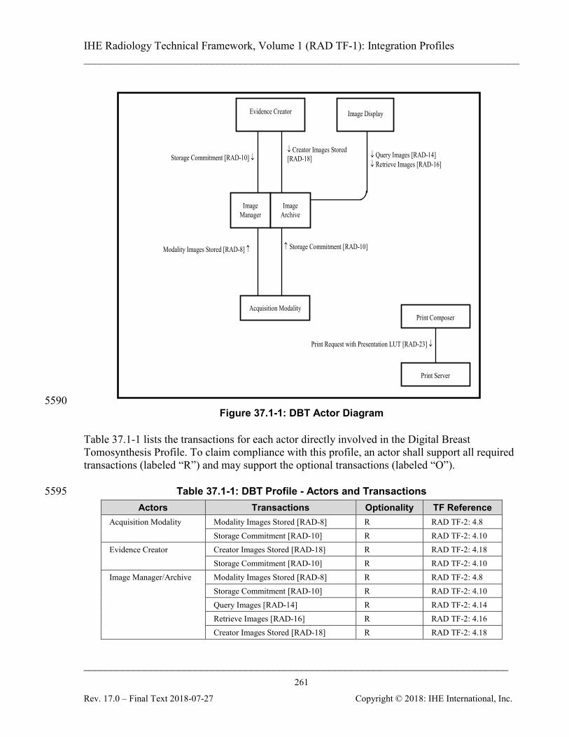
IHE Radiology Technical Framework, Volume 1 (RAD TF-1): Integration Profiles ______________________________________________________________________________
____________________________________________________________________________ 261
Rev. 17.0 – Final Text 2018-07-27 Copyright © 2018: IHE International, Inc.
↓ Query Images [RAD-14] ↓ Retrieve Images [RAD-16]
Modality Images Stored [RAD-8] ↑
Print Request with Presentation LUT [RAD-23] ↓
Print Server
Print Composer
↓ Creator Images Stored [RAD-18] Storage Commitment [RAD-10] ↓
↑ Storage Commitment [RAD-10]
Acquisition Modality
Image Manager
Image Archive
Image Display Evidence Creator
5590 Figure 37.1-1: DBT Actor Diagram
Table 37.1-1 lists the transactions for each actor directly involved in the Digital Breast Tomosynthesis Profile. To claim compliance with this profile, an actor shall support all required transactions (labeled “R”) and may support the optional transactions (labeled “O”).
Table 37.1-1: DBT Profile - Actors and Transactions 5595 Actors Transactions Optionality TF Reference
Acquisition Modality Modality Images Stored [RAD-8] R RAD TF-2: 4.8 Storage Commitment [RAD-10] R RAD TF-2: 4.10
Evidence Creator Creator Images Stored [RAD-18] R RAD TF-2: 4.18 Storage Commitment [RAD-10] R RAD TF-2: 4.10
Image Manager/Archive
Modality Images Stored [RAD-8] R RAD TF-2: 4.8 Storage Commitment [RAD-10] R RAD TF-2: 4.10 Query Images [RAD-14] R RAD TF-2: 4.14 Retrieve Images [RAD-16] R RAD TF-2: 4.16 Creator Images Stored [RAD-18] R RAD TF-2: 4.18

IHE Radiology Technical Framework, Volume 1 (RAD TF-1): Integration Profiles ______________________________________________________________________________
____________________________________________________________________________ 262
Rev. 17.0 – Final Text 2018-07-27 Copyright © 2018: IHE International, Inc.
Actors Transactions Optionality TF Reference Image Display Query Images [RAD-14] R RAD TF-2: 4.14
Retrieve Images [RAD-16] R RAD TF-2: 4.16 Print Composer Print Request with Presentation LUT
[RAD-23] R RAD TF-2: 4.23
Print Server Print Request with Presentation LUT [RAD-23]
R RAD TF-2: 4.23
37.1.1 Actor Descriptions and Actor Profile Requirements Most requirements are documented in Transactions (Volume 2 and 3). This section documents any additional requirements on this profile’s actors.
37.1.1.1 Acquisition Modality 5600 The Acquisition Modality Actor acquires breast projection X-Ray images and generates tomosynthesis images. The Acquisition Modality can optionally acquire conventional 2D mammography images or generate a 2D image mathematically from tomosynthesis data. Creation and storage of conventional 2D mammography images is facilitated by grouping the Acquisition Modality in 5605 the DBT Profile with an Acquisition Modality from the Mammography Image Profile (see Section 19). In order to generate and store additional derived tomosynthesis reconstructions (e.g., slabs), the Acquisition Modality can be grouped with an Evidence Creator Actor.
37.1.1.2 Image Manager/Archive 5610 The Image Manager/Archive Actor receives breast tomosynthesis images, conventional 2D mammography images, 2D images generated mathematically from tomosynthesis data from the Acquisition Modality or an Evidence Creator Actor, responds to query requests, and stores requested image data to an Image Display.
37.1.1.3 Image Display 5615 The Image Display Actor retrieves breast tomosynthesis images as well as 2D images generated mathematically from tomosynthesis data and/or conventional 2D mammography images from the current and prior exams and displays them. The Image Display can be grouped with an Evidence Creator Actor in order generate derived tomosynthesis reconstructions (e.g., slabs).
37.1.1.4 Evidence Creator 5620 Evidence Creator Actors generate derived tomosynthesis reconstructions (e.g., slabs). The Evidence Creator can be grouped with the Acquisition Modality or the Image Display in order to access the images. If the Evidence Creator is a stand-alone system, the workflow to get access to
IHE Radiology Technical Framework, Volume 1 (RAD TF-1): Integration Profiles ______________________________________________________________________________
____________________________________________________________________________ 263
Rev. 17.0 – Final Text 2018-07-27 Copyright © 2018: IHE International, Inc.
the images is out of scope for this profile. The Evidence Creator uses the Creator Images Stored [RAD-18] transaction to store these reconstructions (see RAD TF-2: 4.18.4.1.2.5). 5625
37.1.1.5 Print Composer Print Composer Actors assemble film sheets of the selected key images and send print requests to a Print Server. A Print Composer can be grouped with an Image Display in order to get access to the key images. If the Print Composer is a stand-alone system, the workflow to get access to the key images is out of scope for this profile. 5630
37.1.1.6 Print Server The Print Server Actor processes the print requests from a Print Composer Actor.
37.2 DBT Actor Options
Table 37.2-1: DBT - Actors and Options Actor Option Name TF Reference
Acquisition Modality Partial View RAD TF-1: 37.2.2
Media Creation RAD TF-1: 37.2.6
Evidence Creator No options defined --
Image Manager/Archive Key Images RAD TF-1: 37.2.1
User Annotation RAD TF-1: 37.2.5
Image Display Key Images RAD TF-1: 37.2.1
Partial View RAD TF-1: 37.2.2
User Annotation RAD TF-1: 37.2.5
Media Creation RAD TF-1: 37.2.6
Print Composer No options defined --
Print Server No options defined --
5635
37.2.1 Key Images Option The Key Images Option enables users to mark key images or frames of a breast tomosynthesis image by attaching a Key Image Note and provide them for display. The functionality is defined in the Key Image Note Profile (RAD TF-1:8); therefore this functionality is achieved by grouping with relevant actors from the Key Image Note Profile: 5640
• Image Displays that support creation of Key Image Notes shall be grouped with an Evidence Creator in the Key Image Note Profile and shall be able to create and store Key Image Notes for one or more of the SOP classes in RAD TF-2: Table 4.16.4.1.3.7-1.
IHE Radiology Technical Framework, Volume 1 (RAD TF-1): Integration Profiles ______________________________________________________________________________
____________________________________________________________________________ 264
Rev. 17.0 – Final Text 2018-07-27 Copyright © 2018: IHE International, Inc.
• Image Displays that support rendering of Key Image Notes shall be grouped with an Image Display Actor in the Key Image Note Profile and shall be able to query, retrieve 5645 and render Key Image Notes for one or more of the SOP classes in RAD TF-2: Table 4.16.4.1.3.7-1.
• Image Manager/Archives that support storage and retrieval of Key Image Notes shall be grouped with an Image Manager/Archive Actor in the Key Image Note Profile to enable storage/retrieval of the Key Object Selection Document. 5650
37.2.2 Partial View Option The Partial View Option addresses the creation and display of mosaic images. It defines additional attributes which the Acquisition Modality includes in the image headers in order to indicate whether an image is part of a mosaic and which part of the set the image represents as defined in RAD TF-2: 4.8.4.1.2.7.1 Partial View Option. . 5655 Furthermore, it defines how Image Display Actors make use of this information to annotate the images in the viewport as defined in RAD TF-2: 4.16.4.2.2.1.3.7 Partial View Option.
37.2.3 For Presentation Breast Projection X-Ray Images Option This option remains in Trial Implementation. Please refer to the DBT Extensions Trial Implementation Supplement for details. 5660
37.2.4 For Processing Breast Projection X-Ray Images Option This option remains in Trial Implementation. Please refer to the DBT Trial Implementation Supplement for details.
37.2.5 User Annotation Option The User Annotation Option allows users to perform annotation on key images or frames of a 5665 breast tomosynthesis image, store it as a Grayscale Softcopy Presentation State, and provide it for display. The functionality is defined in the Consistent Presentation of Images Profile (RAD TF-1:5); therefore this functionality is achieved by grouping with relevant actors from the Consistent Presentation of Images Profile:
• Image Displays that support creation of Grayscale Softcopy Presentation State objects 5670 shall be grouped with an Evidence Creator in the Consistent Presentation of Images Profile and shall be able to create and store GSPS objects for one or more of the SOP Classes in RAD TF-2: Table 4.16.4.1.3.7-1.
• Image Displays that support rendering of Grayscale Softcopy Presentation State objects shall be grouped with an Image Display Actor in the Consistent Presentation of Images 5675 Profile and shall be able to query, retrieve and render GSPS objects for one or more of the SOP Classes in RAD TF-2: Table 4.16.4.1.3.7-1.
• Image Manager/Archives that support storage and retrieval of Grayscale Softcopy Presentation State objects shall be grouped with an Image Manager/Archive Actor in the
IHE Radiology Technical Framework, Volume 1 (RAD TF-1): Integration Profiles ______________________________________________________________________________
____________________________________________________________________________ 265
Rev. 17.0 – Final Text 2018-07-27 Copyright © 2018: IHE International, Inc.
Consistent Presentation of Images Profile to enable storage/retrieval of the Grayscale 5680 Softcopy Presentation State objects.
37.2.6 Media Creation Option The Media Creation Option allows users to export breast tomosynthesis studies to external media. The functionality is defined in the Portable Data for Imaging Profile (see Section 15); therefore this functionality is achieved by grouping with relevant actors from the Portable Data 5685 for Imaging Profile:
• Acquisition Modalities or Image Displays that support creation of external media shall be grouped with a Portable Media Creator Actor in the Portable Data for Imaging Profile.
• The Portable Media Creator shall be capable of encoding on the media all of the SOP Classes that are required to be supported by the Digital Breast Tomosynthesis Profile 5690 (which are defined in the Modality Images Stored and Retrieve Images transactions).
• If the Key Images Option is also supported, the Portable Media Creator shall be capable of encoding on the media instances of the Key Object Selection Document Storage SOP Class.
• If the User Annotation Option is also supported, the Portable Media Creator shall be 5695 capable of encoding on the media instances of the Grayscale Softcopy Presentation State Storage SOP Class.
If a viewer is added to the media in addition to the breast tomosynthesis study, the viewer shall fulfill the Image Display requirements defined in RAD TF-2: 4.16.4.2.2.1.3.11.
37.3 DBT Required Actor Groupings 5700
An actor from this profile (Column 1) shall implement all of the required transactions and/or content modules in this profile in addition to all of the transactions required for the grouped actor (Column 2). If this is a content profile, and actors from this profile are grouped with actors from a workflow or transport profile, the Content Bindings reference column references any specifications for 5705 mapping data from the content module into data elements from the workflow or transport transactions. In some cases, required groupings are defined as at least one of an enumerated set of possible actors; this is designated by merging column one into a single cell spanning multiple potential grouped actors. Notes are used to highlight this situation. 5710 Section 37.5 describes some optional groupings that may be of interest for security considerations and Section 37.6 describes some optional groupings in other related profiles.
IHE Radiology Technical Framework, Volume 1 (RAD TF-1): Integration Profiles ______________________________________________________________________________
____________________________________________________________________________ 266
Rev. 17.0 – Final Text 2018-07-27 Copyright © 2018: IHE International, Inc.
Table 37.3-1: DBT - Required Actor Groupings DBT Actor Actor to be
grouped with Reference Content Bindings
Reference Image Manager/Archive Image
Manager/Archive in the Mammography Image Profile
RAD TF-1: 19.1 --
Image Display Image Display in the Mammography Image Profile
RAD TF-1: 19.1 --
Acquisition Modality (see Note 1)
Acquisition Modality in the Mammography Image Profile
RAD TF-1:19.1 --
Note 1: Acquisition Modalities that generate conventional 2D mammography images shall be grouped with an Acquisition Modality in the Mammography Image Profile. 5715
37.4 DBT Overview The Digital Breast Tomosynthesis (DBT) Profile specifies the creation, exchange and use of DBT images. It defines basic display capabilities that Image Displays are expected to provide, especially simultaneous review of DBT and conventional 2D mammography images (FFDM). The Digital Breast Tomosynthesis Profile is designed to provide faithful storage and retrieval of 5720 DBT images. Furthermore, sufficient display functionality to allow adequate review of current and prior studies consisting of DBT and/or conventional 2D mammography images is defined. The support for CAD is out of the scope for this profile.
37.4.1 Concepts The Mammography Image Profile provides functionality for faithful storage, retrieval and 5725 display of conventional 2D mammography images and associated CAD results. The DBT Profile extends this functionality to support breast tomosynthesis images and images derived from them.
37.4.2 Use Cases
37.4.2.1 Use Case #1: DBT Screening This use case addresses the basic mammography screening workflow, which includes creation, 5730 storage and retrieval of breast tomosynthesis images and optionally conventional 2D mammography images.
37.4.2.1.1 DBT Screening Use Case Description This use case encompasses a group of scenarios which vary in the number and type of images that are created at the modality and whether a current study only or a current and a prior are 5735 reviewed. Each study, current or prior can include one or multiple views of each breast, where one view may contain a set of:
• Tomosynthesis slices
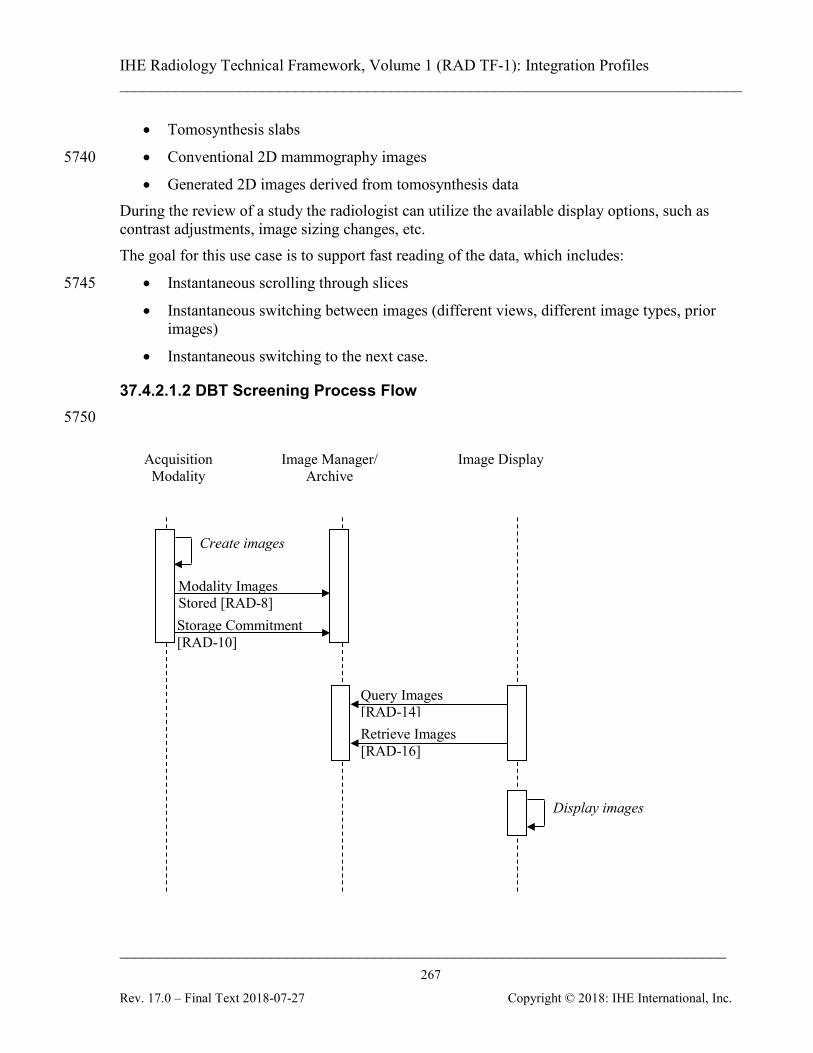
IHE Radiology Technical Framework, Volume 1 (RAD TF-1): Integration Profiles ______________________________________________________________________________
____________________________________________________________________________ 267
Rev. 17.0 – Final Text 2018-07-27 Copyright © 2018: IHE International, Inc.
• Tomosynthesis slabs
• Conventional 2D mammography images 5740
• Generated 2D images derived from tomosynthesis data During the review of a study the radiologist can utilize the available display options, such as contrast adjustments, image sizing changes, etc. The goal for this use case is to support fast reading of the data, which includes:
• Instantaneous scrolling through slices 5745
• Instantaneous switching between images (different views, different image types, prior images)
• Instantaneous switching to the next case.
37.4.2.1.2 DBT Screening Process Flow 5750
Query Images [RAD-14] Retrieve Images [RAD-16]
Storage Commitment [RAD-10]
Acquisition Modality
Image Manager/ Archive
Modality Images Stored [RAD-8]
Create images
Image Display
Display images
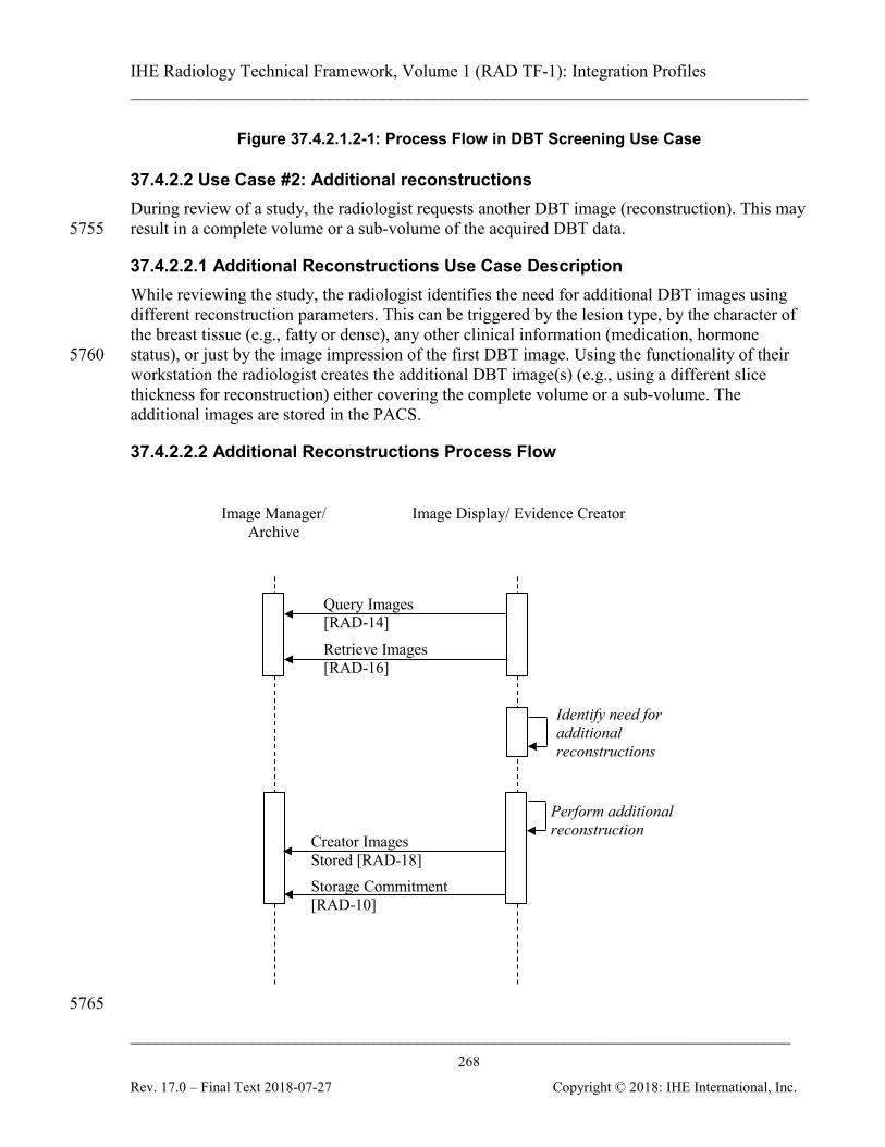
IHE Radiology Technical Framework, Volume 1 (RAD TF-1): Integration Profiles ______________________________________________________________________________
____________________________________________________________________________ 268
Rev. 17.0 – Final Text 2018-07-27 Copyright © 2018: IHE International, Inc.
Figure 37.4.2.1.2-1: Process Flow in DBT Screening Use Case
37.4.2.2 Use Case #2: Additional reconstructions During review of a study, the radiologist requests another DBT image (reconstruction). This may result in a complete volume or a sub-volume of the acquired DBT data. 5755
37.4.2.2.1 Additional Reconstructions Use Case Description While reviewing the study, the radiologist identifies the need for additional DBT images using different reconstruction parameters. This can be triggered by the lesion type, by the character of the breast tissue (e.g., fatty or dense), any other clinical information (medication, hormone status), or just by the image impression of the first DBT image. Using the functionality of their 5760 workstation the radiologist creates the additional DBT image(s) (e.g., using a different slice thickness for reconstruction) either covering the complete volume or a sub-volume. The additional images are stored in the PACS.
37.4.2.2.2 Additional Reconstructions Process Flow
5765
Query Images [RAD-14]
Retrieve Images [RAD-16]
Image Manager/ Archive
Image Display/ Evidence Creator
Perform additional reconstruction
Creator Images Stored [RAD-18] Storage Commitment [RAD-10]
Identify need for additional reconstructions
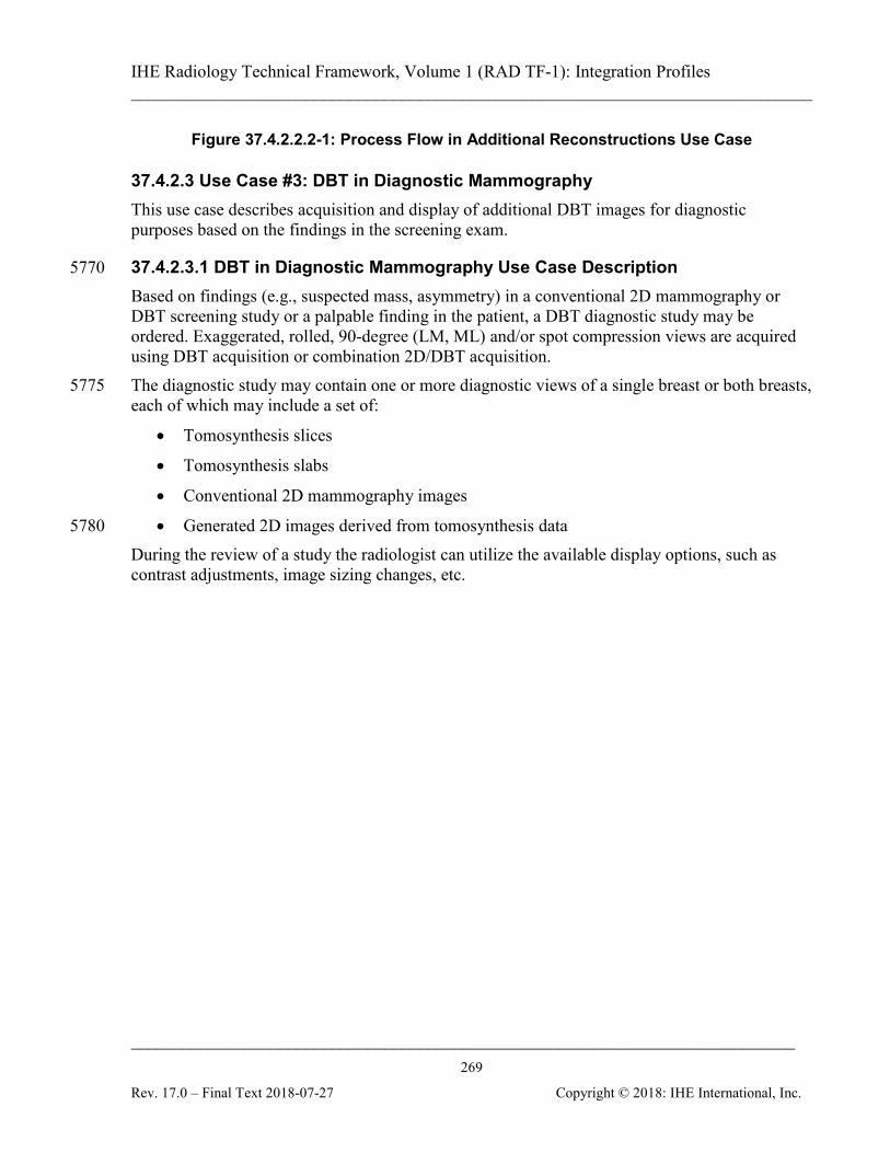
IHE Radiology Technical Framework, Volume 1 (RAD TF-1): Integration Profiles ______________________________________________________________________________
____________________________________________________________________________ 269
Rev. 17.0 – Final Text 2018-07-27 Copyright © 2018: IHE International, Inc.
Figure 37.4.2.2.2-1: Process Flow in Additional Reconstructions Use Case
37.4.2.3 Use Case #3: DBT in Diagnostic Mammography This use case describes acquisition and display of additional DBT images for diagnostic purposes based on the findings in the screening exam.
37.4.2.3.1 DBT in Diagnostic Mammography Use Case Description 5770 Based on findings (e.g., suspected mass, asymmetry) in a conventional 2D mammography or DBT screening study or a palpable finding in the patient, a DBT diagnostic study may be ordered. Exaggerated, rolled, 90-degree (LM, ML) and/or spot compression views are acquired using DBT acquisition or combination 2D/DBT acquisition. The diagnostic study may contain one or more diagnostic views of a single breast or both breasts, 5775 each of which may include a set of:
• Tomosynthesis slices
• Tomosynthesis slabs
• Conventional 2D mammography images
• Generated 2D images derived from tomosynthesis data 5780 During the review of a study the radiologist can utilize the available display options, such as contrast adjustments, image sizing changes, etc.
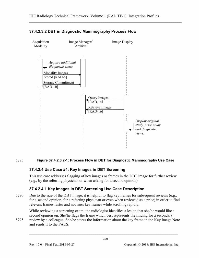
IHE Radiology Technical Framework, Volume 1 (RAD TF-1): Integration Profiles ______________________________________________________________________________
____________________________________________________________________________ 270
Rev. 17.0 – Final Text 2018-07-27 Copyright © 2018: IHE International, Inc.
37.4.2.3.2 DBT in Diagnostic Mammography Process Flow
Figure 37.4.2.3.2-1: Process Flow in DBT for Diagnostic Mammography Use Case 5785
37.4.2.4 Use Case #4: Key Images in DBT Screening This use case addresses flagging of key images or frames in the DBT image for further review (e.g., by the referring physician or when asking for a second opinion).
37.4.2.4.1 Key Images in DBT Screening Use Case Description Due to the size of the DBT image, it is helpful to flag key frames for subsequent reviews (e.g., 5790 for a second opinion, for a referring physician or even when reviewed as a prior) in order to find relevant frames faster and not miss key frames while scrolling rapidly. While reviewing a screening exam, the radiologist identifies a lesion that she/he would like a second opinion on. She/he flags the frame which best represents the finding for a secondary review by a colleague. She/he stores the information about the key frame in the Key Image Note 5795 and sends it to the PACS.
Query Images [RAD-14] Retrieve Images [RAD-16]
Storage Commitment [RAD-10]
Acquisition Modality
Image Manager/ Archive
Modality Images Stored [RAD-8]
Acquire additional diagnostic views
Image Display
Display original study, prior study and diagnostic views.
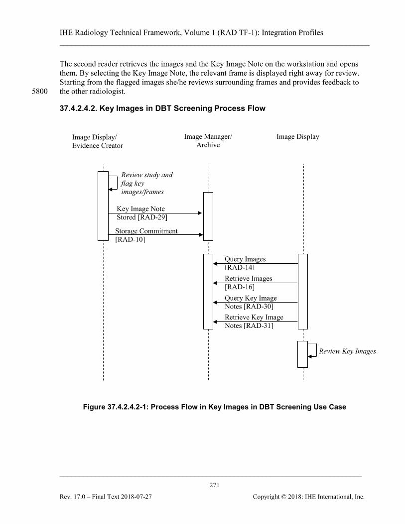
IHE Radiology Technical Framework, Volume 1 (RAD TF-1): Integration Profiles ______________________________________________________________________________
____________________________________________________________________________ 271
Rev. 17.0 – Final Text 2018-07-27 Copyright © 2018: IHE International, Inc.
The second reader retrieves the images and the Key Image Note on the workstation and opens them. By selecting the Key Image Note, the relevant frame is displayed right away for review. Starting from the flagged images she/he reviews surrounding frames and provides feedback to the other radiologist. 5800
37.4.2.4.2. Key Images in DBT Screening Process Flow
Figure 37.4.2.4.2-1: Process Flow in Key Images in DBT Screening Use Case
Key Image Note Stored [RAD-29]
Image Manager/ Archive
Image Display
Review Key Images
Image Display/ Evidence Creator
Review study and flag key images/frames
Retrieve Key Image Notes [RAD-31]
Query Key Image Notes [RAD-30]
Query Images [RAD-14] Retrieve Images [RAD-16]
Storage Commitment [RAD-10]
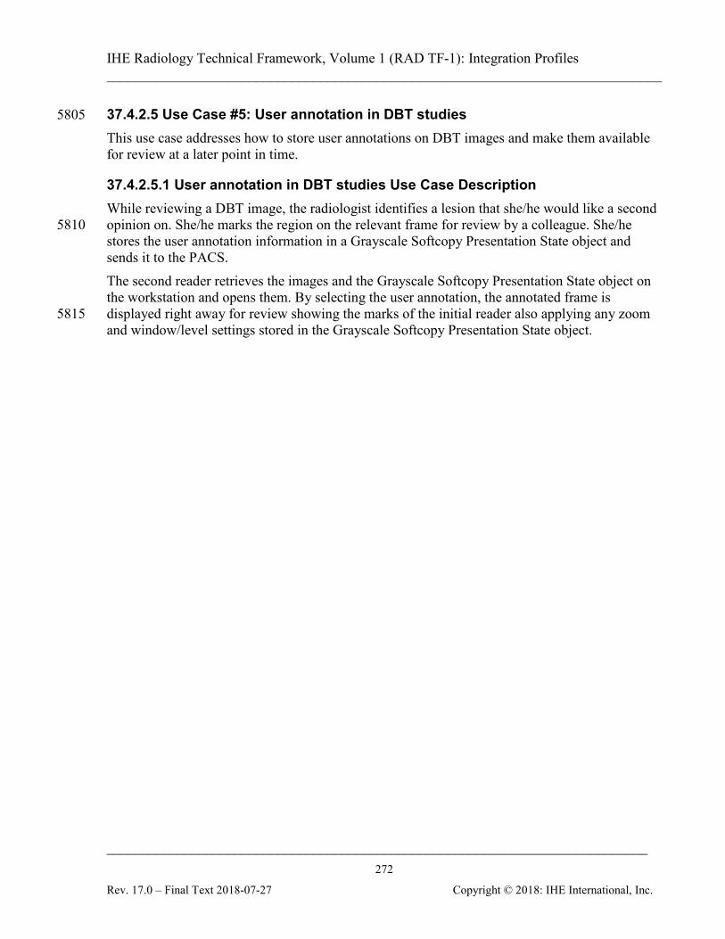
IHE Radiology Technical Framework, Volume 1 (RAD TF-1): Integration Profiles ______________________________________________________________________________
____________________________________________________________________________ 272
Rev. 17.0 – Final Text 2018-07-27 Copyright © 2018: IHE International, Inc.
37.4.2.5 Use Case #5: User annotation in DBT studies 5805 This use case addresses how to store user annotations on DBT images and make them available for review at a later point in time.
37.4.2.5.1 User annotation in DBT studies Use Case Description While reviewing a DBT image, the radiologist identifies a lesion that she/he would like a second opinion on. She/he marks the region on the relevant frame for review by a colleague. She/he 5810 stores the user annotation information in a Grayscale Softcopy Presentation State object and sends it to the PACS. The second reader retrieves the images and the Grayscale Softcopy Presentation State object on the workstation and opens them. By selecting the user annotation, the annotated frame is displayed right away for review showing the marks of the initial reader also applying any zoom 5815 and window/level settings stored in the Grayscale Softcopy Presentation State object.
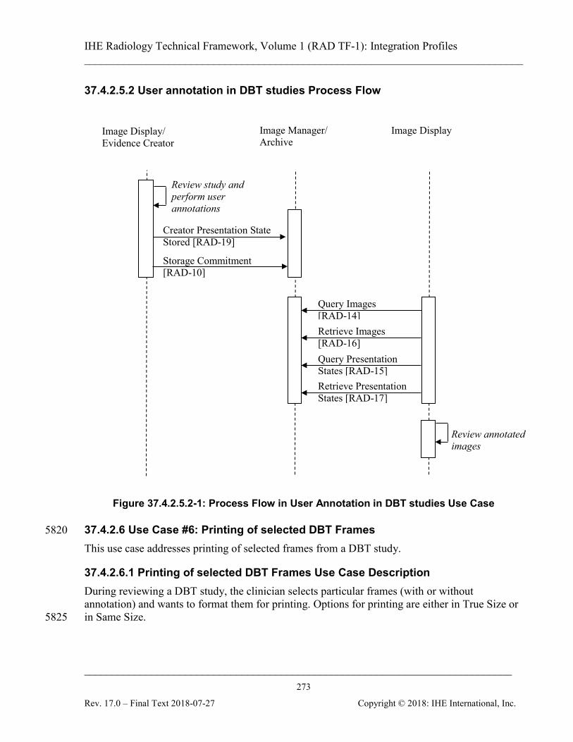
IHE Radiology Technical Framework, Volume 1 (RAD TF-1): Integration Profiles ______________________________________________________________________________
____________________________________________________________________________ 273
Rev. 17.0 – Final Text 2018-07-27 Copyright © 2018: IHE International, Inc.
37.4.2.5.2 User annotation in DBT studies Process Flow
Figure 37.4.2.5.2-1: Process Flow in User Annotation in DBT studies Use Case
37.4.2.6 Use Case #6: Printing of selected DBT Frames 5820 This use case addresses printing of selected frames from a DBT study.
37.4.2.6.1 Printing of selected DBT Frames Use Case Description During reviewing a DBT study, the clinician selects particular frames (with or without annotation) and wants to format them for printing. Options for printing are either in True Size or in Same Size. 5825
Creator Presentation State Stored [RAD-19]
Image Manager/ Archive
Image Display
Review annotated images
Image Display/ Evidence Creator
Review study and perform user annotations
Retrieve Presentation States [RAD-17]
Query Presentation States [RAD-15]
Query Images [RAD-14] Retrieve Images [RAD-16]
Storage Commitment [RAD-10]
IHE Radiology Technical Framework, Volume 1 (RAD TF-1): Integration Profiles ______________________________________________________________________________
____________________________________________________________________________ 274
Rev. 17.0 – Final Text 2018-07-27 Copyright © 2018: IHE International, Inc.
37.4.2.6.2 Printing of selected DBT Frames Process Flow
Figure 37.4.2.6.2-1: Process Flow in Printing of Selected DBT Frames Use Case
37.5 DBT Security Considerations N/A 5830
37.6 DBT Cross Profile Considerations SWF – Scheduled Workflow The main focus of the Digital Breast Tomosynthesis Profile is to define creation and review of digital breast tomosynthesis studies including DBT images and conventional 2D mammography images. The scheduling workflow is addressed in the Scheduled Workflow Profile. 5835 MAWF - Mammography Acquisition Workflow The main focus of the Digital Breast Tomosynthesis Profile is to define creation and review of digital breast tomosynthesis studies including DBT images and conventional 2D mammography images. The workflows addressing exception handling scenarios, e.g., converting a screening procedure into a diagnostic procedure, are defined in the Mammography Acquisition Workflow 5840
Print Request with Presentation LUT [RAD-23]
Image Manager/ Archive
Image Display / Print Composer
Review DBT images and select frames for printing
Query Images [RAD-14]
Retrieve Images [RAD-16]
Print Server
IHE Radiology Technical Framework, Volume 1 (RAD TF-1): Integration Profiles ______________________________________________________________________________
____________________________________________________________________________ 275
Rev. 17.0 – Final Text 2018-07-27 Copyright © 2018: IHE International, Inc.
Profile. The workflows defined in that profile are independent of the type of images acquired and therefore apply to studies including DBT images as well. BIR - Basic Image Review The Basic Image Review Profile clearly states that specialty viewing (like Mammography) is outside the scope of that profile. Therefore review of DBT images in the BIR Profile is confined 5845 to partial (display – only) support. Specific viewer requirements are addressed in Section 37.2.6.
38 Web-based Image Capture (WIC) This section intentionally, temporarily left blank.
39 Clinical Decision Support – Order Accountable Tracking (CDS-OAT) 5850
This section intentionally, temporarily left blank.
40 Radiation Exposure Monitoring – Nuclear Medicine (REM-NM) This section intentionally, temporarily left blank.
41 Cross-Enterprise Remove Reading Workflow Definition - (XRR-WD) This section intentionally, temporarily left blank. 5855
42 Intentionally Left Blank This section intentionally, temporarily left blank.
43 Standardized Operational Log Events (SOLE) This section intentionally, temporarily left blank.
44 Management of Acquisition Protocols (MAP) 5860
This section intentionally, temporarily left blank.
45 Results Distribution (RD) This section intentionally, temporarily left blank.
46 Intentionally Left Blank This section is intentionally left blank. 5865
47 Encounter-based Imaging Workflow (EBWI) This section intentionally, temporarily left blank.

IHE Radiology Technical Framework, Volume 1 (RAD TF-1): Integration Profiles ______________________________________________________________________________
____________________________________________________________________________ 276
Rev. 17.0 – Final Text 2018-07-27 Copyright © 2018: IHE International, Inc.
5870
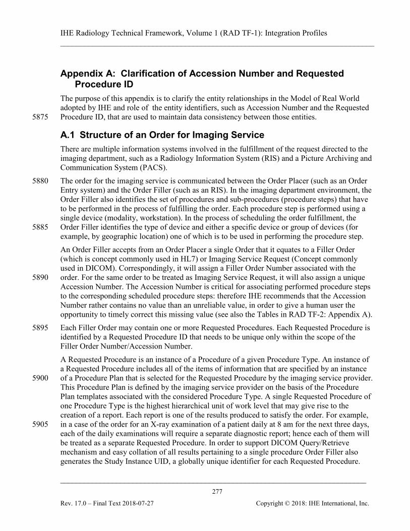
IHE Radiology Technical Framework, Volume 1 (RAD TF-1): Integration Profiles ______________________________________________________________________________
____________________________________________________________________________ 277
Rev. 17.0 – Final Text 2018-07-27 Copyright © 2018: IHE International, Inc.
Appendix A: Clarification of Accession Number and Requested Procedure ID
The purpose of this appendix is to clarify the entity relationships in the Model of Real World adopted by IHE and role of the entity identifiers, such as Accession Number and the Requested Procedure ID, that are used to maintain data consistency between those entities. 5875
A.1 Structure of an Order for Imaging Service There are multiple information systems involved in the fulfillment of the request directed to the imaging department, such as a Radiology Information System (RIS) and a Picture Archiving and Communication System (PACS). The order for the imaging service is communicated between the Order Placer (such as an Order 5880 Entry system) and the Order Filler (such as an RIS). In the imaging department environment, the Order Filler also identifies the set of procedures and sub-procedures (procedure steps) that have to be performed in the process of fulfilling the order. Each procedure step is performed using a single device (modality, workstation). In the process of scheduling the order fulfillment, the Order Filler identifies the type of device and either a specific device or group of devices (for 5885 example, by geographic location) one of which is to be used in performing the procedure step. An Order Filler accepts from an Order Placer a single Order that it equates to a Filler Order (which is concept commonly used in HL7) or Imaging Service Request (Concept commonly used in DICOM). Correspondingly, it will assign a Filler Order Number associated with the order. For the same order to be treated as Imaging Service Request, it will also assign a unique 5890 Accession Number. The Accession Number is critical for associating performed procedure steps to the corresponding scheduled procedure steps: therefore IHE recommends that the Accession Number rather contains no value than an unreliable value, in order to give a human user the opportunity to timely correct this missing value (see also the Tables in RAD TF-2: Appendix A). Each Filler Order may contain one or more Requested Procedures. Each Requested Procedure is 5895 identified by a Requested Procedure ID that needs to be unique only within the scope of the Filler Order Number/Accession Number. A Requested Procedure is an instance of a Procedure of a given Procedure Type. An instance of a Requested Procedure includes all of the items of information that are specified by an instance of a Procedure Plan that is selected for the Requested Procedure by the imaging service provider. 5900 This Procedure Plan is defined by the imaging service provider on the basis of the Procedure Plan templates associated with the considered Procedure Type. A single Requested Procedure of one Procedure Type is the highest hierarchical unit of work level that may give rise to the creation of a report. Each report is one of the results produced to satisfy the order. For example, in a case of the order for an X-ray examination of a patient daily at 8 am for the next three days, 5905 each of the daily examinations will require a separate diagnostic report; hence each of them will be treated as a separate Requested Procedure. In order to support DICOM Query/Retrieve mechanism and easy collation of all results pertaining to a single procedure Order Filler also generates the Study Instance UID, a globally unique identifier for each Requested Procedure.
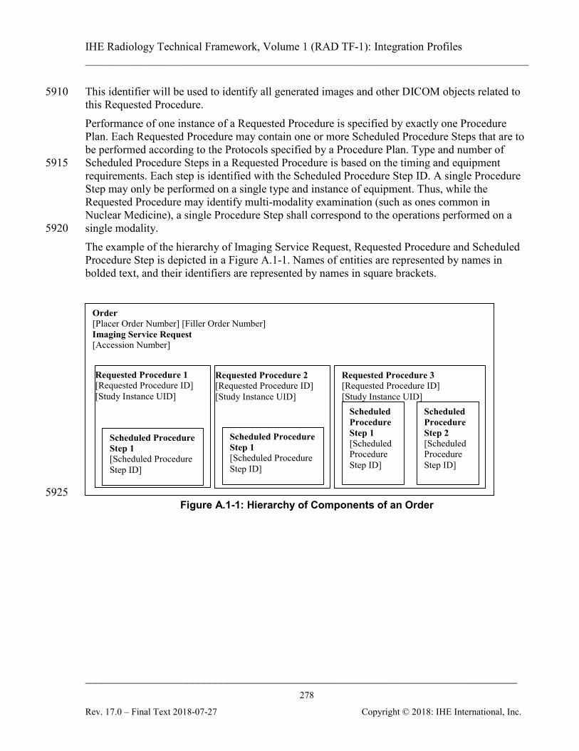
IHE Radiology Technical Framework, Volume 1 (RAD TF-1): Integration Profiles ______________________________________________________________________________
____________________________________________________________________________ 278
Rev. 17.0 – Final Text 2018-07-27 Copyright © 2018: IHE International, Inc.
This identifier will be used to identify all generated images and other DICOM objects related to 5910 this Requested Procedure. Performance of one instance of a Requested Procedure is specified by exactly one Procedure Plan. Each Requested Procedure may contain one or more Scheduled Procedure Steps that are to be performed according to the Protocols specified by a Procedure Plan. Type and number of Scheduled Procedure Steps in a Requested Procedure is based on the timing and equipment 5915 requirements. Each step is identified with the Scheduled Procedure Step ID. A single Procedure Step may only be performed on a single type and instance of equipment. Thus, while the Requested Procedure may identify multi-modality examination (such as ones common in Nuclear Medicine), a single Procedure Step shall correspond to the operations performed on a single modality. 5920 The example of the hierarchy of Imaging Service Request, Requested Procedure and Scheduled Procedure Step is depicted in a Figure A.1-1. Names of entities are represented by names in bolded text, and their identifiers are represented by names in square brackets. Order
[Placer Order Number] [Filler Order Number] Imaging Service Request [Accession Number]
Requested Procedure 2 [Requested Procedure ID] [Study Instance UID]
Requested Procedure 3 [Requested Procedure ID] [Study Instance UID]
Scheduled Procedure Step 1 [Scheduled Procedure Step ID]
Scheduled Procedure Step 1 [Scheduled Procedure Step ID]
Scheduled Procedure Step 2 [Scheduled Procedure Step ID]
Requested Procedure 1 [Requested Procedure ID] [Study Instance UID]
Scheduled Procedure Step 1 [Scheduled Procedure Step ID]
5925 Figure A.1-1: Hierarchy of Components of an Order
IHE Radiology Technical Framework, Volume 1 (RAD TF-1): Integration Profiles ______________________________________________________________________________
____________________________________________________________________________ 279
Rev. 17.0 – Final Text 2018-07-27 Copyright © 2018: IHE International, Inc.
Appendix B: Topics for Standards Corrections or Supplements
B.1 HL7 Topics
B.1.1 Version 2.5 5930 The IHE Radiology Technical Framework is primarily based on the version 2.3.1 of the HL7 standard (see RAD TF-2: 2.4.4 for discussion of HL7 Versioning). The definitions provided in the Technical Framework will specify the base version of HL7 used. For example, the Appointment Notification [RAD-48] transaction uses the SIU^S12 message first defined in HL7 Version 2.4 in order to take advantage of the additional scheduling information not available in 5935 previous versions. Likewise, IHE has had to provide temporary solutions in custom segments where definitions have not existed. An example is the definition of the [RAD-4] and [RAD-13] transactions which include a ZDS Segment as a temporary solution for handling Study Instance UID. A definition for the Study Instance UID did not exist until HL7 version 2.5 when definitions were added to 5940 the OMI (Imaging Order) message.
B.1.2 HL7 Conformance HL7 in its version 2.5 defines the concepts of HL7 conformance and HL7 profiles that provide standardized mechanism for HL7 specifications. IHE intends to document its definitions of HL7-based transactions using such mechanism. Note that HL7 conformance profiles are not related to 5945 IHE Integration Profiles and will be used only for purpose of better documentation of IHE requirements
B.2 DICOM Topics Implementers are expected to keep up with CP's in DICOM as well as in IHE. DICOM CPs may be found here: http://www.dclunie.com/dicom-status/status.html 5950
IHE Radiology Technical Framework, Volume 1 (RAD TF-1): Integration Profiles ______________________________________________________________________________
____________________________________________________________________________ 280
Rev. 17.0 – Final Text 2018-07-27 Copyright © 2018: IHE International, Inc.
Appendix C: Overview of the Information Exchange between Department System Scheduler/Order Filler and Image Manager
Information exchange between the Department System Scheduler/Order Filler and the Image Manager is performed on the intra-departmental level. Each actor manages a distinct domain of 5955 information within a department: patient, order and procedure performance information for the Department System Scheduler/Order Filler; image acquisition, storage and interpretation for the Image Manager. Each system, however, requires valid and current information from both domains.
C.1 Exchange of Patient Information 5960
The Department System Scheduler/Order Filler is a source of patient information for the Image Manager within the context of a department. The Image Manager does not receive information for a particular patient until the first order for a patient has been submitted to the department and corresponding procedures have been scheduled. At this point, the Department System Scheduler/Order Filler will communicate patient information to the Image Manager within 5965 [RAD-4] Procedure Scheduled. Subsequent updates of patient information are communicated by the Department System Scheduler/Order Filler to the Image Manager via the [RAD-12] Patient Update transaction. These changes will be reflected on the Image Manager and in the images, Grayscale Softcopy Presentation State and Key Image Note objects retrieved from the Image Archive. The Image 5970 Manager shall not initiate patient information changes.
C.2 Exchange of Visit and Order Information The Department System Scheduler/Order Filler is a source of visit and order information for the Image Manager. The Image Manager does not receive information for a particular patient’s visit until the first order for a patient originated within such a visit has been submitted to the 5975 department and corresponding procedures have been scheduled. At this point, the Department System Scheduler/Order Filler will communicate visit and order information to the Image Manager within Procedure Scheduled [RAD-4] Subsequent updates of visit information are communicated by the Department System Scheduler/Order Filler to the Image Manager via Patient Update [RAD-12]. These changes will 5980 be reflected on the Image Manager and in the images, Grayscale Softcopy Presentation State and Key Image Note objects retrieved from the Image Archive. The Image Manager shall not initiate visit information changes. Because the Radiology Technical Framework requires that the order information change will be performed through cancellation of the order in question and re-order, updates of order 5985 information are communicated by the Department System Scheduler/Order Filler to the Image Manager via a sequence of two transactions – Procedure Update [RAD-13] (conveying order cancel) and Procedure Scheduled [RAD-4] (conveying new order information). The Image Manager shall not initiate order information changes.
IHE Radiology Technical Framework, Volume 1 (RAD TF-1): Integration Profiles ______________________________________________________________________________
____________________________________________________________________________ 281
Rev. 17.0 – Final Text 2018-07-27 Copyright © 2018: IHE International, Inc.
C.3 Exchange of Procedure Information 5990
The Department System Scheduler/Order Filler is a source of Requested Procedure information for the Image Manager. The Image Manager does not receive information for a particular procedure until it has been scheduled. At this point, the Department System Scheduler/Order Filler will communicate visit and order information to the Image Manager within Procedure Scheduled [RAD-4]. 5995 Subsequent updates of procedure information (re-scheduling, change of procedure code, etc.) are communicated by the DSS/Order Filler to the Image Manager via Procedure Update [RAD-13]. The Image Manager shall not initiate Requested Procedure information changes. In the Scheduled Workflow Group Case (RAD TF-2: 4.6.4.1.2.3.4) and Import Reconciliation Workflow Scheduled Import (RAD TF-2: Table A.5-1), certain imaging information submitted 6000 to the Image Manager from the Acquisition Modality or the Importer will differ from that provided by the Department System Scheduler/Order Filler. This information can include the Study Instance UID and the Performed Procedure, Performed Procedure Step and Performed Protocol. For these defined cases this imaging information shall not be subject to change by either the Department System Scheduler/Order Filler or the Image Manager. 6005 The behavior for handling the case where the imaging information differs because the Acquisition Modality does not conform to Scheduled Workflow is not defined.
IHE Radiology Technical Framework, Volume 1 (RAD TF-1): Integration Profiles ______________________________________________________________________________
____________________________________________________________________________ 282
Rev. 17.0 – Final Text 2018-07-27 Copyright © 2018: IHE International, Inc.
Appendix D: IHE Integration Statements IHE Integration Statements are documents prepared and published by vendors to describe the 6010 intended conformance of their products with the IHE Technical Framework. They identify the specific IHE capabilities a given product is designed to support in terms of the key concepts of IHE: Actors and Integration Profiles (described in Section 2). Users familiar with these concepts can use Integration Statements as an aid to determine what level of integration a vendor asserts a product supports with complementary systems and what 6015 clinical and operational benefits such integration might provide. Integration Statements are intended to be used in conjunction with statements of conformance to specific standards (e.g., HL7, DICOM, W3C, etc.). IHE provides a process for vendors to test their implementation of IHE actors and integration profiles. The IHE testing process, culminating in a multi-party interactive testing event called the 6020 Connect-a-thon, provides vendors with valuable feedback and provides a baseline indication of the conformance of their implementations. The process is not, however, intended to independently evaluate, or ensure, product compliance. In publishing the results of the Connect-a-thon, and facilitating access to vendors’ IHE Integration Statements, IHE and its sponsoring organizations are in no way attesting to the accuracy or validity of any vendor’s IHE Integration 6025 Statements or any other claims by vendors regarding their products. IMPORTANT -- PLEASE NOTE: Vendors have sole responsibility for the accuracy and validity of their IHE Integration Statements. Vendors’ Integration Statements are made available through IHE simply for consideration by parties seeking information about the integration capabilities of particular products. IHE and its sponsoring organizations have not evaluated or 6030 approved any IHE Integration Statement or any related product, and IHE and its sponsoring organizations shall have no liability or responsibility to any party for any claims or damages, whether direct, indirect, incidental or consequential, including but not limited to business interruption and loss of revenue, arising from any use of, or reliance upon, any IHE Integration Statement. 6035
D.1 Structure and Content of an IHE Integration Statement An IHE Integration Statement for a product shall include:
1. The Vendor Name 2. The Product Name (as used in the commercial context) to which the IHE Integration
Statement applies. 6040 3. The Product Version to which the IHE Integration Statement applies. 4. A publication date. 5. The following statement:
“This product is intended to implement all transactions required in the IHE Technical Framework to support the IHE Integration Profiles, Actors and Options listed below:” 6045
IHE Radiology Technical Framework, Volume 1 (RAD TF-1): Integration Profiles ______________________________________________________________________________
____________________________________________________________________________ 283
Rev. 17.0 – Final Text 2018-07-27 Copyright © 2018: IHE International, Inc.
6. A list of IHE Integration Profiles supported by the product and, for each integration profile, a list of IHE actors supported. For each integration profile/actor combination one or more of the options defined in the IHE Technical Framework may also be stated. Profiles, Actors and Options shall use the names defined by the IHE Technical Framework Volume 1. 6050
Note: The vendor may also elect to indicate the version number of the Technical Framework referenced for each integration profile.
Note that implementation of the integration profile presumes implementation of all required transactions for an actor; options include optional transactions or optional functions for required transactions. 6055 The statement shall also include references and/or internet links to the following information:
1. The specific internet address (or universal resource locator [URL]) where the vendor’s Integration Statements are posted
2. The specific URL where the vendor’s standards conformance statements (e.g., HL7, DICOM, etc.) relevant to the IHE transactions implemented by the product are posted. 6060
3. The URL of the IHE Initiative’s web page for general information on IHE (www.rsna.org/IHE).
An IHE Integration Statement is not intended to promote or advertise aspects of a product not directly related to its implementation of IHE capabilities.
D.2 Format of an IHE Integration Statement 6065
Each Integration Statement shall follow the format shown below. Vendors may add a cover page and any necessary additional information in accordance with their product documentation policies. 6070 6075 6080
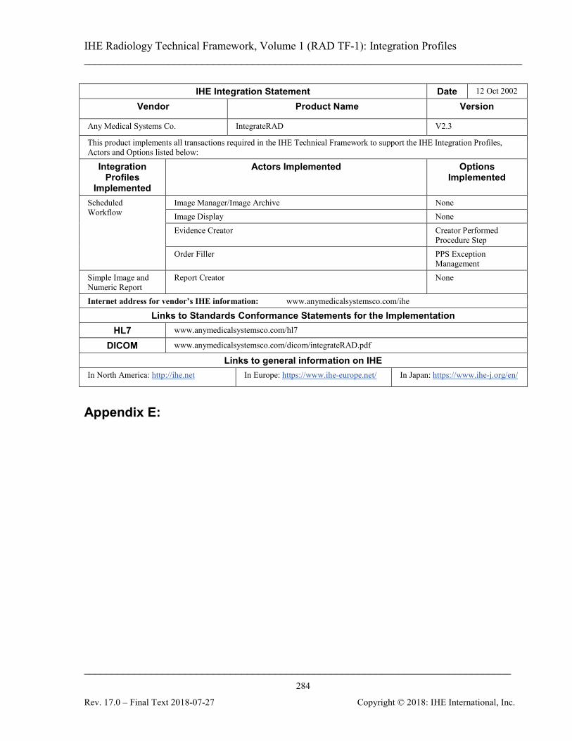
IHE Radiology Technical Framework, Volume 1 (RAD TF-1): Integration Profiles ______________________________________________________________________________
____________________________________________________________________________ 284
Rev. 17.0 – Final Text 2018-07-27 Copyright © 2018: IHE International, Inc.
IHE Integration Statement Date 12 Oct 2002
Vendor Product Name Version
Any Medical Systems Co. IntegrateRAD V2.3
This product implements all transactions required in the IHE Technical Framework to support the IHE Integration Profiles, Actors and Options listed below:
Integration Profiles
Implemented
Actors Implemented Options Implemented
Scheduled Workflow
Image Manager/Image Archive None Image Display None Evidence Creator Creator Performed
Procedure Step Order Filler PPS Exception
Management Simple Image and Numeric Report
Report Creator None
Internet address for vendor’s IHE information: www.anymedicalsystemsco.com/ihe
Links to Standards Conformance Statements for the Implementation HL7 www.anymedicalsystemsco.com/hl7
DICOM www.anymedicalsystemsco.com/dicom/integrateRAD.pdf
Links to general information on IHE In North America: http://ihe.net In Europe: https://www.ihe-europe.net/ In Japan: https://www.ihe-j.org/en/
Appendix E:
IHE Radiology Technical Framework, Volume 1 (RAD TF-1): Integration Profiles ______________________________________________________________________________
____________________________________________________________________________ 285
Rev. 17.0 – Final Text 2018-07-27 Copyright © 2018: IHE International, Inc.
Appendix E: Nuclear Medicine Note that the NM Image Profile is undergoing revision, and vendors considering implementation are advised to include the modifications contained in the trial implementation version “NM 6085 Image Profile with Cardiac Option”. For additional information please contact the IHE Radiology Technical Committee at [email protected].
E.1 Introduction This Appendix provides a description of relevant aspects of Nuclear Medicine in the context of the IHE Radiology Technical Framework. This includes descriptions of some typical Nuclear 6090 Medicine workflows and how they can be supported within the framework of the current Scheduled Workflow and Post-Processing Workflow Integration Profiles. Characteristics of typical NM Images are presented and examples of typical displays of NM Images are provided. This Appendix is informative, not normative. The mapping of workflows to the IHE Model, and other details of NM practice are sufficiently complex and/or misunderstood that this Appendix 6095 has been included to clarify such issues and provide examples of some sensible approaches. The examples and details here are not intended to be exhaustive. The mappings to the workflow model of IHE shown here are valid but do not represent the only valid mappings.
E.2 NM Workflow Overview First it should be said that the normal scheduled workflow of: 6100
• registering a patient
• placing an order
• scheduling an acquisition
• retrieving a worklist at the modality
• performing an acquisition 6105
• generating images
• storing images to the archive
• retrieving images for review
• generating a report … is certainly applicable to NM studies. 6110 That being said, it is perhaps most instructive to proceed to describe the ways in which NM workflow can differ from typical radiology workflow and what assumptions may not be valid or may require special consideration for NM.
IHE Radiology Technical Framework, Volume 1 (RAD TF-1): Integration Profiles ______________________________________________________________________________
____________________________________________________________________________ 286
Rev. 17.0 – Final Text 2018-07-27 Copyright © 2018: IHE International, Inc.
E.2.1 Injection Steps All nuclear medicine studies depend on the injection of radio-pharmaceutical tracers (although a 6115 given series may be imaging a radio-pharmaceutical injected hours or days earlier). Note that although this document refers to injection of the radio-pharmaceutical, it may also be given orally or by some other route. The required dose of radio-pharmaceutical must be ordered from the pharmacy and delivery arranged to coincide with the scheduled patient procedure. Other aspects include updates for 6120 changed or cancelled orders, tracking the radioactive materials, performing QA and confirming the count levels of the delivered dose, etc. The injection procedure step itself is also generally scheduled and its execution logged and tracked both because time from injection factors in to most protocols and because the drug administration should go into the patient record. 6125 As will be discussed in the following section on NM Worklist Guidelines, most of these tasks would fall in the scope of yet-to-be-developed profiles relating to Pharmacy and Enterprise Scheduling but the injection step may fall in the scope of Scheduled Workflow.
E.2.2 Time Separated Acquisitions Standard NM clinical practice includes protocols which require the patient to leave the 6130 acquisition equipment between acquisition steps. Some imaging procedures include multiple acquisition steps separated by some time interval. This time interval can be anywhere from 1 or 2 hours, up to as much as a few days. This means that the patient leaves the imaging system in between parts of the procedure. When the patient returns, it is possible that the new acquisitions may be done on a different system based on 6135 availability. Therefore, there can be no assumption that the same acquisition system is involved in all steps of a given procedure. On the other hand, some protocols may involve several acquisition steps done at-once, back-to-back.
E.2.3 Reconstruction as a Separate Operation 6140 NM differs from other modalities in the relationship between acquisition and reconstruction processes. In most modalities the raw acquisition data has little clinical use. Reconstruction is generally performed on the modality and only the reconstructed images are exported from the modality. For NM studies, the raw projection images are clinically useful images, and are often exported 6145 and viewed using the NM IOD. When these projection images are tomographic (i.e., Image Type = TOMO or GATED TOMO) they can also be reconstructed into volume images similar to CT or MR images, i.e., a stack of slices. Although this reconstruction process can be done on the acquisition system as is done in most modalities, due to the availability of exported tomographic images, it may also be done on 6150
IHE Radiology Technical Framework, Volume 1 (RAD TF-1): Integration Profiles ______________________________________________________________________________
____________________________________________________________________________ 287
Rev. 17.0 – Final Text 2018-07-27 Copyright © 2018: IHE International, Inc.
other workstations depending on site preferences for particular vendors reconstruction algorithms, processing loads, and other workflow issues.
E.2.4 Acquisition Post-Processing In addition to reconstruction, there are a number of other acquisition related processing steps performed on the acquired images. This includes: 6155
• Uniformity Correction - to correct for non-uniformities in the detector hardware
• Decay Correction - to correct for radioactive decay of the injected tracer over time
• Scatter Correction - to remove photons scattered by tissue rather than emitted by the tracer
• Attenuation Correction - to compensate for photons absorbed within the body 6160
• Patient Motion Correction - to compensate for patient motion during the scan
• Center of Rotation Correction - to compensate for offsets in the axis of rotation Other possible corrections include deadtime, energy and linearity. Some of these corrections, especially those that are hardware dependent or are specific to an acquisition system, must be performed on the acquisition modality if they are performed at all. 6165 To avoid encouraging potentially incomplete attempts to carry out these corrections away from the modality, the NM IOD intentionally leaves out attributes for attempting to convey all the relevant information. Other steps, although generally performed on the acquisition modality, may, like reconstruction, be performed on a separate workstation depending on system capabilities and site preferences. 6170
E.2.5 Clinical Post Processing Finally, due to the metabolic/qualitative nature of NM imaging, it is very common to perform clinical processing on the images to extract quantitative details prior to final review. These clinical processing packages too are sometimes available on the acquisition modality but may also be on a separate workstation. This processing includes things like: 6175
• Re-orientation of volumes
• 2D and/or 3D segmentation (automatic and/or manual)
• Calculation of region characteristics
• Generation of time-plots
• Computation of functional images 6180
• Generation of Result Screens These activities are sometimes performed immediately following acquisition or may be left for batch processing at a later time.
IHE Radiology Technical Framework, Volume 1 (RAD TF-1): Integration Profiles ______________________________________________________________________________
____________________________________________________________________________ 288
Rev. 17.0 – Final Text 2018-07-27 Copyright © 2018: IHE International, Inc.
E.2.6 Display and Reviewing Unlike other modalities where the raw acquisition data has little clinical use, for NM images, the 6185 raw projection images are clinically useful images, and are often reviewed by the reading radiologist together with processed results. Also, the color presentation of the images is common in Nuclear Medicine and is a clinical necessity for the interpretation of certain images.
E.2.7 Workflow Chaining 6190 Due to the common use of processing workstations and clinical processing before reporting, the work on chained workflows being discussed in the IHE Radiology Technical Committee whitepaper on Departmental Workflow will be of particular interest and relevance to Nuclear Medicine.
E.3 NM Worklists 6195
The following informative text provides guidance on how NM activities would most logically be mapped to IHE Worklists and the concepts of Scheduled and Performed Procedure Steps. The Scheduled Workflow Profile and Post-Processing Profile are very flexible in allowing complex procedures to be scheduled as a single procedure step (potentially with multiple procedure codes) or as multiple procedure steps. There are some situations which can work 6200 equally well with either approach, and ultimately sites will need to have some flexibility in how the work is scheduled in order to fit their work patterns. That being said, the following are some basic guidelines which represent a sensible approach that should be considered. After the guidelines are a number of examples of how the guidelines would be applied to cases taken from typical clinical practice. 6205
E.3.1 NM Worklist Guidelines
E.3.1.1 Injections Scheduling, preparing, tracking and delivering the required dose of radio-pharmaceutical tracer is the job of the pharmacy and it does not make particular sense to include it in the worklists currently managed by the Radiology Profiles. It would make sense to address this in future 6210 Pharmacy and Enterprise Scheduling Profiles which would also handle related issues, such as changing or canceling the order, managing drug interactions, QA and tracking of radioactive materials, etc. The injection procedure step itself may also be scheduled and is frequently performed in proximity to the imaging equipment and in the presence of, or by, the modality operator. 6215 As a practical matter, pending development of the above mentioned profiles, it would be useful and not unreasonable for the DSS/Order Filler and the Acquisition Modality to allow injection steps to be placed on the Modality Worklist, either as procedure codes in an acquisition procedure step or as an independent procedure step.

IHE Radiology Technical Framework, Volume 1 (RAD TF-1): Integration Profiles ______________________________________________________________________________
____________________________________________________________________________ 289
Rev. 17.0 – Final Text 2018-07-27 Copyright © 2018: IHE International, Inc.
Further, the modality could allow the operator to indicate that the injection has been completed 6220 and generate corresponding MPPS details. Supporting codes for injections is not a requirement, but would be a useful feature. Note that the NM Image IOD already has attributes in the NM Isotope Module for modality systems that track injection details. If the injection step is to be performed at the time of an acquisition, then it would be appropriate for the injection to be included as one Item in the Protocol Code Sequence within the Scheduled 6225 Procedure Step for the acquisition. Injections that are performed outside of the acquisition room, some time prior to the data acquisition, are not particularly appropriate for inclusion in a modality worklist and are out of scope of this discussion. While charges for radio-pharmaceuticals are generally built into the technical procedure fee, it 6230 would be appropriate and sometimes useful to include details about the radio-pharmaceutical dose in the Billing and Material Management Option described in RAD TF-2: 4.7. In cases where the MPPS indicates the procedure was cancelled, if an injection was still performed, it would be appropriate to include that information in the MPPS.
E.3.1.2 Acquisitions 6235 It is suggested that, in general, each acquisition of image data be scheduled as a separate procedure step. Clinical protocols that include having the patient leave the acquisition system between acquisition steps, must schedule them as separate Scheduled Procedure Steps. However, when several acquisition steps are done at-once, back-to-back, they can either be scheduled as multiple 6240 Scheduled Procedure Steps, or as a single Scheduled Procedure Step with multiple protocol codes. Scheduling using multiple Scheduled Procedure Steps allows the greatest flexibility in use of available equipment and the greatest detail in status reporting. Of course the acquisitions will still likely be part of the same Study with the same Study UID. Note that support of multiple Scheduled Procedure Steps resulting from a single Requested 6245 Procedure is already required in the Scheduled Workflow Profile, but support of multiple protocol codes is optional. Support for multiple performed protocol codes in the Performed Procedure Step is recommended. An issue worth mentioning is that due to studies involving multiple acquisitions, several acquisition modality systems may participate in the same study. While the Study Instance UID is 6250 obtained from the Worklist by both modalities and will be correctly included, the rest of the Study level information, such as study date/time, study description, etc., is generally not provided in the Worklist. This means that each modality will generate their own values and include them in the generated images, resulting in Series instances in the same Study which have different Study level information (except the UID). It is assumed that the Image 6255 Manager/Archive will manage any issues related to this.
IHE Radiology Technical Framework, Volume 1 (RAD TF-1): Integration Profiles ______________________________________________________________________________
____________________________________________________________________________ 290
Rev. 17.0 – Final Text 2018-07-27 Copyright © 2018: IHE International, Inc.
E.3.1.3 Reconstruction It is recommended that the reconstruction of acquired (tomographic) image data be treated as a separate Performed Procedure Step. That is, the acquisition system should issue a Performed Procedure Step Complete message when the tomographic acquisition is complete. 6260 Then, whatever system performs the reconstruction of this data, whether it is the original acquisition system, or some other system, should issue a new Performed Procedure Step for the reconstruction process, related to the same Scheduled Procedure Step. In this way, scheduling of tomographic acquisitions is consistent with other modalities like CT, but allows the reconstruction to be performed flexibly by any system. 6265 These Reconstruction steps, and other post-processing, may carried out as explicit workflow by placing them on worklists as outlined in the Post-Processing Workflow Profile, or may be carried out as implicit workflow by the operator knowing these steps should follow acquisition as outlined in the Scheduled Workflow Profile.
E.3.1.4 Acquisition Post-Processing 6270 Due to the nature of Acquisition Post-Processing, as described in Section E.2.4, it will almost always be performed on the acquisition system or on a workstation bundled with the acquisition system. While it is conceivable that some batch oriented site workflows could benefit from doing these steps with an explicit worklist, the vast majority of sites will do these steps as implicit workflow. Further, the acquisition post-processing steps are seldom billable and there is little 6275 need for detailed tracking of these steps. If the processing is performed on a separate workstation the steps should be considered as separate procedure steps but there is likely only a need to create Performed Procedure Step messages when the step creates new images which will be sent to the Image Manager/Archive. If the processing is performed on the acquisition modality system, which is the most likely, it is 6280 acceptable to include the steps as additional protocol codes.
E.3.1.5 Clinical Post-Processing Clinical Post-Processing, as described in Section E.2.5, may be done at some sites using explicit workflow, although many sites will handle it with implicit workflow. If the processing is performed on a separate workstation the steps should be handled as separate 6285 procedure steps, either scheduled as explicit workflow as described in the Post-Processing Workflow Profile or unscheduled as implicit workflow as described in the Scheduled Workflow Profile. If the processing is performed on the acquisition modality system it is acceptable to include the steps as additional protocol codes, however it is recommended to handle them as separate 6290 procedures steps.
IHE Radiology Technical Framework, Volume 1 (RAD TF-1): Integration Profiles ______________________________________________________________________________
____________________________________________________________________________ 291
Rev. 17.0 – Final Text 2018-07-27 Copyright © 2018: IHE International, Inc.
E.3.2 NM Worklist Examples The following are some examples of clinical situations and an example of an appropriate way to handle them based on the above guidelines.
E.3.2.1 Injection and immediate imaging 6295 Example: Renal scan (Dynamic) The patient is injected under the camera, and imaging is started immediately. Use a single SPS which includes protocol codes for the injection and for a single acquisition.
E.3.2.2 Injection and delayed imaging Example: Bone scan to assess for malignancy (Static or Whole body) 6300 The patient is injected somewhere (could be in the imaging department or at the patient bedside), and images are obtained several hours later. Use a single SPS which includes a single acquisition. The injection details are handled out of scope.
E.3.2.3 Injection with both immediate and delayed imaging 6305 Example: 3-phase bone scan for infection (Dynamic and Static) The patient is injected under the camera, and imaging is started immediately. More images are obtained several hours later, on the same or a different gamma camera. Use two SPS. The first SPS includes protocol codes for both the injection and the initial dynamic and static acquisitions. The second SPS is for the second static acquisition. Images acquired from 6310 the second SPS must be in a different Series from those from the first SPS.
E.3.2.4 Injection and immediate imaging, with possible further imaging Example: Renal scan to evaluate for obstruction, with possible second diuretic acquisition (Dynamic) The patient is injected under the camera, and imaging is started immediately. The results will 6315 determine whether more imaging is needed. Schedule two SPS as in E.3.2.3. The images from the first SPS can be read, and then a determination can be made as to whether or not the second acquisition is required. If it is not needed, then the second SPS can be cancelled at the modality by issuing an MPPS aborted message. 6320
E.3.2.5 Injection and very delayed imaging Example: I-131 whole body imaging (Whole body) The patient dose is given, and images obtained days later.
IHE Radiology Technical Framework, Volume 1 (RAD TF-1): Integration Profiles ______________________________________________________________________________
____________________________________________________________________________ 292
Rev. 17.0 – Final Text 2018-07-27 Copyright © 2018: IHE International, Inc.
Optionally schedule one SPS for the injection if it is performed in the imaging suite. An SPS would be scheduled for the acquisition. 6325
E.3.2.6 Imaging and no injection Example: Add-on imaging after therapeutic administration by radiation oncology (Static or Whole body) The patient dose is given by someone else in the radiation oncology department for the purpose of therapy. Several days later, imaging is performed for evaluation purposes. 6330 A single SPS is used for the image acquisition.
E.3.2.7 Two isotope examination, with two imaging times Example: Dual isotope [Thallium-201 “rest” images & Tc-99m Sestamibi “stress” images] myocardial perfusion study (Gated Tomo) The first isotope is injected followed by image acquisition. A second isotope (possibly under 6335 different patient conditions) is subsequently injected followed by a second image acquisition (possibly on a different camera). This protocol uses two SPS. The first contains protocol codes for the first injection and the first acquisition. The second SPS contains protocol codes for the second injection and acquisition. Each of these two acquisitions constitutes a separate Series. 6340 It should be noted that these are simply suggestions of one approach that makes sense. Sites will of course be interested in scheduling in ways that make sense to them. It is conceivable that an ECG or Treadmill might implement Modality Worklist, allowing their activities to be scheduled and monitored steps, however such actors do not currently exist in the framework and such implementations are currently unlikely. 6345
E.3.2.8 Two isotope examination, with single imaging time Example: Dual isotope [In-111 labeled White blood cell “infection” images & Tc-99 sulfur colloid “bone marrow” images] infection study (Dual Energy Static or Whole body) In this example the first isotope is injected on day one. Then the following day the second isotope is injected 30 minutes before the acquisition step which images both isotopes. 6350 Consider three SPS. The first SPS (optional) for the first injection, the second SPS for the second injection, and the third SPS for the actual acquisition. Note that this case might result in billing for two exams (White Blood Cell study and Bone Marrow imaging), but most centers would actually only issue a single report, since there was only one imaging step. This is sort of like the case where an abdomen and pelvis CT was done as 6355 a single acquisition, and then read by the same person, but billed as two "studies" (i.e., the PGP Profile).

IHE Radiology Technical Framework, Volume 1 (RAD TF-1): Integration Profiles ______________________________________________________________________________
____________________________________________________________________________ 293
Rev. 17.0 – Final Text 2018-07-27 Copyright © 2018: IHE International, Inc.
E.3.2.9 Acquisition and Reconstruction on the Acquisition Modality Example: Cardiac Tomographic acquisition followed by basic corrections, reconstruction and re-orientation to align the volume with the cardiac Short Axis. 6360 A single SPS is created which calls for one cardiac tomographic acquisition. The modality performs the acquisition and sends an MPPS Complete message, referencing the created tomographic images. The modality then does corrections and reconstruction of the tomographic data, appends a new MPPS and reports it complete, without referencing the intermediate image data. 6365 Finally, the reconstructed data is re-oriented into cardiac Short Axis images and the modality appends a third MPPS to report the reformatting processing, and referencing the re-oriented slices. The initial tomographic images and the final re-oriented slices are stored to the Image Manager/Archive. 6370 This example raises a sometimes overlooked point. MPPS transactions should only include references to series/images which will be (or have been) sent to the Image Manager/Archive. The implication of including the references is that they will be sent to the Image Manager/Archive. Correspondingly, the Image Manager/Archive will be waiting for all referenced images and may continue to consider the study incomplete until they arrive. Thus, referencing images which will 6375 not be sent can have the effect of derailing the workflow.
E.3.2.10 Re-orientation on an Evidence Creator with Implicit Workflow Example: Same as the previous case, but all of the processing takes place on a separate Evidence Creator based on implicit workflow as described in Scheduled Workflow. A single SPS is created which calls for one cardiac tomographic acquisition. The modality 6380 performs the acquisition and sends an MPPS Complete message. The modality then does corrections and reconstruction of the tomographic data, appends a new MPPS and reports it complete. The initial tomographic images are stored to the Image Manager/Archive and the reconstructed slices are stored to the Evidence Creator workstation. 6385 The workstation re-orients the reconstructed data into cardiac Short Axis images and sends a new MPPS to the PPS Manager. The SPS and patient references in the created images and MPPS are copied from the information in the received slice images. The Evidence Creator stores the final re-oriented slices to the Image Manager/Archive.
E.3.2.11 Re-orientation and Post-Processing on an Evidence Creator with 6390 Explicit Workflow Example: Same as the previous case, but the work is placed on a Post-Processing Worklist and the Evidence Creator also performs post-processing that produces some Result Screens.
IHE Radiology Technical Framework, Volume 1 (RAD TF-1): Integration Profiles ______________________________________________________________________________
____________________________________________________________________________ 294
Rev. 17.0 – Final Text 2018-07-27 Copyright © 2018: IHE International, Inc.
A single SPS is created on the Post-Processing Worklist with codes for Re-orientation and Clinical Result Processing. 6395 When the task is selected and the inputs are available on the Evidence Creator, the re-orientation is performed followed by Clinical Result Processing. The Evidence Creator sends an MPPS Complete for the two codes. The re-oriented slice images and result screens are stored to the Image Manager/Archive. The timing of placing the SPS on the Post-Processing Worklist is not discussed here as that is the 6400 topic of an IHE Radiology Technical Committee whitepaper on Departmental Workflow and is still under discussion. In the above two cases, data was considered to be pushed from the Acquisition Modality to the Evidence Creator. This is a typical practice, but it should be noted that the mechanism for this is not specified by IHE. The processing system may retrieve the images from the acquisition 6405 modality, the acquisition modality may push them to the processing system, or the Image Manager/Archive could be used as a common storage and retrieval point. Also, applications that perform clinical post-processing often need to identify specific related series to use as inputs for processing (for example the corresponding stress and rest series for a cardiac study). The software should look to the DICOM fields to determine the patient state and 6410 type of Image. The information in the fields may be utilized automatically by the software or may be presented to the user for manual selection.
E.4 NM Data The NM Image IOD (refer to DICOM PS 3.3 C.8.4) supports several NM Image Types as indicated by the code contained in Value 3 of the Image Type (0008,0008) attribute. 6415 The currently allowed Image Types are: STATIC - Simple projection image containing one or more frames (e.g., individual views of the lungs). WHOLE BODY - Projection image where each frame spans the length of the body (e.g., an anterior and/or posterior view of the body). 6420 DYNAMIC - Projection image containing a series of frames typically showing the same anatomy over time (e.g., a view of renal isotope uptake and washout). GATED - Similar to DYNAMIC, except the frames are composed to span phases of a gated interval (e.g., a beating view of the heart). TOMO - Projection image with frames take from various angles as the detector rotates about the 6425 patient. Generally used to reconstruct volume slices. RECON TOMO - Reconstructed image with frames corresponding to cross-sectional slices covering a volume. Created by reconstructing TOMO image frames. GATED TOMO - Similar to TOMO, except each angle has multiple frames representing the phases over a gated interval. Generally used to reconstruct gated volume slices. 6430

IHE Radiology Technical Framework, Volume 1 (RAD TF-1): Integration Profiles ______________________________________________________________________________
____________________________________________________________________________ 295
Rev. 17.0 – Final Text 2018-07-27 Copyright © 2018: IHE International, Inc.
RECON GATED TOMO - Reconstructed image with frames corresponding to cross-sectional slices covering a volume at each phase of a gated interval (e.g., a beating heart volume, created by reconstructing GATED TOMO image frames). In the NM IOD the information about the orientation and position of the acquired image (frame) is placed in the description of the acquiring detector. So if the same physical detector acquires 6435 data at several locations, there will be separate detector description for each position. Because of this, the detector description in the NM IOD is that of a logical detector. Most NM acquisition modalities have 1, 2, or maybe 3 physical detectors. But an NM object created by these modalities may contain considerably more logical detectors in cases where the acquisition system is moved or rotated about the patient. 6440
E.4.1 Study UIDs and Series UIDs The basic guidelines for creating Study, Series and SOP UIDs are provided in RAD TF-2: 4.8.4.1.1.1. While the decision as to what constitutes a new Series is traditionally left to the modality, it can be said that a series contains images that represent the output of a single procedure step on a 6445 single piece of equipment with a single patient positioning. In practice, the series has frequently been used to collect a group of single-frame IODs such as the CT slices making up a volume. In multi-frame IODs such as NM, this is not necessary, as related frames are generally already grouped together in the multi-frame IOD. Therefore, it is strongly recommended that each separate acquisition should become a new Series. 6450 Stress and rest cardiac exams separated by a time delay, potentially of hours, should be separate Series since they may be scheduled separately, could be performed on different acquisition systems, and may not be able to position the patient identically. Similarly, reconstruction or post-processing steps must be different Series if they are done on different workstations. For consistency, it is required here that they always be placed in different 6455 Series. It is also recommended that when new results are produced by doing the same processing on the same data (for example, to reprocess with slightly different parameters), then each repetition of the processing step should result in images that are part of a new Series. Processing functions that produce multiple Images from a single processing step (for example, 6460 several static SC Images, multiple reconstructed views, etc.) should use the same Series for all of the Images. It is recommended that object creators fill the Series Description attribute with a value that would indicate to users the nature of the contents of the object. In particular the value should help in differentiating Series in the same Study. The Series Description is reasonably well 6465 supported by PACS systems, while image level fields are less widely supported.
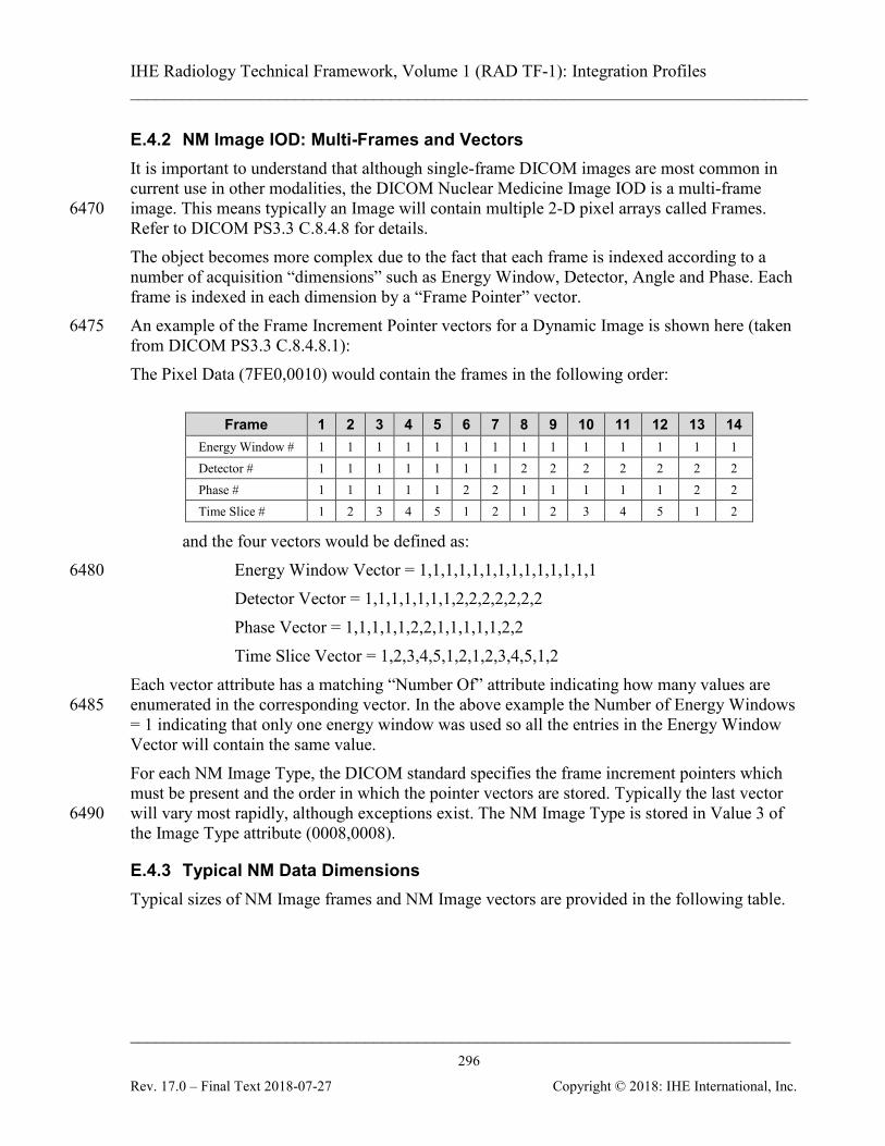
IHE Radiology Technical Framework, Volume 1 (RAD TF-1): Integration Profiles ______________________________________________________________________________
____________________________________________________________________________ 296
Rev. 17.0 – Final Text 2018-07-27 Copyright © 2018: IHE International, Inc.
E.4.2 NM Image IOD: Multi-Frames and Vectors It is important to understand that although single-frame DICOM images are most common in current use in other modalities, the DICOM Nuclear Medicine Image IOD is a multi-frame image. This means typically an Image will contain multiple 2-D pixel arrays called Frames. 6470 Refer to DICOM PS3.3 C.8.4.8 for details. The object becomes more complex due to the fact that each frame is indexed according to a number of acquisition “dimensions” such as Energy Window, Detector, Angle and Phase. Each frame is indexed in each dimension by a “Frame Pointer” vector. An example of the Frame Increment Pointer vectors for a Dynamic Image is shown here (taken 6475 from DICOM PS3.3 C.8.4.8.1): The Pixel Data (7FE0,0010) would contain the frames in the following order:
Frame 1 2 3 4 5 6 7 8 9 10 11 12 13 14 Energy Window # 1 1 1 1 1 1 1 1 1 1 1 1 1 1 Detector # 1 1 1 1 1 1 1 2 2 2 2 2 2 2 Phase # 1 1 1 1 1 2 2 1 1 1 1 1 2 2 Time Slice # 1 2 3 4 5 1 2 1 2 3 4 5 1 2
and the four vectors would be defined as: Energy Window Vector = 1,1,1,1,1,1,1,1,1,1,1,1,1,1 6480 Detector Vector = 1,1,1,1,1,1,1,2,2,2,2,2,2,2 Phase Vector = 1,1,1,1,1,2,2,1,1,1,1,1,2,2 Time Slice Vector = 1,2,3,4,5,1,2,1,2,3,4,5,1,2
Each vector attribute has a matching “Number Of” attribute indicating how many values are enumerated in the corresponding vector. In the above example the Number of Energy Windows 6485 = 1 indicating that only one energy window was used so all the entries in the Energy Window Vector will contain the same value. For each NM Image Type, the DICOM standard specifies the frame increment pointers which must be present and the order in which the pointer vectors are stored. Typically the last vector will vary most rapidly, although exceptions exist. The NM Image Type is stored in Value 3 of 6490 the Image Type attribute (0008,0008).
E.4.3 Typical NM Data Dimensions Typical sizes of NM Image frames and NM Image vectors are provided in the following table.
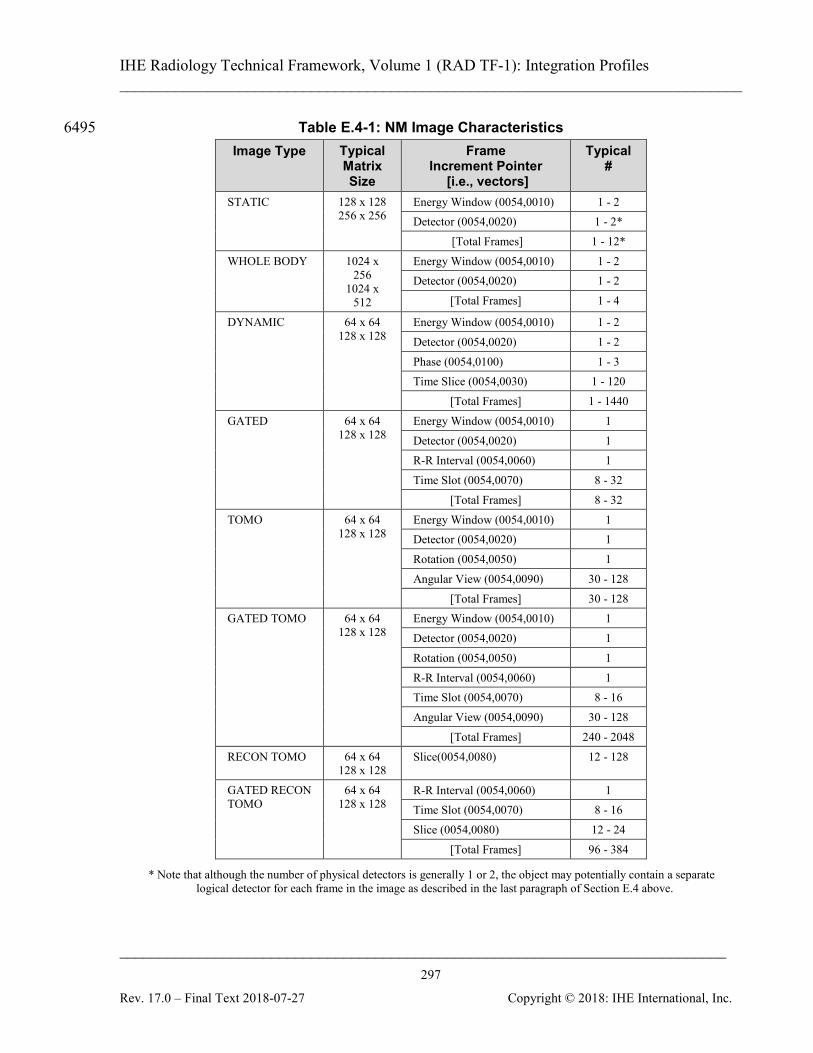
IHE Radiology Technical Framework, Volume 1 (RAD TF-1): Integration Profiles ______________________________________________________________________________
____________________________________________________________________________ 297
Rev. 17.0 – Final Text 2018-07-27 Copyright © 2018: IHE International, Inc.
Table E.4-1: NM Image Characteristics 6495 Image Type Typical
Matrix Size
Frame Increment Pointer
[i.e., vectors]
Typical #
STATIC 128 x 128 256 x 256
Energy Window (0054,0010) 1 - 2 Detector (0054,0020) 1 - 2*
[Total Frames] 1 - 12* WHOLE BODY 1024 x
256 1024 x
512
Energy Window (0054,0010) 1 - 2 Detector (0054,0020) 1 - 2
[Total Frames] 1 - 4
DYNAMIC 64 x 64 128 x 128
Energy Window (0054,0010) 1 - 2 Detector (0054,0020) 1 - 2 Phase (0054,0100) 1 - 3 Time Slice (0054,0030) 1 - 120
[Total Frames] 1 - 1440 GATED 64 x 64
128 x 128 Energy Window (0054,0010) 1 Detector (0054,0020) 1 R-R Interval (0054,0060) 1 Time Slot (0054,0070) 8 - 32
[Total Frames] 8 - 32 TOMO 64 x 64
128 x 128 Energy Window (0054,0010) 1 Detector (0054,0020) 1 Rotation (0054,0050) 1 Angular View (0054,0090) 30 - 128
[Total Frames] 30 - 128 GATED TOMO 64 x 64
128 x 128 Energy Window (0054,0010) 1 Detector (0054,0020) 1 Rotation (0054,0050) 1 R-R Interval (0054,0060) 1 Time Slot (0054,0070) 8 - 16 Angular View (0054,0090) 30 - 128
[Total Frames] 240 - 2048 RECON TOMO 64 x 64
128 x 128 Slice(0054,0080) 12 - 128
GATED RECON TOMO
64 x 64 128 x 128
R-R Interval (0054,0060) 1 Time Slot (0054,0070) 8 - 16 Slice (0054,0080) 12 - 24
[Total Frames] 96 - 384
* Note that although the number of physical detectors is generally 1 or 2, the object may potentially contain a separate logical detector for each frame in the image as described in the last paragraph of Section E.4 above.
IHE Radiology Technical Framework, Volume 1 (RAD TF-1): Integration Profiles ______________________________________________________________________________
____________________________________________________________________________ 298
Rev. 17.0 – Final Text 2018-07-27 Copyright © 2018: IHE International, Inc.
E.5 NM Display
E.5.1 NM Intensity and Color Mapping The control of display intensities in Nuclear Medicine is different than that used for CT or MR 6500 images due to inherent differences in the modality imaging process and the resulting image characteristics. In CT images are characterized by the fact that the pixel values represent Hounsfield units. Bone is represented by a well-known value plus or minus a typical range. Soft tissues are represented by another well-known value plus or minus a range. In this space it makes sense to provide 6505 controls for selecting a Window Center and a Window Width. In NM images, the pixel values typically represent radioactivity “counts”. Due to differences in radiopharmaceutical type, dose, time between injection and imaging, length of scan, overlying tissue density, metabolic processes and many other things, the pixel values cannot be considered strictly quantitative. Further, the image is often characterized by very high intensity “hot spots” 6510 where a very high concentration of tracer may have accumulated; and by a low level of background activity (“noise”) from non-specific uptake and scatter. For such images, it is appropriate to provide a control that would allow setting a threshold level to cut out the low level background, and another threshold to cut off the high level hot spots which might otherwise obscure mid-range intensities. 6515 Control of NM display intensities is therefore based on Upper and Lower Window Levels. These are different than Window Width and Center but the two are readily interchangeable by a simple linear mathematical transform.
Window Upper = Window Center + ½ Window Width Window Lower = Window Center - ½ Window Width 6520
Or conversely, Window Width = Window Upper - Window Lower Window Center = (Window Upper + Window Lower) / 2
NM pixel values can generally be represented in 16 bits of data. The Window Upper and Lower Levels indicate the current range of pixel values of interest. It is recommended that the upper and 6525 lower window values be displayed in the interface. Some NM datasets may contain very high pixel values. To display the images, it is generally necessary to map the NM Image pixel values into the range of grey levels which can be displayed by the hardware (most displays have much fewer discernible grey levels than there are pixel values in the dataset). 6530 Generally the display should be able to map pixel values to at least 128 display intensity levels. If the display supports more display intensity levels, the ability to map to more levels is preferred, if the display is only capable of fewer display intensity levels, it is acceptable to map to fewer levels. Mapping to 64 display intensity levels is also acceptable if it is necessary to display multiple color scales (see below) at the same time. 6535
IHE Radiology Technical Framework, Volume 1 (RAD TF-1): Integration Profiles ______________________________________________________________________________
____________________________________________________________________________ 299
Rev. 17.0 – Final Text 2018-07-27 Copyright © 2018: IHE International, Inc.
If the mapping is done only once when the image is first loaded then the presence of a small number of very high pixel values will result in most of the available display levels being “wasted” on a small number of pixels, leaving very little contrast in the rest of the image. To make effective use of the available display intensity contrast, it is useful to do rescaling after each Window Level adjustment, or to provide a way to control the maximum pixel value used 6540 for mapping. A similar problem (and solution) occurs when switching between examining bone and soft tissue windows in a CT image. If presentation state information is available with the images, it is generally preferred to use it for the initial display. Note that the Window Center and Window Width attributes in the presentation state object will also map to Upper and Lower Window values as described above. 6545 In the absence of presentation state information, it would make sense to display the framesets initially with the Upper and Lower Window Levels set based on the algorithm above and the values stored in the Window Center (0028,1050) and Window Width (0028,1051) attributes of the image data. In the absence of Window Center and Width values, a possibly viable setting may be the Lower 6550 Window level set to zero and the Upper Window Level set to the maximum pixel value of the frameset. Typical Nuclear Medicine clinical practice also differs from CT and MR in the prevalence of applying pseudo-color lookup tables or “color-scales” to the grayscale data during review. This is done to enhance particular features of the data in certain ways. 6555 Different sites, and sometimes different radiologists within each site, will generally have strong preferences about which color-scales they use for various pathologies in various types of NM studies. It is not unusual for NM review stations to have dozens of color-scales available. The ability for users to edit and/or create new pseudo-color lookup tables on the Image Display is occasionally useful but not required. Far more useful is the ability to install a preferred 6560 collection of color-scales on the system. The Society of Nuclear Medicine (SNM) has plans to act as a repository for a collection of common and popular color-scales. Since exported Result Screens in NM almost always contain image data, many users will want to be able to able to apply a pseudo-color lookup table and the ability to adjust Upper and Lower Window Levels of monochrome Secondary Capture and Multi-Frame Secondary Capture Images 6565 which have a modality type of NM. It may be unavoidable and would generally be acceptable that this could change the display values for any included graphics and annotations.
E.5.2 NM Image Resizing NM Images typically range in size from 64x64 to 512x1024 with the majority of the frames at the smaller end of the spectrum. Such small images must be enlarged on the display to be 6570 clinically useful, adding unnecessary steps to the reading radiologists’ workflow. A common mistake of general purpose display systems is to initially display these 64x64 frames at “full resolution” which results in a screen of “postage stamps”.
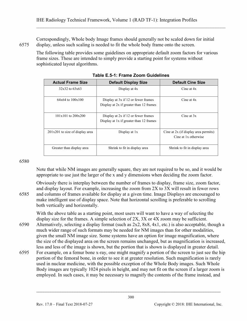
IHE Radiology Technical Framework, Volume 1 (RAD TF-1): Integration Profiles ______________________________________________________________________________
____________________________________________________________________________ 300
Rev. 17.0 – Final Text 2018-07-27 Copyright © 2018: IHE International, Inc.
Correspondingly, Whole body Image frames should generally not be scaled down for initial display, unless such scaling is needed to fit the whole body frame onto the screen. 6575 The following table provides some guidelines on appropriate default zoom factors for various frame sizes. These are intended to simply provide a starting point for systems without sophisticated layout algorithms.
Table E.5-1: Frame Zoom Guidelines Actual Frame Size Default Display Size Default Cine Size
32x32 to 63x63 Display at 4x
Cine at 4x
64x64 to 100x100 Display at 3x if 12 or fewer frames Display at 2x if greater than 12 frames
Cine at 4x
101x101 to 200x200 Display at 2x if 12 or fewer frames Display at 1x if greater than 12 frames
Cine at 3x
201x201 to size of display area Display at 1x
Cine at 2x (if display area permits) Cine at 1x otherwise
Greater than display area Shrink to fit in display area
Shrink to fit in display area
6580 Note that while NM images are generally square, they are not required to be so, and it would be appropriate to use just the larger of the x and y dimensions when deciding the zoom factor. Obviously there is interplay between the number of frames to display, frame size, zoom factor, and display layout. For example, increasing the zoom from 2X to 3X will result in fewer rows and columns of frames available for display at a given time. Image Displays are encouraged to 6585 make intelligent use of display space. Note that horizontal scrolling is preferable to scrolling both vertically and horizontally. With the above table as a starting point, most users will want to have a way of selecting the display size for the frames. A simple selection of 2X, 3X or 4X zoom may be sufficient. Alternatively, selecting a display format (such as 2x2, 8x8, 4x1, etc.) is also acceptable, though a 6590 much wider range of such formats may be needed for NM images than for other modalities, given the small NM image size. Some systems have an option for image magnification, where the size of the displayed area on the screen remains unchanged, but as magnification is increased, less and less of the image is shown, but the portion that is shown is displayed in greater detail. For example, on a femur bone x-ray, one might magnify a portion of the screen to just see the hip 6595 portion of the femoral bone, in order to see it at greater resolution. Such magnification is rarely used in nuclear medicine, with the possible exception of the Whole Body images. Such Whole Body images are typically 1024 pixels in height, and may not fit on the screen if a larger zoom is employed. In such cases, it may be necessary to magnify the contents of the frame instead, and
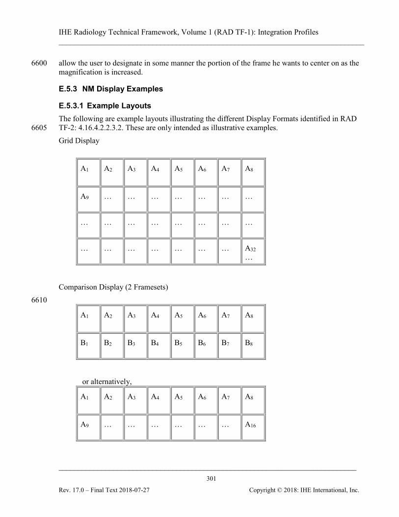
IHE Radiology Technical Framework, Volume 1 (RAD TF-1): Integration Profiles ______________________________________________________________________________
____________________________________________________________________________ 301
Rev. 17.0 – Final Text 2018-07-27 Copyright © 2018: IHE International, Inc.
allow the user to designate in some manner the portion of the frame he wants to center on as the 6600 magnification is increased.
E.5.3 NM Display Examples
E.5.3.1 Example Layouts The following are example layouts illustrating the different Display Formats identified in RAD TF-2: 4.16.4.2.2.3.2. These are only intended as illustrative examples. 6605 Grid Display
A1
A2 A3 A4 A5 A6 A7 A8
A9 … … … … … … …
… … … … … … … …
… … … … … … … A32 …
Comparison Display (2 Framesets) 6610
A1
A2 A3 A4 A5 A6 A7 A8
B1 B2 B3 B4 B5 B6 B7 B8
or alternatively,
A1
A2 A3 A4 A5 A6 A7 A8
A9 … … … … … … A16

IHE Radiology Technical Framework, Volume 1 (RAD TF-1): Integration Profiles ______________________________________________________________________________
____________________________________________________________________________ 302
Rev. 17.0 – Final Text 2018-07-27 Copyright © 2018: IHE International, Inc.
B1 B2 B3 B4 B5 B6 B7 B8
B9 … … … … … … B16
Whole body Display (2 Framesets, 2 Frames each) 6615
A1
A2
B1
B2
Fit Display (3 images, from 3 series with two frames each)
A1 A2 B1 B2
C1
C1
MPR Display (one transaxial volume, with a supplied or generated MIP cine display) 6620

IHE Radiology Technical Framework, Volume 1 (RAD TF-1): Integration Profiles ______________________________________________________________________________
____________________________________________________________________________ 303
Rev. 17.0 – Final Text 2018-07-27 Copyright © 2018: IHE International, Inc.
Transaxial Sagittal
Coronal
MIP (cine)
Note that the MIP is not strictly part of the MPR display, but since it is frequently useful, some vendors provide it. 6625 or alternatively,
Coronal y - 1
Coronal y
Coronal y + 1
Axial z - 1
Axial z
Axial z + 1
Sagittal n - 1
Sagittal n
Sagittal n + 1
Cine Display (three images from 3 series, each cycling synchronously)
A1-32 B1-32 C1-32
IHE Radiology Technical Framework, Volume 1 (RAD TF-1): Integration Profiles ______________________________________________________________________________
____________________________________________________________________________ 304
Rev. 17.0 – Final Text 2018-07-27 Copyright © 2018: IHE International, Inc.
E.5.3.2 Clinical Examples 6630 This section provides examples and clarifications on typical patterns of display for NM Images. This section should not be considered as an attempt to address hanging protocols. This is a complex topic which DICOM is working on. Once that work is complete, NM and Radiology in general would benefit from that work being included in the IHE Framework. This section is not intended to supplant that. 6635 See RAD TF-2: 4.16.4.2.2.3 for a description of some of the display related capabilities referred to in these examples. Example 1: Cardiac Study The user selects a Tomo stress series, several static result screens (secondary captures), another Tomo rest series, and a dynamic result screen (multi-frame secondary capture). 6640 The user would like to see both Tomo images together in a Row Display and be able to view them synchronously in Cine display, preferably with a method for adjusting the cine speed. Next the user would like to step forward and backward through each of the secondary capture result screens (which may be stored in a set of Secondary Capture images or in a single Multi-Frame Secondary Capture image without a cine module). 6645 The user would also like to review the dynamic result screen in cine mode. It is useful to be able to adjust the cine speed. Systems unable to cine the result screen at 8 frames/sec or faster would have limited clinical usefulness. Example 2: Lung Perfusion Study The user selects 4 Static series containing a total of 8 frames. The user would like to see all 8 6650 frames in a Fit Display (preferably with the frames resized to 256x256) Example 3: Ventilation-Perfusion Study The user selects the (several) series corresponding to lung perfusion imaging, and the (several) series corresponding to a lung ventilation imaging. The user expects to be able to review the ventilation and perfusion frames together in a Fit Display. The user may wish to adjust each 6655 series’ intensities and the zoom factor. It may be useful to select several series and adjust the intensities together. Example 4: Gastro-intestinal Bleed Study The user selects 2 dynamic images containing anterior and posterior frames from a two-phase 90 minute gastro-intestinal bleeding exam, with a grand total of 300 frames. The user expects to be 6660 able to page through the frames (showing them all at once would make the frames too small) in a Grid Display. The user would also expect to select one or other view, or one of the phases and view the frameset in a Grid Display.
IHE Radiology Technical Framework, Volume 1 (RAD TF-1): Integration Profiles ______________________________________________________________________________
____________________________________________________________________________ 305
Rev. 17.0 – Final Text 2018-07-27 Copyright © 2018: IHE International, Inc.
Finally the user would view a cine (perhaps two cines, one anterior frameset and one posterior 6665 frameset, or a single cine that allows the user to cine one view or the other independently). Example 5: Renal Study The user selects a dynamic study. The user expects to see a Grid Display to page through the frames and to be able to cine the time vector. When more than one phase is present, it is useful to be able to control the upper and lower levels 6670 of the phases separately. A user may wish to select a frame set corresponding to the first phase of a Dynamic Image, which represents the flow portion of the exam, and lower the Upper Window Level to increase the visibility of these “low-count” frames. The second phase frame set, which contains images which are inherently much brighter, should be left unadjusted. In general, typical display formats for each of the NM Image Types would be as follows: 6675 STATIC: Simple display. Typically several images displayed at once (for example in a Fit display). While the default order of frames in the object is sorted by Energy Window then Detector, it is generally more useful to present them in Detector/Energy Window order or sorted by acquisition time. Example: 12 view static WHOLE BODY: Side by side display of two rectangular images (i.e., the Whole body display). 6680 DYNAMIC: Cine through all frames of all phases from one detector and one energy window, in order. It is also useful to display in a Grid or Row display. Generally a different window level applies to each phase. Processing (not required by the NM Profile) includes plotting time activity through user selected areas of the image. GATED: Cine through the frames from one detector/energy window, in time order. Processing 6685 (not required by the NM Profile) can include time activity curves, heart wall edge detection and motion tracking, etc. Typically several images displayed at once. TOMO: Cine all frames from one (logical) detector in rotational angle order. Recommend ability to cine back and forth (i.e., frames 1 to n, followed by frames n to 1), in addition to the standard forward cine. 6690 RECON TOMO: Display all slices in spatial order. Typical display actions can include reorientation to other viewing planes (MPR). Processing (not required by the NM Profile) can include oblique reorientation to cardiac relative views, creation of MIP images, etc. Example: Stress-Rest in a Row Layout display, or a single dataset in an MPR Display. GATED TOMO: Cine all frames (angular views) from one energy window, one (logical) 6695 detector, one rotation, one R-R interval, and one Time Slot, or all Time Slots from one energy window, detector, rotation, R-R interval, and Angular View. Some users do not review these images unless data acquisition problems are suspected. GATED RECON TOMO: Cine all frames from one R-R Interval and one Time Slot. Typical processing includes all functions done to RECON TOMO images, plus special cardiac 6700 processing such as bull’s-eye plot creation.
IHE Radiology Technical Framework, Volume 1 (RAD TF-1): Integration Profiles ______________________________________________________________________________
____________________________________________________________________________ 306
Rev. 17.0 – Final Text 2018-07-27 Copyright © 2018: IHE International, Inc.
Examples of simultaneous cine: three TOMO images (used for quality control of cardiac raw projections); three GATED planar exams (RVGs); or 2 detectors from a dynamic image. Note that in the U.S., ACR accreditation requires the ability to label displayed images with the patient name, patient age (or date of birth), patient identification number, date of exam, 6705 institution name, and some means of identifying the technologist who performed the study. The Nuclear Medicine Accreditation Committee of the ACR has further required that laterality and orientation information also be provided.
Appendix F: Security Environment Considerations IHE compliant systems usually process private healthcare information. This is subject to national 6710 privacy regulations, and possibly other state and contractual requirements. The IHE profiles do not fully define the security mechanisms necessary to protect this information. The ITI Audit Trail and Node Authentication (ATNA) Profile (ITI TF-1: 9) provides one component of this solution. IHE assumes that actors will be installed on nodes with the following characteristics: 6715
• Each node has a security policy and procedure that applies to its operation. This is assumed to be part of the healthcare enterprise security policy.
• Any user (human, or application process) external to the node boundaries is submitted to an access control procedure in which the user/application will be authenticated.
• All required audit trail events are captured and recorded. 6720 The profiles in this framework assume the following environment:
• Physical Security Environment
• The equipment is assumed to be located in a physically protected and actively monitored area. This is normally the case with modality equipment because of other patient safety, privacy, and operational concerns. Similarly, the HIS systems and 6725 various archives are normally protected. Equipment like PACS workstations are sometimes placed in unprotected areas, but it is usually located where hospital staff monitors and limit access. It assumes that the threat of equipment modification is protected against by means of the physical security mechanisms.
• The network equipment that connects the computers is also assumed to be physically 6730 protected against unauthorized connections and unauthorized modifications. In the treatment areas of most hospitals the network equipment is in ceilings, cableways, locked cabinets, and other protected areas. There is usually staff present to monitor that no unauthorized activity is taking place.
• Local procedures and operations will be in place to ensure that the physical security 6735 assumptions are valid for other areas of the hospital, such as administrative offices, that may be at greater risk.
IHE Radiology Technical Framework, Volume 1 (RAD TF-1): Integration Profiles ______________________________________________________________________________
____________________________________________________________________________ 307
Rev. 17.0 – Final Text 2018-07-27 Copyright © 2018: IHE International, Inc.
• Remote locations, especially home offices, are not physically protected. Other means will be used to provide equivalent protection. This may include the use of technology such as VPN connections or HTTPS encryption. Use of encryption or VPN is not a 6740 complete replacement for physical security but may be part of an overall protection system.
• The home computer that is used for both personal and professional purposes is difficult to protect. It will be protected from inadvertent modification by malicious software or its use will be prohibited. 6745
• Network Security Environment
• In addition to the physical security of the network, there will be protection against network access by unsupervised systems. This is typically provided by mechanisms such as firewalls and VPNs.
The threat profile is assumed to be: 6750
• Accidental and inadvertent misuse
• Individual abuse for personal gain, malice, revenge, or curiosity. The abusers are assumed to have only limited access to the underlying systems and software. They are not expert at the internal structure of the systems.
• Random untargeted abuse, such as from an Internet hacker. 6755 The threat profile also assumes that the following threats are either not present or otherwise protected.
• Individual abuse by a system administrator, system developer, or other expert.
• Military or hostile government action
• Organized criminal attack 6760
IHE addresses only those security requirements related to IT systems within the scope of IHE healthcare applications. It does not address security requirements for defending against network attacks, virus infection, etc. IHE does not mandate the use of encryption because the performance impact of current encryption algorithms is excessive. Most hospital networks provide adequate security through 6765 physical and procedural mechanisms. The additional performance penalty for encryption is not justified for these networks. The profiles permit the use of encryption so that it can be used as part of an overall security plan.
IHE Radiology Technical Framework, Volume 1 (RAD TF-1): Integration Profiles ______________________________________________________________________________
____________________________________________________________________________ 308
Rev. 17.0 – Final Text 2018-07-27 Copyright © 2018: IHE International, Inc.
Appendix G: Patient Information Reconciliation for XDS-I.b 6770 (INFORMATIVE)
Patient Information Reconciliation (PIR) workflow within a local domain is well understood and addressed within the IHE PIR Integration Profile. However, within an XDS affinity domain, there is the added complexity of managing patient information within the XDS Document Registry and synchronizing data between the document sources, repository and registry. 6775 The XDS Profile does not address the challenges of PIR. The reason for this is scope management (at the time of writing the initial XDS Profile) as well as a lack of content profiles to stress the PIR issue. It is the intent of the ITI Technical Committee to address the issue of PIR within XDS in due course. Given that PIR will be addressed within the XDS Profile, this Appendix is considered 6780 informative and serves to demonstrate that imaging information content does not introduce any new or imaging information content specific PIR issues.
G.1 Context and Assumptions
G.1.1 XDS Affinity Domain Assumptions • The Document Registry assumes that all documents have a normalized patient ID 6785
pertaining to the XDS Affinity Domain. Therefore:
• The XDS Affinity Domain must have a Patient Identification Domain in order to realize normalized patient IDs.
• The XDS Affinity Domain must have a Patient Identity Source Actor
• To simplify description in this section, the nomenclature for the XDS Affinity 6790 Domain will be “XAD”.
• A Document Source is responsible for obtaining the XAD patient ID for registering the document within the registry. The XAD patient ID that is obtained is only used for this purpose and is not used to update any patient ID’s within the document. Patient ID’s within the document shall remain unchanged by the registration process 6795
• A Document Consumer is expected to query the Document Registry using the XAD patient ID
• The Registry can only accept a document if the document has a valid XAD patient ID
• The Registry must check to see if the XAD patient ID is valid. This can be done in two ways: 6800
• Query the XAD Patient Identity Source to see if the XAD patient ID exists – not supported at this time

IHE Radiology Technical Framework, Volume 1 (RAD TF-1): Integration Profiles ______________________________________________________________________________
____________________________________________________________________________ 309
Rev. 17.0 – Final Text 2018-07-27 Copyright © 2018: IHE International, Inc.
• Maintain all XAD patient IDs in the registry irrespective of whether there are documents for that patient i.e., keep in synch with the XAD Patient Identity Source – this is the expected model 6805
• The Registry cannot accept a document with an OID that is already registered
• If a document is submitted that has the OID of a document already registered, the Registry will reject the submission
• If a document is re-submitted and, thereby, is identical to a document already submitted, the Registry will reject the submission 6810
G.1.2 Metadata in the Document Registry • The XAD patient ID is the only piece of metadata that can be reliably used to query for a
patient
• The Registry maintains supporting patient information such as Name, Sex, DoB, etc. but is NOT obligated to ensure the referential integrity of this data. Therefore: 6815
• This information is NOT used for query matching (but is only used for audits and potential verification of Document Consumers)
• There is no requirement for the XDS Document Registry to verify that the meta-data in the Registry corresponds to the patient information in the document itself
• The Registry does track the local domain source patient ID, but this is not used for query 6820 matching
G.1.3 Patient Identity Management in the XDS Registry • The Registry keeps a list of known XAD patient IDs
• The Registry associates documents with the patient IDs
• The Registry receives patient “merge” notifications from the XAD Patient Identity 6825 Source
• The Registry is responsible for updating XAD patient IDs associated with documents
• The Registry does not update metadata nor document content
• If the clinical content of a document has changed, the Document Source is responsible for updating the Document Repository and Document Registry 6830
G.1.4 Expected Implementation Models for Patient Identity Management In a cross enterprise scenario, we assume that there are multiple patient identity domains
• Local patient identity domains that support one or more enterprises. These pertain to Document Sources and Document Consumers
• Affinity Domain patient identity domain 6835
IHE Radiology Technical Framework, Volume 1 (RAD TF-1): Integration Profiles ______________________________________________________________________________
____________________________________________________________________________ 310
Rev. 17.0 – Final Text 2018-07-27 Copyright © 2018: IHE International, Inc.
Each patient identity domain has a Patient Identity Source. In the case of local domains, this is likely to be an ADT system. For the Affinity Domain, this is yet another patient registry. A participating enterprise may deploy a Patient Identifier Cross-Referencing (PIX) Manager to cross-map Patient ID in the local domain to Patient ID in XAD domain. In such cases, the Cross Reference Manager will interact with the Affinity Domain Patient Identity Source. 6840 Document sources and consumers are required to obtain a normalized XAD patient ID. The mechanism for achieving this is dependent on the implementation of patient identity feeds and patient identity cross-reference manages within the Affinity Domain. For example, where local domains have Patient Identity X-ref managers, the document sources and consumers obtain the normalized XAD patient ID from the Affinity Domain patient identity source via the X-ref 6845 managers. The document sources and consumers can also obtain the XAD patient ID using other methods such as IHE PDQ or non- IHE approaches. For the sake of discussion, no assumptions are made on how document sources and consumers interact with the XAD patient identity domain – it could be directly or through a local domain X-ref manager. 6850 Further information on integrating Source and Consumer actors in XDS and XDS-I.b with other IT Infrastructure actors for exchanging patient identifying data across identity domains can be found in ITI TF-1: E.3, E.4, E.5.
G.2 Patient Information Reconciliation (PIR) in an Affinity Domain PIR workflow within a local domain is well understood and addressed within the IHE PIR 6855 Integration Profile. However, within an XDS affinity domain, there is the added complexity of managing patient information within the XDS Registry and synchronizing data between the document sources, repository and registry.
G.2.1 Patient Merge within XAD Patient Identity Domain • XAD patient identity domain merges two patients 6860
• Document sources are unaware of the merge transaction within XAD patient identity domain
In this situation:
• XDS Registry receives a merge notification from the XAD patient identity source and applies merge logic to the registry 6865
• Document consumers have continued access to documents pertaining to the patient since consumers are expected to obtain the XAD patient ID for the patient at the time of querying the Registry
• Document sources are unaware of the merge transaction that occurred in the XDS registry and do not need to be made aware of this merge. The reasons for this are: 6870
• Consumers have continued access to the document
IHE Radiology Technical Framework, Volume 1 (RAD TF-1): Integration Profiles ______________________________________________________________________________
____________________________________________________________________________ 311
Rev. 17.0 – Final Text 2018-07-27 Copyright © 2018: IHE International, Inc.
• The document source must query for the XAD patient ID before attempting to interact with the repository and registry. As such, the document source will have an updated XAD patient ID at the time of interacting with the registry.
• When a document source wishes to submit a change to the document: 6875
• The document source must query for the XAD patient ID before registering the new document
• The document source must register the new document with a request to deprecate the old document. From the document source’s perspective, the old document is still associated with the original XAD patient ID. By virtue of obtaining a new XAD 6880 patient ID for the patient, the document source must assume that a patient merge has taken place and use the new XAD patient ID to deprecate the old document
The process flow is described in more detail as follows: Scenario:
• Key identifier for a patient within the XAD patient identity domain changes, such as 6885 health number
• The XAD patient identity source merges two patients Process Steps:
1. The XAD patient identity source sends a “merge” notification to the XDS Registry 6890 2. XDS Registry applies merge logic to the patients within the merge notification
• The metadata in the registry will be accurate with the exception of the source patient ID
G.2.2 Local Domain Patient Update - XAD Domain Patient ID does not change 6895
• Demographics for the patient change
• Local domain patient ID does NOT change
• XAD patient ID does NOT change In this scenario: 6900
• XDS Registry does nothing since the XAD patient ID has not changed
• If a document source changes the patient demographics content of a document and a new document is created then this document should be registered with the XDS repository/registry as a replacement to the old document
IHE Radiology Technical Framework, Volume 1 (RAD TF-1): Integration Profiles ______________________________________________________________________________
____________________________________________________________________________ 312
Rev. 17.0 – Final Text 2018-07-27 Copyright © 2018: IHE International, Inc.
The process flow is described in more detail as follows: 6905 Scenario:
• Patient first name is corrected from “Jamie” to “James” in the local domain patient identity source
Process Steps: 6910
1. Update information flows from the local domain patient identity source (i.e., ADT) to the document source: image manager/archive.
• Document source updates its database to correct demographics
• Either: Document source does not change the document
• The Document Source does not update the repository/registry. In this scenario, the 6915 patient demographics: Name, DoB Sex, etc.; in the Document Source do not match those in the XDS Registry. This is acceptable in the XDS framework
• Or: Document source changes the document
• The Document Source updates the repository/registry with an addendum 6920
2. The Registry takes no action as the XAD patient ID has not changed
G.2.3 Local Domain Patient Update - XAD Domain Patient Merge • Demographics for the patient change
• Local domain patient ID does NOT change 6925
• XAD patient ID does change and triggers a merge within XAD domain
• Document sources are unaware of the merge transaction within XAD patient identity domain
In this scenario: 6930
• See Section G.2.1 Patient Merge within XAD Patient Identity Domain
The process flow is described in more detail as follows: Scenario:
• Patient last name is corrected from “Alfonsp” to “Alfonso” within local domain patient 6935 identity source

IHE Radiology Technical Framework, Volume 1 (RAD TF-1): Integration Profiles ______________________________________________________________________________
____________________________________________________________________________ 313
Rev. 17.0 – Final Text 2018-07-27 Copyright © 2018: IHE International, Inc.
• XAD domain patient identity source merges “Alfonsp: XAD-Pp” into “Alfonso: XAD-Pa” – patient “Alfonso” was already registered within the XAD domain with patient ID XAD-Pa
Process Steps: 6940
• See Section G.2.1 Patient Merge within XAD Patient Identity Domain
G.2.4 Local Domain Patient Merge – XAD Domain Patient ID does not change • Demographics for the patient changes
• Local domain patient identity source merges patient A with patient B 6945
• XAD patient ID for patient A and patient B are the same In this scenario:
• XDS Registry does nothing since the XAD patient ID for patient A and patient B is the same 6950
• Document sources apply merge logic to the documents within their database i.e., documents are now associated with a new local domain patient ID
• Document sources must now query XAD patient identity source to obtain the XAD patient ID for the merged patient
• The XAD patient ID is the same as already associated with the document: 6955
• If the document source does not change the document content, the document source does not need to interact with XDS Repository/Registry – status quo
• If the document source changes the patient demographics content of a document and a new document is created, then this document should be registered with the XDS repository/registry as a replacement to the existing document. 6960
The process flow is described in more detail as follows: Scenario:
• Patient last name is corrected from “Smythe” to “Smyth”
• ADT already has an entry for “Smyth”
• “Smythe” with local domain patient ID D-123 is merged with Smyth with local domain 6965 patient ID D-456
• XAD Patient Identity Source already recognized “Smythe: D-123” and “Smyth: D-456” as the same patient and, therefore, assigned each with the same XAD patient ID: XAD-Px
IHE Radiology Technical Framework, Volume 1 (RAD TF-1): Integration Profiles ______________________________________________________________________________
____________________________________________________________________________ 314
Rev. 17.0 – Final Text 2018-07-27 Copyright © 2018: IHE International, Inc.
Process Steps: 6970 1. Update information flows from the local domain patient identity source (i.e., ADT) to the
document source: image manager/archive.
• Document source applies merge logic to the database: documents for the merged patient are associated with the new patient ID
2. Document source queries the XAD patient identity domain to determine whether the 6975 XAD patient ID has changed for the merged documents. In this case the XAD patient ID does not change
3. Document source updates the demographics of the document
• Either: Document source makes no changes to the document – demographics are in the database 6980
• The Document Source need not update the repository/registry. In this scenario, the patient demographics in the Document Source do not match those in the XDS Registry. This is acceptable in the XDS framework
• Or: Document source changes the document
• The Document Source updates the repository/registry with an addendum 6985 4. The Registry takes no action as the XAD patient ID has not changed
G.2.5 Local Domain Patient Merge – XAD Domain Patient Merge • Demographics for the patient changes
• Local domain patient identity source merges patient A with patient B
• XAD patient IDs for patient A and patient B are different 6990
• Patient A is merged with patient B in the XAD domain patient identity source There are three situations that can occur:
1. XDS Registry merge prior to Document Source merge
• XDS Registry receives a merge notification from the XAD patient identity source and 6995 applies merge logic to the registry
• Document sources are unaware of the merge transaction that occurred in the XDS registry and do not need to know about this transaction (see Section G.2.1)
• Document consumers have continued access to documents pertaining to the patient since consumers are expected to obtain the XAD patient ID for the patient at the time 7000 of querying the Registry
IHE Radiology Technical Framework, Volume 1 (RAD TF-1): Integration Profiles ______________________________________________________________________________
____________________________________________________________________________ 315
Rev. 17.0 – Final Text 2018-07-27 Copyright © 2018: IHE International, Inc.
• Document sources apply merge logic to the documents within their database i.e., documents are now associated with a new local domain patient ID
• Document sources must now query XAD patient identity source to obtain the XAD patient ID for the merged patient 7005
• The XAD patient ID for the documents has changed:
• The document source changes the XAD patient ID associated with the documents – it can assume that the Registry has made this change as well
• If the document source does not change the document content, the document source does not need to interact with XDS Repository/Registry – status quo 7010
• If the document source changes the patient demographics content of a document and a new document is created then this document should be registered with the XDS repository/registry – the existing document is deprecated.
2. Document Source merge prior to XDS Registry merge 7015
• Document sources apply merge logic to the documents within their database i.e., documents are now associated with a new local domain patient ID
• Document sources must now query XAD patient identity source to obtain the XAD patient ID for the merged patient
• The XAD patient ID is the same as already associated with the document: 7020
• If the document source does not change the document content, the document source does not need to interact with XDS Repository/Registry – status quo
• If the document source changes the patient demographics content of a document and a new document is created, then this document should be registered with the XDS repository/registry as a replacement to the old document 7025
• XDS Registry receives a merge notification from the XAD patient identity source and applies merge logic to the registry
• Document sources are unaware of the merge transaction that occurred in the XDS registry and do not need to know about this transaction
• Document consumers have continued access to documents pertaining to the patient since 7030 consumers are expected to obtain the XAD patient ID for the patient at the time of querying the Registry
3. Document Source merge at same time as XDS Registry merge
• Document sources apply merge logic to the documents within their database i.e., 7035 documents are now associated with a new local domain patient ID
IHE Radiology Technical Framework, Volume 1 (RAD TF-1): Integration Profiles ______________________________________________________________________________
____________________________________________________________________________ 316
Rev. 17.0 – Final Text 2018-07-27 Copyright © 2018: IHE International, Inc.
• Document sources must now query XAD patient identity source to obtain the XAD patient ID for the merged patient
• The XAD patient ID is the same as already associated with the document
• XDS Registry receives a merge notification from the XAD patient identity source and 7040 applies merge logic to the registry
• Document source chooses to change the patient demographics content of a document and a new document is created. This document is registered with the XDS repository/registry:
• The XAD patient ID for this document has now been merged in the XDS Registry 7045 and, therefore, is no longer valid
• The Registry will reject the document registration transaction as the XAD patient ID used in the transaction is no longer valid.
• Document sources must now query XAD patient identity source to obtain the XAD patient ID for the merged patient and re-register the document with the 7050 XDS repository/registry
Scenario:
• Patient last name is corrected from “Smythe” to “Smyth”
• ADT already has an entry for “Smyth” 7055
• Smythe: patient ID D-123 is merged with Smyth: patient ID D-456
• XAD Patient Identity Source has separate entries for both “Smythe: XAD-Pc” and “Smyth: XAD-Pf”. As such, it merges these two patients in to “Smyth: XAD-Pf”.
Process Steps: 7060 The process flow is a combination of the previous scenario process flows and, thereby, not repeated here.
IHE Radiology Technical Framework, Volume 1 (RAD TF-1): Integration Profiles ______________________________________________________________________________
____________________________________________________________________________ 317
Rev. 17.0 – Final Text 2018-07-27 Copyright © 2018: IHE International, Inc.
Appendix H: Security considerations for XDS-I.b (informative) This IHE profile does not specify all the details of the security environment for exchanging 7065 radiology information. The IHE includes several security profiles that apply to the XDS/ XDS-I.b use. The use of these security profiles in the first trial implementation for XDS-I.b will likely be optional. The security profiles make assumptions about the overall security environment and are configurable to adapt to different security requirements. Figure H-1 shows typical transactions for XDS-I.b. Each transaction goes through security and 7070 privacy controls. This figure illustrates use of firewall access points and TLS controls for all XDS-I.b participants, including the Imaging Document Source. The firewalls may have simple easy to implement rules or more complex rules depending upon local policies. The flows shown in Figure H-1 are described in more detail below: Flow #1, The Store Images, etc. transactions: 7075 a) Internal firewall rules I: - Simple rules: “outgoing HTTP is OK” - Complex rules: examine source IP, destination IP, HTTP headers to decide whether to permit the connection. b) TLS within each actor: 7080 - IM/IA: Is this really the authorized Image Document Source that was requested? - Repository: Is this really an authorized IM/IA? c) Once the TLS connection is established there is further processing, generation of audit records, etc. 7085 Flow #2, The Provide and Register Imaging Document Set transaction: a) does not cross a firewall b, c) TLS, authorization, auditing as above. Flow #3, The Register transaction 7090 a) External firewall rules II: - Simple: Outgoing HTTP is OK - Complex: examine source IP, destination IP, HTTP headers to decide whether to permit the connection. b, c) TLS, authorization, auditing as above. 7095
IHE Radiology Technical Framework, Volume 1 (RAD TF-1): Integration Profiles ______________________________________________________________________________
____________________________________________________________________________ 318
Rev. 17.0 – Final Text 2018-07-27 Copyright © 2018: IHE International, Inc.
Flow #4, Query Documents transaction: a) External firewall access rules II: - Simple: Incoming HTTP to the DMZ is OK - Complex: very tricky given many different uses for HTTP incoming by different web 7100 applications. b, c) TLS, authorization, auditing as above. Flow #5, Retrieve Images, etc. transactions: a) External firewall access rules III: 7105 - Simple: Incoming DICOM is only permitted from authorized affinity domain IP blocks. - Complex: Examine the DICOM retrieve connection initiator and the targeting acceptor IP addresses, and permit only connections between a priori authorized pairs of initiator and acceptor. b, c) TLS, authorization, auditing as above. 7110 This example shows access for both HTTP and DICOM traffic. It is easier to get multi-layer protection for the DICOM traffic because it is easily differentiated from the many diverse uses of HTTP for web applications and services. Then the TLS security, actor authorization rules, and auditing are applied to all traffic regardless of type. 7115
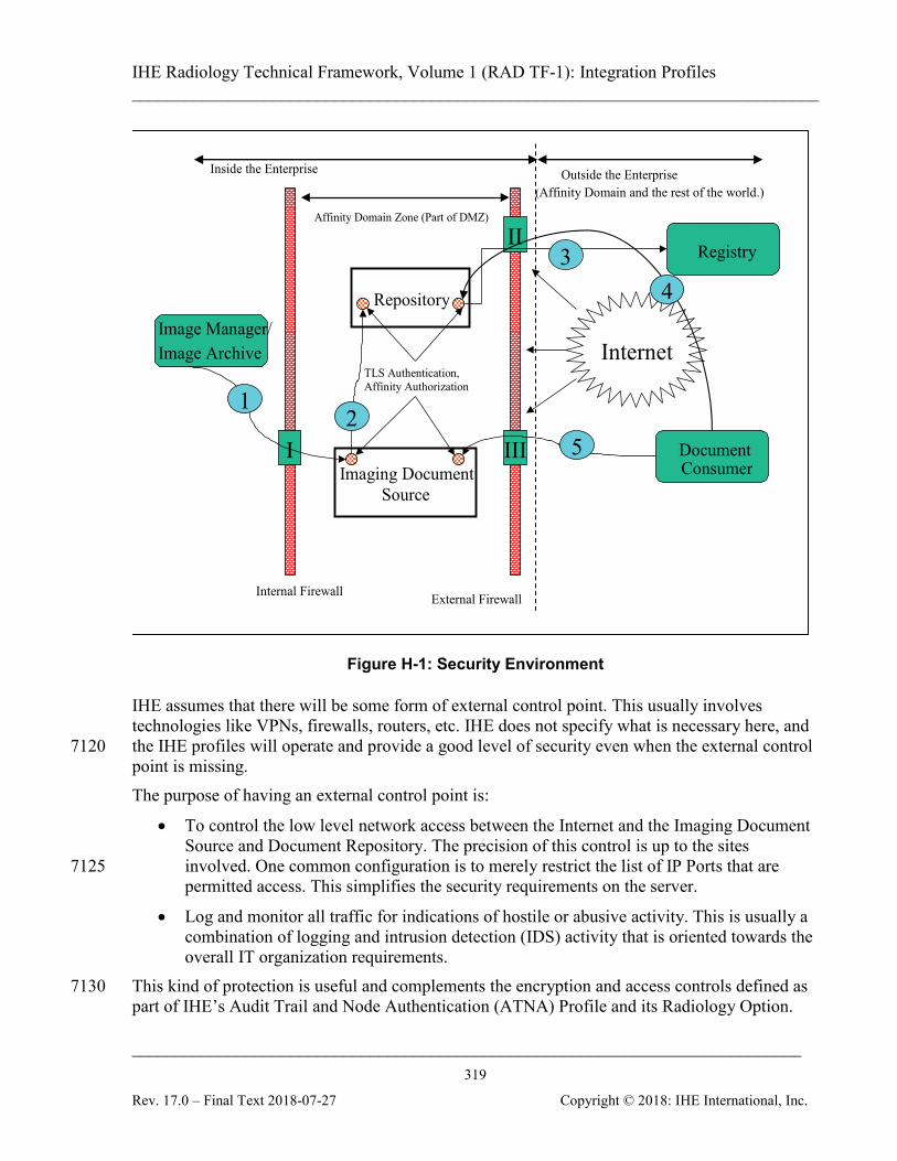
IHE Radiology Technical Framework, Volume 1 (RAD TF-1): Integration Profiles ______________________________________________________________________________
____________________________________________________________________________ 319
Rev. 17.0 – Final Text 2018-07-27 Copyright © 2018: IHE International, Inc.
Inside the Enterprise Outside the Enterprise
(Affinity Domain and the rest of the world.)
II
I III
Internal Firewall External Firewall
Affinity Domain Zone (Part of DMZ)
Repository
Imaging Document Source
Image Manager/ Image Archive Internet
Document Consumer
Registry
TLS Authentication, Affinity Authorization
1 2
3
4
5
Figure H-1: Security Environment
IHE assumes that there will be some form of external control point. This usually involves technologies like VPNs, firewalls, routers, etc. IHE does not specify what is necessary here, and the IHE profiles will operate and provide a good level of security even when the external control 7120 point is missing. The purpose of having an external control point is:
• To control the low level network access between the Internet and the Imaging Document Source and Document Repository. The precision of this control is up to the sites involved. One common configuration is to merely restrict the list of IP Ports that are 7125 permitted access. This simplifies the security requirements on the server.
• Log and monitor all traffic for indications of hostile or abusive activity. This is usually a combination of logging and intrusion detection (IDS) activity that is oriented towards the overall IT organization requirements.
This kind of protection is useful and complements the encryption and access controls defined as 7130 part of IHE’s Audit Trail and Node Authentication (ATNA) Profile and its Radiology Option.

IHE Radiology Technical Framework, Volume 1 (RAD TF-1): Integration Profiles ______________________________________________________________________________
____________________________________________________________________________ 320
Rev. 17.0 – Final Text 2018-07-27 Copyright © 2018: IHE International, Inc.
The internal network is probably divided into two or more zones that are isolated by internal control points. These internal control points are similar to the external control point, but usually are much more permissive in terms of the traffic that they allow. They exist both to detect problems and to provide a means of rapidly isolating portions of the network in the event of a 7135 security breach. The Imaging Document Source is assumed to be located in the zone labeled the “Affinity Domain Zone”. This might also be part of a general DMZ (De-Militarized Zone) for the organization or it might be a special zone reserved exclusively for Affinity Domain activities. There are cost and functionality tradeoffs involved in making that decision and the IHE profiles 7140 support both approaches. IHE will specify the minimum-security requirements for the Imaging Document Source. It will be expected to comply with the IHE ITI ATNA (Audit Trail and Node Authentication) Integration Profile. There may be multiple Imaging Document Sources in the Affinity Domain Zone and they will all be expected to comply with the ATNA Profile. This profile mandates: 7145
• All connections that might transfer protected health information (PHI) must utilize TLS configured to:
• Authenticate both machines involved
• Ensure that all traffic is encrypted, either directly by TLS or by means of equivalent protection such as VPN. 7150
• Enforce access control to the system
• Provide a detailed security audit trail for all PHI related activity and information transfers
The TLS protocol is also widely known as HTTPS. The ATNA Profile mandates this protection for any DICOM, HL7, HTTP or other protocols. There may be special auditing requirements for an XDS-I.b actor. For example, in the US there 7155 are HIPAA requirements for disclosure logs. Only the sites themselves can determine what belongs in a disclosure log. The ATNA logs were not directly intended for this purpose. The Imaging Document Source may be a system that is complete with its own image archive, or it may be a proxy machine that relays information to another machine, perhaps located in a private zone. This is considered an internal design issue by IHE. The XDS-I.b Profile specifies 7160 that the Imaging Document Source must support the XDS-I.b transactions, and does not specify the internal design. There are several important design considerations for securing XDS-I.b networks that must be made by the affinity domain and its members. These are:
1. What kind of external control points are used? IHE recommends that they be present, but 7165 does not profile them.
2. How to subdivide the enterprise network and whether to establish a dedicated Affinity Domain Zone. There is an advantage to creating an Affinity Domain Zone with just a few servers located in it:
IHE Radiology Technical Framework, Volume 1 (RAD TF-1): Integration Profiles ______________________________________________________________________________
____________________________________________________________________________ 321
Rev. 17.0 – Final Text 2018-07-27 Copyright © 2018: IHE International, Inc.
a. The log analysis is easier 7170 b. The certificate and TLS management for node authentication is easier c. The preparation of disclosure logs and the equivalent is easier. d. The internal control point reduces the risks from a breach of the Affinity Domain
Zone. 3. Whether User Authentication is needed. IHE provides both the Enterprise User 7175
Authentication (EUA) and Cross Enterprise User Assertion (XUA) Profiles. Use of user authentication permits additional information to be captured in the audit logs (e.g., the identity of the user) and permits additional access control in some situations. The issues that the affinity domain and sites must address are: a. What to do about automated processes, such as pre-fetch and email. These can be 7180
identified using node authentication via TLS as specified in ATNA, by using simple identity assertions.
b. How to handle delegation. Often it is clerks, nurses, etc. that are actually operating the computer to obtain the records for a patient, and it is someone else that will actually be examining the records. So the user authentication might not provide any 7185 further useful information. The IHE profiles do not determine these choices. Some reasonable selections include: 1. Not using user authentication. The ATNA ensures that the enterprise and the
machine are authenticated. These machines are already authenticated and trusted to protect PHI information. It may be impractical to track and coordinate the 7190 personnel activities across all the different organizations.
2. Though not specifically designed for this purpose, it is also possible that the XDS-I.b Profile is being used internally within a centrally controlled large organization, where the Kerberos based identity management of EUA is available. EUA can be used in such an intra-enterprise environment. EUA supports simple identity 7195 assertions. These are based on trusting the authenticated node to provide the correct identity of its user.
3. The use of XUA is optional. Where a human user is involved, XUA can be employed for cross-enterprise user identity assertion. If only machines are involved, the node authentication provided by ATNA should be sufficient. The 7200 use of XUA requires that the affinity domain establish the authentication policies, procedures, and have a supporting infrastructure of servers, etc. (This infrastructure may be provided by the local government or might need to be provided by the affinity domain.)
Note: In order to use the IHE XUA Integration Profile, the underlying application protocol must be able to carry a user 7205 identity assertion in its payload. While such a mechanism has been established in HL7 and HTTP/S, the mechanism to provide this for DICOM messages is still under development. Thus, XUA Profile cannot (yet) be employed when retrieving DICOM SOP Instances referenced in the manifest document.

IHE Radiology Technical Framework, Volume 1 (RAD TF-1): Integration Profiles ______________________________________________________________________________
____________________________________________________________________________ 322
Rev. 17.0 – Final Text 2018-07-27 Copyright © 2018: IHE International, Inc.
The affinity domain and individual site policies will determine the choices made. There are IHE profiles defined to address these alternatives. 7210
IHE Radiology Technical Framework, Volume 1 (RAD TF-1): Integration Profiles ______________________________________________________________________________
____________________________________________________________________________ 323
Rev. 17.0 – Final Text 2018-07-27 Copyright © 2018: IHE International, Inc.
Appendix I: Appendix I – Deployment of Dose Registries The Radiation Exposure Management Profile is intended to facilitate Dose Registry projects. Participating sites that have implemented the REM Profile can be depended on to provide data with known contents in a known format and will all support a common transport mechanism. See 7215 the Submit Dose Information transaction for details (RAD TF-3: 4.63). This appendix includes discussions of logistical issues related to the deployment of dose registries. This is not part of the normative text of the REM Profile, but the discussions here may be helpful when deploying and using the REM Profile.
I.1 Dose Registry Deployment Issues 7220
I.1.1 Code Set Management Although the REM Profile does manage to provide consistent dose data, for a Dose Registry to analyze dose objects and prepare summary statistics for a specific exam type, anatomy or pathology/indication, it will need to select/group dose objects based on exam type, anatomy or pathology/indication. 7225 If the different sites submitting data used consistent code sets for coding such details, this might be easy, but unfortunately, for technical and organizational reasons, such code set consistency is unlikely. Due to similar issues, consistency within an organization may even be challenging. Dose Registries should be prepared to deal with such non-uniformity. For example, they may need to manage lookup tables to map codes from each submitting organization to a set of 7230 standard codes or categories. This may involve reverse engineering the codes from Code Description fields, when available, or it may involve requesting code sets from participating sites. Dose Registries should also be prepared for a lack of detail e.g., there may be a procedure code for “stent placement” but no indication if it was one stent, three stents, or more. 7235
I.1.2 Configuration of Secure FTP (Submit Dose Information Transaction – RAD-63)
The REM Profile requires Dose Information Reporters support the Submit Dose Information Transaction for the purpose of submitting dose data to Dose Registries. The Submit Dose Information Transaction specifies the use of FTP over TLS. 7240 When setting up the FTP server the dose registry project should consider useful features such as:
• Setting up individual login accounts for each participating site
• Directing files from clients into specific folders based on their login account id
• Preventing clients from looking at other folders
IHE Radiology Technical Framework, Volume 1 (RAD TF-1): Integration Profiles ______________________________________________________________________________
____________________________________________________________________________ 324
Rev. 17.0 – Final Text 2018-07-27 Copyright © 2018: IHE International, Inc.
I.1.3 Alternative Transport Mechanisms 7245 The DICOM STOW-RS Transport mechanism defined in the Submit Dose Transaction is intended to provide a baseline transport mechanism. It is not intended to prohibit Dose Registry projects from using other transport mechanisms, as long as they also support the baseline mechanism. Some alternative transport mechanisms to consider include sending the objects via: 7250
• CD using the IHE Portable Data for Imaging (PDI) Profile
• Secure FTP (which was defined in the original REM Profile but has been removed)
• Email using the DICOM Email Media Profile and SMTP (XDM)
• Network using DICOM C-STORE over TLS or a VPN to a DICOM Storage SCP
• Network using the IHE Cross-Domain Document Sharing for Imaging (XDS-I) Profile 7255
• Note the need to establish an Affinity Domain covering all contributing sites and to fill in the XDS metadata which may be complicated by de-identification.
• Note also the need to provide an Imaging Document Source at the provider end, since XDS-I does not “push” the dose objects themselves to the recipient, but rather registers their availability, requiring them to then be “pulled”. 7260
• Network using the IHE Cross-Domain Document Reliable Interchange for Imaging (XDR-I) Profile
• This might be attractive if XDR-I features such as multi-file bundles, and “replacing” documents would be useful.
• Note again the need to fill in the XDS metadata. 7265
I.1.4 Encapsulated Dose Registry Submission Another approach to addressing submission issues and facilitating site is for the organization that is setting up a dose registry project to develop and distribute a client application to each participating site. The client includes an implementation of a Dose Information Consumer or Dose Information 7270 Reporter which allows it to gather dose objects from the Image Archive. The client would also incorporate a proprietary upload mechanism to get the dose objects up to the dose registry. Note that while this approach has the potential to simplify some technical issues, it introduces a number of security issues. Some sites may need to review and approve such a client before allowing foreign software on their network, particularly if it is capable of sending patient data 7275 outside the organization. Imagine:
• the XYZ Dose Registry Client implements the Dose Information Consumer to get dose objects, and some email or web services protocol to send them to the Dose Registry
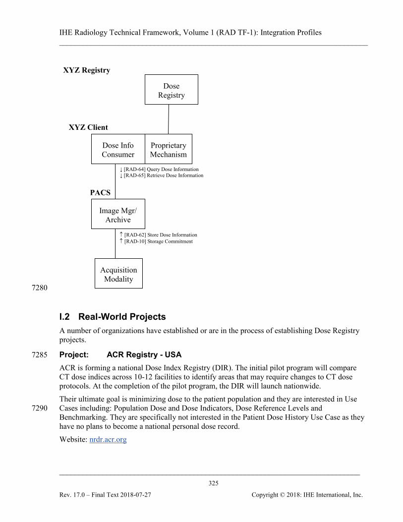
IHE Radiology Technical Framework, Volume 1 (RAD TF-1): Integration Profiles ______________________________________________________________________________
____________________________________________________________________________ 325
Rev. 17.0 – Final Text 2018-07-27 Copyright © 2018: IHE International, Inc.
7280
I.2 Real-World Projects A number of organizations have established or are in the process of establishing Dose Registry projects.
Project: ACR Registry - USA 7285 ACR is forming a national Dose Index Registry (DIR). The initial pilot program will compare CT dose indices across 10-12 facilities to identify areas that may require changes to CT dose protocols. At the completion of the pilot program, the DIR will launch nationwide. Their ultimate goal is minimizing dose to the patient population and they are interested in Use Cases including: Population Dose and Dose Indicators, Dose Reference Levels and 7290 Benchmarking. They are specifically not interested in the Patient Dose History Use Case as they have no plans to become a national personal dose record. Website: nrdr.acr.org
↑ [RAD-62] Store Dose Information ↑ [RAD-10] Storage Commitment
PACS
XYZ Client
↓ [RAD-64] Query Dose Information ↓ [RAD-65] Retrieve Dose Information
Dose Registry
Dose Info Consumer
Acquisition Modality
Image Mgr/ Archive
Proprietary Mechanism
XYZ Registry
IHE Radiology Technical Framework, Volume 1 (RAD TF-1): Integration Profiles ______________________________________________________________________________
____________________________________________________________________________ 326
Rev. 17.0 – Final Text 2018-07-27 Copyright © 2018: IHE International, Inc.
Project: French Ministry of Health Registry French regulations mandate the submission of Dose Reference Level data to a federal dose 7295 registry managed by the Institut de Radioprotection et de Sûreté Nucléaire / Institute for Radiation Protection and Nuclear Safety (IRSN). Every year each specialist must submit dosimetric information (at least 20 patients) for each of at least two examination types (generally the most frequent and most irradiating examination types). 7300 The ministry is interested in Use Cases including: Population Dose and Dose Indicators, and Dose Reference Levels. Data collection spans Radiography, Fluoroscopy, Mammography, Computed Tomography and Nuclear Medicine. The data is further broken down by patient age category, and body part. Website: www.irsn.org/en 7305
I.3 Dose Monitoring Regulations Several groups interested in regulatory issues (IEC, FDA, AAPM, etc.) drove original definition of the DICOM Dose SR objects. The following sections contain some contributed summaries of different regulatory initiatives. These are only intended to provide a sense of the type of activities. Readers should refer to the 7310 regulations themselves for accurate information.
European Regulatory European regulation is based on European Directive Euratom 1997/43/EC. The application of the directive is mandatory in all EU countries (27 today) since 2000. All European national regulations have to be compatible with the directive. Different countries have varied in their 7315 reactions/actions to Euratom. Euratom specifies a follow up for each patient and statistical analysis at the population level. Euratom: http://ec.europa.eu/energy/nuclear/radioprotection/legislation_en.htm Diagnostic Reference Levels (DRLs) in Europe: http://www.eu-alara.net/index.php?option=com_content&task=view&id=156&Itemid=53 7320
French Regulatory Today two regulations specify the dosimetric information that a user of ionising radiation must provide in France.
• One text, published in March 2004, concerns Dose Reference Levels (DRL) (Arrêté du 12 février 2004 relatif aux niveaux de référence diagnostiques en radiologie et en 7325 médecine nucléaire – Journal Officiel de la République Française du 16 mars 2004).
• Another text, published in September 2006, concerns dosimetric information that must be present in the medical record of the diagnostic examination (Arrêté du 22 septembre 2006

IHE Radiology Technical Framework, Volume 1 (RAD TF-1): Integration Profiles ______________________________________________________________________________
____________________________________________________________________________ 327
Rev. 17.0 – Final Text 2018-07-27 Copyright © 2018: IHE International, Inc.
relatif aux informations dosimétriques devant figurer dans un compte rendu d'acte utilisant les rayonnements ionisants - Journal Officiel de la République Française du 29 7330 septembre 2006).
For each medical procedure using ionising radiation, the medical record must include information allowing estimation of the dose received by the patient.
German & Dutch Regulatory In Germany and the Netherlands, dose information is not conveyed above the Hospital level. 7335 Dose information is required and must be auditable. Germany is working on additions to the DICOM Basic Diagnostic Imaging Report to include Radiation Regulation related details such as:
• Pregnancy Status
• Indications for Procedure 7340
• Physician Responsible for Indication
• Performing Person (who administered)
• Radioactive Substance Administered
• Radiation Exposure (text description of "the exposure")
• Performing Person’s Organization Name 7345
Spanish Regulatory In Spain, dose information is not conveyed above the Hospital level. Dose information is required in order to audit the use of diagnostic equipment (comparing with Dose Reference Levels) and must be auditable by the responsible health authority. Also the responsible health authority and the Nuclear Security Council will guarantee that the distribution 7350 of the estimations of resulting individual doses is determined, for the population and the significant groups of reference of the population, whose results will be sent to the Ministry of Health and Consumption.
IHE Radiology Technical Framework, Volume 1 (RAD TF-1): Integration Profiles ______________________________________________________________________________
____________________________________________________________________________ 328
Rev. 17.0 – Final Text 2018-07-27 Copyright © 2018: IHE International, Inc.
GLOSSARY 7355
Terms Specific to this Document Accession Number: A user-friendly identifier created by the Departmental System, which identifies an instance of a filler order or imaging service request. It may group one or more requested procedures. Actor: An entity within a use case diagram that can perform an action within a use case diagram. 7360 Possible actions are creation or consumption of a message. Conventional 2D mammography: Refers to mammography images that have been acquired using FFDM. Dose Object: A persistent DICOM object (See DICOM PS 3.3: A.35.8 X-Ray Radiation Dose SR IOD) for recording details related to Irradiation Events. DICOM has defined Dose Objects 7365 for CT and Projection X-ray procedures. Dose Registry: A system that collects dose information from multiple sites, generally to perform analysis of Population Dose and Dose Indicators. DVD: A trademark of the DVD Forum that is not an abbreviation Evidence Documents: Evidence Documents represent the uninterpreted information that is 7370 primarily managed and used inside the imaging department, although distribution outside the imaging department is not precluded. Evidence documents are non-image information and include things such as measurements, CAD results, procedure logs, etc. and are to be encoded as DICOM SR documents. Evidence Objects: All objects generated as a result of performing procedure steps on systems in 7375 an imaging department. These objects are used by the reading physician in the process of creating a diagnostic report and are managed inside the imaging Department. Examples of evidence objects include: Images, Presentation States, Key Image Notes and Evidence Documents. Expected Actions: Actions which should occur as the result of a trigger event 7380 Foreign Key (FK): A database key that is used as a reference to relate one entity to another entity. It may be a unique value, or used in conjunction with another Foreign Key to create a unique value. Hardcopy Import: The process of importing non-digital data into the Enterprise as DICOM Objects. The original data may be Films or Documents that are scanned and stored as DICOM 7385 Objects. Images Available: A transaction or transactions used to determine that images have been stored in an image archive and may be retrieved. Interaction Diagram: A diagram which depicts data flow and sequencing of events Interchange Media: A piece of data-bearing physical media, such as a CD or DVD. The term, 7390 which is used in the DICOM standard, is synonymous with “portable media” or “transfer media”.
IHE Radiology Technical Framework, Volume 1 (RAD TF-1): Integration Profiles ______________________________________________________________________________
____________________________________________________________________________ 329
Rev. 17.0 – Final Text 2018-07-27 Copyright © 2018: IHE International, Inc.
Irradiation Event: An irradiation event is one continuous occurrence of irradiation being applied to a patient. A pulsed fluoro X-Ray acquisition, or a multi-slice helical CT scan are examples of single events; while a CT scanogram and the helical scan, or two different presses of the fluoro pedal, or simultaneous irradiation from two X-ray tubes are examples of separate 7395 events. See RAD TF-3: 4.62.4.1.1 in Store Dose Information for a more detailed description Pre-fetch: The activity of fetching images or other information objects from previously completed procedures to near-term storage for review of those data. Process Flow Diagram: A graphical illustration of the flow of processes and interactions among the actors involved in a particular example 7400 Role: The actions of an actor in a use case. Scope: A brief description of the transaction. Slab: A thick slice tomosynthesis reconstruction (e.g., greater than 1mm). Trigger Event: An event such as the reception of a message or completion of a process, which causes another action to occur. 7405 Use Case: A graphical depiction of the actors and operation of a system. W3C: A trademark of the World Wide Web Consortium that is not an abbreviation Web-Viewable: Browsable using a web browser (e.g., XHTML files and JPEG images) XDS Imaging Document: An XDS Imaging Document is the smallest unit of imaging related information that may be provided to a Document Repository and registered in a Document 7410 Registry. An XDS Imaging Document may contain a manifest of images (e.g., DICOM Key Object Selection document) or a radiology report provided either as a PDF document or as structured and vocabulary coded clinical information (e.g., CDA Release 2).
DICOM Terms 7415 Basic Color Print Management Meta SOP Class: See DICOM PS3.4 Basic Grayscale Print Management Meta SOP Class: See DICOM PS3.4 Basic Text SR Storage SOP Class: See DICOM Supplement 23 DICOM Model of the Real World: See DICOM PS3.3 Enhanced SR Storage SOP Class: See DICOM Supplement 23 7420 Grayscale Softcopy Presentation State Storage SOP Class: See DICOM PS3.4 Grayscale Standard Display Function: DICOM PS3.14 Imaging Service Request: See DICOM PS .3 Modality: See DICOM PS3.3 Modality Worklist SOP Class: See DICOM PS3.4 7425
IHE Radiology Technical Framework, Volume 1 (RAD TF-1): Integration Profiles ______________________________________________________________________________
____________________________________________________________________________ 330
Rev. 17.0 – Final Text 2018-07-27 Copyright © 2018: IHE International, Inc.
Modality Performed Procedure Step: See DICOM PS3.3 Modality Performed Procedure Step Information Module: See DICOM PS3.3 Modality Performed Procedure Step Relationship Module: See DICOM PS3.3 Modality Performed Procedure Step SOP Class: See DICOM PS3.4 Patient: See DICOM PS3.3 7430 Patient Identification Module: See DICOM PS3.3 Print Presentation LUT SOP Class: See DICOM PS3.4 Procedure Plan: See DICOM PS3.3 Procedure Type: See DICOM PS3.3 Protocol Code: See DICOM PS3.3 7435 Requested Procedure: See DICOM PS3.3 Requested Procedure Module: See DICOM PS3.3 Requested Procedure ID: See DICOM PS3.3 Results Information Object Definition: See DICOM PS3.3 Scheduled Procedure Step: See DICOM PS3.3 7440 Scheduled Procedure Step Module: See DICOM PS3.3 Storage Commitment SOP Class: See DICOM PS3.4 Stored Print SOP Class: See DICOM PS3.4 Structured Reporting Information Object Definitions: See DICOM PS3.3 Structured Reporting SOP Classes: See DICOM PS3.4 7445 Structured Reporting Templates: See DICOM PS3.16 Unique Identifier (UID): See DICOM PS3.5
HL7 Terms ADT: See HL7 version 2.3.1 7450 Battery: See HL7 version 2.3.1 Filler: See HL7 version 2.3.1 Observation: See HL7 version 2.3.1 Placer: See HL7 version 2.3.1 Universal Service ID: See HL7 version 2.3.1 7455

IHE Radiology Technical Framework, Volume 1 (RAD TF-1): Integration Profiles ______________________________________________________________________________
____________________________________________________________________________ 331
Rev. 17.0 – Final Text 2018-07-27 Copyright © 2018: IHE International, Inc.
Acronyms and Abbreviations ACR: American College of Radiology CAD: Computer Aided Detection CD: Compact Disk 7460 DAP: Dose Area Product DBT: Digital Breast Tomosynthesis DLP: Dose Length Product FDA: Food and Drug Administration (USA) FFDM: Full Field Digital Mammography 7465 FSC: File-Set Creator FSR: File-Set Reader GSPS: Grayscale Softcopy Presentation State HIMSS: Healthcare Information and Management Systems Society HIS: Hospital Information System 7470 HTML: Hyper Text Markup Language ICRU: International Commission on Radiological Units IEC: International Electrotechnical Commission IHE: Integrating the Healthcare Enterprise IOD: Information Object Definitions 7475 IT: Information Technology JPEG: Joint Photographic Experts Group LUT: Look Up Table MPI: Master Patient Index MPPS: Modality Performed Procedure Step 7480 MQSA: Mammography Quality Standards Act of 1992 MWL: Modality Worklist NEMA: National Electrical Manufacturers Association PACS: Picture Archive and Communication System PHI: Protected Healthcare Information 7485 PPS: Performed Procedure Step PSD: Peak Skin Dose
IHE Radiology Technical Framework, Volume 1 (RAD TF-1): Integration Profiles ______________________________________________________________________________
____________________________________________________________________________ 332
Rev. 17.0 – Final Text 2018-07-27 Copyright © 2018: IHE International, Inc.
QA: Quality Assurance RIS: Radiology Information System RSNA: Radiological Society of North America 7490 SCU: Service Class User SCP: Service Class Provider SR: Structured Report UID: Unique Identifier USB: Universal Serial Bus 7495 XHTML: eXtensible Hypertext Markup Language
References [1] American College of Radiology White Paper on Radiation Dose in Medicine, E. Stephen Amis, et al, Journal of American College of Radiology, 2007, Vol. 4, pp. 272-284 [2] Quality Improvement Guidelines for Recording Patient Radiation Dose in the Medical 7500 Record, Donald Miller, Stephen Balter, et al, Journal of Vascular Interventional Radiology, 2004, Vol. 15, pp. 423-429 [3] ICRU. Report 74: Patient Dosimetry for X-Rays Used in Medical Imaging. JICRU 5; 2005. [4] IEC. IEC 60601. (2000). Medical electrical equipment - Part 2-43: Particular 7505 requirements for the safety of X-ray equipment for interventional procedures. Geneva; 2000. [5] IEC. PAS 61910-1 Radiation Dose Documentation Part 1: Equipment for radiography and radioscopy. Geneva; 2007. [6] FDA. Federal performance standard for diagnostic x-ray systems and their major components-- FDA. Final rule. Fed Regist 70: 33998 - 34042; 2005. 7510 [7] Capturing Patient Doses from Fluoroscopically Based Diagnostic and Interventional Systems, Stephen Balter, NCRP Annual Meeting-07; 2008